
Evaluation of Grip Force and Energy Efficiency of the “Federica” Hand

 ,
,  ,
,  ,
,  , ,
, ,  ,
, 
Abstract
1. Introduction
2. Materials and Methods
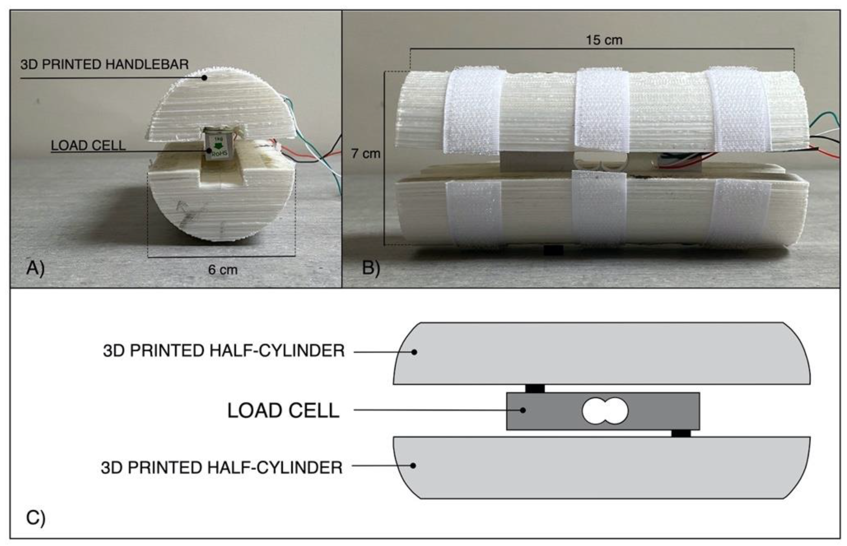
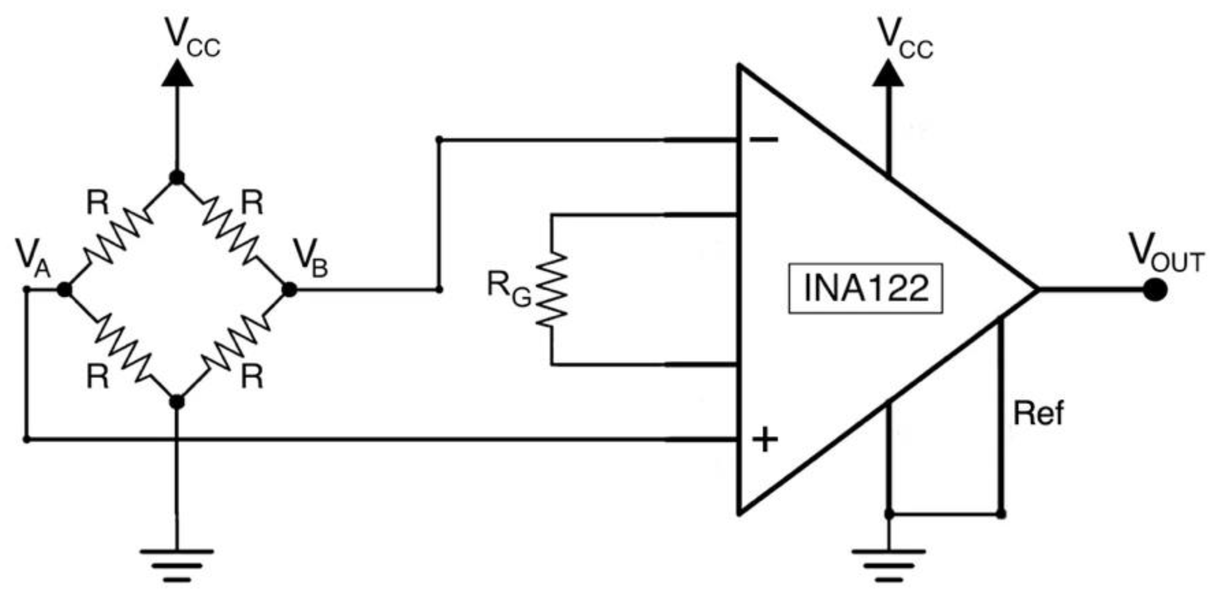
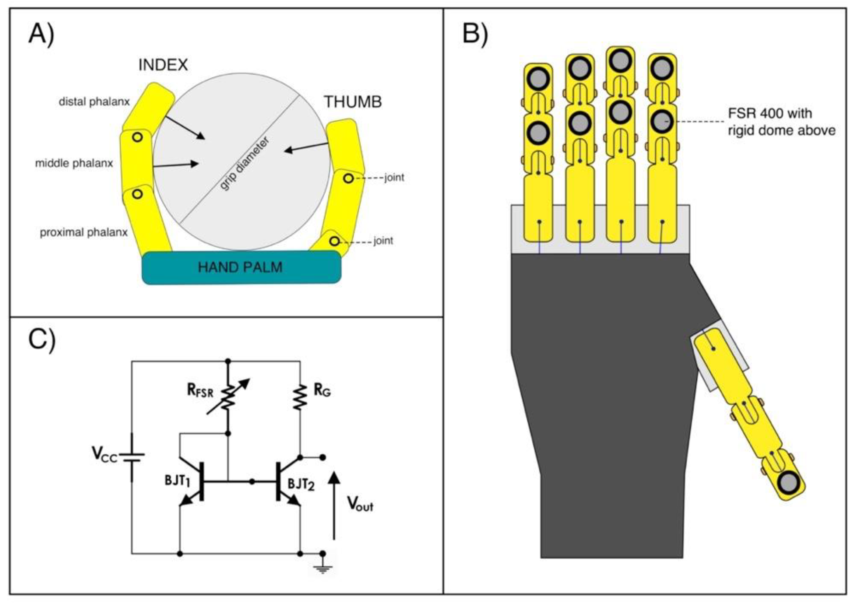
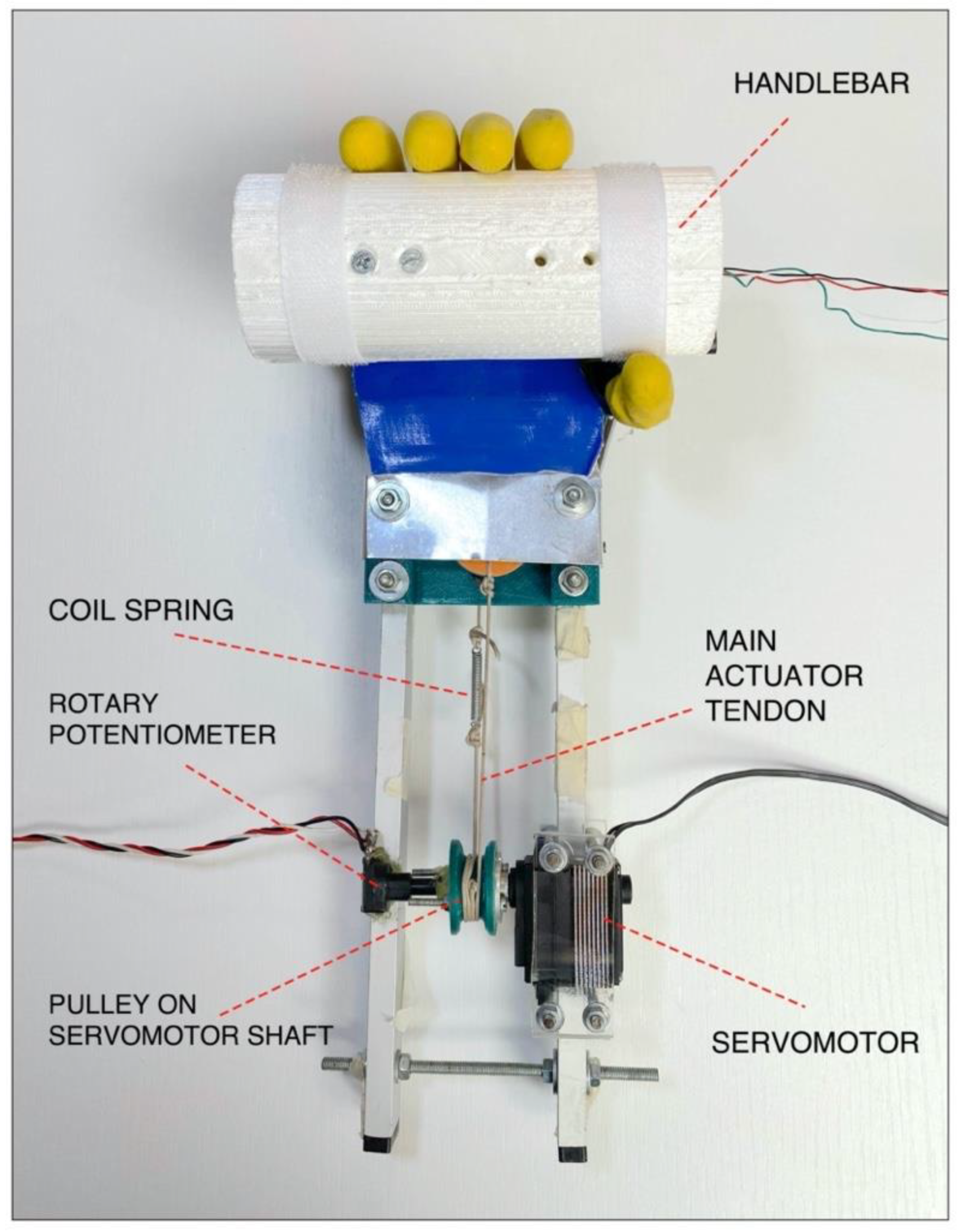
2.1. Grip Force Measurement System
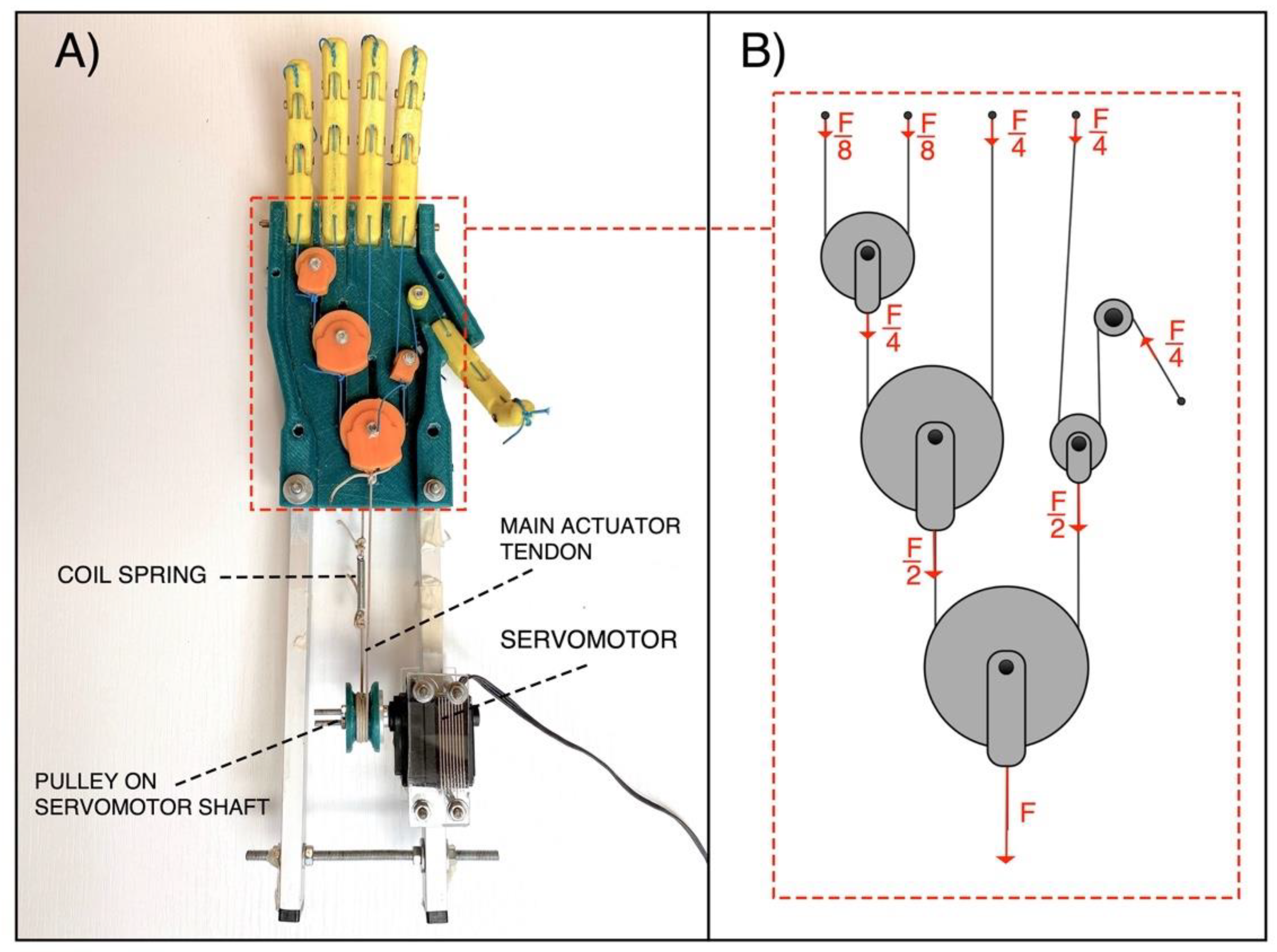
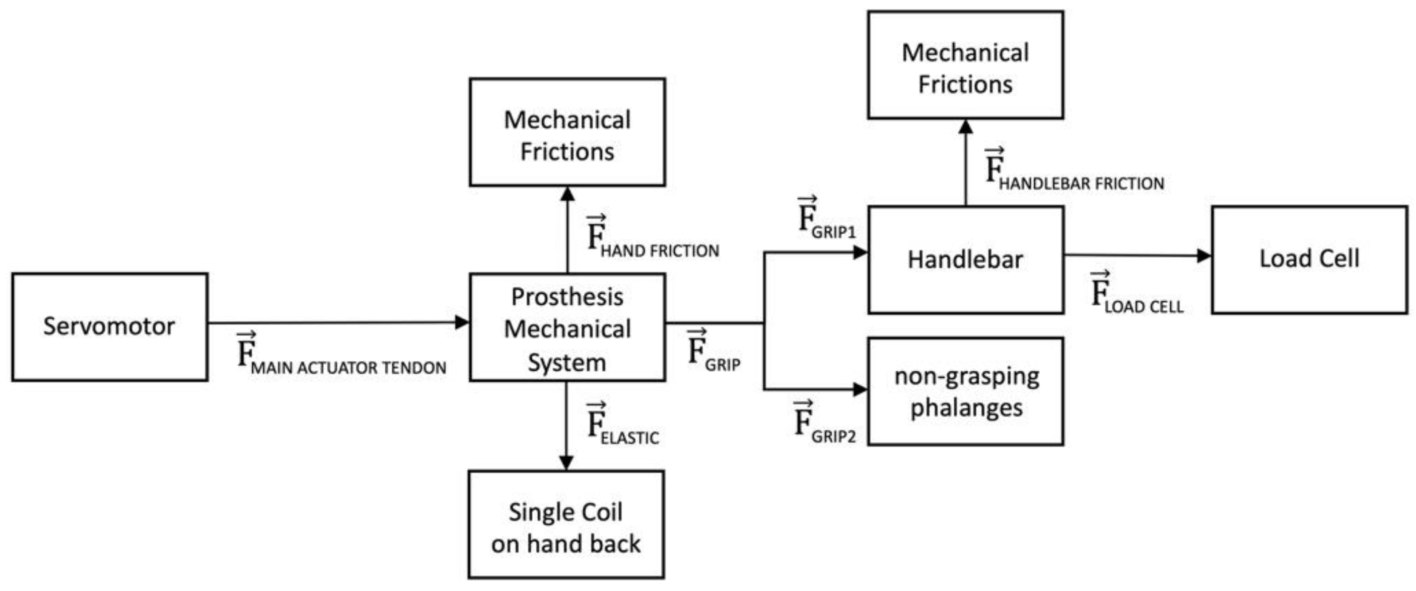
2.2. Prosthetic Mechanical System and Its Force Transfer Ratio
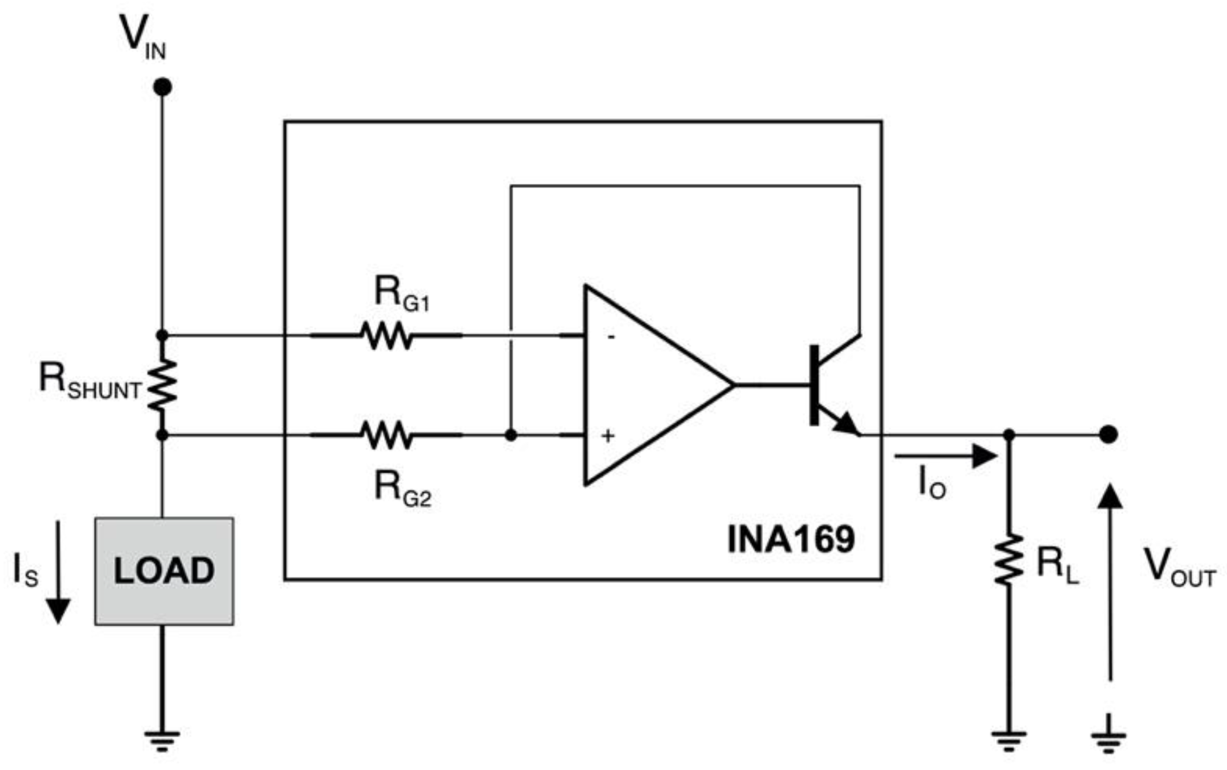
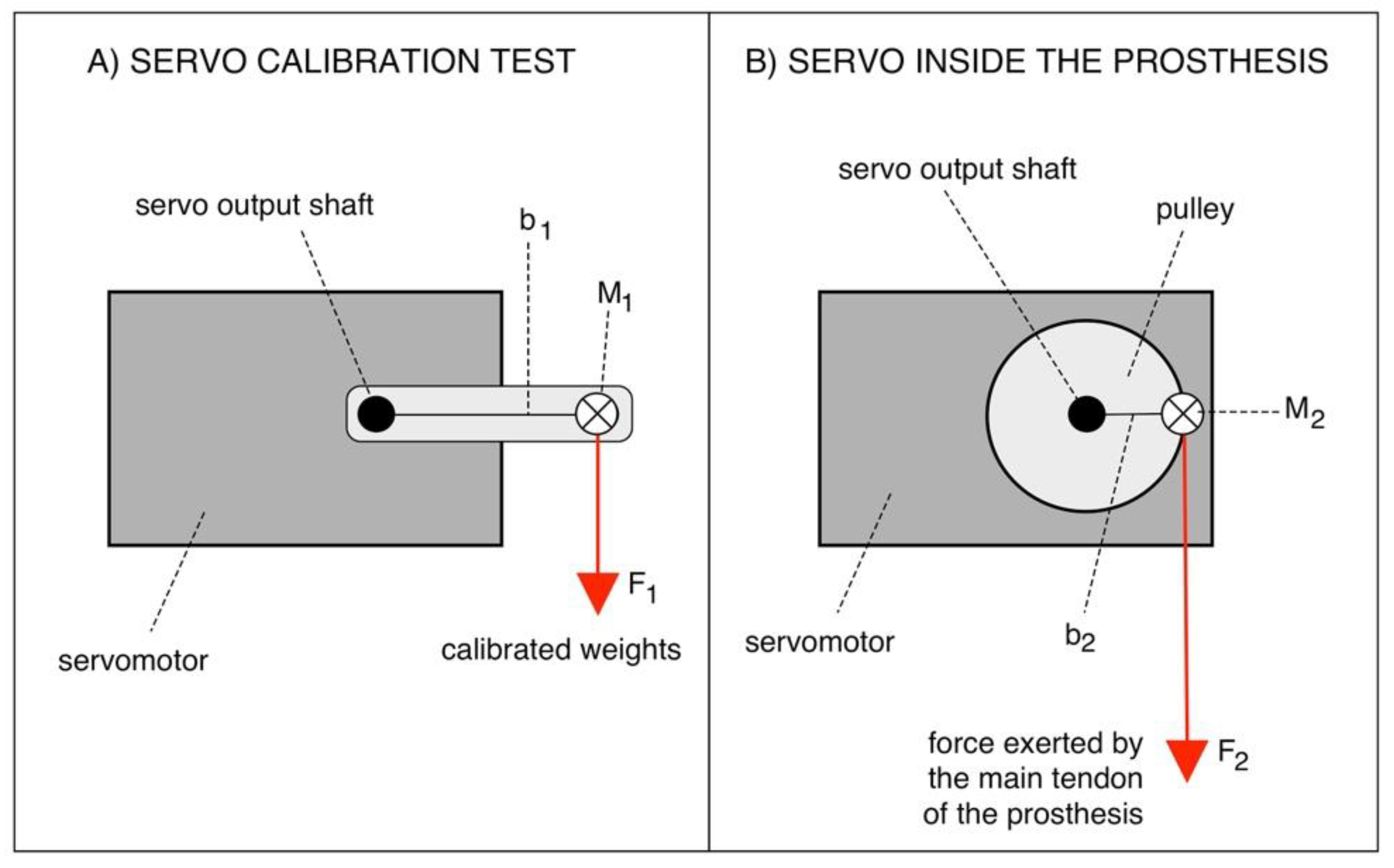
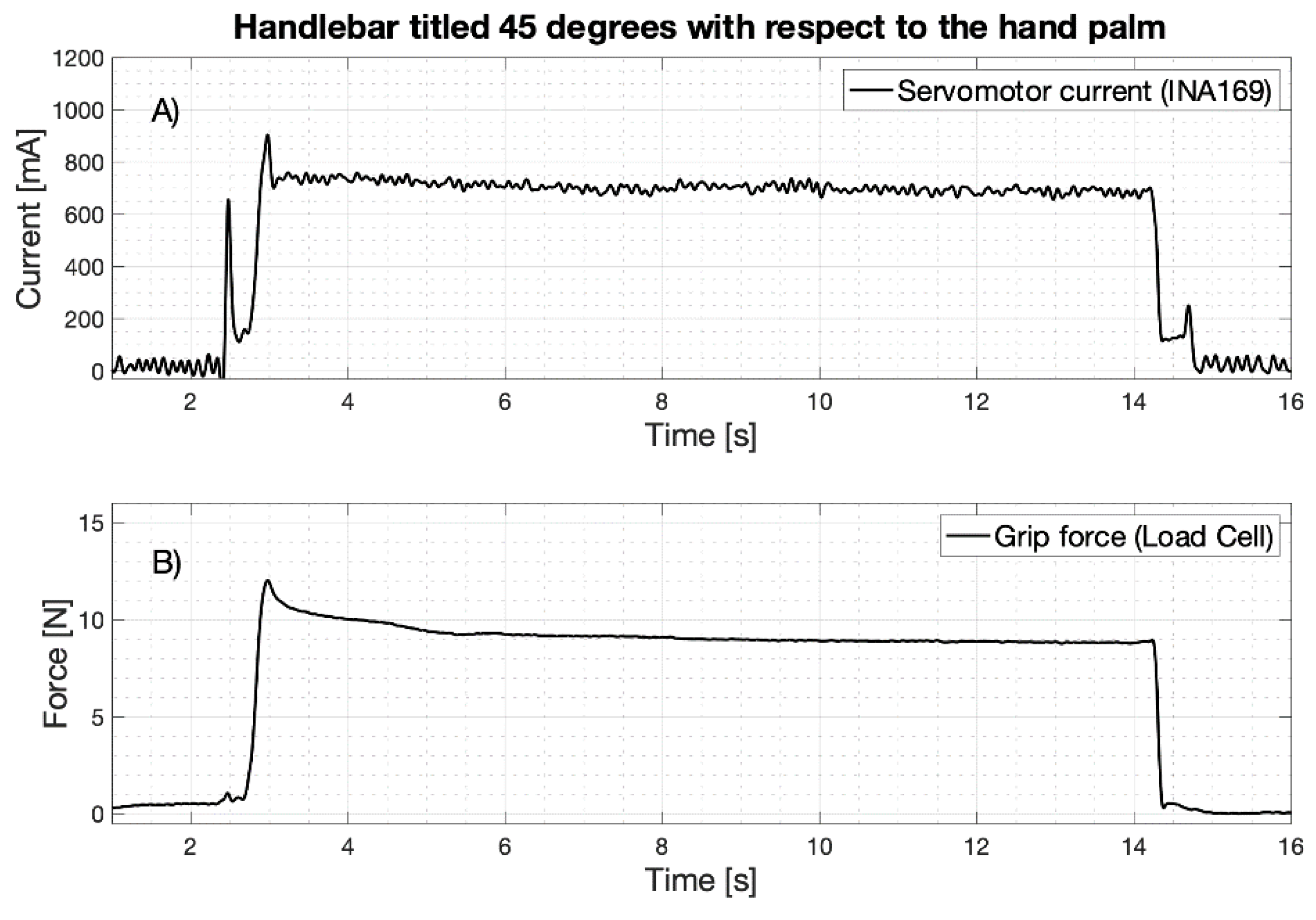
2.3. Estimation of Main Tendon Force from Servomotor Current Absorption
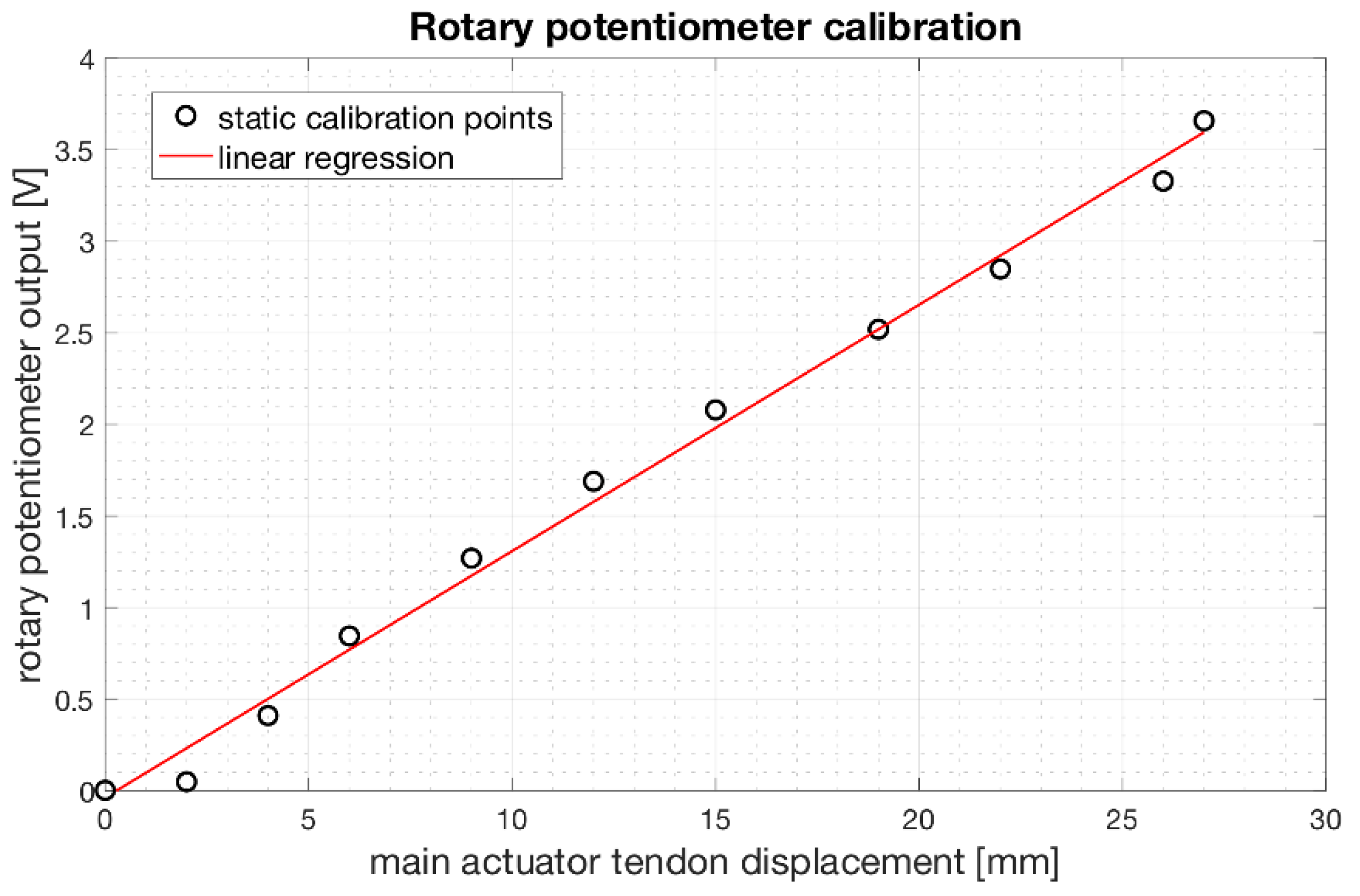
2.4. Estimation of Main Tendon Displacement
2.5. Estimation of Work
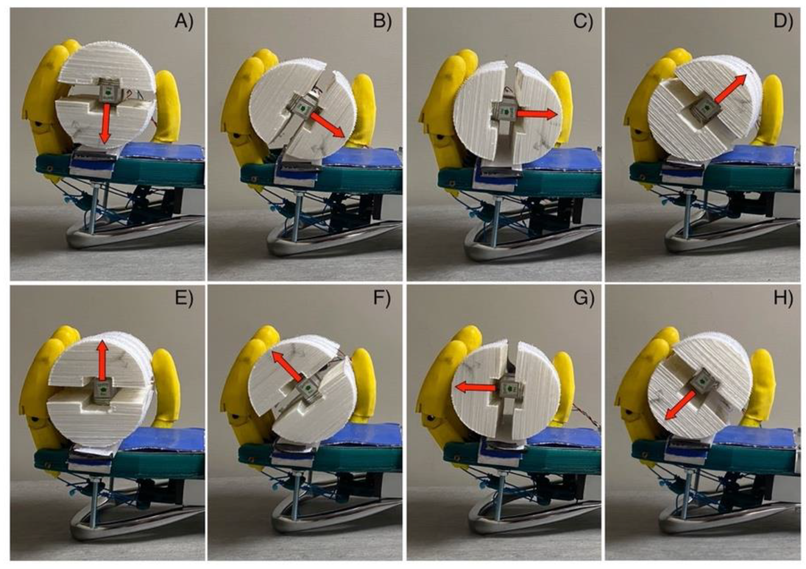
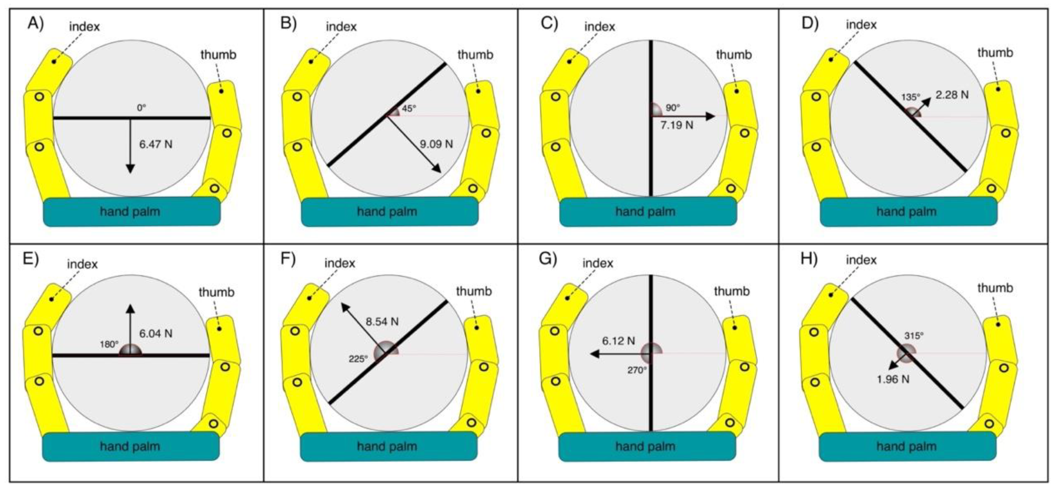
2.6. Experimental Grip Tests with the Load Cell in Different Positions
3. Results
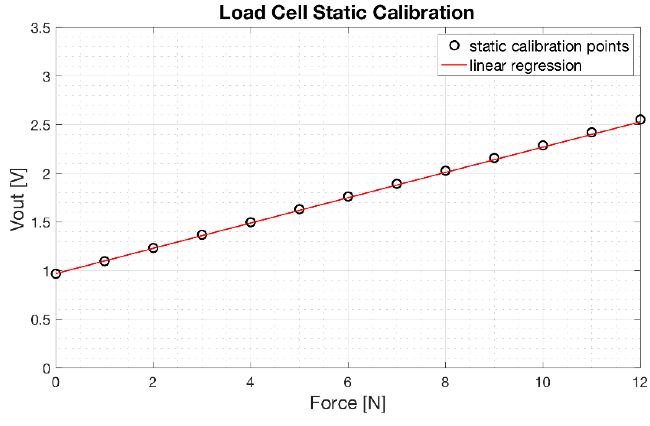
3.1. Load Cell Static Calibration
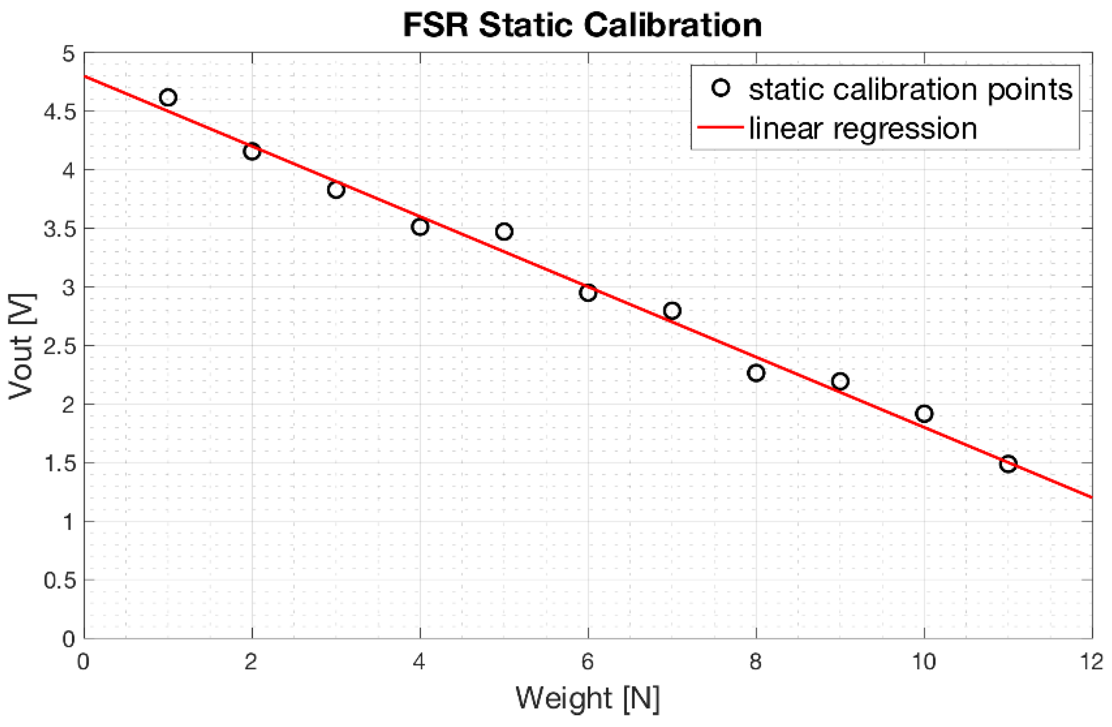
3.2. FSRs Static Calibrations
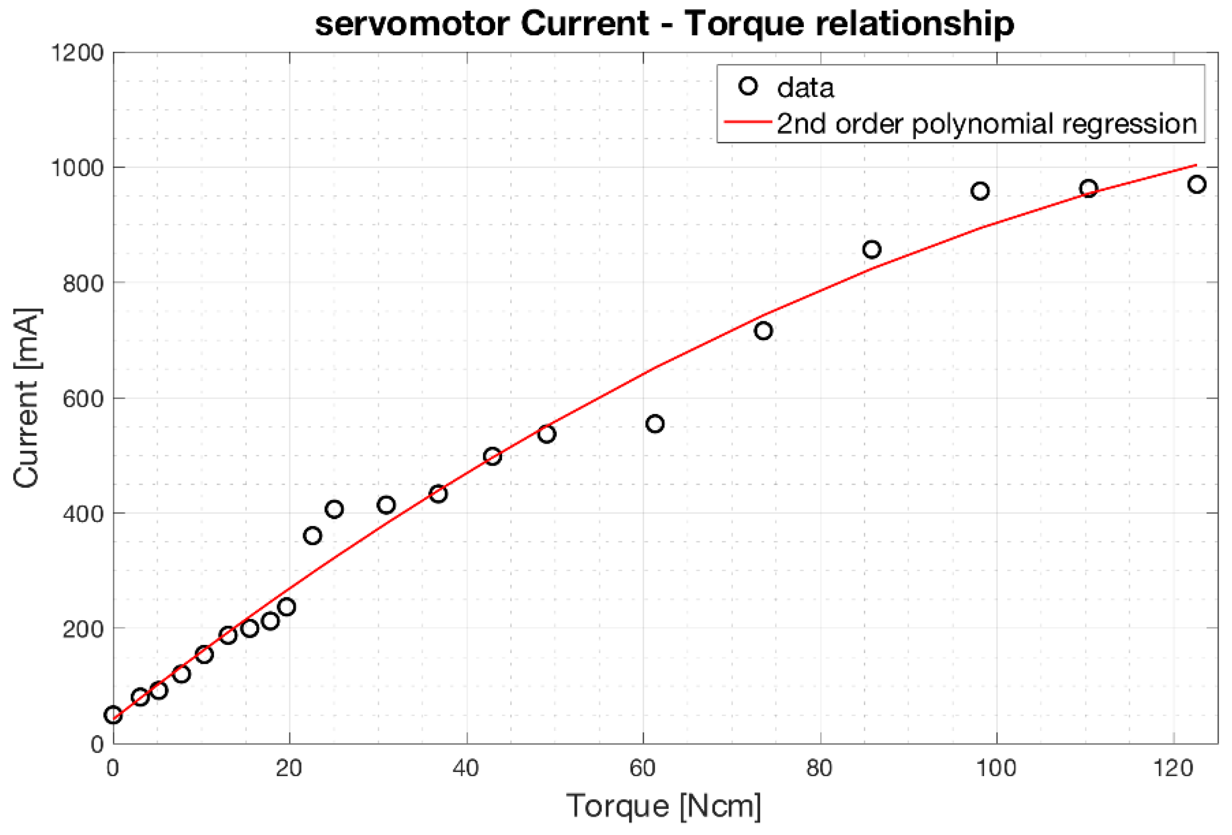
3.3. Servomotor Characterization
3.4. Rotary Potentiometer Calibration
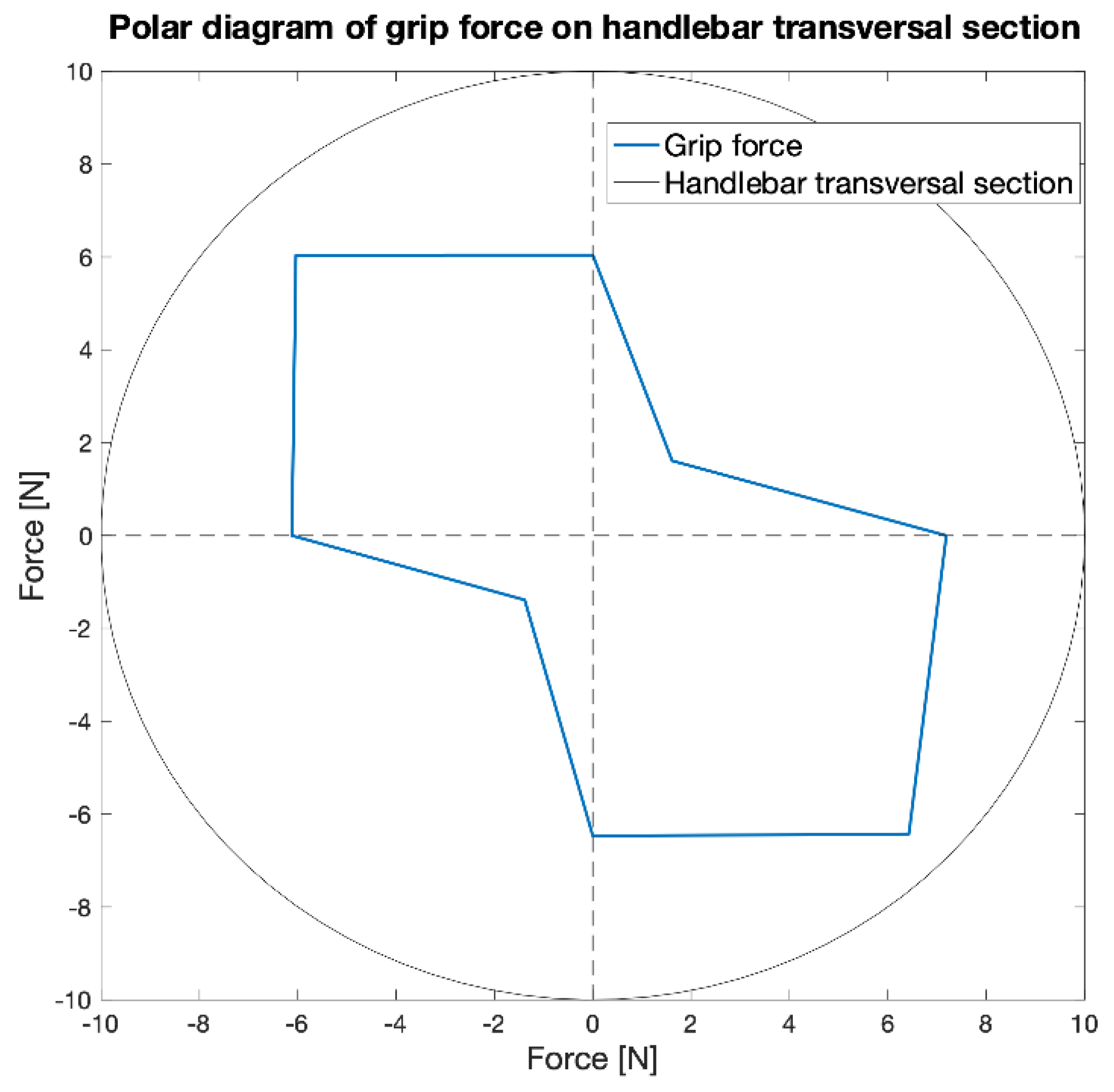
3.5. Results of the Experimental Grip Tests
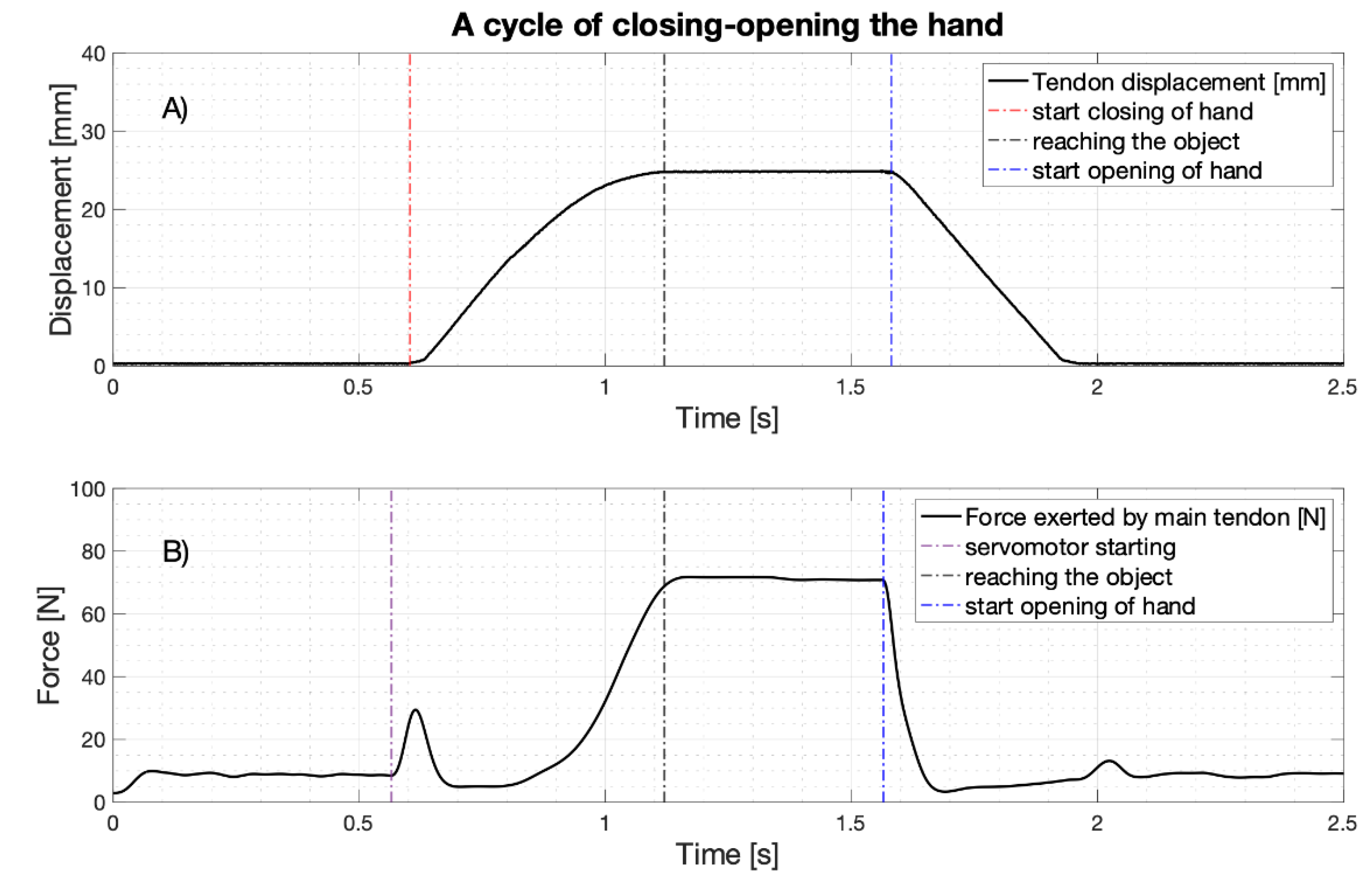
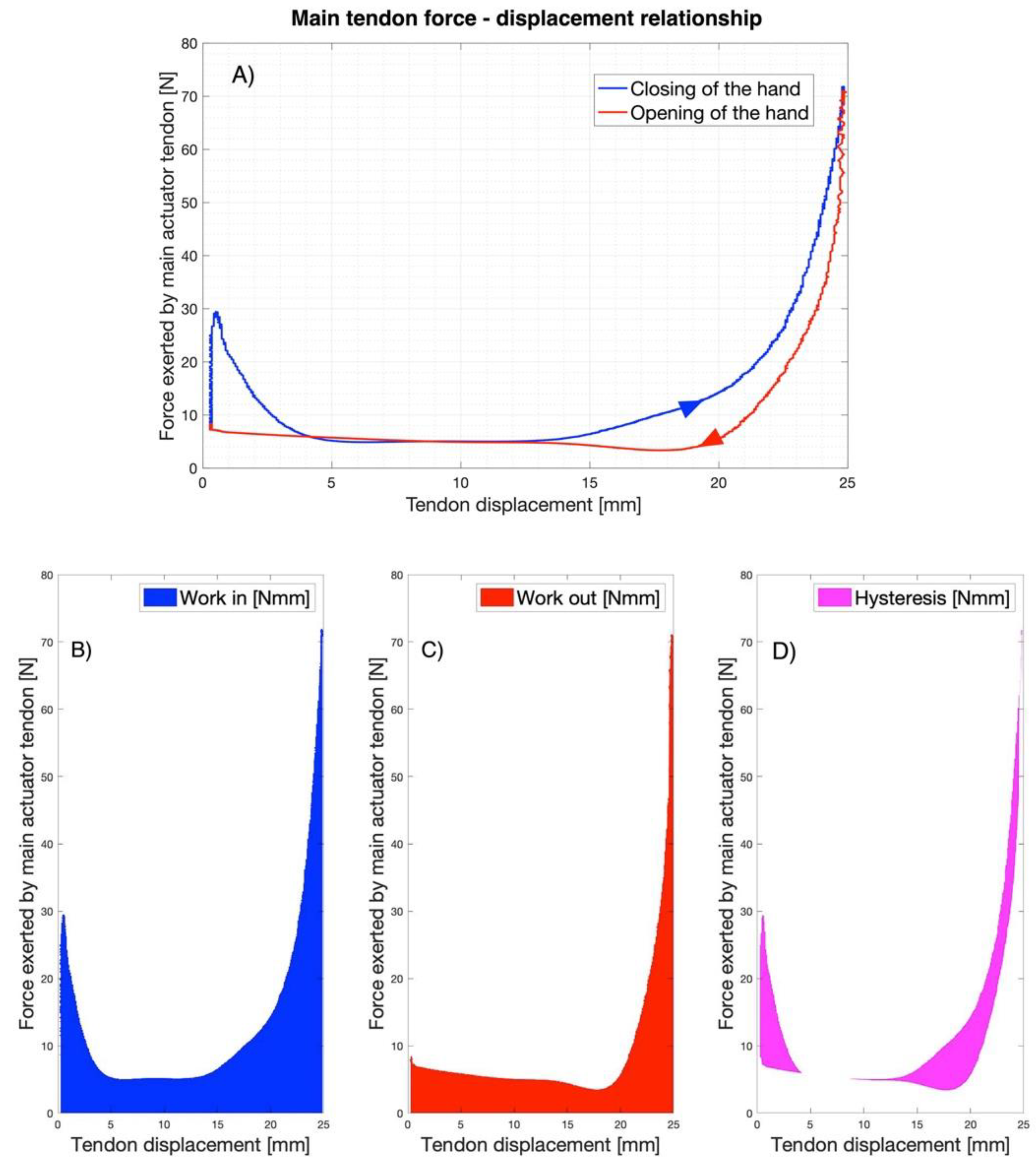
3.6. Work for Closing-Opening the Hand and Hysteresis Cycle
4. Discussion
4.1. Limits of the Study
4.2. Future Perspectives
Author Contributions
Funding
Institutional Review Board Statement
Informed Consent Statement
Data Availability Statement
Conflicts of Interest
References
- Kurillo, G.; Gregorič, M.; Goljar, N.; Bajd, T. Grip force tracking system for assessment and rehabilitation of hand function. Technol. Health Care Off. J. Eur. Soc. Eng. Med. 2005, 13, 137–149. [Google Scholar] [CrossRef]
- Belter, J.T.; Dollar, A.M. Performance characteristics of anthropomorphic prosthetic hands. In Proceedings of the 2011 IEEE International Conference on Rehabilitation Robotics, Zurich, Switzerland, 29 June–1 July 2011; pp. 1–7. [Google Scholar]
- Belter, J.T.; Leddy, M.T.; Gemmell, K.D.; Dollar, A.M. Comparative clinical evaluation of the yale multigrasp hand. In Proceedings of the 2016 6th IEEE International Conference on Biomedical Robotics and Biomechatronics (BioRob), Singapore, 26–29 June 2016; pp. 528–535. [Google Scholar]
- Weiner, P.; Starke, J.; Hundhausen, F.; Beil, J.; Asfour, T. The KIT prosthetic hand: Design and control. In Proceedings of the 2018 IEEE/RSJ International Conference on Intelligent Robots and Systems (IROS), Madrid, Spain, 1–5 October 2018. [Google Scholar] [CrossRef]
- Fu, Q.; Santello, M. Improving fine control of grasping force during hand–object interactions for a soft synergy-inspired myoelectric prosthetic hand. Front. Neurorobot. 2018, 11, 71. [Google Scholar] [CrossRef]
- Irwin, C.B.; Towles, J.D.; Radwin, R.G. Development and application of a multi-axis dynamometer for measuring grip force. Ergonomics 2013, 56, 1841–1849. [Google Scholar] [CrossRef] [PubMed]
- Szewczyk, R.; Zieliński, C.; Kaliczyńska, M. Automation 2019: Progress in Automation, Robotics and Measurement Techniques; Springer: Berlin/Heidelberg, Germany, 2019; ISBN 978-3-030-13273-6. [Google Scholar]
- Measure Grip Forces. Available online: https://www.tekscan.com/measure-grip-forces (accessed on 18 August 2020).
- Interlink Electronics Inc. FSR Sensor, Force Sensing Resistor. Available online: https://www.interlinkelectronics.com/force-sensing-resistor (accessed on 13 November 2020).
- Carbone, G.; Rossi, C.; Savino, S. Performance comparison between FEDERICA hand and larm hand. Int. J. Adv. Robot. Syst. 2015, 12, 90. [Google Scholar] [CrossRef]
- Pylatiuk, C.; Kargov, A.; Schulz, S.; Döderlein, L. Distribution of grip force in three different functional prehension patterns. J. Med. Eng. Technol. 2006, 30, 176–182. [Google Scholar] [CrossRef] [PubMed]
- Kargov, A.; Pylatiuk, C.; Martin, J.; Schulz, S.; Döderlein, L. A comparison of the grip force distribution in natural hands and in prosthetic hands. Disabil. Rehabil. 2004, 26, 705–711. [Google Scholar] [CrossRef] [PubMed]
- Cosenza, C.; Niola, V.; Savino, S. A mechanical hand for prosthetic applications: Multibody model and contact simulation. Proc. Inst. Mech. Eng. 2018, 232, 819–825. [Google Scholar] [CrossRef] [PubMed]
- Carrozza, M.C.; Suppo, C.; Sebastiani, F.; Massa, B.; Vecchi, F.; Lazzarini, R.; Cutkosky, M.R.; Dario, P. The SPRING hand: Development of a self-adaptive prosthesis for restoring natural grasping. Auton. Robot. 2004, 16, 125–141. [Google Scholar] [CrossRef]
- Kamikawa, Y.; Maeno, T. Underactuated five-finger prosthetic hand inspired by grasping force distribution of humans. In Proceedings of the 2008 IEEE/RSJ International Conference on Intelligent Robots and Systems, IROS, Nice, France, 22–26 September 2008; pp. 717–722. [Google Scholar]
- Bifulco, P.; Esposito, D.; Gargiulo, G.D.; Savino, S.; Niola, V.; Iuppariello, L.; Cesarelli, M. A stretchable, conductive rubber sensor to detect muscle contraction for prosthetic hand control. In Proceedings of the 2017 E-Health and Bioengineering Conference (EHB), Sinaia, Romania, 22–24 June 2017; pp. 173–176. [Google Scholar]
- Esposito, D.; Cosenza, C.; Gargiulo, G.D.; Andreozzi, E.; Niola, V.; Fratini, A.; D’Addio, G.; Bifulco, P. Experimental study to improve “Federica” prosthetic hand and its control system. In Proceedings of the XV Mediterranean Conference on Medical and Biological Engineering and Computing—MEDICON 2019, Coimbra, Portugal, 26–28 September 2019; Henriques, J., Neves, N., de Carvalho, P., Eds.; Springer International Publishing: Coimbra, Portugal, 2020; pp. 586–593. [Google Scholar]
- Esposito, D.; Savino, S.; Cosenza, C.; Gargiulo, G.D.; Fratini, A.; Cesarelli, G.; Bifulco, P. Study on the activation speed and the energy consumption of “Federica” prosthetic hand. In Proceedings of the XV Mediterranean Conference on Medical and Biological Engineering and Computing—MEDICON 2019, Coimbra, Portugal, 26–28 September 2019; Henriques, J., Neves, N., de Carvalho, P., Eds.; Springer International Publishing: Coimbra, Portugal, 2020; pp. 594–603. [Google Scholar]
- Federica Prosthetic Hand. Available online: http://ingegneria-biomedica.dieti.unina.it/index.php/en/projects/federica-prosthetic-hand.html (accessed on 18 August 2020).
- Esposito, D.; Andreozzi, E.; Fratini, A.; Gargiulo, G.D.; Savino, S.; Niola, V.; Bifulco, P. A piezoresistive sensor to measure muscle contraction and mechanomyography. Sensors 2018, 18, 2553. [Google Scholar] [CrossRef] [PubMed]
- Esposito, D.; Andreozzi, E.; Gargiulo, G.D.; Fratini, A.; D’Addio, G.; Naik, G.R.; Bifulco, P. A piezoresistive array armband with reduced number of sensors for hand gesture recognition. Front. Neurorobot. 2020, 13, 114. [Google Scholar] [CrossRef] [PubMed]
- Falco, J.; Van Wyk, K.; Messina, E. Performance Metrics and Test Methods for Robotic Hands. NIST Tech. Rep. DRAFT NIST 2018, 1227. [Google Scholar] [CrossRef]
- INA122 Data Sheet, Product Information and Support|TI.Com. Available online: https://www.ti.com/product/INA122 (accessed on 20 August 2020).
- Hitec HITEC Robot Servo. Available online: https://hitecrcd.com/products/servos/discontinued-servos-servo-accessories/hsr-5990tg-hmi-ultra-premium-robot-servo/product (accessed on 20 August 2020).
- Industries, A. INA169 Analog DC Current Sensor Breakout—60V 5A Max. Available online: https://www.adafruit.com/product/1164 (accessed on 20 August 2020).
- Smit, G.; Bongers, R.M.; Van der Sluis, C.K.; Plettenburg, D.H. Efficiency of voluntary opening hand and hook prosthetic devices: 24 years of development? J. Rehabil. Res. Dev. 2012, 49, 523–534. [Google Scholar] [CrossRef] [PubMed]
- Smit, G.; Plettenburg, D.H. Efficiency of voluntary closing hand and hook prostheses. Prosthet. Orthot. Int. 2010, 34, 411–427. [Google Scholar] [CrossRef] [PubMed]
- De Visser, H.; Herder, J.L. Force-Directed design of a voluntary closing hand prosthesis. J. Rehabil. Res. Dev. 2000, 37, 261–271. [Google Scholar] [PubMed]
- Hagler, S. Patterns of Selection of Human Movements IV: Energy Efficiency, Mechanical Advantage, and Asynchronous Arm-Cranking. arXiv 2018, arXiv:1702.03271. [Google Scholar]


| Load Cell Tilt [Degrees] | Mean Force Exerted on the Load Cell [N] | Mean Current Absorbed by the Servomotor [mA] | Estimated Tensile Force Exerted on the Main Tendon of the Prosthesis [N] |
|---|---|---|---|
| 0 | 6.47 | 758 | 75.64 |
| 45 | 9.09 | 702 | 67.81 |
| 90 | 7.19 | 685 | 65.50 |
| 135 | 2.28 | 628 | 58.22 |
| 180 | 6.04 | 712 | 69.25 |
| 225 | 8.54 | 771 | 77.67 |
| 270 | 6.12 | 718 | 70.09 |
| 315 | 1.96 | 671 | 63.72 |
| Load Cell Positions [Degrees] | L2 Norm of Exerted Forces on the Handlebar [N] |
|---|---|
| 0 and 90 | 9.67 |
| 45 and 135 | 9.37 |
| 90 and 180 | 7.54 |
| 135 and 225 | 8.84 |
| 180 and 270 | 8.60 |
| 225 and 315 | 8.76 |
| Finger | Phalanx | Mean Force on FSR-Based Sensor [N] |
|---|---|---|
| Thumb | Distal | 1.89 |
| Index | Distal | 1.95 |
| Medial | 2.38 | |
| Middle | Distal | 2.45 |
| Medial | 4.61 | |
| Ring | Distal | 0.91 |
| Medial | 2.39 | |
| Little | Distal | 1.09 |
| Medial | 1.21 |
| Prosthesis | Work for Hand Closing [Nmm] (Mean Value ± SD) | Work for Hand opening [Nmm] (Mean Value ± SD) | Hysteresis [Nmm] (Mean Value ± SD) |
|---|---|---|---|
| Federica Hand | 302.17 ± 4.42 | 196.84 ± 5.91 | 106.80 ± 3.31 |
| Hosmer APRL VC Hand 52541 | 1058 ± 4 | - | 298 ± 8 |
| Hosmer APRL VC Hook 52601 | 720 ± 6 | - | 138 ± 3 |
| Hosmer Soft VC hand 61794 | 2292 ± 12 | - | 1409 ± 37 |
| TSR VC Hook -Grip 2SS | 284 ± 3 | - | 52 ± 1 |
| Otto Bock VC 8K24, frame | 1624 ± 8 | - | 389 ± 19 |
| Hosmer Sierra VO Hand (ungloved) | - | 1152 ± 8 | 637 ± 6 |
| RSL Steeper VO Hand (ungloved) | - | 1758 ± 27 | 855 ± 6 |
| Otto Bock VO Hand (ungloved) | - | 2545 ± 11 | 917 ± 5 |
| Hosmer Becker VO (ungloved) | - | 2748 ± 17 | 1710 ± 9 |
| Hosmer Model VO 5XA Hook (1 band) | - | 1128 ± 14 | 290 ± 3 |
| Otto Bock VO 10A60 Hook | - | 1002 ± 3 | 482 ± 5 |
| Hosmer Sierra 2 Load VO Hook | - | 1243 ± 11 | 379 ± 1 |
| RSL Steeper Carbon VO | - | 1619 ± 2 | 487 ± 4 |
Publisher’s Note: MDPI stays neutral with regard to jurisdictional claims in published maps and institutional affiliations. |
© 2021 by the authors. Licensee MDPI, Basel, Switzerland. This article is an open access article distributed under the terms and conditions of the Creative Commons Attribution (CC BY) license (http://creativecommons.org/licenses/by/4.0/).
Share and Cite
Esposito, D.; Savino, S.; Cosenza, C.; Andreozzi, E.; Gargiulo, G.D.; Polley, C.; Cesarelli, G.; D’Addio, G.; Bifulco, P. Evaluation of Grip Force and Energy Efficiency of the “Federica” Hand. Machines 2021, 9, 25. https://doi.org/10.3390/machines9020025
Esposito D, Savino S, Cosenza C, Andreozzi E, Gargiulo GD, Polley C, Cesarelli G, D’Addio G, Bifulco P. Evaluation of Grip Force and Energy Efficiency of the “Federica” Hand. Machines. 2021; 9(2):25. https://doi.org/10.3390/machines9020025
Chicago/Turabian StyleEsposito, Daniele, Sergio Savino, Chiara Cosenza, Emilio Andreozzi, Gaetano Dario Gargiulo, Caitlin Polley, Giuseppe Cesarelli, Giovanni D’Addio, and Paolo Bifulco. 2021. "Evaluation of Grip Force and Energy Efficiency of the “Federica” Hand" Machines 9, no. 2: 25. https://doi.org/10.3390/machines9020025
APA StyleEsposito, D., Savino, S., Cosenza, C., Andreozzi, E., Gargiulo, G. D., Polley, C., Cesarelli, G., D’Addio, G., & Bifulco, P. (2021). Evaluation of Grip Force and Energy Efficiency of the “Federica” Hand. Machines, 9(2), 25. https://doi.org/10.3390/machines9020025