Communication

Impact of Electronic Radiation on the Morphology of the Fine Structure of the Surface Layer of R6M5 Steel

by
Bauyrzhan Rakhadilov
1,
Aidar Kengesbekov
1,*,
Laila Zhurerova
1,
Rauan Kozhanova
1,2 and
Zhuldyz Sagdoldina
1
1
Research Center Surface Engineering and Tribology, Sarsen Amanzholov East-Kazakhstan University, Ust-Kamenogorsk 070000, Kazakhstan
2
PlasmaScience LLP, Ust-Kamenogorsk 070000, Kazakhstan
*
Author to whom correspondence should be addressed.
Machines 2021, 9(2), 24; https://doi.org/10.3390/machines9020024
Submission received: 7 January 2021 / Revised: 20 January 2021 / Accepted: 21 January 2021 / Published: 27 January 2021

Abstract

:
In recent decades, great efforts have been made to significantly improve the performance characteristics of high-speed steel using various surface hardening techniques. Electron beam modification is engaging because it has an exceptionally high thermal efficiency and can significantly improve steels’ physical and mechanical properties. This work is devoted to researching the fine structure and changing the structural phase state of the surface layer of R6M5 high-speed steel after exposure to an electron beam. Electron beam treatment of steel R6M5 was carried out on a vacuum installation. The structure and phase composition of P6M5 steel samples were studied by transmission electron microscopy. Determined that after electron irradiation, the steel structure as in the initial state consists of martensite, carbides and residual austenite. After electron irradiation, an increase in the volume fraction of lamellar martensite is observed: the fraction of lamellar martensite in the initial state is 80%, and after irradiation, it is ~90% of the total fraction of α′-martensite. The action of the electron beam led to an increase in internal stresses in α′-martensite. Revealed, the value of the scalar dislocation density in R6M5 steel after exposure to an electron beam is higher than in the initial state. A cardinal difference in the state of the material after exposure to an electron beam is the presence of bending extinction contours in all M6C carbide particles.

1. Introduction

The service life of the cutting tool has crucial importance for improving productivity and, therefore, is important economic factor. High-speed steel (HSS) is one of the most important tool materials used in the industry, which was developed more than a century ago and is constantly being improved for use as a wear-resistant material for drills, taps, broaches, chisels instruments and milling cutters [1,2]. One of the most important problems of modern engineering is to ensure high wear resistance of metalworking tools [3,4]. The durability of the tool depends not only on the properties of the material, determined by the manufacturing technology and volume hardening, but also largely on the surface properties. Its role in ensuring the operational properties of products is constantly growing. This contributed the development of materials processing methods based on the use of concentrated energy flows (plasma flows, powerful ion and electron beams, laser beams, etc.) along with the widespread use of traditional methods of chemical-thermal treatment [5,6,7,8]. Currently, the most promising of them is the electron beam processing method [9,10]. Electron beam processing can significantly increase the physics and mechanical properties of steels [11]. In addition, electron-beam processing makes it possible to obtain structural-phase states of the surface that are unattainable using traditional technologies. The processes of structural restructuring and structural-phase transformations occur under conditions far from thermodynamically equilibrium states during electron-beam processing [12]. Therefore, electron microscopic research of the impact of electron irradiation on the phase composition and defective substructure of R6M5 steel has a great interest. In addition, quantitative studies using transmission electron microscopy (TEM) play an important role in the theory of dislocation substructures and in the concepts of dislocation hardening [13,14].
In connection with the foregoing, the aim of this work is to study the impact of electron irradiation on the phase composition and morphology of the structure of R6M5 high-speed steel.

2. Materials and Methods

The tool of R6M5 high-speed steel (State Standard 19265-73) was chosen as the object of study in accordance with the set aim. The choice of research materials is also justified by the fact that high-speed steel R6M5 is the most common in metalworking in the CIS countries. Researches were carried out on samples made of R6M5 high-speed steel. High service properties of high-speed steel tools are achieved after heat treatment. Therefore, sample blanks with dimensions of 20 × 10 × 8 mm3 for irradiation were cut from cutting tools (disk mills) of R6M5 steel (manufacturer of the instrument LLC “Volzhsky tool”, Samara, Russia). These tools have been thermally processed quenching from 1230 °C in oil, tempering 560 °C (three-fold: duration of each tempering 1 h, cooling in air) [15]. In this regard, please to consider the initial state of steel R6M5-the state after heat treatment. Electron beam processing of R6M5 steel was carried out on a plasma-beam installation, which was developed in support of the creation and operation of the Kazakhstan Tokamak Materials-Science (KTM) [16]. The main elements of the plasma-beam installation are an electron beam gun, a plasma-beam discharge chamber, an EBG evacuation chamber, a vacuum interaction chamber, an electron beam gun coil, target, linking device and a loading chamber [17]. The samples were processed at an electron beam power of 1800 W. The duration of irradiation was 1 s. The residual pressure in the vacuum chamber did not exceed 10−5 Pa. A detailed description of the installation and technological capabilities of processing are given in our next works [18,19]. The structure and phase composition of the samples of R6M5 steel were researched by TEM method on thin foils using an EM-125 electron microscope (Manufacturer is Sumy Plant of electronic devices, Ukraine) at an accelerating voltage of 125 kV. The working magnification in the microscope column was 25,000–50,000 times. All studies were performed near the surface of the samples. A plate (foil), 0.2–0.3 mm thick, was cut from the surface of the sample using spark cutting samples to conduct researched. The resulting foil was first chemically thinned in an electrolyte of 90% hydrofluoric acid and 10% perhydrol, and then electrolytically in a supersaturated solution of phosphoric acid with chromic anhydride at room temperature with an operating voltage of 20 V and a current density of 2–4 A/cm2. Electrolytic thinning and etching were carried out on the PULITROL unit (the manufacturer is REMET, Bologna, Italy). There were determined the types of morphological components of the structure, their sizes and volume fractions, types of secondary phases, as well as their localization places, sizes and volume fractions, the parameters of the fine structure of the material (scalar ρ and excess ρ ± dislocation density, amplitude of the lattice curvature-torsion χ and internal stresses). The sizes and volume fractions of the secondary phases, as well as the α- and γ-phases were determined from images confirmed by microdiffraction patterns and dark-field images obtained in the reflections of the corresponding phases. The phases were identified according to standard procedures described in the following works [20,21,22]. Microdiffraction patterns were used for it which calculated from tabular values of the parameters of the crystal lattices. The results obtained by electron microscopy were compared with the results of literary sources and processed by statistical methods [23,24,25].

3. Results and Discussion

3.1. Structure and Phase Composition before Irradiation

Figure 1 presents the TEM images of R6M5 steel. The main phase of R6M5 steel in its initial state, that is, after standard heat treatment, is the α′-phase, which is a polycrystalline aggregate whose intragranular structure was formed as a result of martensitic γ→α′ transformation and subsequent “self-tempering”. Two types of martensite are observed in the structure of R6M5 steel: lamellar low-temperature martensite and packet (dislocation, rack) martensite (Figure 1). It follows from the microphotographs presented in Figure 1 that plate martensite is a separately arranged lens-shaped crystals (Figure 1a) or crystals grouped in the form of “zigzags” (Figure 1b). There are both large plates, the average size of which is 0.8 × 5.0 μm (Figure 1), and small plates with an average size of 0.2 × 0.8 μm (Figure 2). The sizes of large plates are limited either by the grain boundaries of steel, or by another large plate located in the same grain. The size of small plates is limited by large plates and large packets of martensitic rail [25].
The morphological feature of packet martensite, which is the main component of α′-martensite (~80%), is a set of approximately parallel martensitic crystals-rails. The rail packets can consist of large rails, the average transverse size of which is ~0.2 μm, and their length is 5 or more μm (Figure 1a,b), like martensitic plates. In addition, there are small packets of slats in the steel, which are located in areas of grain with small martensitic plates (Figure 1c). The average size of the rails in such packages is 0.07 × 0.8 μm.
The defective substructure of all lamellar and packet martensite crystals is formed by dense dislocation networks, the scalar dislocation density of which in large plates is ρ = 1.8 × 1010 cm−2, and the scalar dislocation density in small martensite plates is significantly higher and is ρ = 4.1 × 1010 cm−2. In packet martensite slats, the value ρ = 3.5 × 1010 cm−2.
The γ-phase is the second morphological component of the matrix of the researched steel. The γ-phase is present in the form of residual austenite formed as a result of incomplete martensitic transformation during hardening of steel [26]. Electron microscopy studies showed that residual austenite in packet and lamellar martensite is located along the boundaries of martensitic crystals in the form of long thin interlayers (Figure 2). Figure 2 shows the interlayers of residual austenite (γ-phase) along the boundaries of martensitic rails in R6M5 steel of the initial state: where a—bright-field image; b—microdiffraction pattern; c—dark-field image obtained in the reflex [020]γ; d—the indicated microdiffraction pattern (the arrow indicates the coinciding directions [ 1 ¯ 10 ]γ and [ 1 ¯ 00 ]α′, while (001)γ II (001)α′—the Kurdyumov–Sachs relation [27,28]) The arrows indicate the interlayers of the γ-phase (see Figure 2a,b).
As is known [29], carbide particles of complex composition of the M6C type—(Fe,W,Mo)6C are the main carbide phase of R6M5 steel. Figure 3 shows the TEM images of P5M6 steel: where a and b—the bright-field image, Figure 3a shows M6C type carbide particles; c and d—the microdiffraction pattern and its indicated pattern. This carbide has a complex crystal lattice on the base of FCC (face-centered cubic), the symmetry of the structure—Fd3m. The volume fraction of particles of this carbide is ~5% from the volume of the steel structure. Particles have a globular shape, distributed randomly, without interacting with the grain boundaries of steel. The average sizes of these particles are ~0.5 μm.
“Cementite” type M3C carbide of the composition (Fe, M)3C was detected in steel along with M6C type carbide, where M—the alloying carbide-forming elements present in the steel (W, Mo, V, Cr) whose interlayers are indicated by an arrow in Figure 3b. We note that the highest solubility in the crystal lattice of cementite is possessed by manganese and chromium atoms, and insignificant solubility—the atoms of vanadium, molybdenum, and tungsten. These particles are formed during quenching in the process of “self-tempering” of steel due to the heat stored in the material [30]. It follows from Figure 3b that particles of this carbide are located along the boundaries of martensite crystals and have the form of thin interlayers with a thickness of ~15 nm. The volume fraction of M3C carbide is not more than 1%.
Electron microscopic analysis showed that VC carbides are present in small amounts in steel in addition with M6C and M3C carbides. Figure 4 shows the fine structure of steel R6M5, where a—the bright field image; b—microdiffraction pattern; c—the indicated microdiffraction pattern, d—the dark-field image obtained in the VC carbide reflex (marked by arrows). VC—cubic carbide with a crystalline structure—FCC (face-centered cubic) and Pm3m symmetry. As a rule, VC carbide particles are located in the structure of the martensitic phase (α′-phase) mainly on defects in the crystal structure of steel, more specifically at the boundaries and at the joints of the boundaries of sub grains, as well as at dislocations (Figure 4a). The latter indicates that carbide on the bases of vanadium was formed in steel during heated at temperatures exceeding Ac1 (Ac1—the critical point is the pearlite transformation) [31]. The sizes of these particles changes from 35 to 100 nm. Their volume fraction is small and amounts to no more than 0.5%.
The dislocation structure formed in the initial state of R6M5 steel along with the scalar dislocation density is characterized by a rather high value of the excess dislocation density (ρ ± = 1.7 × 1010 cm−2) [32]. Excessive dislocation density causes internal stress fields, which are manifested during electron microscopic studies of thin foils in the form of bending extinction contours [33]. As the conducted measurements showed that the value of ρ ± has the same value both in packet martensite and in lamellar.
An estimate of the crystal-lattice curvature-torsion magnitude of the morphological components of α′-martensite showed that χ~436 cm−1 and also does not depend on the place of analysis. The amplitude of the internal long-range stresses in steel R6M5 in the initial state is σ = 260 MPa. In this case, the amplitude of shear stresses (internal stresses created by the dislocation structure) is σL = 350 MPa, i.e., σL > σ. This means that the bending-torsion of the α′-martensite crystal lattice has plastic character [32].
As can be seen from the microphotographs presented in Figure 3, the M6C carbide particles contain neither dislocations nor bending extinction contours. This means that there are no internal stresses in the particles [34].

3.2. Structure and Phase Composition after Irradiation

R6M5 steel after irradiation with an electron beam is a multiphase material containing the α-phase, the γ-phase (residual austenite) and the carbide phase as in the initial state. At the same time, the main phase of R6M5 steel is α′-martensite, which according to morphological characteristics is also represented by plate and packet martensite (Figure 5a–c—bright-field images; d—microdiffraction pattern and e—indicated scheme). A distinctive feature of the structure of R6M5 steel after electron irradiation is the fact that now the α′-phase is mainly represented by plate martensite. The volume fraction of lamellar martensite now amounts to ~90% of the total fraction of α′-martensite. This is not surprising, since it is well known that plate martensite is formed primarily at higher temperatures than packet. This is because, under the influence of an electron beam, the temperature is much higher than during ordinary heat treatment (quenching), and the cooling rate is much lower [11]. In addition, the action of the electron beam led to the fact that the formed martensitic plates are smaller (the average size is 0.5 × 1.25 μm), and the martensitic rails are larger and their average size in the packet is ~0.3 × 0.8 μm. This is clearly seen in Figure 5a,b.
A study by electron microscopy method showed that residual austenite is present inside the martensitic plates in the form of twin colonies consisting of separate parallel thin plates (Figure 5c and Figure 6) after electron irradiation. The average size of the γ-phase plates is ~10 × 250 nm, the volume fraction in the material is ~6%.
Particles of M6C type carbide, having a complex composition (Fe,W,Mo)6C as in the initial state, are also present in steel after electron irradiation in Figure 6, where a—bright-field image; b—microdiffraction pattern; c—a dark-field image obtained in the reflex [ 3 ¯ 1 ¯ 3 ] of M6C carbide; d—the dark-field image obtained in coincident reflexes [ 1 1 ¯ 0 ] α + [ 1 ¯ 1 ¯ 1 ] γ + [ 135 ] M 6 C ; e—the indicated microdiffraction pattern. Particles have a globular shape as in the initial state, are distributed randomly and do not interact with the grain boundaries of steel. The average particle sizes (~0.5 μm) and their volume fraction (5%) are also the same as in the initial state. As the conducted researches showed no other types of carbide phases were found after electron irradiation in the structure of R6M5 steel.
The defective substructure of all lamellar and packet martensite crystals, as in the initial state of steel, is formed by dense dislocation networks where the scalar dislocation density of which in martensitic plates is ρ = 4.5 × 1010 cm−2, and the value ρ is also equal to 4.5 × 1010 cm−2 in martensitic rails. Thus, the scalar dislocation density in R6M5 steel after exposure to an electron beam in the material as a whole turned out to be higher than in the initial state.
Table 1 shows the quantitative characteristics of the dislocation structure of the morphological components of the P6M5 steel α-phase before and after exposure to the electron beam. The dislocation structure formed under the action of an electron beam, as in the initial state, along with the scalar dislocation density is characterized by a rather high value of the excess dislocation density where the average value of which is ρ ± = 2.0 × 1010 cm−2. The magnitude of the torsion curvature of the crystal lattice in α′-martensite is χ = 500 cm−1, and the amplitude of long-range internal (local or moment) stresses is σ = 280 MPa. In this case, the amplitude of shear stresses (internal stresses created by the dislocation structure) is σL = 420 MPa. Comparing the obtained values with the initial state of the steel, it can be seen that the action of the electron beam led to a certain increase in internal stresses in α′-martensite and, nevertheless remains σL > σ, which means that the bending-torsion of α′-martensite crystal lattice before and after impact by an electron beam has plastic character as in the initial state [34].
Thus, it was established that a cardinal difference in the state of the material after exposure to an electron beam is the presence of bending extinction contours in all M6C carbide particles (Figure 5). As can be seen from Figure 5 and Figure 6, all the contours are dislocation-free, i.e., the bending-torsion of the crystal lattice of M6C carbide is purely elastic. The amplitude of torsion curvature in carbide particles is χ = 6980 cm−1, the amplitude of internal long-range (local, or moment) stresses is σ = 1060 MPa. Such stresses can lead to the formation of microcracks, but conducted research is shown that microcracks in the material were not found.

4. Conclusions

In the present studies, the evaluation of electron microscopic studies and measurement analyses found the following results:
-
in the initial state and after exposure to an electron beam, R6M5 steel is a multiphase material containing an α-phase, a γ-phase (residual austenite) and a carbide phase;
-
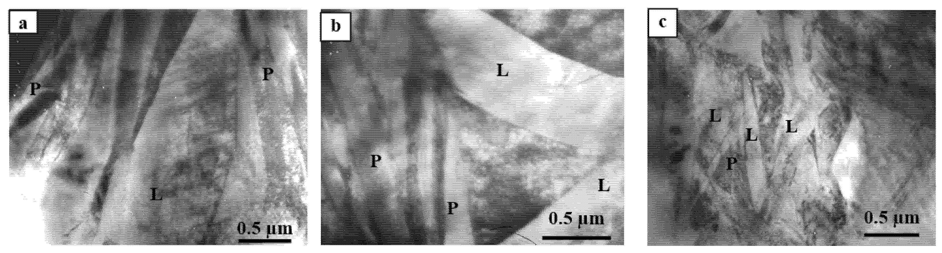
according to the morphological feature, α′-martensite in the initial state and after exposure to an electron beam is represented by lamellar and packet martensite;
-
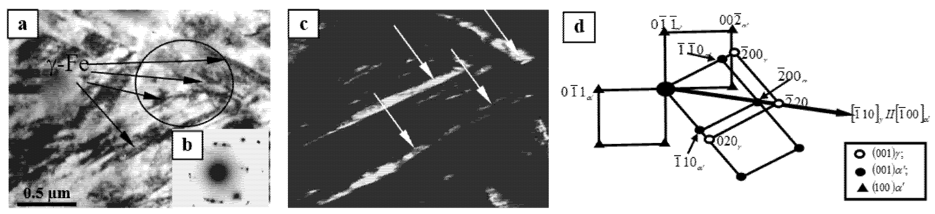
the γ—phase (residual austenite) is present inside martensitic plates in the form of twin-type colonies consisting of separate parallel thin plates with an average size of ~10 × 250 nm and a volume fraction in the material of ~6%;
-
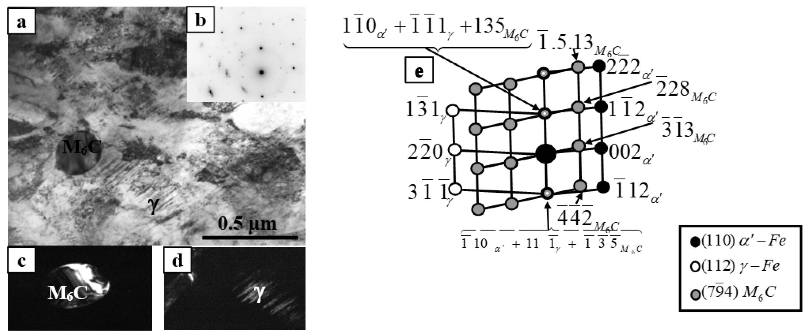
in the initial state and after exposure to the electron beam, the material also contains particles of M6C-type carbide of globular shape, which has a complex composition (Fe,W,Mo)6C, with an average size of ~0.5 microns and a volume fraction of 5%;
-
the scalar dislocation density plate and packet martensite after processing equal to the amount ρ = 4.5 × 1010 cm−2, which is 2-2. 5 times higher than in the initial state that has values for plate martensite ρ = 1.8 × 1010 cm−2 and packet martensite ~ρ = 3.5 × 1010 cm−2
-
after exposure to the electron beam, the amplitude of the internal long-range stresses equal σ = 280 MPa, and the amplitude of the shear stresses equal σL = 420 MPa, that is, the condition σL > σ is fulfilled, which confirms the plastic nature of the bending-torsion of the crystal lattice of α′-martensite.

Author Contributions

B.R. designed the experiments; A.K. and R.K. performed the experiments; L.Z. and Z.S. analyzed the data; B.R., L.Z. and Z.S. wrote, reviewed and edited the paper. All authors have read and agreed to the published version of the manuscript.

Funding

The work was performed in the framework of program-targeted funding of the Committee of Science of the Ministry of Education and Science of the Republic of Kazakhstan for 2020–2022 (AP08857579).

Institutional Review Board Statement

Not applicable.

Informed Consent Statement

Not applicable.

Data Availability Statement

Data is contained within the article.

Acknowledgments

The authors would like to thank the staff of the Laboratory for Testing Materials under the Conditions of a Thermonuclear Reactor of the National Nuclear Center (Kazakhstan) for their support in carrying out experiments on the electron irradiation of samples.

Conflicts of Interest

The authors declare that there is no conflict of interest regarding the publication of this manuscript.

References

  1. Yan, X.G.; Li, D.Y. Effects of the sub-zero treatment condition on microstructure, mechanical behavior and wear resistance of W9Mo3Cr4V high speed steel. Wear 2013, 302, 854–862. [Google Scholar] [CrossRef]
  2. Yadav, V.K.; Kumar, P.; Dvivedi, A. Effect of tool rotation in near-dry EDM process on machining characteristics of HSS. Mater. Manuf. Process. 2019, 34, 779–790. [Google Scholar] [CrossRef]
  3. Enomoto, T.; Sugihara, T.; Yukinaga, S.; Hirose, K.; Stake, U. Highly wear-resistant cutting tools with textured surfaces in steel cutting. CIRP Ann. 2012, 61, 571. [Google Scholar] [CrossRef]
  4. Kim, J.; Narayanan, T.S.N.S.; Park, H.W. Reducing the pitting susceptibility of AISI 304 stainless steel using a hybrid treatment of high-power diode laser and large pulsed electron beam irradiation. Surf. Coat. Tech. 2020, 381, 1. [Google Scholar] [CrossRef]
  5. Konovalov, S.V.; Kormyshev, V.E.; Ivanov, Y.F.; Teresov, A.D. Electron-beam processing of the hardened layer formed on Hardox 450 steel electric-wire welding system Fe-C-V-Cr-Nb-W. Lett. Mater. 2016, 6, 350. [Google Scholar] [CrossRef] [Green Version]
  6. Ormanova, M.; Petrov, P.; Kovacheva, D. Electron beam surface treatment of tool steels. Vacuum 2017, 135, 7. [Google Scholar] [CrossRef]
  7. Skakov, M.; Rakhadilov, B.; Scheffler, E.M. Microstructure and tribological properties of electrolytic plasma nitrided high-speed steel. Mater. Test. 2015, 57, 360. [Google Scholar] [CrossRef]
  8. Wang, X.; Han, X.G.; Lei, M.K.; Zhang, J.S. Effect of high-intensity pulsed ion beams irradiation on corrosion resistance of 316L stainless steel. Mater. Sci. Eng. A 2007, 457, 84. [Google Scholar] [CrossRef]
  9. Wang, R.; Cui, H.; Huang, J.; Jiang, H. Effect of the continuous electron beam process treatment in the surface modification of T10 steel. Nucl. Instrum. Methods Phys. Res. 2018, 436, 29. [Google Scholar] [CrossRef]
  10. Wang, R.; Yu, J.; Wei, D.; Meng, C. Surface microstructures and improved mechanical property of 40CrMn steel induced by continuous scanning electron beam process. Nucl. Instrum. Methods Phys. Res. B 2019, 459, 130–136. [Google Scholar] [CrossRef]
  11. Bessonov, D.A.; Vorobev, S.V.; Ivanov, F.Y. Povysheniye ustalostnoy dolgovechnosti stali 20KH13 elektronno-puchkovoy obrabotki. News Univ. Ferr. Metall. 2011, 10, 48–49. (In Russian) [Google Scholar]
  12. Ivanov, Y.F.; Gromov, V.E.; Vorobyov, S.V.; Bessonov, D.A.; Kolubaeeva, Y.A.; Konovalov, S.V. Structural-phase state of a 20CR13 steel surface layer irradiated by a high-intensity electron beam. Phys. Mesomech. 2011, 14, 111–116. (In Russian) [Google Scholar]
  13. Rykalin, N.N.; Zuev, I.V.; Uglov, A.A. Osnovy elektronno-luchevoy obrabotki materialov. Mech. Eng. 1978, 32–35. (In Russian) [Google Scholar]
  14. Denisova, Y.A. Strukturno-fazovyye prevrashcheniya v stalyakh, obrabotannykh nizkoenergeticheskim intensivnym elektronnym puchkom mikrosekundnoy dlitelnosti. Dis. K.F.M. Sci. Tomsk 2012, 220. (In Russian) [Google Scholar]
  15. Kozlov, I.V.; Popova, N.A.; Koneva, N.A. Scalar dislocation density in fragments with different substructure types. Lett. Mater. 2011, 1, 15. (In Russian) [Google Scholar] [CrossRef]
  16. Kubin, L.P.; Fressengeas, C.; Ananthakrishna, G. Collective behaviour of dislocations in plasticity. Dislocation Solids 2002, 11, 101. [Google Scholar] [CrossRef]
  17. GOST 19265-73 Bars and Strips of High-Speed Steel. Technical Specifications. GOST №. 19265-73 from 10 December 1973. Available online: http://vsegost.com/Catalog/83/8322.shtml (accessed on 22 January 2021).
  18. Guliaev, A.P. Physical metallurgy. M Metall. 1986, 6, 544. (In Russian) [Google Scholar]
  19. Tazhibayeva, I.; Kenzhin, E.; Shestakov, V.; Chikhray, Y.; Kulsartov, T.; Azizov, E.; Filatov, O.; Chernov, V. Material science activities for fusion reactors in Kazakhstan. J. Nucl. Mater. 2009, 386, 15–18. [Google Scholar] [CrossRef]
  20. Rahadilov, B.K.; Skakov, M.K.; Tulenbergenov, T.R. Structural Modification and Erosion of Plasma-Irradiated Tungsten and Molybdenum Surfaces. Key Eng. Mater. 2017, 736, 46. [Google Scholar] [CrossRef]
  21. Tulenbergenov, T.; Skakov, M.; Kolodeshnikov, A.; Zuev, V.; Rakhadilov, B.; Sokolov, I.; Ganovichev, D.; Miniyazov, A.; Bukina, O. Interaction between nitrogen plasma and tungsten. Nucl. Mater. Energy 2017, 13, 63. [Google Scholar] [CrossRef]
  22. Skakov, M.; Rakhadilov, B.; Karipbayeva, G. Specifics of microstructure and phase composition of high-speed steel R6M5. Appl. Mech. Mater. 2013, 404, 20–24. [Google Scholar] [CrossRef]
  23. Zuo, J.M.; Spence, J.C.H. Advanced Transmission Electron Microscopy. Imaging and Diffraction in Nanoscience; Springer: New York, NY, USA, 2017; p. 729. [Google Scholar]
  24. Matsukawa, Y.; Liu, G.S. In-situ TEM study on elastic interaction between a prismatic loop and a gliding dislocation. J. Nucl. Mater. 2012, 425, 54–59. [Google Scholar] [CrossRef]
  25. Hirsh, P.; Hovi, A.; Nicolson, R.; Peshli, D.; Yelan, M. Electron Microscopy of Fine Crystals; Ytevski, L.M., Ed.; Mir Publ.: Moscow, Russia, 1968; p. 574. [Google Scholar]
  26. Zisman, A.A.; Nikolaev, D.I.; Lychagina, T.A.; Yashina, E.A. On the Size Effect for Neutron Diffraction by Two-Phase Structures and Applicability of Composite Standards in Analysis of Residual Austenite in Steels. Tech. Phys. 2018, 63, 1696–1702. [Google Scholar] [CrossRef]
  27. Kozlov, I.V.; Ivanov, I.F.; Simonov, P.C. Phase composition and fine structure of R6M5 steel. Polzunovskii Alm. 2004, 4, 47–51. (In Russian) [Google Scholar]
  28. Shtremel, M.A. Prochnost splavov. Chast 1. Defekty reshetki, 3rd ed.; M.-MICIC: Moscow, Russia, 1999; p. 384. (In Russian) [Google Scholar]
  29. Ivanov, Y.F.; Gromov, V.E.; Glezer, A.M.; Peregudov, O.A.; Morozov, K.V. Nature of the structural degradation rail surfaces during operation. Bull. Russ. Acad. Sci. Phys. 2016, 80, 1483–1488. [Google Scholar] [CrossRef]
  30. Lipson, H.; Petch, N.J. The crystal structure of cementite Fe3C. J. Iron Steel Inst. 1940, 142, 95–103. [Google Scholar]
  31. Dunđer, M.; Vuherer, T.; Samardžić, I. Analysis of heat-affected zone microstructures of steel P92 after welding and after post-weld heat treatment. Int. J. Adv. Manuf. Technol. 2019, 102, 3801–3812. [Google Scholar] [CrossRef]
  32. Le, K.C.; Piao, Y. Thermodynamic dislocation theory: Size effect in torsion. Int. J. Plast. 2019, 115, 56–70. [Google Scholar] [CrossRef] [Green Version]
  33. Kormyshev, V.E.; Ivanov, Y.F.; Gromov, V.E. Formation of Fine Surface of Long Rails on Differentiated Hardening. J. Synch. Investig. 2020, 14, 1187–1190. [Google Scholar] [CrossRef]
  34. Koneva, N.A.; Popova, N.A.; Nikonenko, E.L. Internal Stresses and their Sources in BCC and FCC Steels. Solid State Phenom. 2020, 303, 128–142. [Google Scholar] [CrossRef]
Figure 1. TEM—images of the fine structure of R5M5 steel in the initial state (α′-martensite: P—packet martensite, L—lamellar martensite), showing plate martensite, which represents lens-shaped crystals (a), crystals grouped in the form of “zigzags” (b), small packets of slats in the steel, which are located in areas of grain with small martensitic plates (c). The initial state α′-martensite: P—packet martensite, L—lamellar martensite.
Machines 09 00024 g001
Figure 2. Interlayers of residual austenite (γ-phase) along the boundaries of martensitic battens in R6M5 steel in the initial state (a)—bright-field image; (b)—microdiffraction pattern; (c)—dark-field image obtained in the reflex [020]γ; (d)—the indicated microdiffraction pattern.
Machines 09 00024 g002
Figure 3. TEM images of the fine structure of R6M5 steel with identified carbides (a)—the bright-field image of M6C type carbide particles; (b)—the bright-field image, (c,d)—the microdiffraction pattern and its indicated pattern.
Machines 09 00024 g003
Figure 4. TEM image of the location of vanadium carbide in R6M5steel (a)—the bright field image; (b)—microdiffraction pattern; (c)—the indicated microdiffraction pattern, (d)—the dark-field image obtained in the VC carbide reflex (marked by arrows).
Machines 09 00024 g004
Figure 5. TEM images of the fine structure of R6M5 steel after impacts by an electron beam (ac)—bright-field images; (d)—microdiffraction pattern and (e)—indicated scheme.
Machines 09 00024 g005
Figure 6. TEM—images of residual austenite and carbide in steel R6M5 after impact by an electron beam (a)—bright-field image; (b)—microdiffraction pattern; (c)—a dark-field of M6C carbide; (d)—the dark-field image of residual austenite; (e)—the indicated microdiffraction pattern.
Machines 09 00024 g006
Table 1. Quantitative characteristics of the dislocation structure of morphological components of the α-phase of R6M5 steel before and after impact by an electron beam (electron microscopy data of the sample surface).
PhaseThe Average Quantitative Parameters of Fine Structure
PVρ, cm−2ρ ±, cm−2χ, cm−1σ, MPaσL, MPa
After surface irradiation
Packet martensite10%4.5 × 10102 × 1010500280420
Lamellar martensite90%
Initial state
Packet martensite80%3.5 × 10101.7 × 1010436260350
Lamellar martensite20%
Note: PV—volume fraction; ρ-scalar dislocation density; ρ ± —the excess density of dislocations; χ—the amplitude of the torsion curvature of the crystal lattice; σL—shear stress; σ—moment internal stresses.
Publisher’s Note: MDPI stays neutral with regard to jurisdictional claims in published maps and institutional affiliations.

