Article

Evaluation of Grip Force and Energy Efficiency of the “Federica” Hand

1
Department of Electrical Engineering and Information Technologies, Polytechnic and Basic Sciences School, University of Naples “Federico II”, 80125 Naples, Italy
2
Department of Neurorehabilitation, IRCCS Istituti Clinici Scientifici Maugeri, 27100 Pavia, Italy
3
Department of Industrial Engineering, Polytechnic and Basic Sciences School, University of Naples “Federico II”, 80125 Naples, Italy
4
School of Computing, Engineering and Mathematics, Western Sydney University, Penrith 2747, Australia
5
Department of Chemical, Materials and Production Engineering, Polytechnic and Basic Sciences School, University of Naples “Federico II”, 80125 Naples, Italy
*
Authors to whom correspondence should be addressed.
Machines 2021, 9(2), 25; https://doi.org/10.3390/machines9020025
Submission received: 29 December 2020 / Revised: 22 January 2021 / Accepted: 23 January 2021 / Published: 27 January 2021
(This article belongs to the Section Robotics, Mechatronics and Intelligent Machines)

Abstract

:
The actual grip force provided by a hand prosthesis is an important parameter to evaluate its efficiency. To this end, a split cylindrical handlebar embedding a single-axis load cell was designed, 3D printed and assembled. Various measurements were made to evaluate the performances of the “Federica” hand, a simple low-cost hand prosthesis. The handlebar was placed at different angular positions with respect to the hand palm, and the experimental data were processed to estimate the overall grip force. In addition, piezoresistive force sensors were applied on selected phalanxes of the prosthesis, in order to map the distribution of the grasping forces between them. The electrical current supplied to the single servomotor that actuates all the five fingers, was monitored to estimate the force exerted on the main actuator tendon, while tendon displacement was evaluated by a rotary potentiometer fixed to the servomotor shaft. The force transfer ratio of the whole system was about 12.85 %, and the mean dissipated energy for a complete cycle of closing-opening was 106.80 Nmm, resulting lower than that of many commercial prostheses. The mean grip force of the “Federica” hand was 8.80 N, that is enough to support the user in many actions of daily life, also considering the adaptive wrapping capability of the prosthesis. On average, the middle phalanges exerted the greatest grip force (2.65 N) on the handlebar, while the distal phalanges a force of 1.66 N.

1. Introduction

Grip force is an important parameter to evaluate performances and functionalities of both human and prosthetic hands. It is a kinetic measurement that aims to provide information about the maximum force exerted by the hand, its payload capabilities and resistance to pulling or pushing forces during grasp actions [1]. For prosthetic hand, grip force is mainly function of the mechanical system that transfers the energy from the actuators to the grasped object. Generally, prostheses exhibit different grip forces depending on the size and the shape of the object, besides the force required to hold an object is highly related to the friction between the fingers and the object [2].
In recent years, different grip force measurement systems have been presented and they are principally classified into mechanical, strain gauge and force sensors devices. Split cylindrical handlebars equipped with sensors mounted between the two halves, are often used to measure the internal force transmission of a power grasp [1]. A study presented a grip-measuring device for neuro-rehabilitation, made of a split cylinder handlebar containing a single axis load cell, with the aim to improve the patient’s ability to modulate the grasp force [1]. The “Yale Multigrasp Hand” prosthesis showed a power grasp of 23 N, measured by means of a load cell placed through the actuation tendon and another between fingers [3]. Grip performances of the “KIT Prosthetic Hand” were evaluated by using split cylinders with diameters of 31 mm and 49 mm, containing a six degrees of freedom (DOFs) force/torque sensor (Mini 40, ATI Industrial Automation®), that revealed a power grasp of about 24 N [4]. Grasp force tests of the “Soft Hand Prosthesis”, were performed by means of a force/torque sensor (Nano 25, ATI Industrial Automation®) positioned inside a split cylindrical handlebar [5]. A multi-axis dynamometer was also presented with the purpose to evaluate the grip force of human hands in a range between 5 and 250 N. The device consists of three aluminum beams covered by caps to form a cylindrical shape. Two of the beams are instrumented with strain gauges configured as full Wheatstone bridges, while the third is a static reference beam [6].
However, in addition to cylindrical handlebars mainly used for power grasp measurements, sensorized spheres were also proposed for evaluation of tripodal grip forces (grip with thumb, index and middle finger), while flat devices were usually used to measure the pressure generated by each single finger [7]. Other studies have instead focused on mapping the local forces in specific points of both the natural and prosthetic hand (e.g., phalanges) via tiny force sensors. An example of punctual forces measurement was proposed for “The Kit Prosthetic Hand”: optoforce sensors (OMD-10-SE-10N, eMageWorks Pte Ltd., Singapore) were attached to the distal phalanges of the prosthetic fingers [4]. Tekscan® company proposes the “Grip™ System”, consisting of a matrix of force sensors positioned over specific location of the fingers or the hand palm, with the aim to evaluate static and dynamic forces of human hand while grasping objects [8]. Tiny Force Sensor Resistors (FSRs) [9] attached to specific points on the hand palm and phalanxes, were also used to evaluate force distribution patterns of natural and prosthetic hands [1,10,11]. In particular, a study used customized FSRs applied on 20 predefined positions of the hand, showing total grasp forces of 16.7 N for a human hand, 21.3 N for an adaptative grip prosthesis and 47.4 N and 28.5 N for the commercial non-adaptative prosthetic hands “Sensor-hand” and “System-electro-hand” by Ottobock® respectively [12].
Adaptive prosthetic hands are generally realized by means of underactuated mechanisms (less actuators than DOFs), this is achieved by reducing the number of active DOFs motors without sacrificing the ability to conform to irregular shaped objects [13,14,15]. Adaptive prostheses, by mimicking the grasp skill of the natural hand, are able to hold objects using lower forces compared to non-adaptive grippers [12]. If the gripper is able to wrap around objects and maintain a wide contact area, grip force can be kept below 10 N to perform many actions of daily life. Conversely, non-adaptive grippers exert grip forces on small contact areas and need forces 3 to 6.5 times greater than those of adaptive devices [7]. Design of adaptive prostheses should resemble the adaptive grip of the natural hand, that is capable to conform to the shape of an object, thanks to its 22 degrees of freedom and to the compliance of the skin and tissue. The contact forces in human hand cover a large area and the grip is very efficient, since little energy is required for stable holding of an object [12]. Another study proposed an estimation of the grip force by measuring the current absorption of the prosthesis actuator. The current absorbed by the motor is proportional to the torque generated and, in turn, to the tendon traction force and to the gripping force; however, friction must be taken into account [5].
In this study, different performance analyses are presented, which were carried out on a 3D printed, low-cost, anthropomorphic, underactuated prosthetic hand, named “Federica” [10,13,16,17,18,19]. In particular, the following issues were addressed: evaluation of the grip force, by means of a sensorized handlebar; mapping of the forces exerted by the phalanxes, via custom force sensors [20,21]; measurement of the force transfer ratio of the overall mechanical system; estimation of the work required for hand closing-opening and of the dissipated energy per cycle, through measurements of the force and the displacement of the main actuator tendon of the prosthesis.

2. Materials and Methods

This section presents: a custom grip force measurement, consisting of a 3D-printed cylindrical handlebar that embeds a single-axis load cell; the mapping of the individual forces exerted by phalanxes on the handlebar, by using thin force sensors; the mechanical system of the prosthesis and an estimation of its force transfer ratio; the methodology used to estimate the work required and the dissipated energy for a hand closing-opening cycle; the experimental grip test setup.

2.1. Grip Force Measurement System

Methods for evaluating the performances of prosthetic hands, are in detail explained by the National Institute of Standards and Technology (NIST) [22]. According to the NIST guidelines, in order to measure the internal force transmission during the power grasp, it is suggested to use split cylinder handlebars, containing one or more load cells. If a handlebar capable of measuring the force along one direction only is used, it is recommended to take measurements along orthogonal directions to provide a more accurate estimate of the actual forces. The final grip force measure is obtained by computing the L2 norm of the two orthogonal components recorded.
In this study, in order to evaluate the grip force exerted by the “Federica” hand, a single axis load cell was fixed inside a custom 3D printed handlebar, consisting of two half-cylinders. In particular, the two ends of the load cell were screwed to the two half-cylinders by placing half-centimeter spacers (see Figure 1), so that the grip force applied to the handlebar should be completely transferred to the load cell.
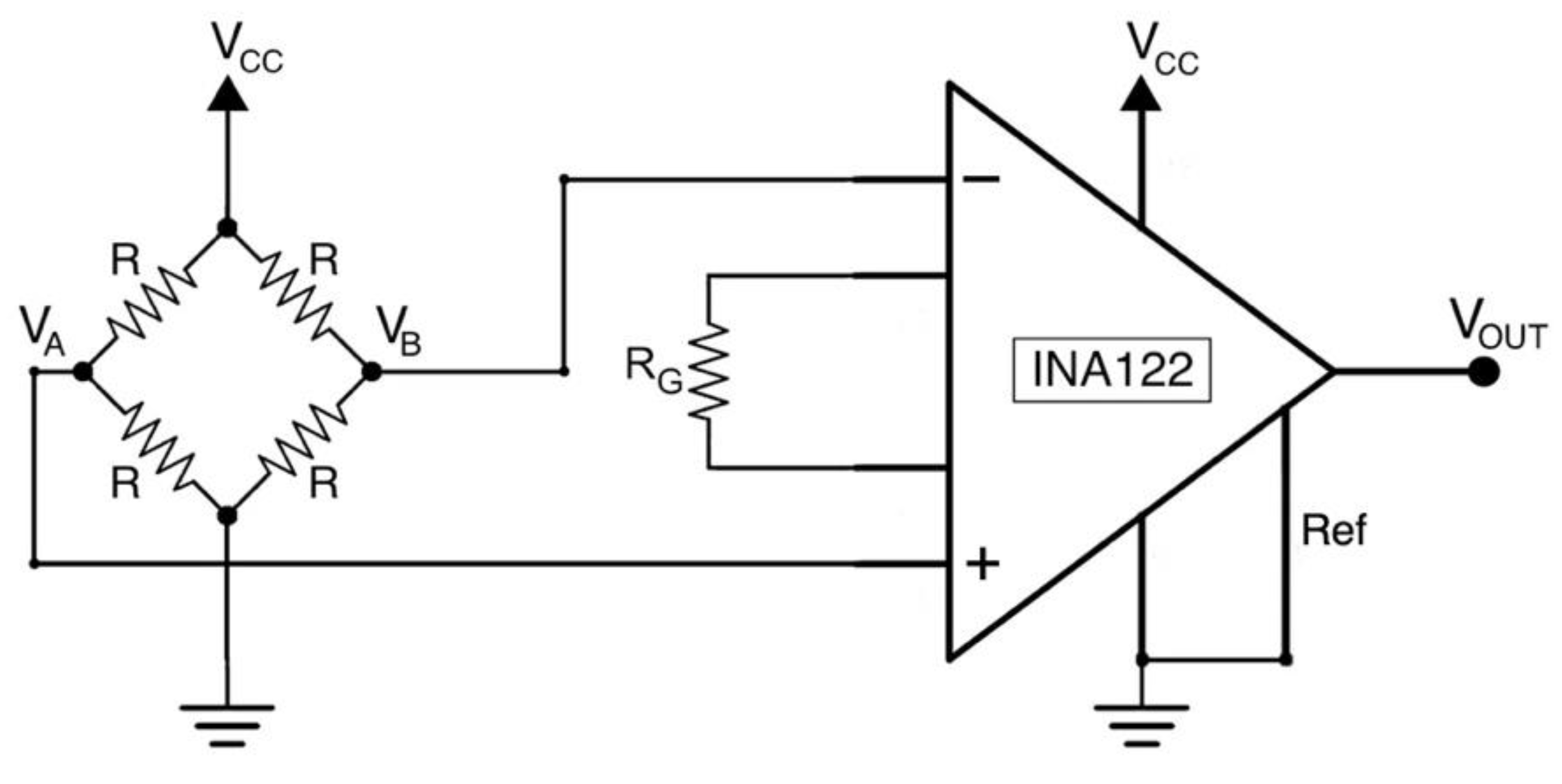
The single axis load cell consists of an aluminum bar with four strain gauges glued on it, those are connected to form a full Wheatstone bridge circuit (minimizing the effect of temperature). All the gauges exhibit at rest a value of 1 kΩ and two of them are wired in compression, while the other two in tension, so as to make the measuring circuit insensitive to temperature variations. The bridge output voltage was acquired by means of a INA122 instrumentation amplifier [23], the gain resistor RG was set to 500 Ω (see Figure 2), providing a gain of 405 V/V.
The equation describing the output voltage from the load cell conditioning circuit is presented below (R = 1 kΩ, RG = 500 Ω, Vcc = 5 V, G = 405):
V OUT = G (   V A   V B ) = G   Δ R R   V CC
A static calibration of the sole load cell was carried out by fixing one end of it to a table and applying 12 calibrated weights in suspension to the other end. The output voltages corresponding to the different weights were used to perform a static calibration of the load cell.
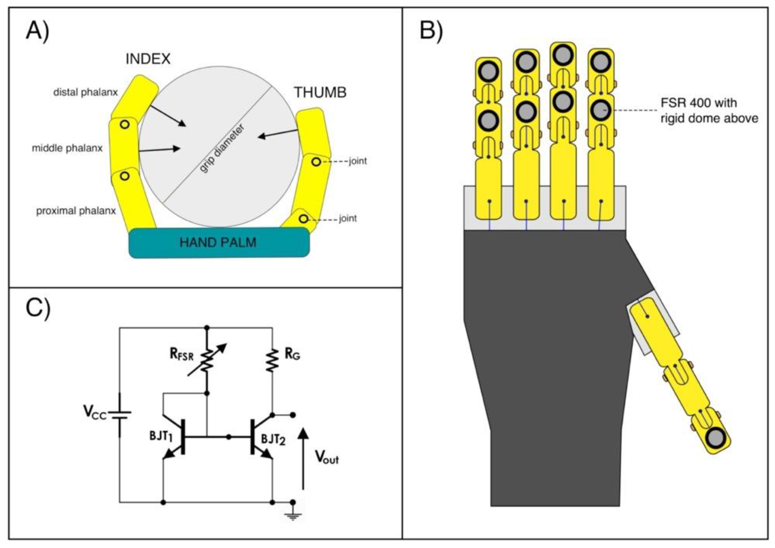
Due to the geometry of the hand prosthesis and the diameter of the handlebar (see Figure 3A), only the distal phalanx of the thumb and the distal and medium phalanges for the index, middle, ring and little finger, take actually contact with the handlebar. The combination of these 9 forces along the sensing direction of the load cell, provides the definitive power grip force. Tiny piezoresistive force sensors [20,21] were applied on the phalanges involved in the grasp (see Figure 3B), in order to measure the forces exerted by each phalanx during the grasping task. Force Sensitive Resistors (FSR) by Interlink Electronics (FSR 400 model) were used; on their sensing areas, rigid domes were attached to facilitate mechanical coupling with the grasped object. As in previous studies [17,21], the FSRs were conditioned by means of current mirror circuits (see Figure 3C). Basically, each circuit (designed to sense forces in the range 0–10 N) replicates the FSR current in the gain resistor RG, thus providing an output voltage VOUT proportional to the measured force. Static calibrations were performed to obtain the FSRs sensitivities: different calibrated weights were applied on the active area of the sensors (perpendicular to the dome) and the corresponding output voltages from the conditioning circuits were recorded, after, linear regressions provided the force–voltage relationships.

2.2. Prosthetic Mechanical System and Its Force Transfer Ratio

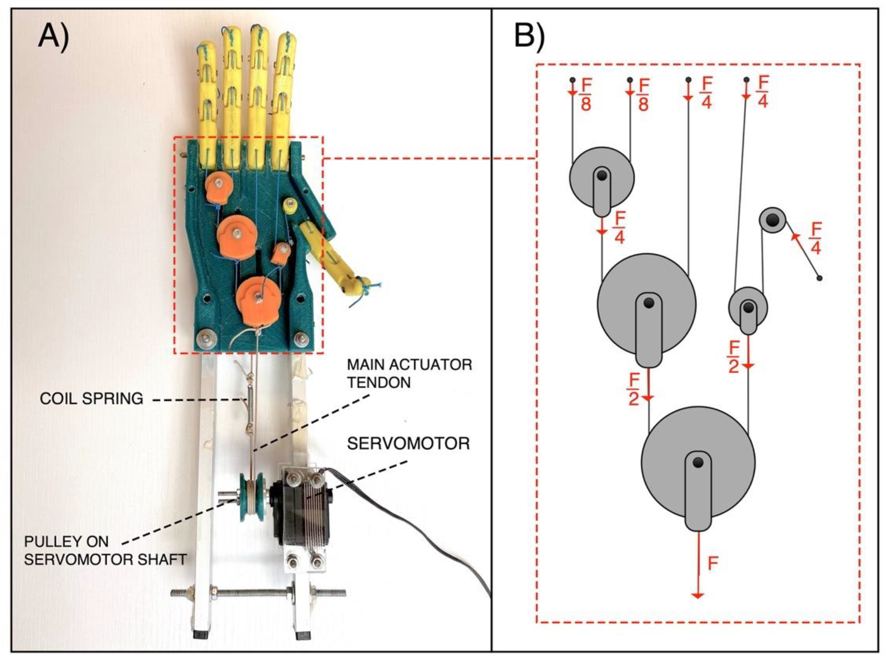
The “Federica” hand is equipped with five fingers and allows to perform the grasp function, auto-adapting the phalanxes around objects of any shape [16,19]. It is strongly underactuated as a single servomotor (Hitec HSR-5990TG [24]) provides to move the fifteen phalanxes (15 DOFs). The motion of the servomotor is synergistically given to the fingers by means of inelastic cables (tendons). A differential mechanical system of pulleys distributes the force exerted by the servomotor on each finger in predefined percentages (see Figure 4). In particular, the force F exerted by the motor on the main actuator tendon is distributed to the fingers always in the same proportions: a quarter of the whole force ( F /4) is applied to the middle finger, index finger and thumb; while one eighth ( F /8) of the force is applied to the ring finger and little finger. This specific force distribution is aimed at ensuring an effective grip, regardless of the particular hand configuration.
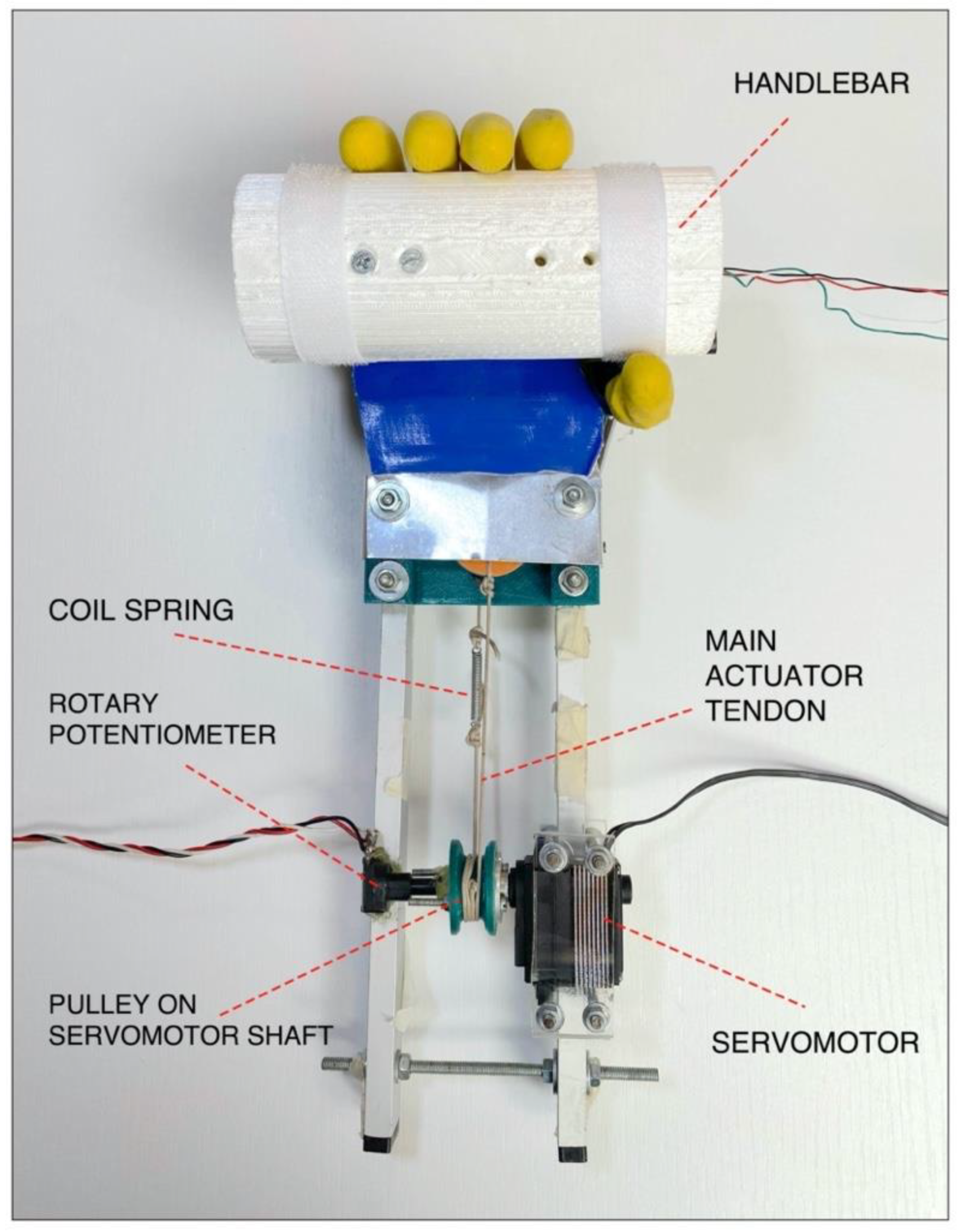
The tendons form a closed loop and are wrapped around the motor pulley, from which a main tendon for closing the hand and one for opening originate. The pulley is connected to the servomotor shaft, so that when the servomotor turns in one direction, one main tendon is pulled and the other is released and vice-versa. A little coil spring (elastic constant K ≈ 2.5 N/mm) is inserted along the back-side main tendon, in order to allow the complete flexion of the fingers, otherwise not possible using inextensible cables. The current prototypal version of the “Federica” hand is provided with a rigid handle mounted on its back, while two aluminum bars are used to remotely fix the servomotor.
Proportional control of hand closure is achieved by measuring the contraction of residual limb muscles by means of a muscle force sensor [20], replacing the EMG. A simple Arduino board was adopted as processing unit. More detailed information about the “Federica” hand can be found in [10,13,16,17,18]; demonstration videos are also available at the dedicated webpage [19].
Figure 5 shows “Federica” hand while grasping the custom handlebar. During the experimental tests, the prosthesis palm was covered with an aluminum plate and a rotary potentiometer was fixed to the pulley on the servomotor output shaft, in order to measure its rotation.
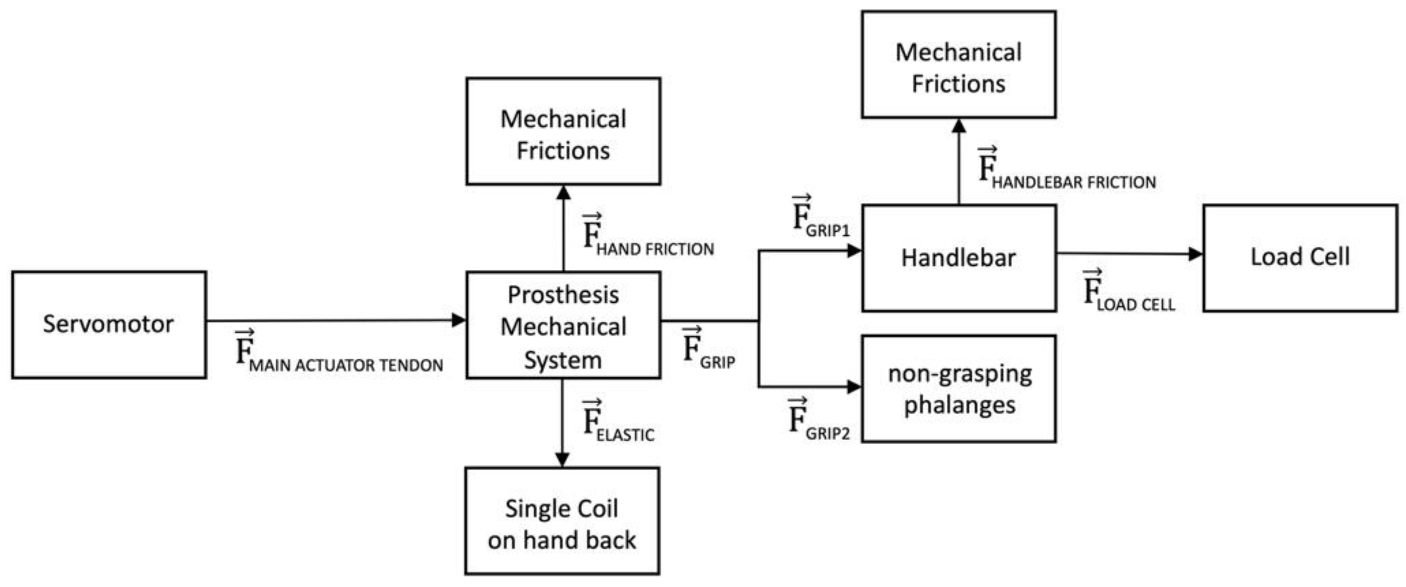
Figure 6 shows the flow of forces generated by the servomotor on the main actuator tendon ( F MAIN ACTUATOR TENDON) through the mechanical system. This tensile force is distributed to the phalanges ( F GRIP) via the differential system of pulleys, partly lost by mechanical friction ( F HAND FRICTION), and partly absorbed as elastic force ( F ELASTIC) by the sole spring in the back main tendon. The grip force is the sum of the forces ( F GRIP1) exerted on phalanges in direct contact with the grasped object. Instead, the forces ( F GRIP2) applied on the free phalanges are not used in the prehension. The effective grip force ( F LOAD CELL) that reaches the load cell in the handlebar, is represented by the F GRIP1 minus the little friction force generated inside the handlebar ( F HANDLEBAR FRICTION).
The Force Transfer Ratio was computed as the ratio between the force developed by the hand on the handlebar ( F LOAD CELL) and the pulling force applied on the main actuator tendon ( F MAIN ACTUATOR TENDON), that is:
Force   Transfer   Ratio = F LOAD   CELL   F MAIN   ACTUATOR   TENDON

2.3. Estimation of Main Tendon Force from Servomotor Current Absorption

A current measurement circuit based on the INA169 [25] was used to continuously monitor the current absorbed by the servomotor by the battery. Figure 7 shows that the motor load current IS is drawn from the voltage generator VIN through the 0.1 Ω shunt resistor RSHUNT. The INA169 converts the differential input voltage across RSHUNT to a current output. This current is converted back to a voltage VOUT with an external load resistor RL that provides a predefined gain. The transfer function for the current measurement amplifier is:
V OUT   =   I O   R L     =   g m   I S   R SHUNT   R L
where gm is 1000 μA/V, RSHUNT is 0.1 Ω and RL is 9.35 kΩ, for VIN = 7.4 V (RL is variable and related to the input voltage VIN). Therefore, measuring the circuit output voltage VOUT is possible to obtain the current flowing in the load (i.e., the servomotor).
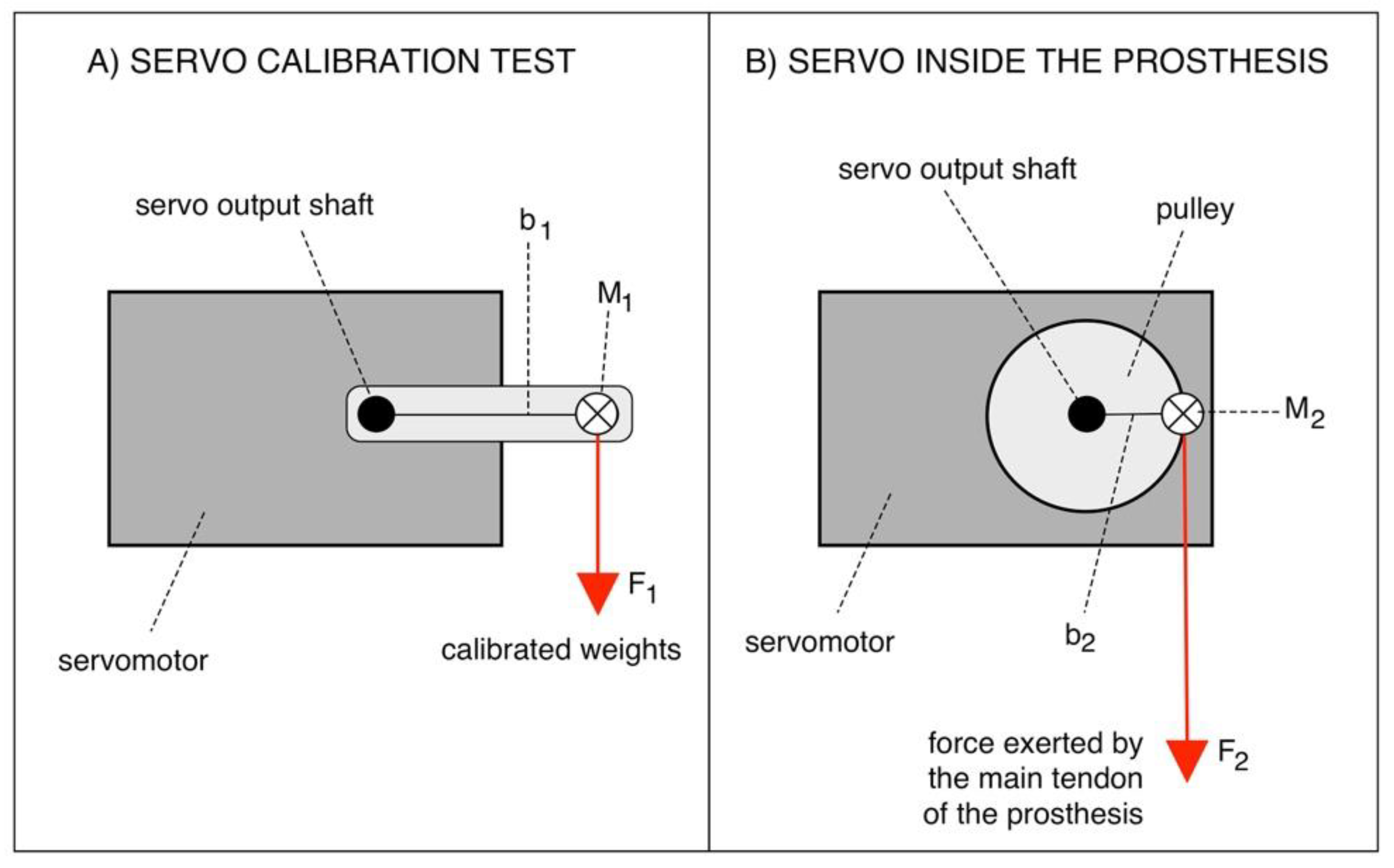
The relationship between the absorbed current and the torque generated by the servomotor [16] was estimated experimentally. The servomotor was fixed on a large table (see Figure 8A), different calibrated weights were applied in suspension on its arm and the related absorbed current were recorded. The torque [Ncm] was computed by multiplying the weight (expressed in N) by the length of the servomotor arm (2.5 cm). The linear regression of the experimental data provides the current–torque relationship. “Federica” hand operates with a 2 cm diameter pulley connected to the servomotor shaft (see Figure 8B).
Figure 8 shows that for the same torque, the force (F2) exerted by the main tendon of the prosthesis is given by the following relationship:
M 1   =   M 2 F 1 b 1   =     F 2 b 2     F 2 =   F 1 b 1 b 2
By considering that b 1 = 2.5 cm and b 2 = 1 cm, F 2 = M 1 . Thus, by correlating the current absorption to the mechanical torque generated by the servomotor, it is possible to estimate the force exerted on the main tendon of the prosthesis.

2.4. Estimation of Main Tendon Displacement

A rotary potentiometer was fixed on the servomotor shaft (see Figure 5) to measure the angular rotation of the servomotor and, in turn, the main tendon displacement. The potentiometer was connected as a voltage divider of the 5 V supply voltage. The relationship between the shaft rotation angle and the potentiometer output voltage, was experimentally obtained by considering various known angular positions (18 degrees step) and measuring the corresponding displacements of the main tendon.

2.5. Estimation of Work

The work needed to operate the “Federica” hand (e.g., to close and open the hand) can be computed by knowing the force exerted by the main tendon and the path length where this force is acting (i.e., tendon displacement) [26,27]. The amount of work corresponds to the area under the force-displacement curve, as explained in the equation 5 (W: work [Nmm]; x: tendon displacement [mm]; L: maximum tendon displacement [mm]; F: force as function of tendon displacement [N]):
W = 0 L F ( x ) d x

2.6. Experimental Grip Tests with the Load Cell in Different Positions

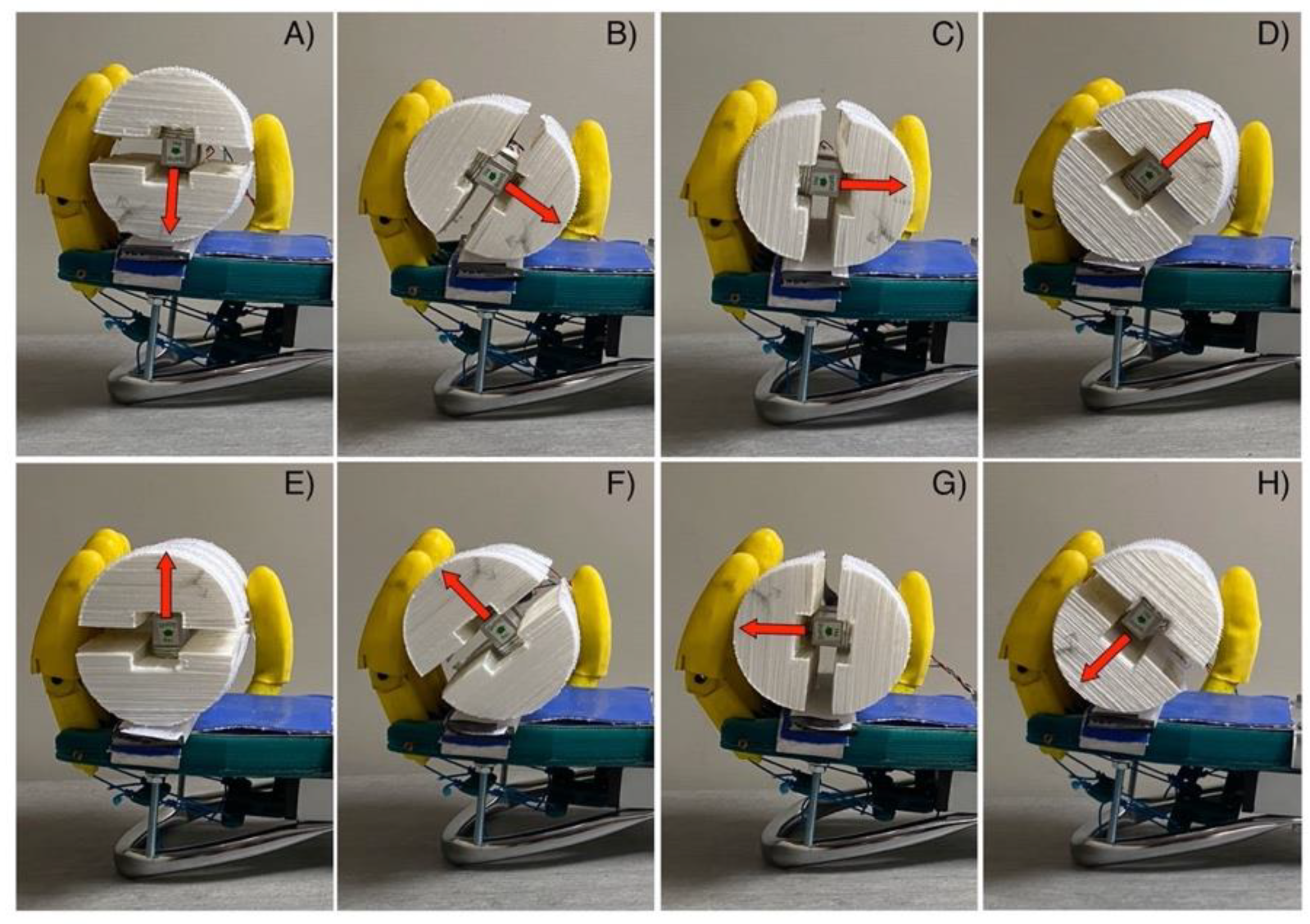
Simultaneous acquisitions of the servomotor current and of the force detected by the handlebar, were carried out while the “Federica” hand gripped the handlebar. The signals were acquired at 1 kHz sampling frequency with 14-bit precision by means of an acquisition board (NI USB-6009, National Instruments, Austin, Texas, USA). The servomotor current signal was low-pass filtered with a Butterworth 3-rd order filter, 10 Hz cut-off frequency, to obtain a short-time averaged absorption, less affected by instantaneous current peaks typical of servomotors (see [18] for details). Since the handlebar senses force only along one axis, eight different angular positions (45 degrees increments: see Figure 9) of the handlebar with respect to the prosthesis palm were considered. Averages over the eight redundant measurements provide a better estimate of the gripping force components.

3. Results

This section shows the results of the experimental calibrations of the load cell embedded in the handlebar; the custom force sensors applied on prosthesis phalanxes; the servomotor (current vs torque); the rotary potentiometer. Afterward, the main findings of the grip force test, as well as the work and the hysteresis of a hand closing–opening cycle are presented.

3.1. Load Cell Static Calibration

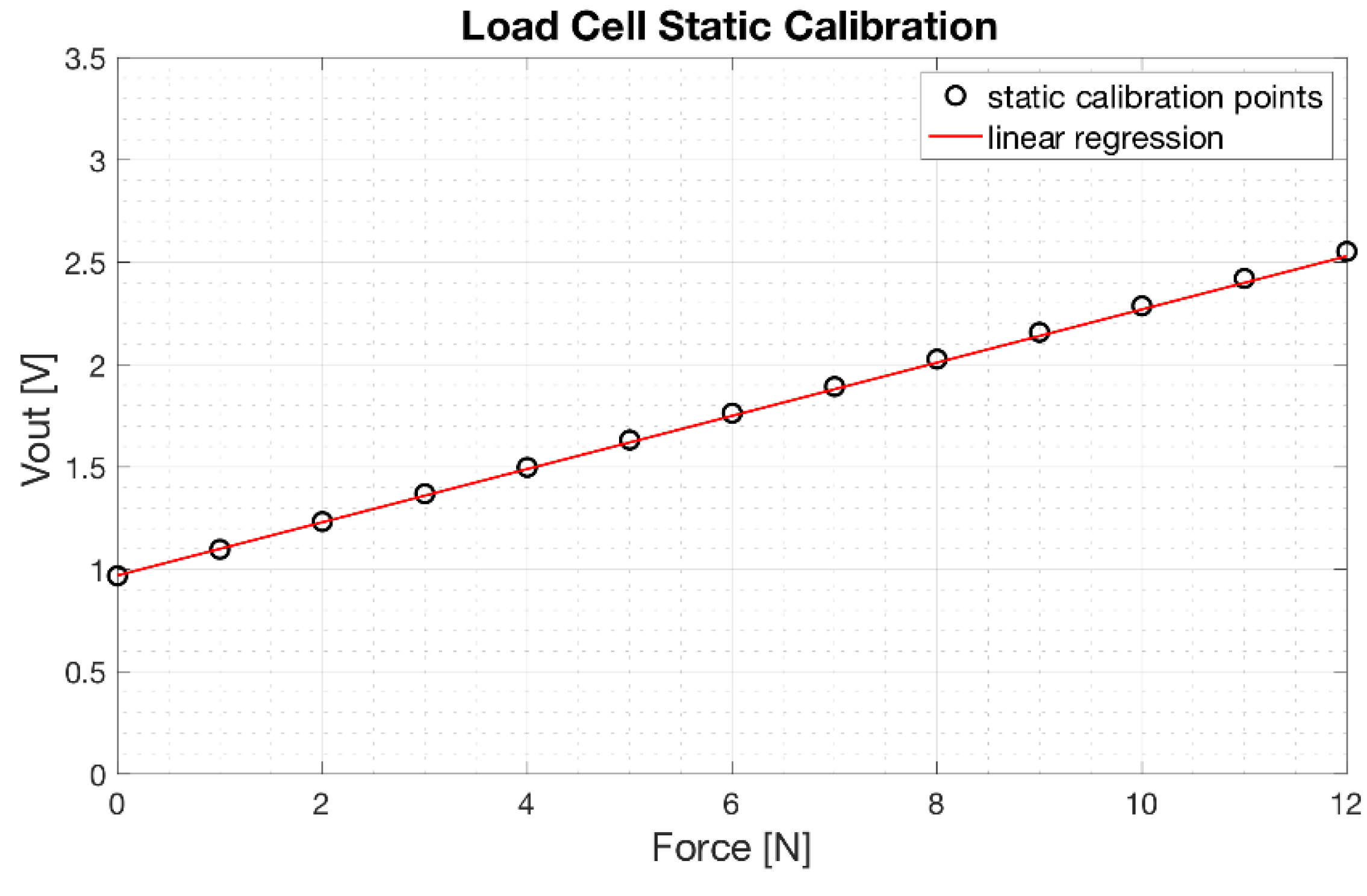
The results of the static calibration of the load cell are presented in Figure 10. The experimental measurements are represented as circles while the linear regression is represented as a continuous red line. The angular coefficient of the regression line was 0.13 [V/N], whereas the coefficient of determination R2 of the linear regression was 0.99, proving a linear behavior of the load cell.
The equation which allows to estimate the force [x] applied to the load cell as a function of its voltage output [y] (see Figure 2) is:
y   [ V ] =     0.13   ×   x   [ N ]   +   0.97

3.2. FSRs Static Calibrations

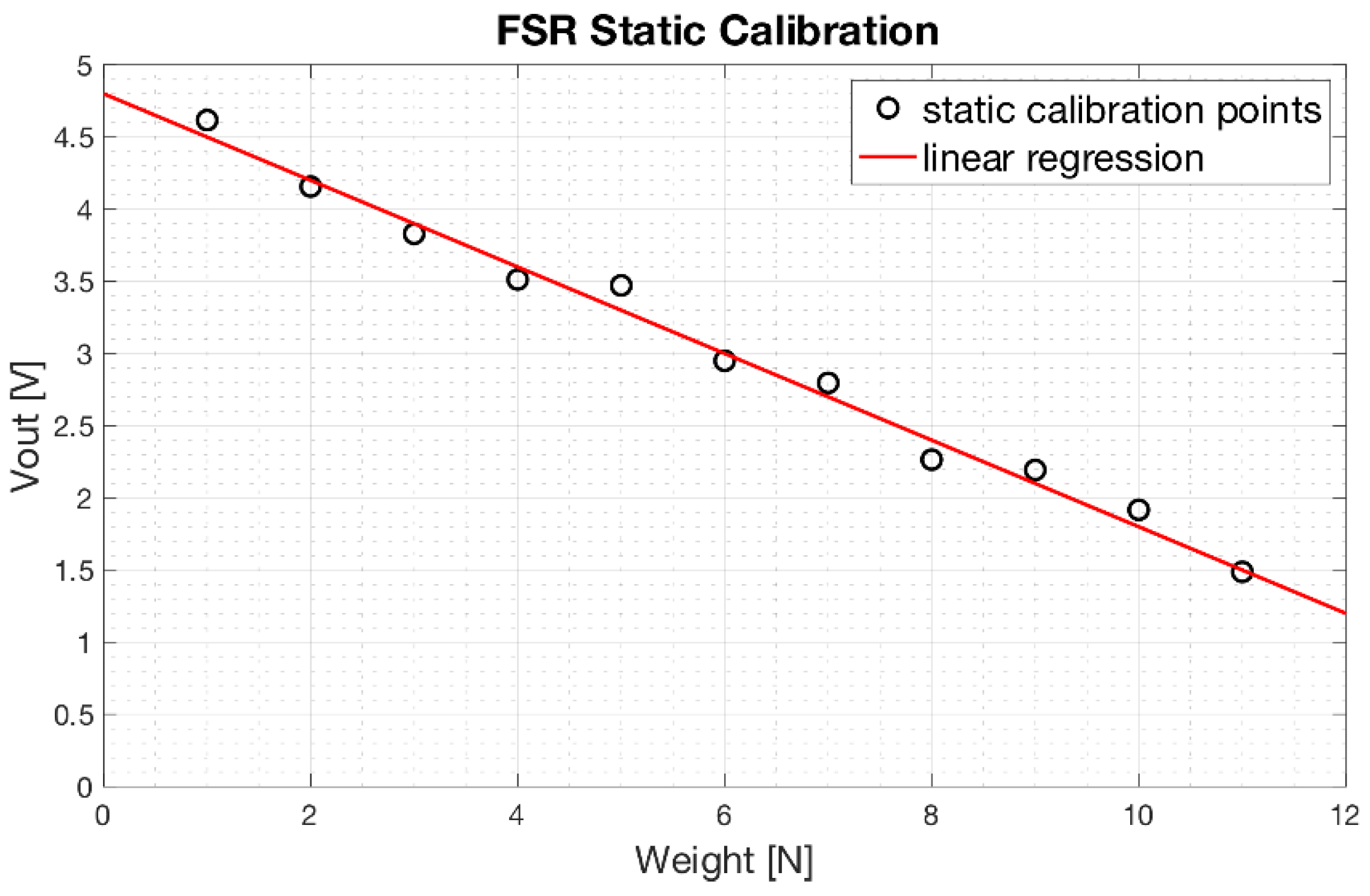
Results of the static calibration related to an FSR-based sensor applied on a prosthesis phalanx, are showed in Figure 11. Experimental measurements are represented as circles, while linear regression is represented as red continuous line. The regression line is expressed as:
y   [ V ]   =   0.297 ×   x   [ N ] +   4.80  
with a coefficient of determination R2 equal to 0.99. Similar results were obtained from the FSR-based sensors applied on the other phalanges.

3.3. Servomotor Characterization

Figure 12 shows the experimental data of the current absorbed as a function of the mechanical torque provided by the servomotor. Experimental measurements are represented as black circles, while the polynomial regression is represented as a red continuous line. The relationship is clearly non-linear. However, a simple 2nd order polynomial function well fits the current-torque experimental data with a coefficient of determination R2 equal to 0.983.
The equation of the 2nd order polynomial regression function resulted:
y [ mA ]   =   42.49   +   12.05 × x   [ Ncm ]   0.03 × x 2   [ Ncm ]
From the relationship (8), it is possible to estimate the torque exerted by the servomotor from the instantaneous measurement of the absorbed current. In turn, by considering the arm of the motor pulley of the prosthesis, the force exerted on the main tendon can be continuously estimated by the servomotor current (see Section 2.3).

3.4. Rotary Potentiometer Calibration

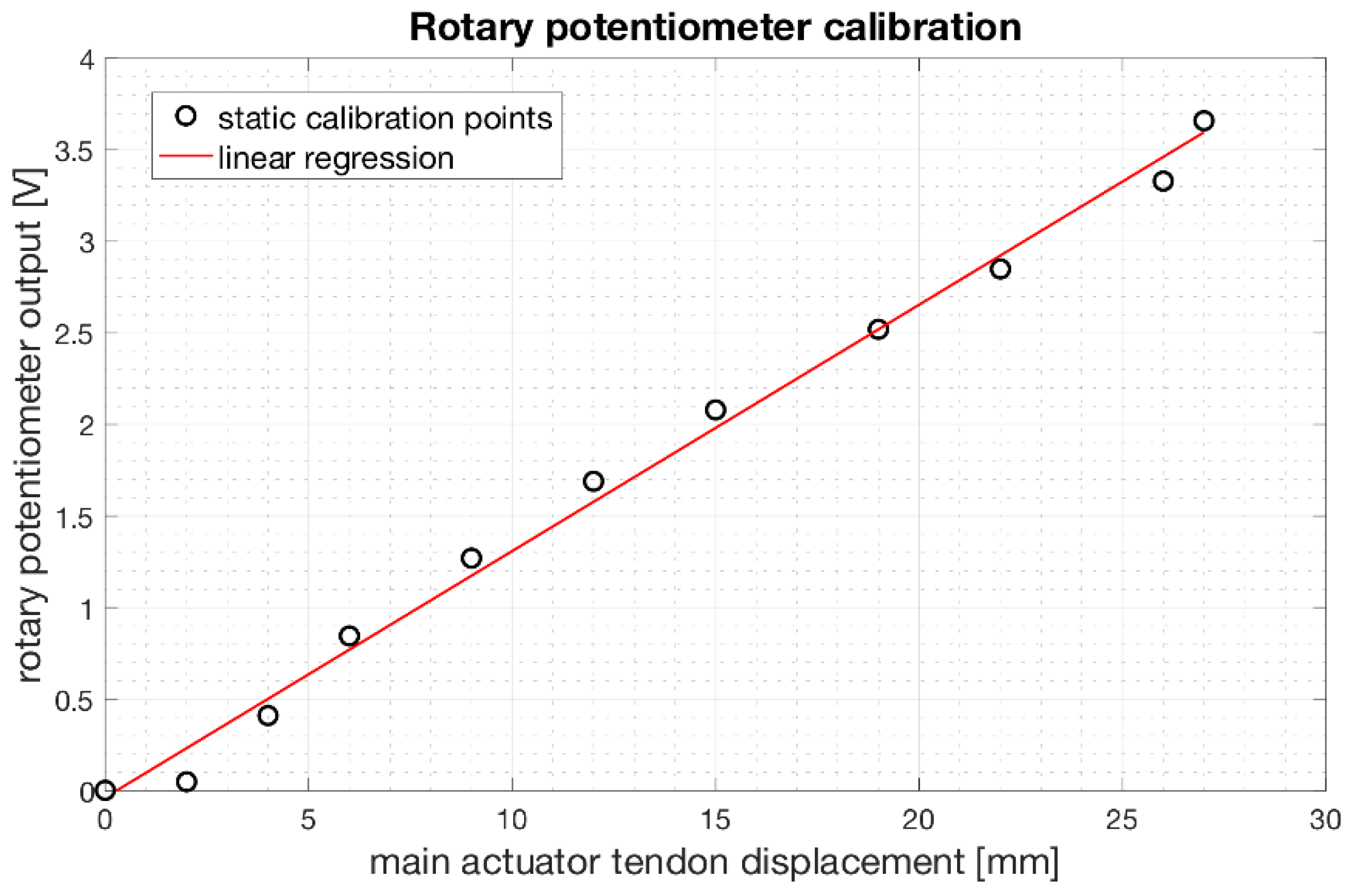
Figure 13 shows the trend of the output voltages from the rotary potentiometer fixed to the servomotor shaft as a function of the main actuator tendon displacement. The linear regression function well fits the experimental data with a coefficient of determination R2 equal to 0.99.
The linear regression function resulted:
y   [ V ]   =   0.135   ×   x   [ mm ]     0.037
From the relationship (9), it is possible to estimate the main actuator tendon displacement in function of the output voltage from the potentiometer.

3.5. Results of the Experimental Grip Tests

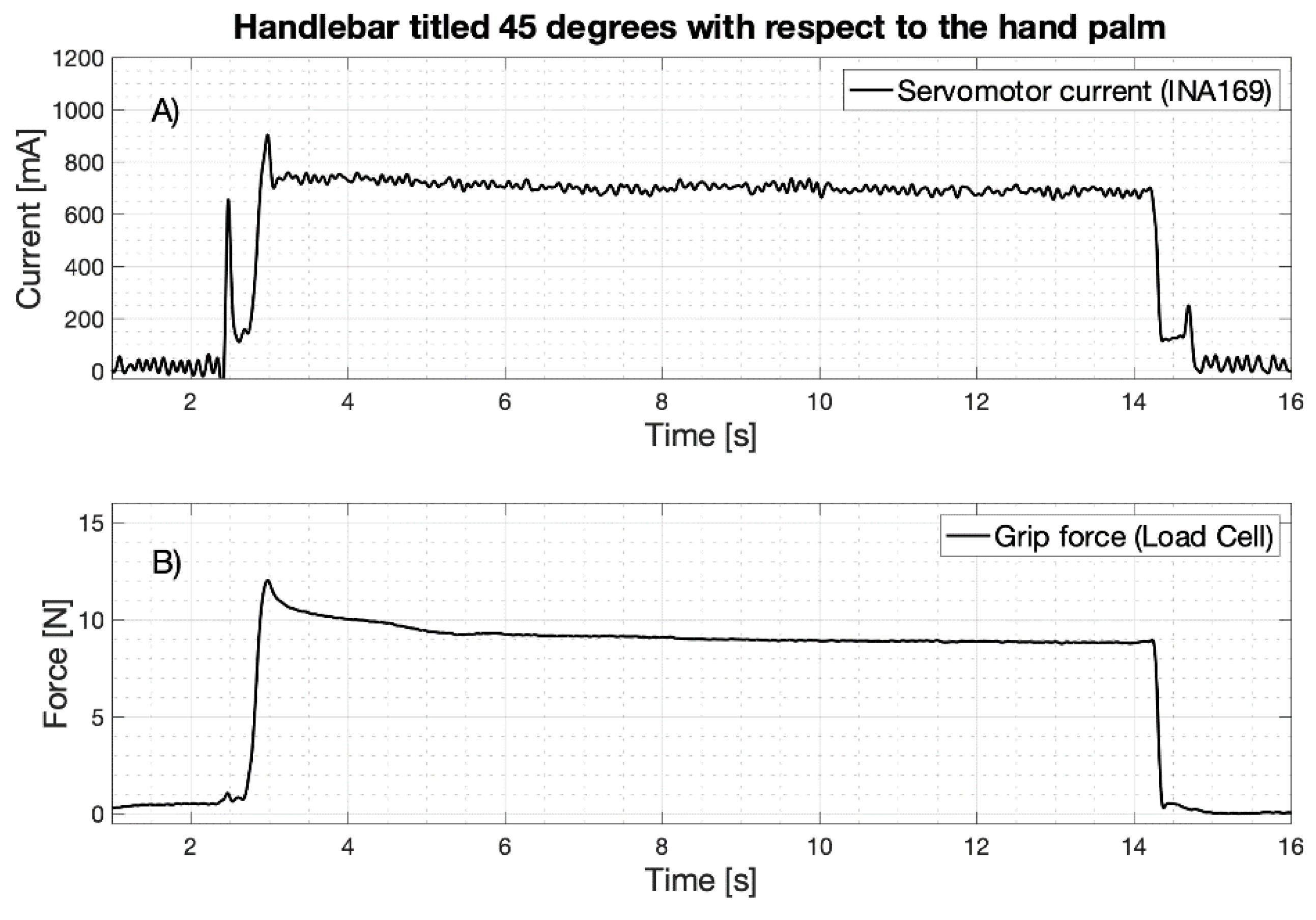
As an example of the grip test experimental data, Figure 14 shows simultaneous recordings of the motor current absorption (mA) and the grip force (N) exerted on the handlebar (the load cell is tilted 45 degrees as in Figure 9B). The current (Figure 14A) shows a first peak at the motor starting and a second peak when the prosthetic fingers make contact with the handlebar; then, its value stabilizes at about 700 mA for the entire holding time (about 11 s). As soon as the handlebar is reached, the grip force (Figure 14B) shows a rapid ascent and a little overshoot, and then remains at a constant value for the entire holding time. These types of waveforms were recorded for all the eight inclinations of the load cell.
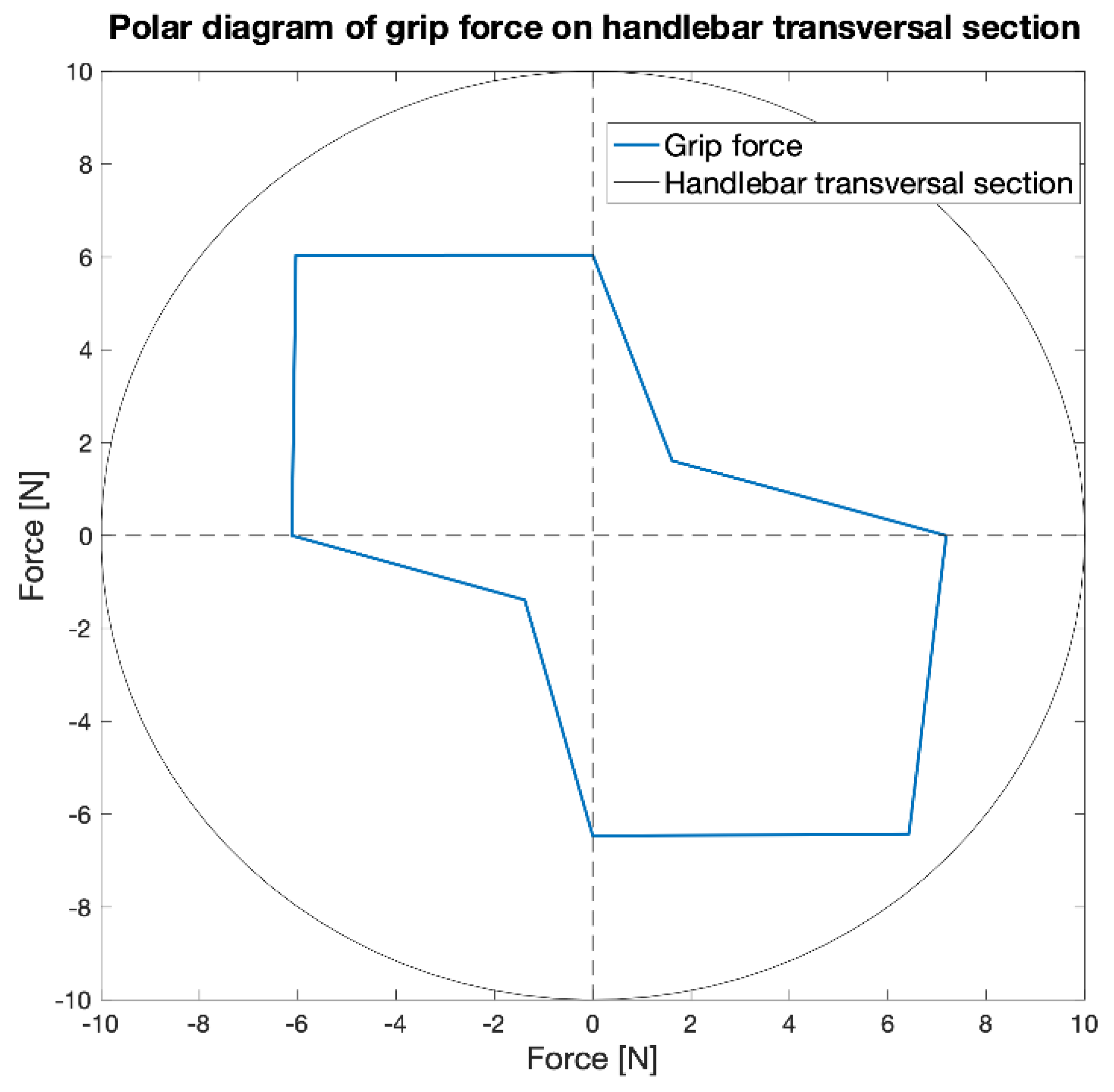
Table 1 shows the mean value of force exerted on the handlebar, the corresponding mean value of current absorbed by the servomotor and the estimated tensile force on the main tendon for all load cell tilts. The mean values were computed by considering ten repetitions of grasp tests and excluding the transients. The measured grip forces vary considerably as the load cell inclination changes: the highest values are reached at 45 degrees and 225 degrees, and the lowest at 135 degrees and 315 degrees. Obviously, higher force is measured when the resultant of the phalanges forces is principally directed along the sensitivity direction of the load cell.
Considering the Table 1 data, the mean current absorption was about 705.62 mA (SD: 46.10 mA) and the mean estimated force exerted on main tendon was 68.49 N (SD: 6.28 N).
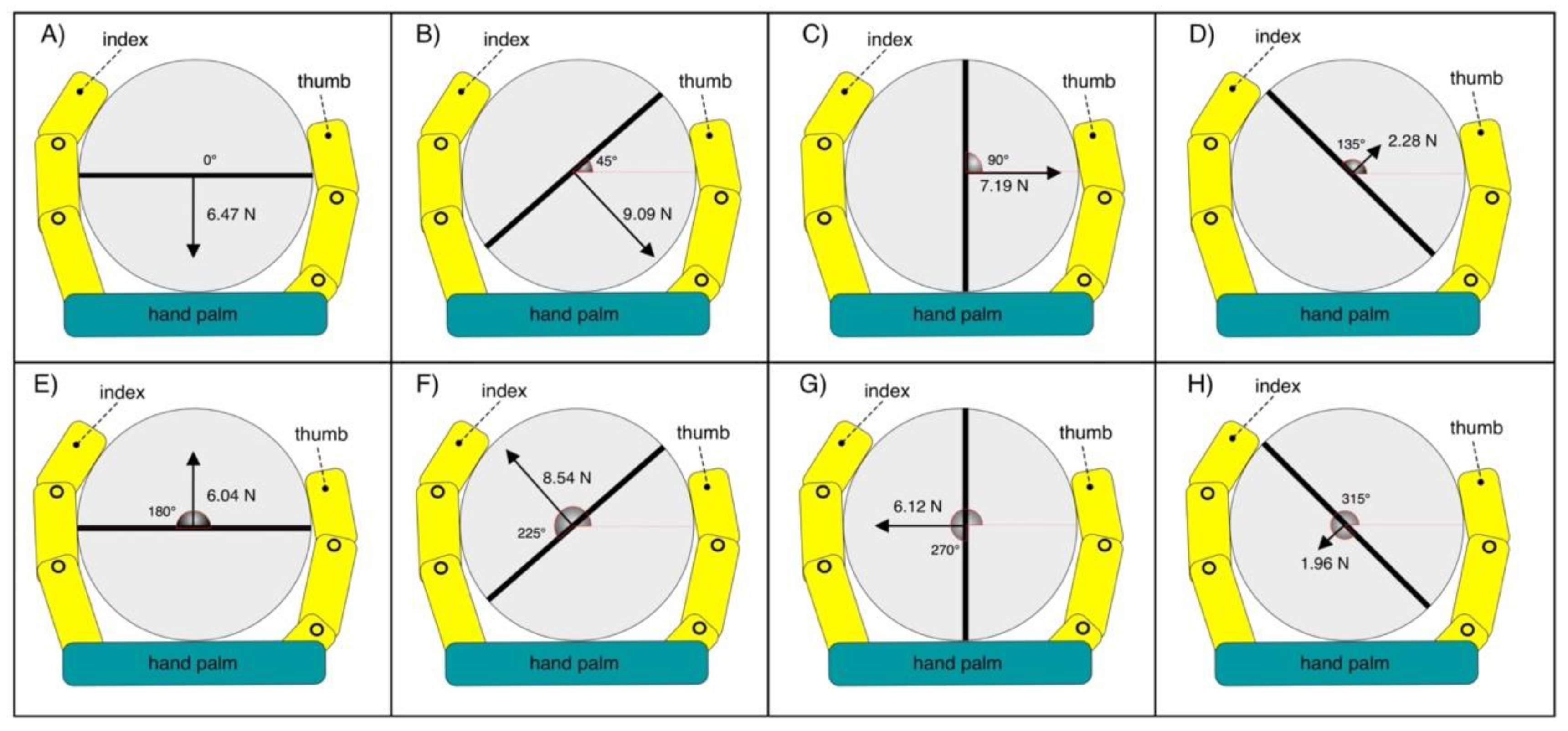
Figure 15 graphically represents the direction and amplitude of the forces measured by the load cell for each handlebar angle.
Figure 16 shows the polar diagram of the force measured by the load cell for the eight angles considered. The direction of maximum force is evident.
Table 2 shows the L2 norm values computed by considering the forces exerted on the load cell in two different positions rotated by 90 degrees. The average value for the load cell position pairs is 8.80 N (SD: 0.74 N) which corresponds to the mean power grip force.
Table 3 outlines the mean force values measured by means of the FSR-based sensors, on each different phalanx that take contact with the handle. On average, the middle phalanges exert the greatest forces.
Finally, the force transfer ratio of the whole mechanical system (see Figure 6), computed as the mean power grip force (8.80 N) divided by the mean force on the main tendon of the prosthesis (68.49 N) was about 12.85%. It was experimentally measured that the loading of the spring present in the mechanical system, for a maximum elongation of about 3 mm, absorbs 7.5 N. The remaining energy is dissipated in friction by the mechanical components of the prosthesis.

3.6. Work for Closing-Opening the Hand and Hysteresis Cycle

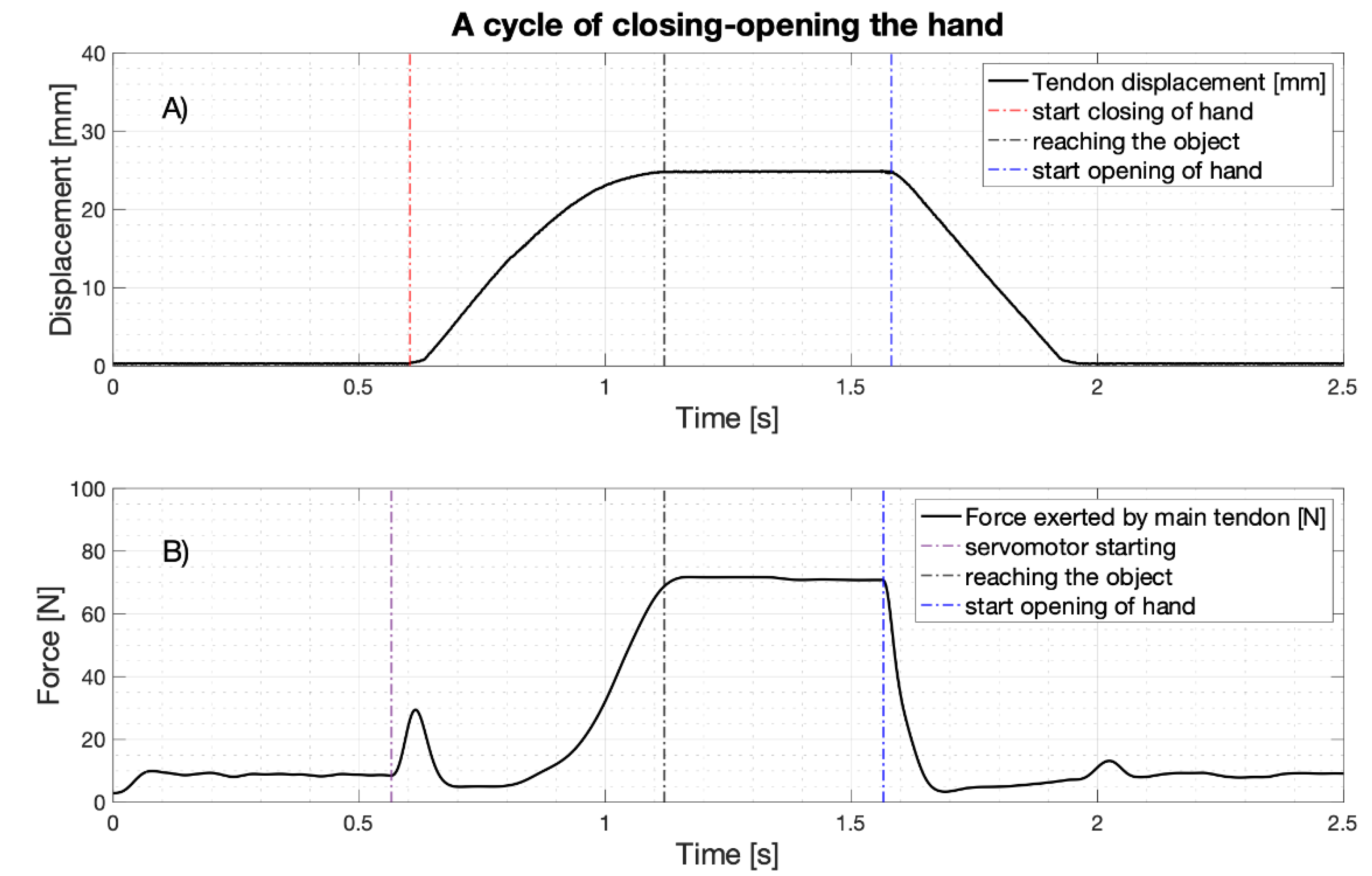
As an example, Figure 17 shows the main tendon displacement and force during a hand grip of the handlebar. Simultaneous recordings (acquired by means of NI USB-6009, with 5 KHz sampling frequency and 14 bit precision) of the main tendon displacement (estimated from the rotary potentiometer), and the force exerted by the same tendon (estimated from the servomotor current, low-pass filtered by a Butterworth 3rd order filter with 10 Hz cut-off frequency) are, respectively, presented in panels (a) and (b). The hand closing-opening cycle consists of a rest phase, a hand closing phase (that ends when the hand grasps the object), a hold-up phase and a release phase. In particular, during the hand closing phase, the tendon excursion increases until reaching the object (at about 25 mm: see panel (a)); likewise, when the hand starts opening, the main tendon gradually returns to its initial position. During rest, there is a pretension of about 9 N on the main tendon (see panel (b)); when the servomotor is triggered, the recorded force presents a pulse of about 30 N, associated to the force necessary to overcome the static frictions of the servomotor and other mechanical parts (note that the tendon is not moving yet). After that, the force quickly returns to the pretension values and then increases reaching its peak value (about 70 N, when the handlebar is firmly grabbed). Finally, when the hand starts opening, the main tendon force rapidly returns to the pretension values.
The relationship between the main tendon force and its displacement is presented in Figure 18. In particular, panel (a) shows a whole cycle of hand closing (blue line) and opening (red line). The blue area under the curve in panel (b) represents the work required for closing the hand (work in); the red area under the curve in panel (c) represents the work returned by the hand during reopening (work out); the magenta area in panel (d) represents the amount of the dissipated energy (hysteresis) for an entire cycle, which is computed as the difference of the two previous works according to the following formula:
Hysteresis   [ Nmm ]   =   Work closing [ Nmm ] Work opening [ Nmm ]  
During consecutive cycles of closing-opening of the hand, the mean values of the works were: work in = 302.17 Nmm (SD: 4.42 Nmm), work out = 196.84 Nmm (SD: 5.91 Nmm), and hysteresis = 106.80 Nmm (SD: 3.31 Nmm).
The energy performances of the “Federica” hand were compared with those of other prostheses available in the literature [26,27] (see Table 4). These other prostheses are body powered and uses anthropomorphic or hook mechanisms. It is evident that prostheses with hook mechanisms have, on average, greater energy efficiency (low hysteresis), with respect to the anthropomorphic prostheses. Nevertheless, “Federica” hand showed the lowest hysteresis among the anthropomorphic prostheses and most of the hook devices considered.

4. Discussion

This study presents the experimental tests carried out on the “Federica” hand, for evaluating its power grip force and energy efficiency. A custom split cylindrical handlebar embedding a single axis load cell was used; it was positioned in various angles during grasp. The mean grip force was 8.80 N (SD: 0.74 N) (average and SD of the L2 norms, according to the NIST guidelines [22]). However, by using more complex measurement systems, such as multi-axis load cells [4,6], that simultaneously sense force contributions from multiple directions, higher values could be obtained.
The current absorption of the single servomotor that actuates all the five prosthetic fingers, was chosen to estimate the force exerted by the main tendon of the prosthesis, during the grasping tasks. This measure of force combined with that of tendon displacement, made it possible to estimate the energy performance of the “Federica” hand, which turned out to be remarkable. It is well known that an efficient mechanism has a low hysteresis [26], that is, low dissipated energy. The “Federica” hand showed a mean hysteresis of 106.80 Nmm, which resulted much lower than most of the considered prostheses [26,27]. Moreover, the energy peak at the servomotor starting (see Figure 17B), when the tendon is still not pulled, involves an overestimation of the hysteresis. The apparently limited force transfer ratio of the mechanical system (about 13%) is typical of the anthropomorphic prostheses, like the “Federica” hand. The actual dimensions of the palm and fingers imply an unfavorable overall lever ratio. As matter of fact, tests carried out on other commercial anthropomorphic prostheses showed a force transfer ratio ranging from 5% to 19% [27] or between 10% and 15% [28]. As expected, hook prostheses showed higher performances because of the different geometry of their articulations, which resulted in force transfer ratios ranging from 30% to 58% [27]. It is worth noting that even the human arm features a low energy efficiency (about 10–15%) [29] because of its natural conformation.
However, thanks to the adaptive grip of the “Federica” hand that is able to wrap around any shaped object [16,17,18,19], a power grip force below 10N, together with a hand closing time of about half a second [18], are enough to support the user in many actions of daily life [7]. The obtained results confirmed that the “Federica” hand with a single servomotor and the differential force distribution mechanism between the fingers, is able to offer high performances that guarantee a secure grip, independent of the shape of the object, and a remarkable grasping speed.

4.1. Limits of the Study

This study has some limitations. A single diameter handlebar was used for the grip test: the forces exerted for the grip of handlebars of different size will presumably be different. The handlebar was equipped with a single axis load cell: more sophisticated load cells systems would allow measuring more parameters simultaneously, including torques. The tensile force on the main actuator tendon was measured indirectly: a direct measurement system will be less prone to errors.

4.2. Future Perspectives

Future studies could be focused on the use of: cylindrical handlebars of different diameters embedding multi axial load cells as in [5], as well as objects of different shapes, such as a sensorized sphere, which would allow testing different grasping configurations, or flat devices for measuring the force exerted by each single finger as in [7]. Other tests can be considered such as traction grip tests, which could be performed e.g., by pulling a handlebar connected to a traction load cell as in [22]. A more accurate evaluation of the force exerted by the main actuator tendon can be achieved by using a tiny traction load cell as in [3].

Author Contributions

Conceptualization, D.E., P.B. and S.S.; methodology and formal analysis, D.E.; investigation, C.C., D.E., E.A., G.D.G. and C.P.; resources, G.C. and G.D.; writing—original draft preparation, D.E.; writing—review and editing, C.C., D.E., E.A., P.B. and S.S.; visualization, D.E.; supervision, P.B. All authors have read and agreed to the published version of the manuscript.

Funding

This research received no external funding.

Institutional Review Board Statement

Not applicable.

Informed Consent Statement

Not applicable.

Data Availability Statement

The data presented in this study are available on request from the corresponding authors.

Conflicts of Interest

The authors declare no conflict of interest.

References

  1. Kurillo, G.; Gregorič, M.; Goljar, N.; Bajd, T. Grip force tracking system for assessment and rehabilitation of hand function. Technol. Health Care Off. J. Eur. Soc. Eng. Med. 2005, 13, 137–149. [Google Scholar] [CrossRef]
  2. Belter, J.T.; Dollar, A.M. Performance characteristics of anthropomorphic prosthetic hands. In Proceedings of the 2011 IEEE International Conference on Rehabilitation Robotics, Zurich, Switzerland, 29 June–1 July 2011; pp. 1–7. [Google Scholar]
  3. Belter, J.T.; Leddy, M.T.; Gemmell, K.D.; Dollar, A.M. Comparative clinical evaluation of the yale multigrasp hand. In Proceedings of the 2016 6th IEEE International Conference on Biomedical Robotics and Biomechatronics (BioRob), Singapore, 26–29 June 2016; pp. 528–535. [Google Scholar]
  4. Weiner, P.; Starke, J.; Hundhausen, F.; Beil, J.; Asfour, T. The KIT prosthetic hand: Design and control. In Proceedings of the 2018 IEEE/RSJ International Conference on Intelligent Robots and Systems (IROS), Madrid, Spain, 1–5 October 2018. [Google Scholar] [CrossRef]
  5. Fu, Q.; Santello, M. Improving fine control of grasping force during hand–object interactions for a soft synergy-inspired myoelectric prosthetic hand. Front. Neurorobot. 2018, 11, 71. [Google Scholar] [CrossRef] [Green Version]
  6. Irwin, C.B.; Towles, J.D.; Radwin, R.G. Development and application of a multi-axis dynamometer for measuring grip force. Ergonomics 2013, 56, 1841–1849. [Google Scholar] [CrossRef] [PubMed] [Green Version]
  7. Szewczyk, R.; Zieliński, C.; Kaliczyńska, M. Automation 2019: Progress in Automation, Robotics and Measurement Techniques; Springer: Berlin/Heidelberg, Germany, 2019; ISBN 978-3-030-13273-6. [Google Scholar]
  8. Measure Grip Forces. Available online: https://www.tekscan.com/measure-grip-forces (accessed on 18 August 2020).
  9. Interlink Electronics Inc. FSR Sensor, Force Sensing Resistor. Available online: https://www.interlinkelectronics.com/force-sensing-resistor (accessed on 13 November 2020).
  10. Carbone, G.; Rossi, C.; Savino, S. Performance comparison between FEDERICA hand and larm hand. Int. J. Adv. Robot. Syst. 2015, 12, 90. [Google Scholar] [CrossRef]
  11. Pylatiuk, C.; Kargov, A.; Schulz, S.; Döderlein, L. Distribution of grip force in three different functional prehension patterns. J. Med. Eng. Technol. 2006, 30, 176–182. [Google Scholar] [CrossRef] [PubMed]
  12. Kargov, A.; Pylatiuk, C.; Martin, J.; Schulz, S.; Döderlein, L. A comparison of the grip force distribution in natural hands and in prosthetic hands. Disabil. Rehabil. 2004, 26, 705–711. [Google Scholar] [CrossRef] [PubMed]
  13. Cosenza, C.; Niola, V.; Savino, S. A mechanical hand for prosthetic applications: Multibody model and contact simulation. Proc. Inst. Mech. Eng. 2018, 232, 819–825. [Google Scholar] [CrossRef] [PubMed]
  14. Carrozza, M.C.; Suppo, C.; Sebastiani, F.; Massa, B.; Vecchi, F.; Lazzarini, R.; Cutkosky, M.R.; Dario, P. The SPRING hand: Development of a self-adaptive prosthesis for restoring natural grasping. Auton. Robot. 2004, 16, 125–141. [Google Scholar] [CrossRef]
  15. Kamikawa, Y.; Maeno, T. Underactuated five-finger prosthetic hand inspired by grasping force distribution of humans. In Proceedings of the 2008 IEEE/RSJ International Conference on Intelligent Robots and Systems, IROS, Nice, France, 22–26 September 2008; pp. 717–722. [Google Scholar]
  16. Bifulco, P.; Esposito, D.; Gargiulo, G.D.; Savino, S.; Niola, V.; Iuppariello, L.; Cesarelli, M. A stretchable, conductive rubber sensor to detect muscle contraction for prosthetic hand control. In Proceedings of the 2017 E-Health and Bioengineering Conference (EHB), Sinaia, Romania, 22–24 June 2017; pp. 173–176. [Google Scholar]
  17. Esposito, D.; Cosenza, C.; Gargiulo, G.D.; Andreozzi, E.; Niola, V.; Fratini, A.; D’Addio, G.; Bifulco, P. Experimental study to improve “Federica” prosthetic hand and its control system. In Proceedings of the XV Mediterranean Conference on Medical and Biological Engineering and Computing—MEDICON 2019, Coimbra, Portugal, 26–28 September 2019; Henriques, J., Neves, N., de Carvalho, P., Eds.; Springer International Publishing: Coimbra, Portugal, 2020; pp. 586–593. [Google Scholar]
  18. Esposito, D.; Savino, S.; Cosenza, C.; Gargiulo, G.D.; Fratini, A.; Cesarelli, G.; Bifulco, P. Study on the activation speed and the energy consumption of “Federica” prosthetic hand. In Proceedings of the XV Mediterranean Conference on Medical and Biological Engineering and Computing—MEDICON 2019, Coimbra, Portugal, 26–28 September 2019; Henriques, J., Neves, N., de Carvalho, P., Eds.; Springer International Publishing: Coimbra, Portugal, 2020; pp. 594–603. [Google Scholar]
  19. Federica Prosthetic Hand. Available online: http://ingegneria-biomedica.dieti.unina.it/index.php/en/projects/federica-prosthetic-hand.html (accessed on 18 August 2020).
  20. Esposito, D.; Andreozzi, E.; Fratini, A.; Gargiulo, G.D.; Savino, S.; Niola, V.; Bifulco, P. A piezoresistive sensor to measure muscle contraction and mechanomyography. Sensors 2018, 18, 2553. [Google Scholar] [CrossRef] [PubMed] [Green Version]
  21. Esposito, D.; Andreozzi, E.; Gargiulo, G.D.; Fratini, A.; D’Addio, G.; Naik, G.R.; Bifulco, P. A piezoresistive array armband with reduced number of sensors for hand gesture recognition. Front. Neurorobot. 2020, 13, 114. [Google Scholar] [CrossRef] [PubMed] [Green Version]
  22. Falco, J.; Van Wyk, K.; Messina, E. Performance Metrics and Test Methods for Robotic Hands. NIST Tech. Rep. DRAFT NIST 2018, 1227. [Google Scholar] [CrossRef]
  23. INA122 Data Sheet, Product Information and Support|TI.Com. Available online: https://www.ti.com/product/INA122 (accessed on 20 August 2020).
  24. Hitec HITEC Robot Servo. Available online: https://hitecrcd.com/products/servos/discontinued-servos-servo-accessories/hsr-5990tg-hmi-ultra-premium-robot-servo/product (accessed on 20 August 2020).
  25. Industries, A. INA169 Analog DC Current Sensor Breakout—60V 5A Max. Available online: https://www.adafruit.com/product/1164 (accessed on 20 August 2020).
  26. Smit, G.; Bongers, R.M.; Van der Sluis, C.K.; Plettenburg, D.H. Efficiency of voluntary opening hand and hook prosthetic devices: 24 years of development? J. Rehabil. Res. Dev. 2012, 49, 523–534. [Google Scholar] [CrossRef] [PubMed] [Green Version]
  27. Smit, G.; Plettenburg, D.H. Efficiency of voluntary closing hand and hook prostheses. Prosthet. Orthot. Int. 2010, 34, 411–427. [Google Scholar] [CrossRef] [PubMed] [Green Version]
  28. De Visser, H.; Herder, J.L. Force-Directed design of a voluntary closing hand prosthesis. J. Rehabil. Res. Dev. 2000, 37, 261–271. [Google Scholar] [PubMed]
  29. Hagler, S. Patterns of Selection of Human Movements IV: Energy Efficiency, Mechanical Advantage, and Asynchronous Arm-Cranking. arXiv 2018, arXiv:1702.03271. [Google Scholar]
Figure 1. 3D printed handlebar for the load cell: (A) transversal view; (B) lateral view; (C) rendering of the exploded components in lateral view.
Machines 09 00025 g001
Figure 2. Load cell conditioning circuit based on instrumentation amplifier (INA122).
Machines 09 00025 g002
Figure 3. Force measure system for mapping the grip forces distribution between the phalanges: (A) Illustration from a lateral view of the “Federica” hand while grasping the cylindrical handlebar; (B) Illustration of the FSR-based sensors placements on the selected phalanges; (C) Conditioning circuit (current mirror) for one of the FSR-based sensors.
Machines 09 00025 g003
Figure 4. The “Federica” hand: (A) Palm side exposed; (B) Force distribution in the differential mechanical system, made of pulleys and inelastic tendons.
Machines 09 00025 g004
Figure 5. “Federica” hand while grasping the cylindrical handlebar during the performed grip tests
Machines 09 00025 g005
Figure 6. Diagram illustrating the flow of the force generated by the servomotor of the “Federica” hand.
Machines 09 00025 g006
Figure 7. Current measurement circuit based on INA169. VIN = 7.4 V; RSHUNT = 0.1 Ω; RL = 9.35 KΩ; RG1 = RG2 = 1 KΩ.
Machines 09 00025 g007
Figure 8. Servomotor configurations: (A) Calibration test; (B) Implementation in the prothesis.
Machines 09 00025 g008
Figure 9. Experimental test of power grip force measurement, with the handlebar in eight different position with respect to the prosthesis palm: (A) 0 degrees; (B) 45 degrees; (C) 90 degrees; (D) 135 degrees; (E) 180 degrees; (F) 225 degrees; (G) 270 degrees; (H) 315 degrees. The red arrow represents the load cell sensing axis.
Machines 09 00025 g009
Figure 10. Load cell static calibration: scatter plot of the experimental data (o) and linear regression (continuous red line).
Machines 09 00025 g010
Figure 11. Static calibration of an FSR-based sensor used to measure phalanx contact force: scatter plot of the experimental data (black circles) and the regression line (red line).
Machines 09 00025 g011
Figure 12. Relationship between the current absorbed by the servomotor (scaled in mA) and the torque generated (scaled in Ncm). The 2nd order polynomial regression function is depicted as red continuous line.
Machines 09 00025 g012
Figure 13. Relationship between the output voltages [V] from the rotary potentiometer fixed to the servomotor shaft as a function of the main actuator tendon displacement [mm]. Experimental data are plotted as black circles, while the linear regression function is plotted as a red continuous line.
Machines 09 00025 g013
Figure 14. Example of experimental data recorded during the power grip test (here handlebar tilted 45 degrees): (A) Absorbed current by the servomotor; (B) Grip force on the handlebar (load cell output).
Machines 09 00025 g014
Figure 15. Measured force represented as vectors, for each tilt of the handlebar: (A) 0 degrees; (B) 45 degrees; (C) 90 degrees; (D) 135 degrees; (E) 180 degrees; (F) 225 degrees; (G) 270 degrees; (H) 315 degrees.
Machines 09 00025 g015
Figure 16. Polar diagram of the force measured by the load cell for the eight angles considered.
Machines 09 00025 g016
Figure 17. A cycle of closing-opening the hand: (A) main tendon displacement (estimated from the rotary potentiometer) [mm]; (B) force exerted by the main tendon (estimated from the current absorption of the servomotor) [N].
Machines 09 00025 g017
Figure 18. Main tendon force–displacement relationship (A) A whole cycle of hand closing (blue line) and opening (red line), the arrows indicate the direction of travel; (B) The blue area is the work required for closing the hand (work in); (C) The red area is the work returned by the hand during reopening (work out); (D) The magenta area is the dissipated energy per cycle.
Machines 09 00025 g018
Table 1. Experimental data of the grip tests. For each angular position of the handlebar: the mean value of force exerted on the load cell in the handlebar, the mean value of current absorbed by the servomotor and the estimated force exerted on the main tendon of prosthesis.
Load Cell Tilt
[Degrees]
Mean Force Exerted on the Load Cell [N]Mean Current Absorbed by the Servomotor [mA]Estimated Tensile Force Exerted on the Main Tendon of the Prosthesis [N]
06.4775875.64
459.0970267.81
907.1968565.50
1352.2862858.22
1806.0471269.25
2258.5477177.67
2706.1271870.09
3151.9667163.72
Table 2. L2 norm values for pairs of load cell positions rotated by 90 degrees.
Load Cell Positions [Degrees]L2 Norm of Exerted Forces on the Handlebar [N]
0 and 909.67
45 and 1359.37
90 and 1807.54
135 and 2258.84
180 and 2708.60
225 and 3158.76
Table 3. Mean forces [N] on the selected phalanxes of the prosthesis measured by means of the FSR-based sensors.
FingerPhalanxMean Force
on FSR-Based Sensor [N]
ThumbDistal1.89
IndexDistal1.95
Medial2.38
MiddleDistal2.45
Medial4.61
RingDistal0.91
Medial2.39
LittleDistal1.09
Medial1.21
Table 4. Works for hand opening, closing and hysteresis [Nmm] of different hand prostheses. The acronym VO stands for voluntarily open, while VC stands for voluntarily closed. The hook prostheses are highlighted with a grey background.
ProsthesisWork for Hand Closing [Nmm] (Mean Value ± SD)Work for Hand opening [Nmm] (Mean Value ± SD)Hysteresis [Nmm]
(Mean Value ± SD)
Federica Hand302.17 ± 4.42196.84 ± 5.91 106.80 ± 3.31
Hosmer APRL VC Hand 525411058 ± 4-298 ± 8
Hosmer APRL VC Hook 52601720 ± 6-138 ± 3
Hosmer Soft VC hand 61794 2292 ± 12-1409 ± 37
TSR VC Hook -Grip 2SS284 ± 3-52 ± 1
Otto Bock VC 8K24, frame1624 ± 8-389 ± 19
Hosmer Sierra VO Hand (ungloved)-1152 ± 8637 ± 6
RSL Steeper VO Hand (ungloved)-1758 ± 27855 ± 6
Otto Bock VO Hand (ungloved)-2545 ± 11917 ± 5
Hosmer Becker VO (ungloved)-2748 ± 171710 ± 9
Hosmer Model VO 5XA Hook (1 band)-1128 ± 14290 ± 3
Otto Bock VO 10A60 Hook -1002 ± 3482 ± 5
Hosmer Sierra 2 Load VO Hook -1243 ± 11379 ± 1
RSL Steeper Carbon VO-1619 ± 2487 ± 4
Publisher’s Note: MDPI stays neutral with regard to jurisdictional claims in published maps and institutional affiliations.