1. Introduction
Till now, different types of robotic hands have been developed for the purpose of grasping and manipulating daily objects. Among them, anthropomorphic hands were developed to mimic the dexterity of the human hand. Well-known designs include the Utah-MIT Hand [
1], the DLR Hand [
2], the Shadow Hand [
3], and the Robonaut 2 Hand [
4]. Most of these dexterous robotic hands are complicated in either mechanical structure or control architecture. In general, their maintenance is complicated and their manufacturing costs are high. Hence, most of them are only applied to the research community and are still far from practical applications, as reported in [
5]. Thus, a lot of effort has been put into the design of low-cost, simple-maintenance, and easy-operation robotic hands which could be widely applied to practical applications such as the automation industry and medical rehabilitation. To this end, particular attention has been paid to designing non-anthropomorphic robotic hands/grippers with an underactuated structures which could reduce the number of actuators and require simple control systems for a given task [
6,
7,
8,
9]. Compared with fully actuated robotic hands, underactuated robotic hands reduce the number of actuators while relatively preserving the ability of dexterous grasping [
10]. Moreover, underactuation design also provides safety and robustness against environmental uncertainties during grasping [
11,
12].
Based on mechanical elements used in the power transmission system, underactuated robotic hands/grippers can be classified into three main types as follows: the wire-driven type [
13,
14,
15,
16,
17,
18,
19,
20,
21,
22], the linkage-driven type [
23,
24,
25,
26,
27,
28,
29,
30,
31,
32,
33,
34], the gear-driven type [
35,
36,
37,
38,
39], and some combinations [
40,
41,
42]. The wire-driven type has advantages of compact size, light weight, and good shape-adaptive properties when encompassing the object to be grasped. However, it has disadvantages such as wire slack, complicated maintenance, and a small grasping force that is constrained by the cable strength and pretension force. Comparatively, the linkage-driven type has the advantage of high safety because the rigid linkages can be used to transmit large force. However, due to the link interference, its workspace, in general, is smaller than that of the wire-driven or gear-driven type. Moreover, for a multi-degree-of-freedom (DOF) linkage-driven finger mechanism, it is difficult to mount all of the actuators on the base (palm).
In general, elastic elements such as springs and compliant joints are required and combined with mechanical stoppers for the purpose of avoiding undesired motion and achieving multiple grasp modes stably. To prevent undesired motion during underactuated grasping, elastic elements (springs and compliant joints) and mechanical stoppers generally are required to provide passive control. These passive elements are also referred to as “passive actuators”. During the open-close motion of the finger, the stiffness of the spring should be large enough to prevent undesired motion due to gravity and inertia terms. Once contact with an object is established at the proximal phalanx, the actuator has to increase the actuation torque (to withstand preloading and deformation of the spring) to continue the close motion until a static equilibrium is achieved. This variation is generally significant. For a certain range of input torque and object sizes, a balance of design stiffness and preloading of the torsion spring should be considered to maximize the stable power-grasping region [
43]. In our previous study [
27], a functional robotic finger prototype was designed intuitively without investigating the grasping behavior of the final design. The development of this finger prototype is primarily based on a specific CAD-aided simulation and lacks a systematic framework for its designing and analysis. For bin-picking applications, a gripper that combines vacuum suction grasping [
44] and two independently controlled mechanical fingers has been built using a similar approach, i.e., intuitive design based on a specific CAD-aided simulation. In this paper, the authors tried to provide an approach that combines the dynamics and statics of the underactuated robotic finger to select the appropriate stiffness and preloading of the spring.
In this paper, we present the design issues and applications of a 3-DOF underactuated robotic finger. Architecture description and grasping modes analysis are presented in
Section 1.
Section 3 presents the dynamic modeling of this robotic finger and an approach to selecting the torsional spring. In
Section 4, static modeling of this finger mechanism is presented. In
Section 5, a two-fingered underactuated robotic gripper is developed. Finally, multiple grasping modes of this robotic finger are verified experimentally.
2. Architecture of the Robotic Finger Mechanism
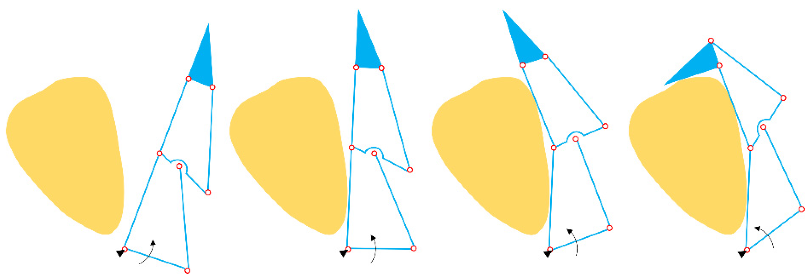
The grasping sequence of a general three-phalanx underactuated robotic finger is shown in
Figure 1. By adding passive elements (springs and mechanical stoppers) at the pivot joint between adjacent phalanxes and activating the lower link (indicated by the arrow), the proximal, intermediate, and distal phalanx will make a contact with the object in sequence once the lower link (indicated by the arrow) is actuated. This finger can only be used to perform shape-adaptive grasping. However, in a real-world scenario, users expect the robotic finger to perform multiple grasping tasks such as parallel grasping and shape-adaptive grasping. In this case, special design architecture is required. The well-known three-phalanx adaptive gripper from the Robotiq company (licensed from [
45]) is developed by modifying the robotic finger shown in
Figure 1.
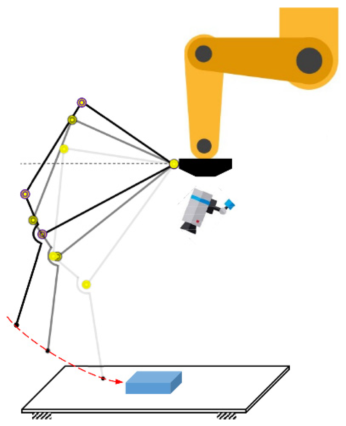
The motivation of this research is to develop a new robotic gripper for grasping a wide range of household objects. According to this grasping scenario, the robotic gripper is expected to provide the following functions: fingertip parallel grasping; shape-adaptive grasping; and the ability to stably grasp objects with low heights, such as a coin, pill, pen, toothbrush, phone, etc., lying on a flat surface. Except for the simple parallel-jaw gripper, most of the other grippers are rotational grippers, i.e., the whole finger open-close motion is controlled by a rotational joint as illustrated in
Figure 2, from which we can find that the trajectory of the fingertip point is an arc (swing trajectory indicated by red dashed line). Obviously, the vertical distance from the fingertip to the palm (usually fixed to the end-effector of an industrial robot) will be changed during the grasping. If the industrial robot is fixed during this process, the vertical distance from the fingertip to the supporting surface also keeps changing. In this case, the industrial robot generally has to be controlled by using certain robot-vison algorithms to adjust the position of the fingertip in order to make contact with the object to be grasped. For those objects with low heights, a good calibration algorithm and a highly accurate robot-vision system are generally required for avoiding making contact with the supporting surface. As visual localization errors always exist, coordinate control errors of industrial robot and robotic gripper, and uncertainties of the grasping environment, the fingertip makes contact with the environment frequently while grasping household objects that have varied shapes and sizes. For many of the previous underactuated grippers, the fingertips are passively coupled with other phalanxes and the directions of the fingertips will be changed passively and become not parallel to each other while making contact with the supporting surface. Such non-parallel fingertips may cause unstable contact-based pinching grasping. A stable contact-based pinching grasping requires that the fingertip is not passively coupled with other phalanxes, i.e., after contact with the supporting surface, the direction of the fingertip will not be changed passively. This design concept is shown in
Figure 3.
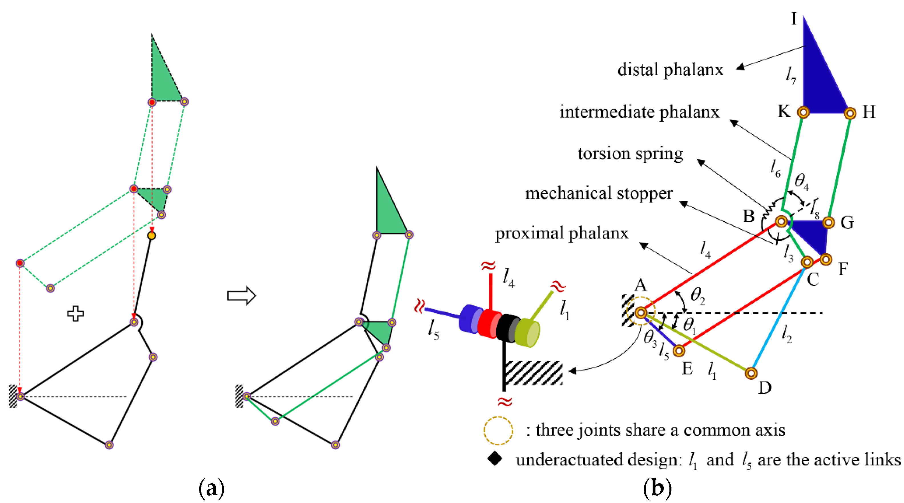
Based on the above analysis, a three-phalanx linkage-driven robotic finger is proposed as shown in
Figure 4a. The proposed finger mechanism was constructed by stacking one four-bar mechanism (underactuated 2-DOF finger) over one double parallelogram mechanism. Referring to
Figure 4b, this finger has three DOFs, which can be fully controlled by activating the three independent links (
,
, and
). It is noted that the three independent links are pivoted at the same joint axis and that all the actuators can be mounted on the base. In this work, we focus on the underactuated design that can be achieved by only activating the links
and
as shown in
Figure 4b. The link
is designed as a passive link to adapt to different shapes of objects. One torsion spring is used to prevent the counterclockwise rotation (caused by gravity and inertia effects) between the proximal and intermediate phalanxes. One mechanical stopper is used to prevent hyperextension rotation in the clockwise direction. Moreover, ball bearings are placed at each joint to reduce friction and backlash. It is noted that the link
is used to control the orientation of the distal phalanx independently. Independent fingertip control not only provides stable contact-based grasping, but also reduces the control complexity in other grasping tasks.
A comparison of the Robotiq three-phalanx gripper (licensed from Sarah hand [
45]) is shown in
Figure 5. We can find that both of these two grippers can achieve parallel precision and power grasping. We note that even though these two finger mechanisms have similar appearances, a detailed investigation revealed that their mechanical structures and working principles are completely different from each other and our proposed finger mechanism has a simpler architecture. For the proposed finger mechanism shown in
Figure 5a–c, the direction of its fingertip is decoupled from the movements of the proximal and intermediate phalanxes. To perform some challenging grasping tasks, the fingertip is designed to be actively controlled. The Sarah finger mechanism shown in
Figure 5d–f was constructed by stacking one double parallelogram over a general three-phalanx adaptive finger that consists of two four-bar mechanisms. Mechanical stoppers and springs are installed at both the top and bottom ends of the finger. The clever idea behind Sarah finger is that the intermediate phalanx is passively coupled with the proximal phalanx and the fingertip (the distal phalanx) is passively coupled with the intermediate phalanx.
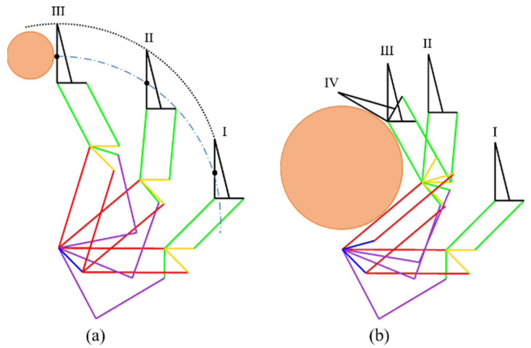
As shown in
Figure 6, both parallel and shape-adaptive grasping can be achieved by using this underactuated finger mechanism. Through activating the link
shown in
Figure 4b, the parallel grasping can be achieved if no external contact occurs at the proximal phalanx. A torsion spring and mechanical stopper are used to provide passive control so that the proximal and intermediate phalanxes can move together as shown in
Figure 6a. If the proximal phalanx makes physical contact with the object firstly during activating the link
, the shape-adaptive grasping will start as shown in
Figure 6b. In this case, the intermediate phalanx continues to move, and the actuator has to increase the torque significantly to withstand the twisting of the torsion spring. From phase III to phase IV, the orientation of the distal phalanx is adjusted to provide one more contact with the object by activating the link
.
3. Dynamic Modeling of the Robotic Finger
The dynamic model provides the relationship between the input actuation torque and output motion of the robotic finger, and thus it is important for the design and control of a robotic finger systematically. For example, in a piece-picking challenge, the users might expect high-speed open-close motion of a gripper. For a target open-close speed, the dynamic model can be used to evaluate how much torque the actuator should provide to generate such a high-speed open-close motion. Then the appropriate actuator size can be determined and vice versa. As far as our underactuated finger is considered, a torsion spring is used to provide passive control. For the parallel grasping shown in
Figure 3, preloading of the torsion spring should be large enough to prevent counterclockwise rotation (between the proximal and intermediate phalanxes) due to gravity and inertia effects. In this paper, the authors attempted to analytically investigate how much preloading the spring should be designed with. The dynamics and statics of this robotic finger are combined to provide guidance for selecting appropriate torsion springs.
3.1. Dynamic Model
For the underactuated design shown in
Figure 4b, the joint
and
are selected as the active joints while the joint
is a passive joint. A torsion spring and a mechanical stopper, instead, are mounted on the joint
to provide passive control. As discussed above, the preloading of the torsion spring should be bigger than the negative (clockwise direction) torque required at the joint
for stable parallel grasping. To determine how much preloading of the torsion spring should be designed, we assume that the joint
is a virtual active joint and there exists no torsion spring or mechanical stopper installed at this joint. Hence, we select the joints
,
, and
as the three independent joint variables to build the finger dynamic model.
The Lagrangian of this robotic finger is defined as
where
denotes the kinetic energy and
denotes the potential energy.
The kinetic energy can be found as
where
,
Here,
and
represent the rotation matrix and inertia matrix of link
, respectively.
and
represent the linear and angular velocity Jacobians of link
, respectively. They can be described as
where
,
, and
represents a unit vector along the direction of the joint
in a serial open chain used for calculating the linear and angular velocity Jacobians of link
.
The potential energy can be written as
where
is the gravitational vector and
is the position vector of the mass center of the link
. The equations of motion for this robotic finger can be found as
For the parallel grasping, the joint
keeps being constant. Thus, we have
Once a joint trajectory is defined (, , and are knowns) for the parallel grasping, the actuation torque required at the joint can be obtained by using Equation (6). However, in areal situation, joint is a passive joint and its motion is passively controlled by the torsion spring and mechanical stopper. It is noted that the mechanical stopper is used to constrain the relative rotation (between the proximal and intermediate phalanxes) in the clockwise direction while the torsion spring is used to constrain the relative rotation in the counterclockwise direction. To make sure that the joint angle is constant during parallel grasping, the preloading of the torsional spring should be bigger than the torque required in the clockwise direction. The stopper provides a rigid constraint in the clockwise direction. Thus, any motion trend in the clockwise direction is prohibited by the stopper. Comparatively, any motion in the counterclockwise direction is allowed, but constrained by the torsion spring.
3.2. Dynamic Simulations and Selection of the Torsion Spring
In order to precisely select a torsion spring for a target grasping application, we need to consider different velocities, accelerations, and decelerations during dynamic simulations. However, we cannot take all the real scenarios into consideration actually. Instead, we could approximately evaluate the minimum preloading of the torsion spring and provide dynamic guidance to select the torsion spring by considering several bad-case scenarios. An exemplary joint trajectory is defined as
where
. Additionally, for the joint
, two fifth-order polynomials are used during
and
, respectively. This trajectory implies that the finger finished closing or opening of 70 degrees (almost from the fully opened to closed) in two seconds, which is fast enough for our application.
We performed the dynamic simulations in MATLAB and verified the analytical model in a commercialized multi-body dynamic simulator called “DAFUL”, which has now been sold and merged into the ANSYS environment with a new name called “ANSYS Motion” [
46]. The MATLAB simulation result is shown in
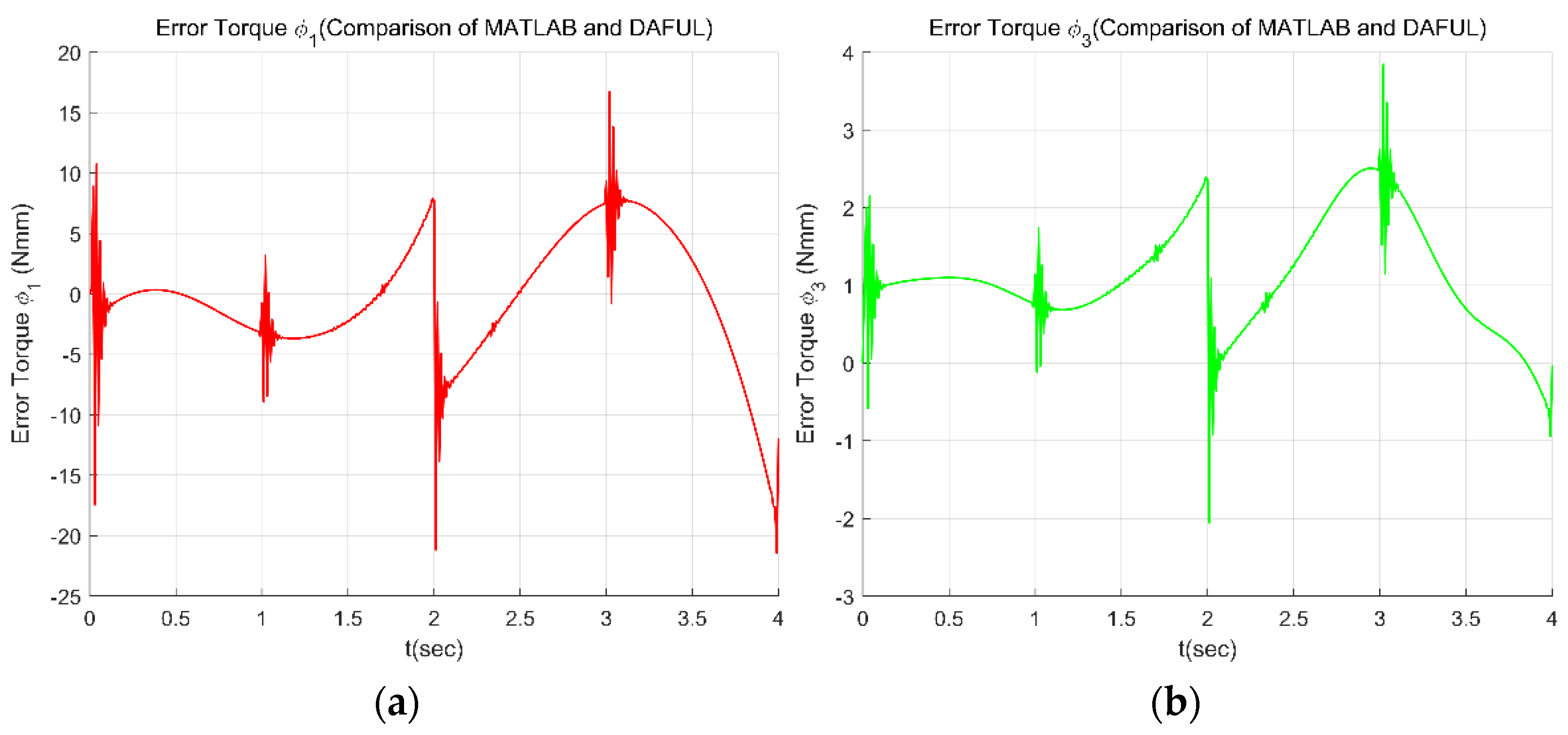
Figure 7. A comparison with the DAFUL simulation result is shown in
Figure 8. Referring to
Figure 8, we can find that the difference between our analytical dynamic model and the multi-body dynamic simulation result is quite small (the very small difference might come from the non-perfect dynamic parameters that we got from the 3D software). From
Figure 7c, we can find the negative (clockwise direction) torque required at the joint
during the trajectory. In a real situation, this torque should be provided by the torsion spring to ensure that the parallel grasping is stable. Hence, the preloading of the torsion spring should be bigger than the maximum torque (around −40 Nmm) required in the clockwise direction.
To verify the above-mentioned hypothesis, we have performed another DAFUL simulation where the joint
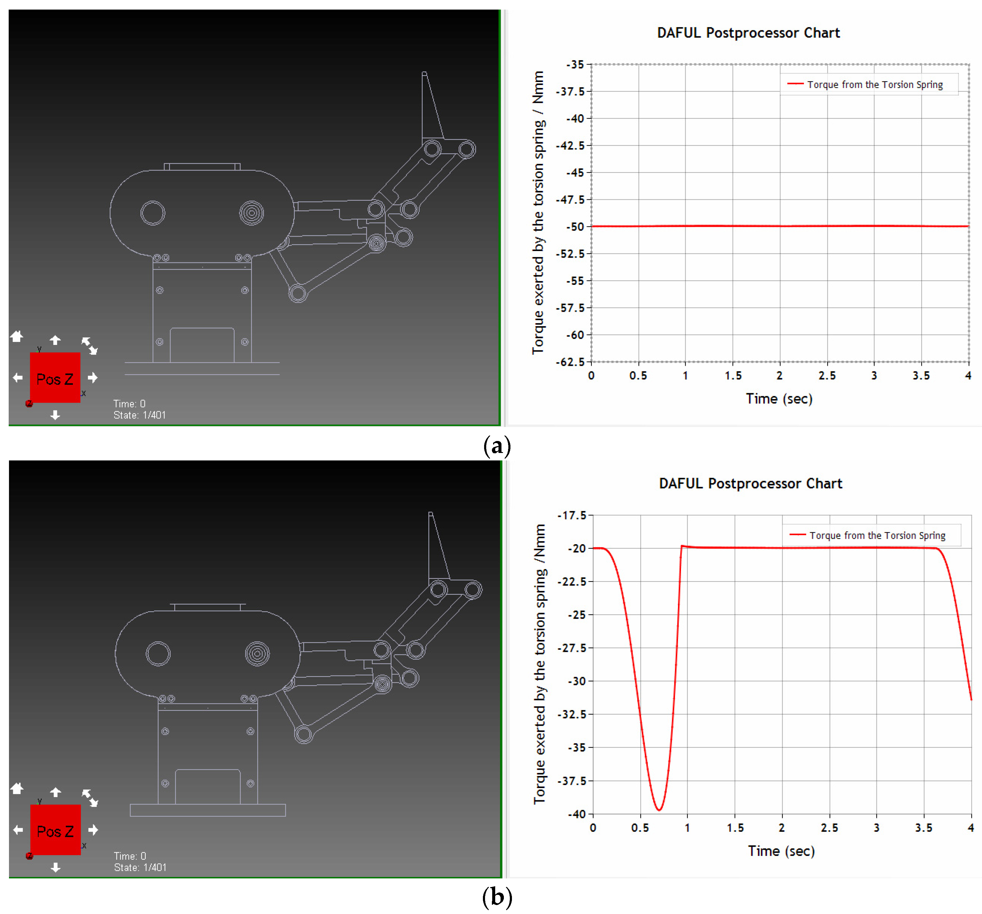
is defined as a passive joint and the torsion spring and mechanical stopper are added instead. Two different preloadings (50 Nmm and 20 Nmm) of the torsion spring have been tested in the DAFUL simulation. Variations of the resistance torque of the torsion spring with preloadings of 50 Nmm and 20 Nmm during the trajectory are shown in
Figure 9a,b, respectively. In each subfigure, the left panel shows the initial and final state of the finger in the dynamic simulator, whilethe right panel shows the variation of the torque exerted by the torsion spring during the dynamic simulation. From
Figure 9a, we can find that the torque of the torsion spring keeps being constant (the same as the preloading of 50 Nmm), which implies that the joint
keeps being constant, and there exists no passive motion between the proximal and intermediate phalanxes during the trajectory. On the other hand, it can be found from
Figure 9b that the torque of the torsion spring varies due to inertia and gravity effects. This implies that the joint
has a small undesired variation that may cause unstable parallel grasping. Other joint trajectories with higher joint acceleration or deceleration could be performed in MATLAB. Ultimately, by investigating the maximum torque that appeared in the clockwise direction and considering a certain safety threshold, an appropriate torsion spring can be selected. It is noted that the approach presented here can be generalized and applied to design other underactuated robotic hands.
4. Static Grasp Model
The quasi-static grasp model provides the relationship between the input actuation torque and the contact forces exerted on the object. Expanded details of the following derivation can be found in
Appendix A and
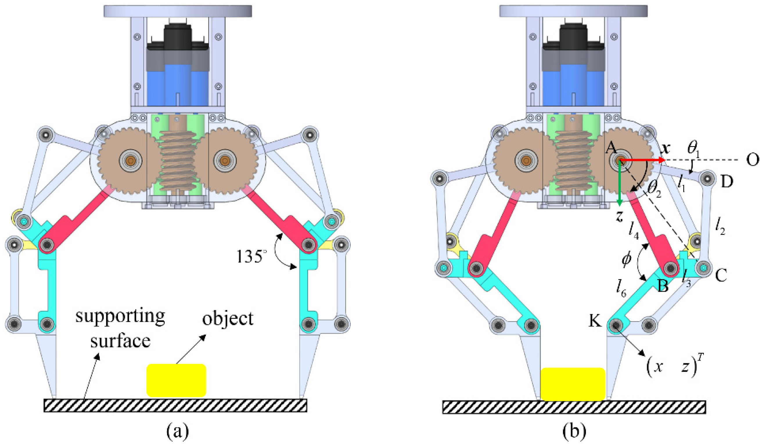
Appendix B. The four-bar linkages ABCD shown in
Figure 4b have two DOFs, from which all the joint angles of the linkages can be determined. We write the closed-loop kinematic equations and express the matrix
, which relates dependent joint variables to independent joint variables. For our model, those variables are defined as
By considering the different number of contact points, two types of static grasp models are developed, respectively.
4.1. Two-Point Contact Model
By activating the joint
at link AD, a shape-adaptive two-point contact can happen as shown in
Figure 10a. Expanded details of the following derivation of this section can be found in
Appendix A. Through analyzing the four-bar linkages ABCD, we define the matrix
that relates dependent joint
to
, and the matrix
that relates the actuated joint angle
to
, such that
Then we define two matrices
and
that relate the motion of the two contact points,
and
, to
, such that
In order to obtain the simple and general results that can characterize the finger itself, only the normal force at the contact point is considered. Obviously, the omitted local properties such as friction coefficients at the contact surface can have an impact on the grasp stability but exceed the scope of this paper. Our primary goal is to investigate the capability of the robotic finger (and only the finger) to exert a wrench onto a fixed object. We are, therefore, not interested in the local properties of the contact, such as friction or geometry of the contact. By defining a selection matrix,
, we can reformulate the Jacobian of
in Equation (13) to remove tangential components, and the final result is given as
By using the virtual work principle, the static equilibrium of the two-point contact can be achieved if the following effective torque relationship with respect to the independent input holds
where
is the actuation torque, and
is the vector composed of normal contact forces at proximal and intermediate phalanxes.
is the twisted torque of the torsion spring;
denoted the preloading of the torsion spring before the adaptive grasping happens, and the constant value
is assumed to be the same as the initial angle of
that is designed as 135° here.
Finally, the two contact forces,
and
, can be solved as
where
.
4.2. Three-Point Contact Model
As shown in
Figure 10b, the distal phalanx of this robotic finger can be independently controlled by the active joint
to add one more contact with the object. Expanded details of the following derivation of this section can be found in
Appendix B. In this model, the independent joint variables are defined as
Firstly, the active joints
and
can be expressed as
where
,
.
Similar to the two-point contact model, the motion of the three contact points can be obtained as
By defining a selection matrix,
, we can take the normal components of the motion at the three contact points as
By using the virtual work principle, the conditions for static equilibrium of the three-point contact can be obtained as
Finally, the three contact forces,
,
, and
, can be obtained as
where
.
4.3. Simulation of the Grasping Motion
A cylindrical object is used as a typical example in developing the contact model. As far as the configuration of the object is given, the configuration of the robotic finger can be completely defined by considering the contact constraints shown in
Figure 10. Then the normal contact forces can be calculated for a given object and actuation torque. A shape-adaptive two-point contact shown in
Figure 10a is selected as an example to investigate the relationship among the contact forces, the stiffness and preloading of the torsion spring, and the actuation torque. In
Figure 10, the reference coordinate is located at the point
;
and
denote the coordinates of the center of the circle.
Firstly, given the position of the center (denoted by
) of the cylindrical object, the angle
can be found as
where
,
.
Then the angle
can be found as
where
.
Finally, by analyzing the four-bar linkage ABCD, we can obtain the angle , and the contact forces can be found by using Equation (16).
For shape-adaptive grasping, stiffness and preloading of the torsion spring are useful for holding the object. During the grasping process toward the static equilibrium, the second contact will be retained with the intermediate phalanx by sliding against the object. If the preloading and stiffness of the torsion spring are too low, closing ejection might happen, which implies that the proximal phalanx will lose contact with the object. For one example of the input torque
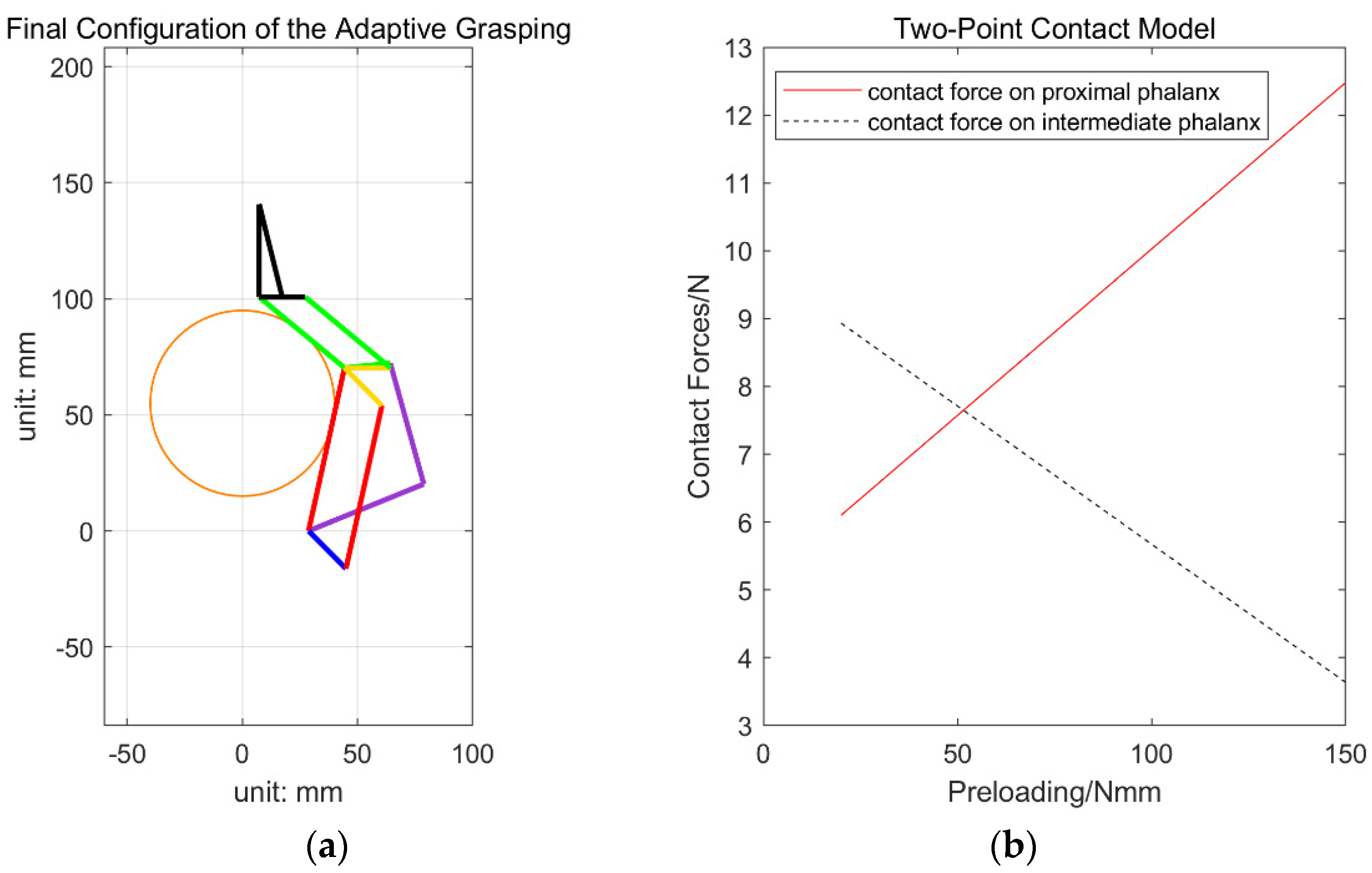
, the relationship between the two contact forces exerted on the proximal and intermediate phalanxes and the preloading of the torsion spring is shown in
Figure 11b. It is noted that the spring stiffness used in this simulation is 3 Nmm/deg. It can be found that after increasing the preloading of the spring, the contact force at the proximal phalanx will increase while the contact force at the intermediate phalanx will decrease. For a stable two-point contact grasp, both of the two contact forces exerted on the proximal and intermediate phalanxes should be positive to avoid losing contact with the object. For a certain range of input torque and object sizes, a balance of design stiffness and preloading of the torsion spring should be considered to maximize the stable grasping region. We note that the crossing point of red and black lines shown in
Figure 11b is not directly used to decide the stable grasp region. In this paper, a stable grasp refers to a contact situation that no contact force exerted on a phalanx is negative, and this paper tries to analyze the capability of the finger itself (from input torque to the output contact force) independently from the object to be grasped. The dynamic simulation result shown in
Figure 7c shows that a preloading of the torsion spring around 40 Nmm is quite enough to provide the passive control in our application.
Figure 11b shows that preloading of 40 Nmm can also generate a relatively uniform contact force distribution that we prefer. Hence, the actual preloading of the torsion spring is selected around 40 Nmm.
5. Design, Analysis, and Experimental Evaluation
5.1. Design of a Two-Fingered Underactuated Gripper
The first prototype of an underactuated gripper having two fingers is developed as shown in
Figure 12. As mentioned above, the linkage of each finger has three DOFs. To fully actuate this two-finger gripper, six actuators are required in total. For the underactuated design presented in this paper, we use only three actuators to control the grasping motion and fingertip orientation. One powerful actuator fixed to the orange worm is used to control the open-close (grasping) motion of the two fingers synchronously. The other two less powerful actuators fixed to the green worms are used to control the orientations of the distal phalanxes of the two fingers, respectively. After installing the torsion spring at the passive joint, the actual preloading of the torsion spring is around 40 Nmm, which is quite enough to provide passive control in our application. Many types of grasping modes, such as parallel grasping, shape-adaptive grasping, and environmental contact-based grasping can be successfully achieved. The kinematic parameters of the underactuated gripper are listed in
Table 1. And the specifications of the actuation system are listed in
Table 2.
Parallel grasping is demonstrated in
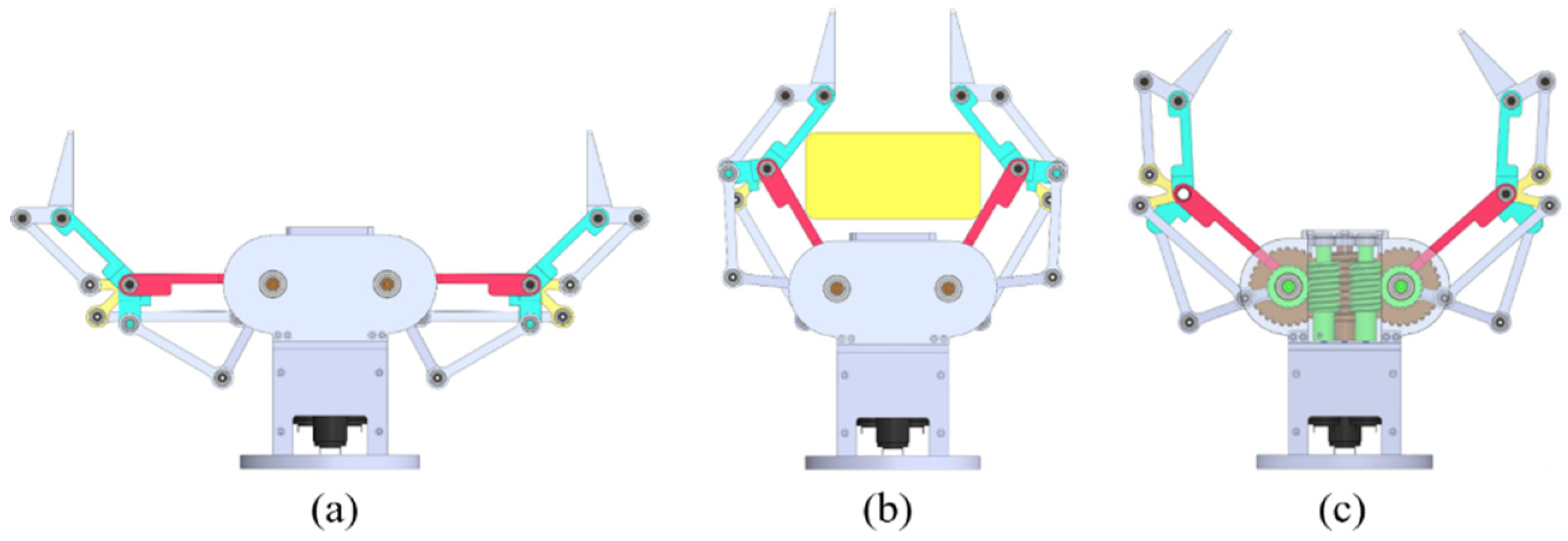
Figure 13a. It can be found that the workspace of the gripper is very big and the maximum span of the gripper is around 260 mm. The payload for parallel grasping is around 2.5 kg.
Figure 13b demonstrates the shape-adaptive grasping. Moreover, the orientation of the distal phalanx is decoupled from the open-close motion and can be actively adjusted as shown in
Figure 13c. Thus, the orientation of the distal phalanx can be maintained at a desired angle during grasping, even when the distal phalanx makes a contact with the supported environment accidentally as shown in
Figure 14. Hence, parallel grasping can be continued and we call this grasping mode ‘environmental contact-based grasping’. This grasping mode is very useful for grasping thin objects lying on flat surfaces. For many other grippers, instead, a combination of some new grasping strategy and special designs is required for picking up small objects lying on flat surfaces [
39,
47].
5.2. Analysis of the Environmental Contact-Based Grasping
The aforementioned contact-based grasping is very useful for picking up thin and small objects lying on flat surfaces. To ensure that the grasping is stable, a simple control algorithm might be required. As shown in
Figure 14b, the torsion spring will be twisted during the fingertip-surface-contact process. The angle between proximal and intermediate phalanxes will be continuously decreasing (
) until the fingertip makes contact with the object to be grasped. When the gripper finished contact-based grasping, an industrial robot will be controlled to lift up the gripper and object. During this lifting up process and before the fingertip totally leaves the supporting surface, the resistance torque of the torsion spring will try to force the proximal and intermediate phalanxes to move back to their home position, where the angle between them is designed as 135° (
). Thus, during the lifting up process, the distance between the two fingertips might increase or decrease, which depends on the finger structure and grasping state. If the distance between the two fingertips is trying to decrease, the resistance torque of the torsion spring will force the fingertip to grasp the object and the grasping is stable, i.e., the object will not fall down. However, if the distance between the two fingertips is trying to increase, the object might fall down if no gripper control is applied. Several hardware-based approaches could be used to solve this problem. For example, during the lifting up process, we can use a magnetic brake to lock the relative position between proximal and intermediate phalanxes. Installing an anti-moving back mechanism at the pivot joint where the torsion spring is installed is another approach [
11]. In this work, a simple control algorithm is used to ensure that the grasping is stable.
As the gripper is attached to a robot arm, we can control the lifting up motion of the robot arm and the closing motion of the gripper during lifting up process to make sure that the contact-based grasping is stable.
Figure 14b shows a reference state when the gripper moves upward with the robot arm but still in contact with the supporting surface. Taking the coordinates (x, z) of the point
into consideration, the problem can be stated as: when the coordinate z increases (lifted by the robot arm), find out how much the angle
should increase (controlled by the gripper) to ensure that the coordinate x is not increasing to maintain the grasping. The key here is to build the relationship between
and
. Referring to
Figure 14b, we have
The goal is to make the coordinate
keep constant. Differentiating the two terms in Equation (25) with respect to time, we have
From the first term of Equation (26), we have
Substituting Equation (27) into the second term of Equation (26), we can obtain
where
Differentiating Equation (30) with respect to time, we obtain
In this design,
, then
can be expressed as
Similarly,
and
can be expressed as
Substituting Equation (32) into the two terms of Equation (33) and differentiating them with respect to time yields
From Equation (34), we have
Substituting Equation (35) into Equation (31) and combining with Equation (27) results in
where
Combining Equations (28) and (36), we can obtain
Thus, to ensure that the parallel grasping is maintained during lifting, the closing speed of the gripper should be controlled to be larger than . where represents the lifting speed of the robot arm.
5.3. Experimental Evaluation
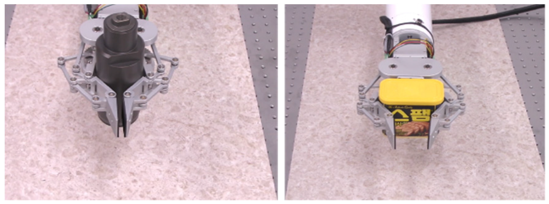
Figure 15 shows three examples of fingertip parallel grasping. A wide span allows this gripper to grasp a large variety of objects with different sizes.
Figure 16 demonstrates two examples of shape-adaptive grasping. As mentioned above, the orientation of the distal phalanx can be actively adjusted, which allows users to use pinch motion to grasp objects with irregular shape as shown in
Figure 17. For objects shown in
Figure 17b,c, there exists spare space between the object and the supported base. Actively controlled distal phalanx allows the gripper to scoop the object up from the bottom side.
Figure 17d demonstrates that by closing the distal phalanx, objects with lifting ears can be grasped similar to a caging grasp.
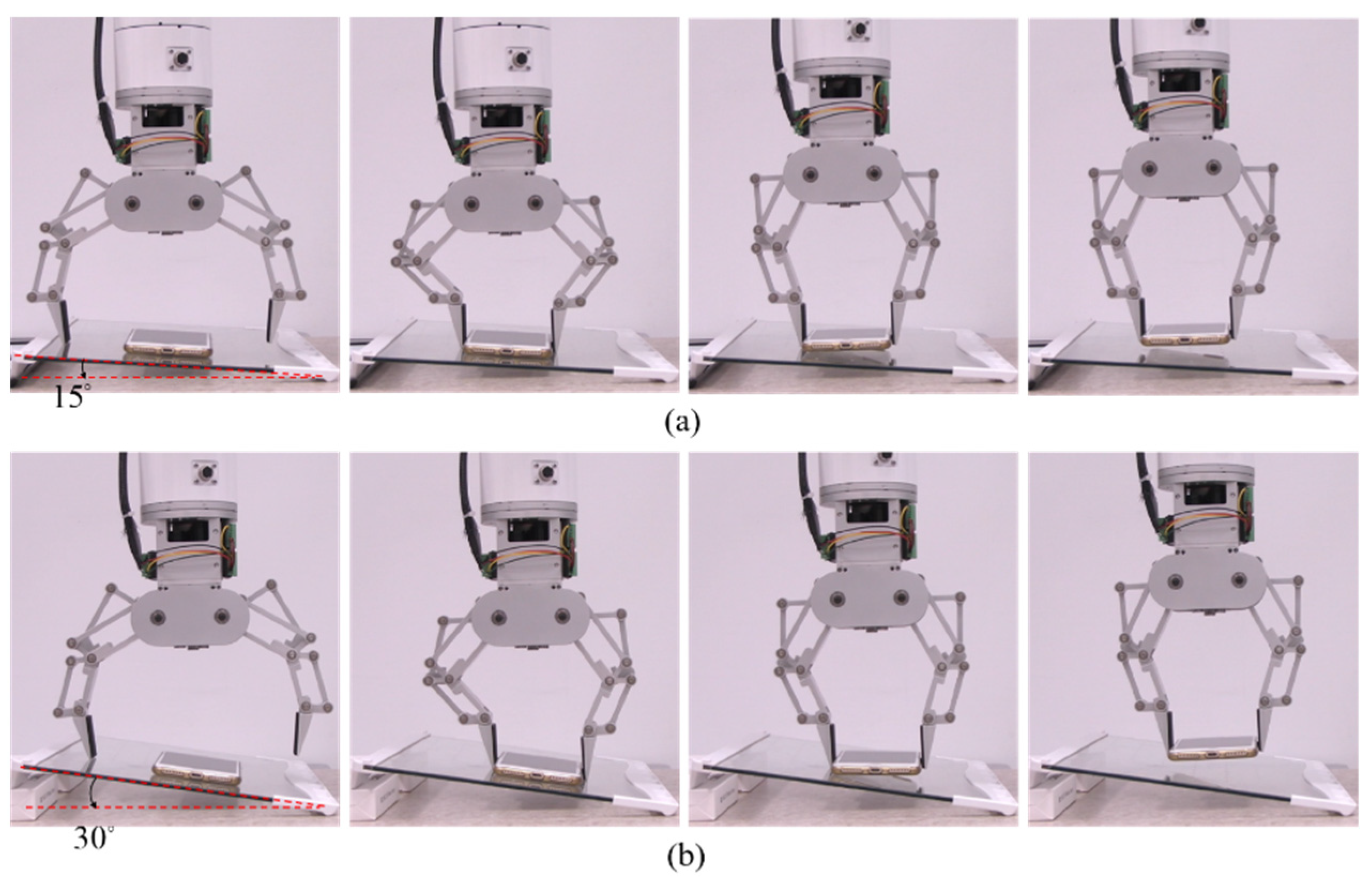
Figure 18 shows the grasping sequence while making contact with the supported base. Even in the scenario that the supported base is inclined, parallel grasping can still be achieved successfully as shown in
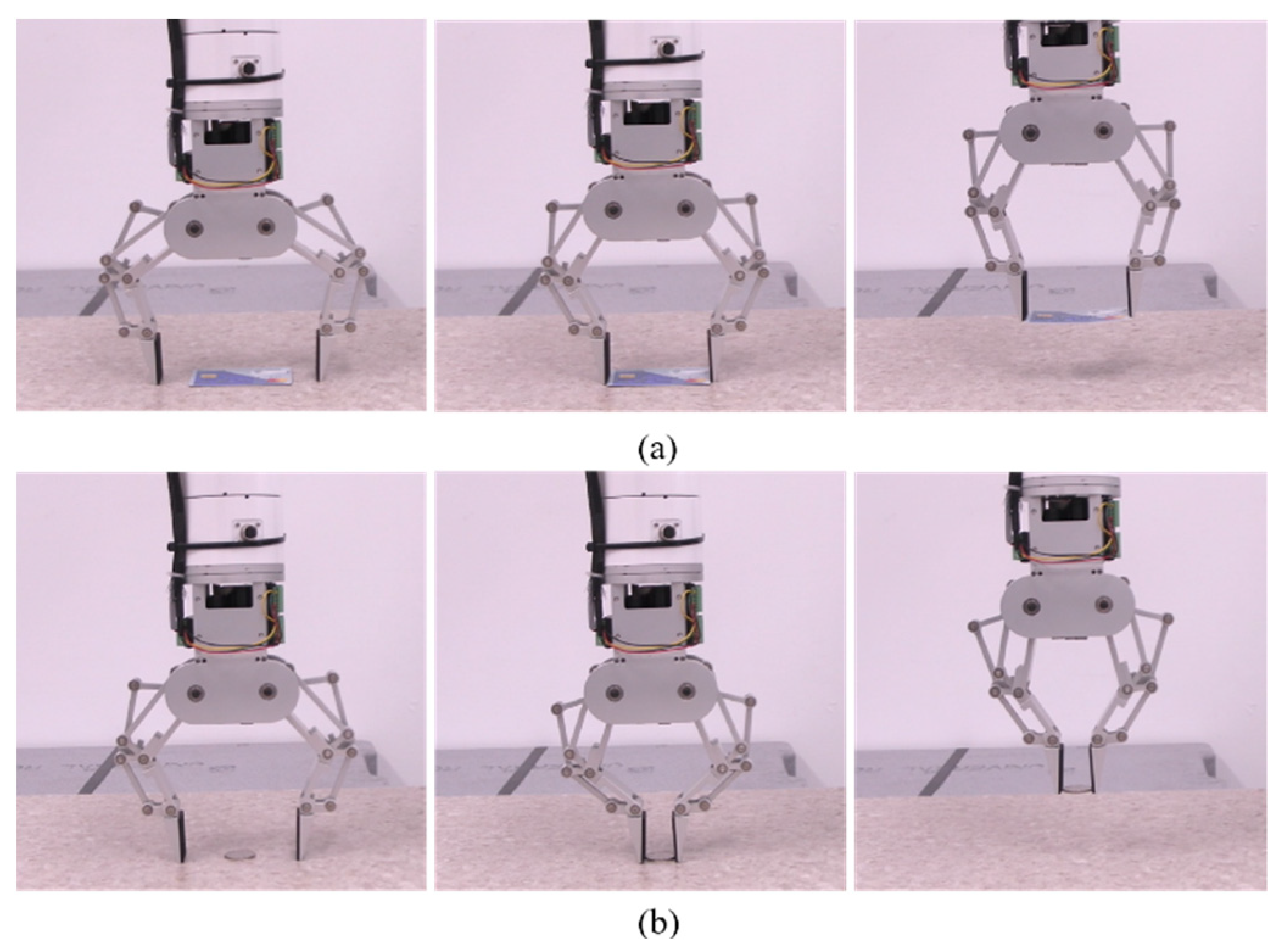
Figure 19. This is because each finger deflects upon contact with the base independently due to torsional spring and that the orientation of the distal phalanx can be independently controlled to maintain parallel grasping. Compared to other grippers, we found that it is also quite simple to use this gripper to pick up thin objects lying on a flat surface as shown in
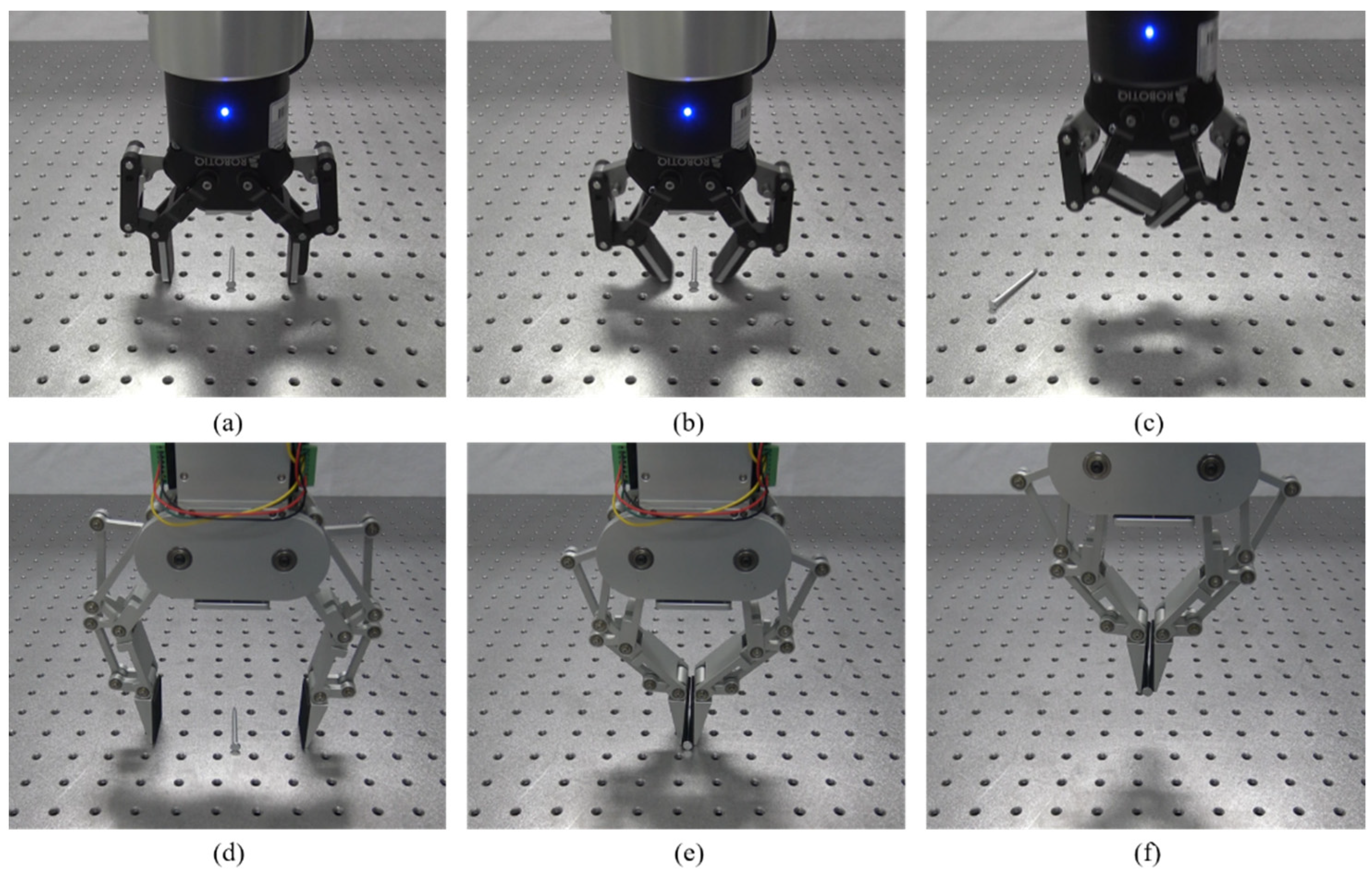
Figure 20. Many other grippers/hands might fail to grasp objects in such a simple manner because once contact was established with the supporting base, the orientation of the distal phalanx generally will be changed passively. Continuing closing the finger will result in unstable grasping of thin objects. One example of failure of contact-based grasp using a Robotiq 2-finger gripper is shown in
Figure 21a–c.
Figure 21d–f shows the success of grasping such a nail using the proposed gripper. Hence, to grasp such objects without making any contact with the supported base, a highly accurate calibration algorithm and vision system are generally required. For more details about the experiment, please refer to the video uploaded along with this manuscript.
6. Discussion
Different from many previous studies that use intuitive design and specific CAD-aided simulation to build robotic grippers, this paper presents an effort to establish a systematic approach that combines the dynamics and statics model of the robotic finger for the purpose of providing an analytical guidance for users to select appropriate torsion spring and finally come up with a suitable design.
While developing the quasi-static model of the robotic finger, friction terms at contact surfaces are ignored. Our primary goal is to investigate the capability of the robotic finger (and only the finger) to exert a wrench onto a fixed object. We are, therefore, not interested in the local properties of the contact, such as friction or geometry of the contact. In order to obtain simple and general results that can characterize the finger itself and not the system formed by the finger and the object, pure normal contact forces should be considered. These normal contact forces depend on the locations of contact points, actuation torque, and resistance torque exerted by the torsion spring. To determine them, we proceed with a quasi-static modelling of the finger by ignoring the friction term and fixing the object. Obviously, the friction coefficient at the contact surface can have an impact in terms of the grasp stability. In future studies, we will especially focus on the whole grasping system formed by the gripper and the object to investigate the influence of the friction in grasping.
As far as the grasping experiment is concerned, we note that only the open-loop control method was used to detect the object to be grasped and we did not apply the camera information into the controller. This is because we only want to demonstrate the performance of the gripper itself and the open-loop control method could greatly simplify the experiment. Object recognition definitely is another important research issue in robotic grasping and the conventional technique route is combining RGB-D camera (according to the relative configuration between the camera and robot, two approaches: eye to hand or eye in hand) with certain vision algorithms (especially the machine-learning-based approach) for detecting object postures. But it exceeds the scope of this paper which focuses on the modelling and design.
As far as the grasping force control is concerned, usually force sensors (e.g., tactile sensor attached to the finger pad) are required for providing high-accuracy grasping force control, also possible for detecting and avoiding object sliding during grasping. However, in the current design, we did not use any external force/tactile sensor to detect the grasping force. We are using the motor current as the feedback to control the velocity. For a certain object, we can approximately apply a certain grasping force by setting a certain motor current value as the feedback in the velocity controller. This is because the controller hardware (from the Faulhaber company, MCDC series) used in our gripper can only provide position and velocity control functions (but could provide the actual position, velocity, and current feedback value from the motor encoder). To be honest, this approach has low accuracy and much noise that might be caused by the friction of the power transmission system. As the example objects used in our experiment are relatively rigid, this approach works and did not break the object to be grasped. However, to grasp some soft and fragile object, we suggest using force/tactile sensors to avoid breaking the object to be grasped.
7. Conclusions
In this paper, we have presented a three-DOF linkage-driven robotic finger and developed a two-fingered underactuated gripper. The main theoretical contribution of this paper includes providing an analytical guidance for users to select appropriate parameters for the torsion spring at the passive joint by combining the dynamic and static grasp model of the underactuated finger and investigating the control strategy of environmental contact-based grasping.
Through multiple experiments, it is demonstrated that the first prototype of the two-finger underactuated gripper can be used to perform fingertip parallel grasping and shape-adaptive grasping successfully. During grasping household objects, especially those objects with low heights, a good calibration algorithm and highly accurate robot-vision system are generally required for avoiding making contact with the supporting surface. However, because visual localization errors, coordinate control errors of the industrial robot and robotic gripper, and uncertainties of the grasping environment always exist, the fingertip makes contact with the supporting surface frequently while grasping household objects that have varied shapes and sizes. Independent fingertip control and passive compliance caused by the underactuation design allow us to perform environmental contact-based grasping simply and robustly. Environmental-contact based grasping can be used to grasp low-height objects lying on a flat surface simply and efficiently. Comparatively, using most of other grippers to fulfill such tasks required high-precision calibration and control algorithms for avoiding collisions with the supporting surface. Future work includes using tactile sensors instead of motor current feedback for accurate grasping force control.
Author Contributions
Conceptualization, L.K. and B.-J.Y.; methodology, L.K. and B.-J.Y.; software, L.K. and S.-H.K.; validation, L.K. and S.-H.K.; formal analysis, L.K.; investigation, L.K.; writing—original draft preparation, L.K.; writing—review and editing, L.K. and B.-J.Y.; supervision, L.K. and B.-J.Y.; funding acquisition, L.K. and B.-J.Y. All authors have read and agreed to the published version of the manuscript.
Funding
This research was funded in part by the Innovation Program (grant number JYB202107) funded by Key Laboratory of Intelligent Perception and Systems for High-Dimensional Information of Ministry of Education (Nanjing University of Science and Technology), in part by Jiangsu Province’s “Double Innovation Ph.D.” (grant number JSSCBS20210206), and in part by the Technology Innovation Program (or Industrial Strategic Technology Development Program) (grant number 20001856, Development of Robotic Work Control Technology Capable of Grasping and Manipulating Various Objects in Everyday Life Environment Based on Multimodal Recognition and Using Tools) funded by the Ministry of Trade, Industry and Energy (MOTIE, Korea) and was supported by BK21 FOUR (Fostering Outstanding Universities for Research) funded by National Research Foundation of Korea (NRF).
Institutional Review Board Statement
Not applicable.
Informed Consent Statement
Not applicable.
Conflicts of Interest
The authors declare no conflict of interest.
Appendix A
By writing the closed-loop kinematic equation of the four-bar linkages ABCD shown in
Figure 4b, we have
Taking the derivative of Equation (A1), we can obtain the relationship between the independent and dependent joint variables as
where
and
are the Jacobians of the loop equations with respect to
and
, and they can be obtained as
By solving for
we form
as
Referring to
Figure 10a, the relationship between joint
and
can be found as
Differentiating Equation (A6), we have
where
and
can be found from Equation (10). They can be rewritten as
Combining Equations (A7) and (A8), the matrix
in Equation (11) that relates dependent joint
to
can be obtained as
The matrix
in Equation (12) that relates the actuated joint angle
to
, can be obtained as
Referring to
Figure 10a, the motion of the two contact points,
and
, can be obtained as
Taking the derivative of Equation (A11), we have
Hence, the
and
in Equation (13) can be obtained as
and
in Equation (13) can be formed as
As we only consider the normal forces at the contact points, the motion of the two contact points in the normal direction can be obtained as
Rewriting Equation (A15) in matrix form, we can have
Then
in Equation (14) can be found as
and
in Equation (14) can be formed as
Appendix B
Similar to the two-point contact, three-point contact can be achieved by adding one more active joint
. Firstly, the derivative of the motion of the first two contact points,
and
, can be obtained by rewriting Equation (A12) with respect to
as follows
Referring to
Figure 10b, the motion of the third contact point,
, can be obtained as
Taking the derivative of Equation (A21), we have
Hence, the
,
, and
in Equation (19) can be obtained as
and
in Equation (19) can be formed as
Similar to Equation (A15), the normal components of the motion at the three contact points can be obtained as
Rewriting Equation (A25) in matrix form, we have
Then
in Equation (20) can be found as
and
in Equation (20) can be formed as
References
- Jacobsen, S.; Iversen, E.; Knutti, D.; Johnson, R.; Biggers, K. Design of the Utah/M.I.T. Dextrous Hand. In Proceedings of the 1986 IEEE International Conference on Robotics and Automation (ICRA), San Francisco, CA, USA, 7–10 April 1986; pp. 1520–1532. [Google Scholar]
- Grebenstein, M.; Albu-Schäffer, A.; Bahls, T.; Chalon, M.; Eiberger, O.; Friedl, W.; Gruber, R.; Haddadin, S.; Hagn, U.; Haslinger, R.; et al. The DLR hand arm system. In Proceedings of the 2011 IEEE International Conference on Robotics and Automation, Shanghai, China, 9–13 May 2011; pp. 3175–3182. [Google Scholar]
- Shadow Robot Company. Design of a Dextrous Hand for Advanced CLAWAR Applications. Available online: http://www.shadowrobot.com/downloads/dextrous_hand_final.pdf (accessed on 14 October 2021).
- Bridgwater, L.B.; Ihrke, C.A.; Diftler, M.A.; Abdallah, M.E.; Radford, N.A.; Rogers, J.M.; Yayathi, S.; Askew, R.S.; Linn, D.M. The Robonaut 2 hand—Designed to do work with tools. In Proceedings of the 2012 IEEE International Conference on Robotics and Automation (ICRA), Saint Paul, MN, USA, 14–18 May 2012; pp. 3425–3430. [Google Scholar]
- Bicchi, A. Hands for dexterous manipulation and robust grasping: A difficult road toward simplicity. IEEE Trans. Robot. Autom. 2000, 16, 652–662. [Google Scholar] [CrossRef] [Green Version]
- Birglen, L.; Laliberté, T.; Gosselin, C.M. Underactuated Robotic Hands; Springer: Berlin/Heidelberg, Germany, 2007; Volume 40. [Google Scholar]
- Birglen, L.; Gosselin, C.M. Kinetostatic analysis of underactuated fingers. IEEE Trans. Robot. Autom. 2004, 20, 211–221. [Google Scholar] [CrossRef]
- Yamaguchi, K.; Hirata, Y.; Kosuge, K. Underactuated robot hand for dual-arm manipulation. In Proceedings of the 2015 IEEE/RSJ International Conference on Intelligent Robots and Systems (IROS), Hamburg, Germany, 28 September–2 October 2015; pp. 2937–2942. [Google Scholar]
- Kobayashi, A.; Yamaguchi, K.; Kinugawa, J.; Arai, S.; Hirata, Y.; Kosuge, K. Analysis of precision grip force for uGRIPP (underactuated gripper for power and precision grasp). In Proceedings of the 2017 IEEE/RSJ International Conference on Intelligent Robots and Systems (IROS), Vancouver, BC, Canada, 24–28 September 2017; pp. 1937–1942. [Google Scholar]
- Kragten, G.A.; Herder, J.L. The ability of underactuated hands to grasp and hold objects. Mech. Mach. Theory 2010, 45, 408–425. [Google Scholar] [CrossRef]
- Nishimura, T.; Mizushima, K.; Suzuki, Y.; Tsuji, T.; Watanabe, T. Variable-Grasping-Mode Underactuated Soft Gripper With Environmental Contact-Based Operation. IEEE Robot. Autom. Lett. 2017, 2, 1164–1171. [Google Scholar] [CrossRef] [Green Version]
- Chang, C.-M.; Gerez, L.; Elangovan, N.; Zisimatos, A.; Liarokapis, M. On Alternative Uses of Structural Compliance for the Development of Adaptive Robot Grippers and Hands. Front. Neurorobotics 2019, 13, 91. [Google Scholar] [CrossRef] [PubMed] [Green Version]
- Mitsui, K.; Ozawa, R.; Kou, T. An under-actuated robotic hand for multiple grasps. In Proceedings of the 2013 IEEE/RSJ International Conference on Intelligent Robots and Systems (IROS), Tokyo, Japan, 3–7 November 2013; pp. 5475–5480. [Google Scholar]
- Aukes, D.M.; Heyneman, B.; Ulmen, J.; Stuart, H.; Cutkosky, M.R.; Kim, S.; Garcia, P.; Edsinger, A. Design and testing of a selectively compliant underactuated hand. Int. J. Robot. Res. 2014, 33, 721–735. [Google Scholar] [CrossRef]
- Catalano, M.G.; Grioli, G.; Farnioli, E.; Serio, A.; Piazza, C.; Bicchi, A. Adaptive synergies for the design and control of the Pisa/IIT SoftHand. Int. J. Robot. Res. 2014, 33, 768–782. [Google Scholar] [CrossRef] [Green Version]
- Ozawa, R.; Hashirii, K.; Kobayashi, H. Design and control of underactuated tendon-driven mechanisms. In Proceedings of the 2009 IEEE International Conference on Robotics and Automation (ICRA), Kobe, Japan, 12–17 May 2009; pp. 1522–1527. [Google Scholar]
- Ren, Z.; Zhou, C.; Xin, S.; Tsagarakis, N. HERI hand: A quasi dexterous and powerful hand with asymmetrical finger dimensions and under actuation. In Proceedings of the 2017 IEEE/RSJ International Conference on Intelligent Robots and Systems (IROS), Vancouver, BC, Canada, 24–28 September 2017; pp. 322–328. [Google Scholar]
- Dollar, A.M.; Howe, R.D. The Highly Adaptive SDM Hand: Design and Performance Evaluation. Int. J. Robot. Res. 2010, 29, 585–597. [Google Scholar] [CrossRef]
- Ko, T. A Tendon-Driven Robot Gripper With Passively Switchable Underactuated Surface and its Physics Simulation Based Parameter Optimization. IEEE Robot. Autom. Lett. 2020, 5, 5002–5009. [Google Scholar] [CrossRef]
- Hussain, I.; Renda, F.; Iqbal, Z.; Malvezzi, M.; Salvietti, G.; Seneviratne, L.; Gan, D.; Prattichizzo, D. Modeling and Prototyping of an Underactuated Gripper Exploiting Joint Compliance and Modularity. IEEE Robot. Autom. Lett. 2018, 3, 2854–2861. [Google Scholar] [CrossRef]
- Chen, W.; Xiong, C.; Wang, Y. Analysis and Synthesis of Underactuated Compliant Mechanisms Based on Transmission Properties of Motion and Force. IEEE Trans. Robot. 2020, 36, 773–788. [Google Scholar] [CrossRef]
- Santina, C.D.; Piazza, C.; Grioli, G.; Catalano, M.G.; Bicchi, A. Toward Dexterous Manipulation With Augmented Adaptive Synergies: The Pisa/IIT SoftHand 2. IEEE Trans. Robot. 2018, 34, 1141–1156. [Google Scholar] [CrossRef]
- Birglen, L. Type Synthesis of Linkage-Driven Self-Adaptive Fingers. J. Mech. Robot. 2009, 1, 021010. [Google Scholar] [CrossRef]
- Wu, L.; Carbone, G.; Ceccarelli, M. Designing an underactuated mechanism for a 1 active DOF finger operation. Mech. Mach. Theory 2009, 44, 336–348. [Google Scholar] [CrossRef]
- Laliberté, T.; Gosselin, C. Actuation System for Highly Underactuated Gripping Mechanism. U.S. Patent No. 6,505,870, 14 January 2003. [Google Scholar]
- Demers, L.-A.A.; Lefrançois, S.; Jobin, J.-P. Gripper Having a Two Degree of Freedom Underactuated Mechanical Finger for Encompassing and Pinch Grasping. U.S. Patent 8,973,958, 10 March 2015. [Google Scholar]
- Kang, L.; Seo, J.; Yoon, D.; Kim, S.; Suh, I.H.; Yi, B. Design of a 3-DOF Linkage-Driven Underactuated Finger for Multiple Grasping. In Proceedings of the 2019 IEEE/RSJ International Conference on Intelligent Robots and Systems (IROS), Macau, China, 3-8 November 2019; pp. 5608–5613. [Google Scholar]
- Li, J.; Kong, Y.; Dong, M.; Jiao, R. Development of a linear-parallel and self-adaptive under-actuated hand compensated for the four-link and sliding base mechanism. Robotica 2021, 1–18. [Google Scholar] [CrossRef]
- Yao, S.; Ceccarelli, M.; Carbone, G.; Zhan, Q.; Lu, Z. Analysis and optimal design of an underactuated finger mechanism for LARM hand. Front. Mech. Eng. 2011, 6, 332. [Google Scholar] [CrossRef]
- Liu, C.-H.; Chiu, C.-H.; Hsu, M.-C.; Chen, Y.; Chiang, Y.-P. Topology and Size–Shape Optimization of an Adaptive Compliant Gripper with High Mechanical Advantage for Grasping Irregular Objects. Robotica 2019, 37, 1383–1400. [Google Scholar] [CrossRef]
- Kim, Y.; Song, H.; Maeng, C. BLT Gripper: An Adaptive Gripper With Active Transition Capability Between Precise Pinch and Compliant Grasp. IEEE Robot. Autom. Lett. 2020, 5, 5518–5525. [Google Scholar] [CrossRef]
- Watanabe, T.; Morino, K.; Asama, Y.; Nishitani, S.; Toshima, R. Variable-Grasping-Mode Gripper With Different Finger Structures For Grasping Small-Sized Items. IEEE Robot. Autom. Lett. 2021, 6, 5673–5680. [Google Scholar] [CrossRef]
- Rojas, N.; Ma, R.R.; Dollar, A.M. The GR2 Gripper: An Underactuated Hand for Open-Loop In-Hand Planar Manipulation. IEEE Trans. Robot. 2016, 32, 763–770. [Google Scholar] [CrossRef]
- Birglen, L. Design of a partially-coupled self-adaptive robotic finger optimized for collaborative robots. Auton. Robot. 2019, 43, 523–538. [Google Scholar] [CrossRef] [Green Version]
- Wang, Q.; Quan, Q.; Deng, Z.; Hou, X. An Underactuated Robotic Arm Based on Differential Gears for Capturing Moving Targets: Analysis and Design. J. Mech. Robot. 2016, 8, 041012. [Google Scholar] [CrossRef]
- Ozawa, R.; Mishima, Y.; Hirano, Y. Design of a Transmission With Gear Trains for Underactuated Mechanisms. IEEE Trans. Robot. 2016, 32, 1399–1407. [Google Scholar] [CrossRef]
- Quan, Q.; Wang, Q.; Deng, Z.; Jiang, S.; Hou, X.; Tang, D. A planetary gear based underactuated self-adaptive robotic finger. In Proceedings of the 2013 IEEE International Conference on Robotics and Biomimetics (ROBIO), Shenzhen, China, 12–14 December 2013; pp. 1586–1591. [Google Scholar]
- Zhang, W.; Che, D.; Liu, H.; Ma, X.; Chen, Q.; Du, D.; Sun, Z. Super under-actuated multi-fingered mechanical hand with modular self-adaptive gear-rack mechanism. Ind. Robot Int. J. Robot. Res. Appl. 2009, 36, 255–262. [Google Scholar] [CrossRef]
- Babin, V.; Gosselin, C. Picking, grasping, or scooping small objects lying on flat surfaces: A design approach. Int. J. Robot. Res. 2018, 37, 1484–1499. [Google Scholar] [CrossRef]
- Cerruti, G.; Chablat, D.; Gouaillier, D.; Sakka, S. ALPHA: A hybrid self-adaptable hand for a social humanoid robot. In Proceedings of the 2016 IEEE/RSJ International Conference on Intelligent Robots and Systems (IROS), Daejeon, Korea, 9–14 October 2016; pp. 900–906. [Google Scholar]
- Xu, K.; Liu, H.; Zenghui, L.; Du, Y.; Zhu, X. A single-actuator prosthetic hand using a continuum differential mechanism. In Proceedings of the 2015 IEEE International Conference on Robotics and Automation (ICRA), Seattle, WA, USA, 26–30 May 2015; pp. 6457–6462. [Google Scholar]
- Liu, H.; Zhao, L.; Siciliano, B.; Ficuciello, F. Modeling, Optimization, and Experimentation of the ParaGripper for In-Hand Manipulation Without Parasitic Rotation. IEEE Robot. Autom. Lett. 2020, 5, 3011–3018. [Google Scholar] [CrossRef]
- Cui, J.; Yan, S.; Hu, J.; Chu, Z. A metric to design spring stiffness of underactuated fingers for stable grasp. Robot. Auton. Syst. 2018, 102, 1–12. [Google Scholar] [CrossRef]
- Kang, L.; Seo, J.-T.; Kim, S.-H.; Kim, W.-J.; Yi, B.-J. Design and Implementation of a Multi-Function Gripper for Grasping General Objects. Appl. Sci. 2019, 9, 5266. [Google Scholar] [CrossRef] [Green Version]
- Gosselin, C.M.; Laliberté, T. Underactuated Mechanical Finger with Return Actuation. U.S. Patent No. 5,762,390, 9 June 1998. [Google Scholar]
- Motion, A. Available online: https://www.ansys.com/products/structures/ansys-motion (accessed on 1 December 2021).
- Odhner, L.U.; Ma, R.R.; Dollar, A.M. Precision grasping and manipulation of small objects from flat surfaces using underactuated fingers. In Proceedings of the 2012 IEEE International Conference on Robotics and Automation, Saint Paul, MN, USA, 14–18 May 2012; pp. 2830–2835. [Google Scholar]
Figure 1.
The grasping sequence of a three-phalanx underactuated finger.
Figure 1.
The grasping sequence of a three-phalanx underactuated finger.
Figure 2.
Illustration of the fingertip trajectory of rotational grippers during grasping.
Figure 2.
Illustration of the fingertip trajectory of rotational grippers during grasping.
Figure 3.
The design concept of a contact-based pinching grasp for grasping low-height objects.
Figure 3.
The design concept of a contact-based pinching grasp for grasping low-height objects.
Figure 4.
(a) A new three-phalanx robotic finger mechanism. (b) The underactuated type.
Figure 4.
(a) A new three-phalanx robotic finger mechanism. (b) The underactuated type.
Figure 5.
A comparison between the proposed finger mechanism and Sarah hand. (a) Proposed finger mechanism. (b) Parallel precision grasping of the proposed mechanism. (c) Power grasping of the proposed finger mechanism. (d) A general three-phalanx adaptive finger. (e) Parallel precision grasping of Sarah hand. (f) Power grasping of Sarah hand.
Figure 6.
Grasping sequences of different grasping modes. (a) Parallel grasping. (b) Shape-adaptive grasping.
Figure 6.
Grasping sequences of different grasping modes. (a) Parallel grasping. (b) Shape-adaptive grasping.
Figure 7.
Dynamic simulation in MATLAB. (a) The torque required at the active joint . (b) The torque required at the active joint . (c) The torque required at the virtual active joint .
Figure 7.
Dynamic simulation in MATLAB. (a) The torque required at the active joint . (b) The torque required at the active joint . (c) The torque required at the virtual active joint .
Figure 8.
Comparison of the analytical results from MATLAB with the simulation results from a commercialized dynamic simulator. (a) Error torque at joint . (b) Error torque at the joint .
Figure 8.
Comparison of the analytical results from MATLAB with the simulation results from a commercialized dynamic simulator. (a) Error torque at joint . (b) Error torque at the joint .
Figure 9.
Variation of the torque of the torsion spring during dynamic simulation by considering different preloading of the torsion spring. (a) Preloading of −50 Nmm (−0.05 Nm). (b) Preloading of −20 Nmm (−0.02 Nm).
Figure 9.
Variation of the torque of the torsion spring during dynamic simulation by considering different preloading of the torsion spring. (a) Preloading of −50 Nmm (−0.05 Nm). (b) Preloading of −20 Nmm (−0.02 Nm).
Figure 10.
Description of variables used for static grasp modeling. (a) Two-point contact. (b) Three-point contact.
Figure 10.
Description of variables used for static grasp modeling. (a) Two-point contact. (b) Three-point contact.
Figure 11.
One example of the two-point contact grasp. (a) Final configuration. (b) Variations of the contact forces exerted on the two phalanxes with respect to the spring preloading.
Figure 11.
One example of the two-point contact grasp. (a) Final configuration. (b) Variations of the contact forces exerted on the two phalanxes with respect to the spring preloading.
Figure 12.
The first prototype of a two-fingered underactuated gripper.
Figure 12.
The first prototype of a two-fingered underactuated gripper.
Figure 13.
Different grasping modes. (a) Parallel grasping. (b) Shape-adaptive grasping. (c) Adjusting the orientation of the distal phalanx of each finger.
Figure 13.
Different grasping modes. (a) Parallel grasping. (b) Shape-adaptive grasping. (c) Adjusting the orientation of the distal phalanx of each finger.
Figure 14.
Parallel grasping during making contact with the environment. (a) At the start point of the contact. (b) A reference state when the gripper moves upward with the robot arm but still in contact with the supported base.
Figure 14.
Parallel grasping during making contact with the environment. (a) At the start point of the contact. (b) A reference state when the gripper moves upward with the robot arm but still in contact with the supported base.
Figure 15.
Examples of the parallel grasping.
Figure 15.
Examples of the parallel grasping.
Figure 16.
Examples of the shape-adaptive grasping.
Figure 16.
Examples of the shape-adaptive grasping.
Figure 17.
Examples of grasping by using pinch motion of the distal phalanx. (a) Grasping a baseball. (b) Grasping a roll of toilet paper. (c) Grasping a bowl. (d) Grasping a cup through caging.
Figure 17.
Examples of grasping by using pinch motion of the distal phalanx. (a) Grasping a baseball. (b) Grasping a roll of toilet paper. (c) Grasping a bowl. (d) Grasping a cup through caging.
Figure 18.
Grasping sequence while making contact with a flat surface.
Figure 18.
Grasping sequence while making contact with a flat surface.
Figure 19.
Grasping sequence while making contact with an inclined base. (a) The inclined angle of 15°. (b) The inclined angle of 30°.
Figure 19.
Grasping sequence while making contact with an inclined base. (a) The inclined angle of 15°. (b) The inclined angle of 30°.
Figure 20.
Examples of grasping thin objects. (a) A bank card. (b) A coin.
Figure 20.
Examples of grasping thin objects. (a) A bank card. (b) A coin.
Figure 21.
Comparison of a commercial Robotiq 2-finger gripper and the proposed gripper during grasping a nail. (a–c) Failure of grasping the nail using Robotiq gripper. (d–f) Success of grasping the nail using the proposed gripper.
Figure 21.
Comparison of a commercial Robotiq 2-finger gripper and the proposed gripper during grasping a nail. (a–c) Failure of grasping the nail using Robotiq gripper. (d–f) Success of grasping the nail using the proposed gripper.
Table 1.
Kinematic parameters 1 of the robotic finger.
Table 1.
Kinematic parameters 1 of the robotic finger.
| Length (mm) | Length (mm) | Angle (Deg) |
|---|
| | |
| | |
| | |
| | |
| | ( is Constrained by the mechanical stopper) |
| |
Table 2.
Specifications of the actuation system.
Table 2.
Specifications of the actuation system.
| FAULHABER | Motor 1 1 | Motor 2 2 | Motor 3 2 |
|---|
| Motor type | 1724T012SR | 1717T012SR | 1717T012SR |
| Rated torque | 4.5 Nmm | 2.1 Nmm | 2.1 Nmm |
| Controller type | MCDC 3006 S | MCDC 3006 S | MCDC 3006 S |
| Publisher’s Note: MDPI stays neutral with regard to jurisdictional claims in published maps and institutional affiliations. |
© 2021 by the authors. Licensee MDPI, Basel, Switzerland. This article is an open access article distributed under the terms and conditions of the Creative Commons Attribution (CC BY) license (https://creativecommons.org/licenses/by/4.0/).
