Article

Optimization and Control of a Planar Three Degrees of Freedom Manipulator with Cable Actuation

Department of Mechanic and Mechatronics, Faculty of Mechanical Engineering, Czech Technical University in Prague, Technická 4, 160 00 Prague, Czech Republic
*
Author to whom correspondence should be addressed.
Machines 2021, 9(12), 338; https://doi.org/10.3390/machines9120338
Submission received: 22 October 2021 / Revised: 26 November 2021 / Accepted: 2 December 2021 / Published: 7 December 2021
(This article belongs to the Section Machine Design and Theory)

Abstract

:
The paper analyzes a planar three degrees of freedom manipulator with cable actuation. Such a system can be understood as a special type of hybrid parallel kinematic mechanism composed of the rigid serial chain and the additional auxiliary cable system. The advantage of the auxiliary cable mechanism is the ability to reconfigure the whole system. The fulfillment of sufficient prestressing is the constraint of the optimization process. Computed Torque Control with a cable force distribution algorithm is implemented. The control algorithm performance is examined on different trajectories, including non-smooth motion requests, and its robustness is tested by randomly generated errors of the model parameters in regulators. The results demonstrate that the optimized structure is capable of controlling the manipulator motion and keeping the cable prestressing within the given limits.

Graphical Abstract

1. Introduction

Robots and manipulators with serial kinematics totally dominate in all industrial applications and have many advantages (e.g., large workspace [1]), and an end-effector represents the variety of possibilities (gripper, active component or tool [2]). However, the disadvantage is undoubtedly the worse dynamics (e.g., the low effective stiffness and damping [3]). New improvements in vibration suppression and motion control of the robot/manipulator end-effector are still highly in demand. Parallel kinematics, which theoretically represents some alternative, typically has better dynamic properties but usually has a high number of expensive, precise components on the other hand (such as joints and arms) and typically more limited workspace.
The combination of a robot/manipulator with a serial chain with an auxiliary cable mechanism is some trade-off between these two possibilities. Such a system could be understood as a special type of the hybrid parallel kinematic mechanism composed of the rigid serial chain and the additional auxiliary cable system. The advantage of the auxiliary cable mechanism is the ability to reconfigure a manipulator-cable system (Figure 1).
Considering weight reduction and cable systems, one could mention tensegrity structures (consisting of members under tension that are contiguous and members under compression that are not), which bring, on the one hand, the effective ratio of mass to stiffness [4] and are very popular in many areas: spatial robot [5], stacked tensegrity manipulator [6], tensegrity bridge, tensegrity “mobot” [7], etc. However, on the other hand, their dynamic properties are generally worse than the manipulators/robots with joints.
Generally, cable-controlled mechanisms [8] could be a combination of a pure serial structure and a tensegrity of the higher-order, e.g., the spherical mechanisms HexaSphere [9] and QuadroSphere [10]. Another special structure is a plant-inspired cable-driven manipulator [11]. However, parallel structures consisting of cables with negligible flexural stiffness [12] have to deal with the problem of complex vibrations, and the redundancy brings problems to a control algorithm [13]. Many approaches are focused on eliminating problems in the form of advanced methods of control and trajectory planning [14,15]. On the other hand, the redundancy of actuators could eliminate workspace singular positions and improve other parameters of a mechanism [16] (e.g., a hyper-redundant manipulator [17]).
The above-mentioned structures are all demonstrated in Figure 2. Firstly, the serial three-arm manipulator (Figure 2a) is extended to a parallel cable-driven mechanism (Figure 2b). In Figure 2c, there is an extension shown to a potential tensegrity manipulator derived from Figure 2b. This work is aimed at the interphase structure, which potentially represents the step forward to the tensegrity structure. The chosen parallel kinematic mechanism is cable-driven only.
The paper deals with the combination of a serial structure and cables, which closes the kinematic loops and increases stiffness, which we consider as an interesting way of improving dynamic properties. Cables contrary to rigid components of parallel mechanisms allow easy reconfiguration (disconnect/connect), are simple and light. The paper, therefore, analyzes the issue of controllability of a serial chain using cables in a certain section of the workspace. Moreover, there is the idea of reconfigurability of the cable connection for different sets of operations. This is the reason why we consider analyses and optimization of serial chains controlled by cables essential for this research.
The chosen design, number of cables and cable tension, are described in Section 2. The dynamic model with extensible cables is assembled in Section 3. Once the mechanism and its dynamic model are defined, the structure optimization follows. Local and global optimization methods are used (Section 4). To control the mechanism, the Computed Torque method is implemented with two different regulators. The distribution of cable force is described in Section 5. Finally, the simulation results are shown.

2. Design of the Cable-Driven Manipulator

2.1. Three Degrees of Freedom Planar Manipulator

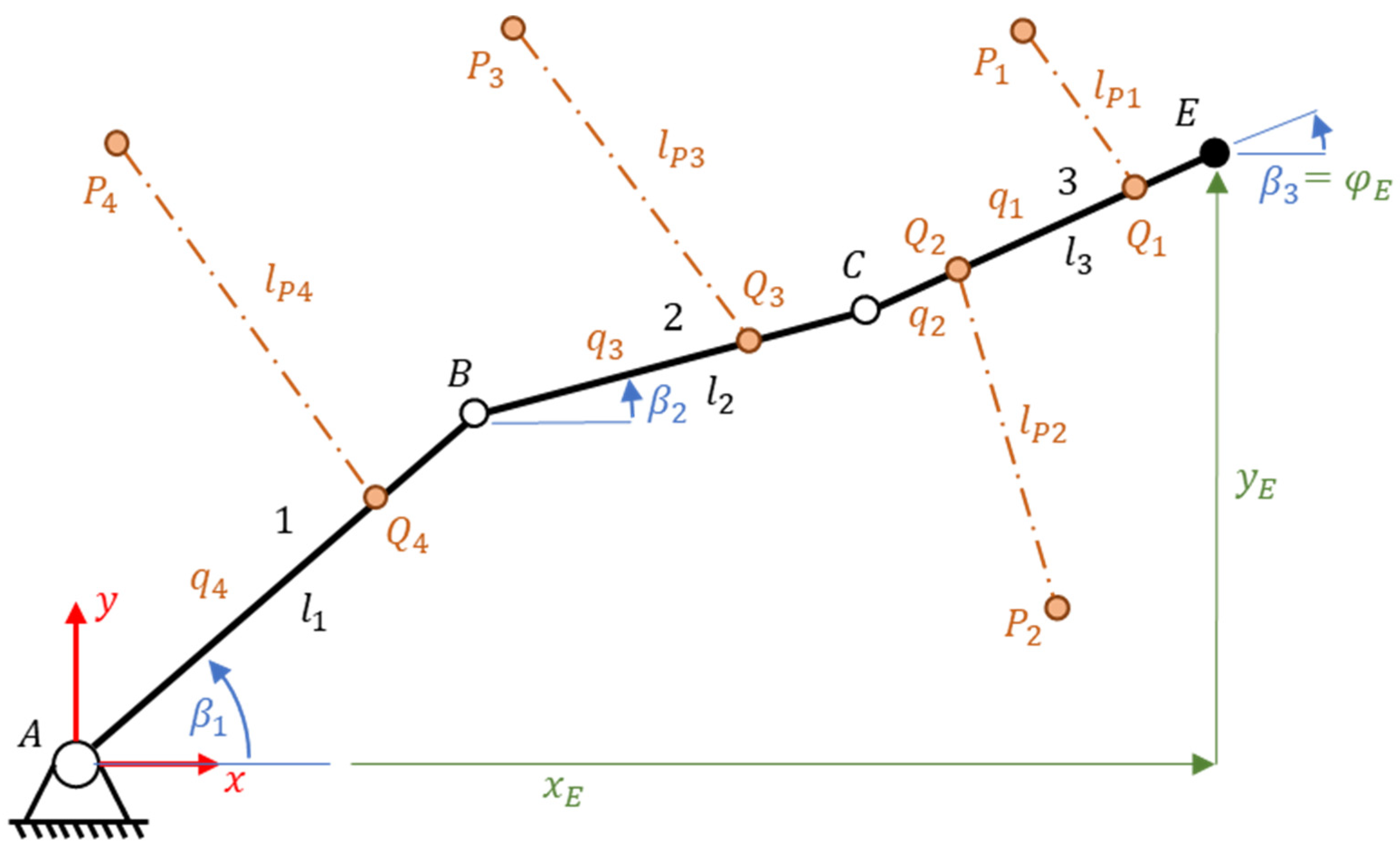
The chosen planar cable-driven three-links manipulator is schematically shown in Figure 3. The lengths of the links are l 1 , l 2 and l 3 , respectively. Points A, B and C represent rotational joints. The global Cartesian coordinate system x y is located at point A. The last point E represents the end-effector of the manipulator (the trajectory is planned for this point). The points P i are the pulley outlets, which are considered fixed in this step. The l P i = | P i Q i | are the active cable length where the points Q i defines the cable position on the links for i = 1 , , 4 and q 1 = | C Q 1 | , q 2 = | C Q 2 | , q 3 = | B Q 3 | and q 4 = | A Q 4 | . The three independent coordinates are chosen in two sets:
  • Absolute angle of every link: β 1 , β 2 , β 3   control algorithm
  • Absolute angle and position of the end-effector: x E ,   y E , φ E   optimization algorithm

2.2. Number of Cables of the Manipulator

The number of cables should be greater than the number of degrees of freedom (DoF) to reach the desired controllability of the manipulator [18]. This often leads to a redundant cable system. On the one hand, this idea can be easily supported since a cable is not able to transfer a compressive force but only a tensile force. On the other hand, the compressive force can be replaced by the gravitational force when the material body tightens the cables by its own weight. However, the gravitational force has limitations. For a spatial body with six DoF, there are approaches considering seven cables if all the cable outlets of the pulleys are located above the body, and gravitational force is considered in the control strategy. In the case of an intangible body, it is necessary to have a proper cable configuration, which enables all cables to tension each other and keep this pretension within certain limits (e.g., configuration with eight cables above and below the body in [19]). It is also necessary to mention the concept of static stability [20]. The configuration with seven cables above the body and gravitational force is significantly less stable against any external force than the configuration with eight cables above and under the body.
The number of cables for the planar three degrees of freedom manipulator is investigated in [18] and given by the formula
n c a b l e s = n ° + 1 .
The main effort of this work is to comprehensively investigate configuration where the workspace is, on the one side, the serial mechanism, and auxiliary cable system on the other side. Our work is aimed to reach the complex controllability using cables only, without any other actuation, even though the joint actuation is considered in the final application (Figure 1) (dynamic model is assembled considering joint actuation as well). Considering the gravitational forces, one can prestress the cables. However, the investigated control method should be independent of them. Therefore, the following discussion of the issue will be specified for the planar manipulator with three degrees of freedom controlled by four cables only where four cables are chosen from (1).

2.3. Cable Placement/Connection with Serial Structure

The schematic representation of cables placed on the planar manipulator is shown. The locations are based on the following consideration: the end-effector must be able to move in the sense of rotation. For this reason, it is necessary to connect the last link with at least two cables and the previous link with the third cable. The remaining fourth cable is then placed on the remaining first link.

2.4. Cables Tension and Force Distribution

A very important role in a control algorithm of the cable-driven manipulator is the force distribution into the individual cables. The investigated manipulator, whose structure is considered serial, is controlled by cables attached in parallel. The whole structure, thus, represents a serial-parallel arrangement, which has a redundant number of cables (four cables vs. three DoF manipulators). Therefore, the required action cannot be directly assigned to each motor. The topic of cable-driven manipulators is also discussed in [21], where it specifically investigates the case of a parallel spatial manipulator with n DoF ( n D o F ), which is controlled by ( n D o F + 2 ) cables. Such an algorithm is processed for six DoF and eight cables in [22].
A centralized control model is chosen to control the above series-parallel structure of the manipulator. All actuators are controlled at once by transforming the required force effects on the individual links of the manipulator.
Note 1: The decentralized model is a control structure where each cable is controlled by its own regulator. However, there may be situations where the regulators of two or more cables increase the action on each other—they “stretch”. In this case, it is not an attempt to pretension the cable because the regulators do not know about each other.
Note 2: If the regulators are not properly tuned, the action can grow above all limits, and there is a risk of rope breakage or motor overload. This is true for both centralized control and decentralized control.
The required moments acting on the manipulator links are obtained by the “Computed Torque” method, which uses inverse dynamics to convert the action intervention (the acceleration of the independent coordinates) into the moments that act on the individual links of the manipulator (using inverse dynamics). The required force effects in a serial structure without cables are provided by motors in the joints. These moments are transformed in the next step using the transposed Jacobi matrix J T . Furthermore, J T = W is introduced, where W is the “Wrench” matrix. In this case, the Jacobi matrix represents the matrix of the transfer between the cables and the independent coordinates, and one has
M M = W S = J T S
where M M is the vector of required moments and S is the vector of the required cable forces. One has more unknowns than equations, and thus, the solution is not unique (redundant number of cables). One way to find the solution is to use the Moore–Penrose pseudoinversion
W + = W T ( W W T ) 1
The force vector can now be expressed as
S 0 = W + M M = W T ( W W T ) 1 M M .
It should be noted that pseudoinversion has the following properties when solving a system of linear equations [3]:
  • For any dimension of the vector of unknown S the pseudoinversion of the matrix W of the solution is calculated in the sense of minimizing the Euclidean norm W S M M .
  • If the matrix W has dependent columns (more unknowns than equations), then the pseudoinversion determines the solution S 0 in the sense of minimizing the Euclidean norm S .
It follows from the above two properties that Equation (4) determines the energetically minimum required force effect for motors S 0 . However, such a solution contains both tensile and compressive forces, which is unacceptable for cable control.
The vector S 0 is a vector that represents the minimum energy solution of Equation (2). However, this solution is not unique, and any solution in the form N λ S can be added to it, where λ S is a parameter and N is generated from null space of matrix W and meets the orthonormality condition N T N = I . All solutions of Equation (2) are in the form
S = S 0 + N λ S
It is now possible to vary the resulting S . This strategy could be used if it is necessary to keep the forces in the motors that control the cables within certain limits. The problem can be written as a double inequality with the parameter λ S
S m i n S 0 + N λ S S m a x
The force vectors in the cables are introduced in the dynamic model to calculate the matrix W so that the positive sign represents the tensile force and the negative sign, the compressive force. It follows that the interval, which defines the possible motor load, is 0 , S m a x . By introducing this restriction, Equation (6) can be rewritten into
S m i n S 0 N λ S S m a x S 0
Let us assume that the interval 0 , S m a x is fixed, where S m a x determines the maximum force in the cable. Then it is possible to determine λ S m i n and λ S m a x
λ S m i n = N T ( S m i n S 0 ) ,   λ S m a x = N T ( S m a x S 0 ) .
λ S is subsequently kept in the middle of the interval λ S m i n , λ S m a x during control, which changes over time (note that Section 5.4 discusses an approach that does not use pseudoinversion of the matrix W but the determination of the parameter λ S is given by SVD decomposition. Such an approach is equivalent and gives the same results).

3. Dynamic Model of the Manipulator

The independent coordinates β 1 , β 2 and β 3 are chosen to assemble a dynamic model (DM). The DM is built in three steps:
  • Vector method (constraints between dependent and independent coordinates)
  • Newton–Euler dynamics Equations
  • Accelerations of mass centers of each link
Vector method (step N.1)
The vector method determines the relationship between dependent and independent coordinates. The number of independent vector loops is one [23] and is selected by the following points A B C E A . The vector Equation is
0 = b 1 + b 2 + b 3 + b 4 + b 5
and can be written in direction x as 0 = 1 5 b i c o s β i and in direction y as 0 = 1 5 b i s i n β i . Overview of parameters b i and β i are shown in Table 1.
In the next step, the vector of Equation (9) is derived, and one can write J q q ˙ + J z z ˙ = 0 , where the J q , q ˙ , J z and z ˙ are shown in Equation (10), respectively.
[ b 1 s i n β 1 b 2 s i n β 2 · b 3 s i n β 3 b 1 c o s β 1 b 2 c o s β 2 · b 3 c o s β 3 ] [ β 1 ˙ β 2 ˙ β 3 ˙ ] + [ c o s β 5 c o s β 4 s i n β 5 s i n β 4 ] [ x ˙ E y ˙ E ] = 0
The velocities of dependent coordinates are z ˙ = ( J z ) 1 J q q ˙ . The second derivation of the vector of Equation (9) is written in the form
J q q ¨ + J z z ¨ + j q z = 0
where J q and J z are known, and j q z is
j q z = [ b 1 c o s β 1 β 1 2 ˙ b 2 c o s β 2 β 2 2 ˙ b 3 c o s β 3 β 3 2 ˙ b 1 s i n β 1 β 1 2 ˙ b 2 s i n β 2 β 2 2 ˙ b 3 s i n β 3 β 3 2 ˙ ]
Newton–Euler equations (step N.2)
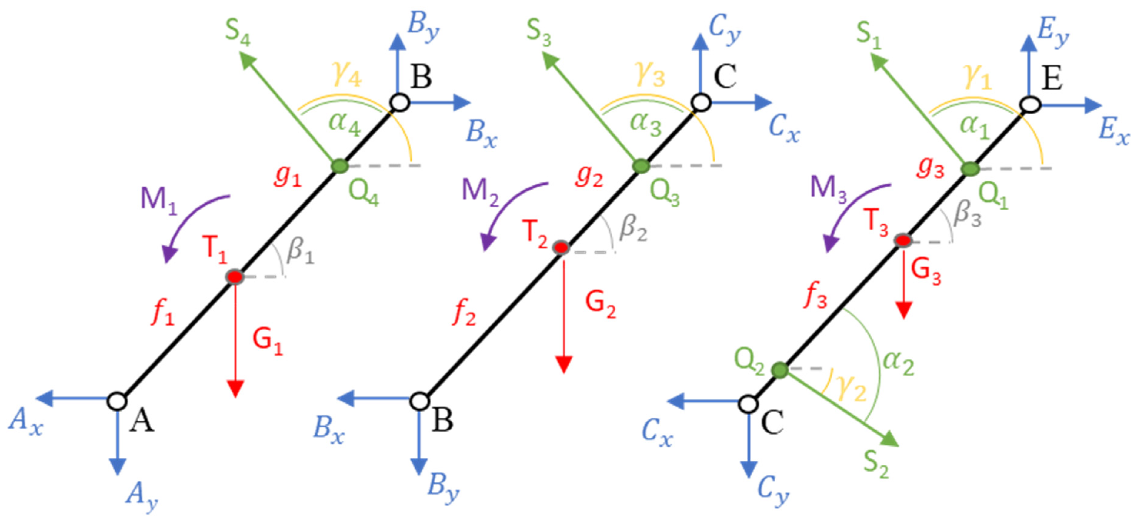
Newton–Euler (NE) equations for each manipulator’s arm are constructed. The free-body diagrams are shown in Figure 4. Equations are shown in Equation (14) for the first arm to illustrate the NE equations. The other two arms are given analogously. Constants f i and g i are introduced so that l i = f i + g i . The points T i are the centers of gravity (CoG). G i = m i g are the gravitational forces. Finally, the NE equations are written in the matrix form
M a = D R + Q
where M = d i a g [ m 1 ,   m 1 , I 1 S 1 , m 2 ,   m 2 , I 2 S 2 , m 3 ,   m 3 , I 3 S 3 ] is diagonal mass matrix, a = [ x ¨ 1 , y ¨ 1 , β ¨ 1 , x ¨ 2 , y ¨ 2 , β ¨ 2 , x ¨ 3 , y ¨ 3 , β ¨ 3 ] T is the vector of acceleration ( x i and y i are CoG coordinates), matrix D is defined in Equation (15), R = [ A x , A y ,   B x , B y , C x , C y ] T is the vector of reaction forces and Q is vector of external forces (Equation (16)).
X :       m 1 x 1 ¨ = B x A x + S 4 c o s   γ 4   Y :       m 1 y 1 ¨ = B y A y + S 4 s i n   γ 4 G 1 M :       I 1 S 1 β 1 ¨ = B y g 1 c o s β 1 B x g 1 s i n β 1 A x f 1 s i n β 1 + A y f 1 c o s β 1 + S 4 ( q 4 f 1 ) s i n   α 4 + M 1
D = [ 1 0 1 0 0 0 0 1 0 1 0 0 f 1 s i n β 1 f 1 c o s β 1 g 1 s i n β 1 g 1 c o s β 1 0 0 0 0 1 0 1 0 0 0 0 1 0 1 0 0 f 2 s i n β 2 f 2 c o s β 2 g 2 s i n β 2 g 2 c o s β 2 0 0 0 0 1 0 0 0 0 0 0 1 0 0 0 0 f 3 s i n β 3 f 3 c o s β 3 ] .
Q = [ S 4 c o s γ 4 S 4 s i n γ 4 G 1 S 4 ( q 4 f 1 ) s i n α 4 + M 1 S 3 c o s γ 3 S 3 s i n γ 3 G 2 S 3 ( q 3 f 2 ) s i n α 3 + M 2 S 1 c o s γ 1 + S 2 c o s γ 2 S 1 s i n γ 1 + S 2 s i n γ 2 G 3 S 1 ( q 1 f 3 ) s i n α 1 + S 2 ( q 2 f 3 ) s i n α 2 + M 3 ]
Acceleration of the CoG of each arm (step N.3)
The positions of the CoG of each arm are written in the global coordinate system. Equation (17) illustrates the equations for the second arm in x and in y , respectively,
x 2 = l 1 c o s β 1 + f 2 c o s β 2                               y 2 = l 1 s i n β 1 + f 2 s i n β 2
and the second derivation in x and y , respectively, in Equations (18) and (19)
x ¨ 2 = l 1 s i n β 1 β 1 ¨ l 1 c o s β 1 β 1 2 ˙ f 2 s i n β 2 β 2 ¨ f 2 c o s β 2 β 2 2 ˙
y ¨ 2 = l 1 c o s β 1 β 1 ¨ l 1 s i n β 1 β 1 2 ˙ + f 2 c o s β 2 · β 2 ¨ f 2 s i n β 2 β 2 2 ˙
Equations for the remaining arms are assembled in the same way. Equations are then written in the matrix form as
a = V q q ¨ + V z z ¨ + a q z ,
where V q and V z are given in Equation (21) and a q z in Equation (22).
V q = [ f 1 s i n β 1 0 0 f 1 c o s β 1 0 0 1 0 0 l 1 s i n β 1 f 2 s i n β 2 0 l 1 c o s β 1 f 2 c o s β 2 0 0 1 0 0 0 g 3 s i n β 3 0 0 g 3 c o s β 3 0 0 1 ] V z = [ 0 0 0 0 0 0 0 0 0 0 0 0 1 0 0 1 0 0 ]
a q z = [ f 1 c o s β 1 β 1 2 ˙ f 1 s i n β 1 β 1 2 ˙ 0 l 1 c o s β 1 β 1 2 ˙ f 2 c o s β 2 β 2 2 ˙ l 1 s i n β 1 β 1 2 ˙ f 2 s i n β 2 β 2 2 ˙ 0 g 3 c o s β 3 β 3 2 ˙ g 3 s i n β 3 β 3 2 ˙ 0 ]
Assembly of the Dynamic Model
To assemble the DM Equations (11), (13) and (20) are written together
[     M D       0           0 I 0 V z V q 0 0       J z         J q     ] [ a R z ¨ q ¨ ] = [ Q i       a q z j q z ]
The form is obviously A x = b . The solution is x = ( A ) 1 b . The input to DM is cable force vector S = [ S 1 , S 2 , S 3 , S 4 ] T . Moments M M = [ M 1 , M 2 , M 3 ] T are used only as auxiliary inputs for the transformation to cable forces. Finally, the output q ¨ is integrated twice ( q ˙ and q ) and used as an input to DM.

3.1. Geometrical Extension for a Pulley

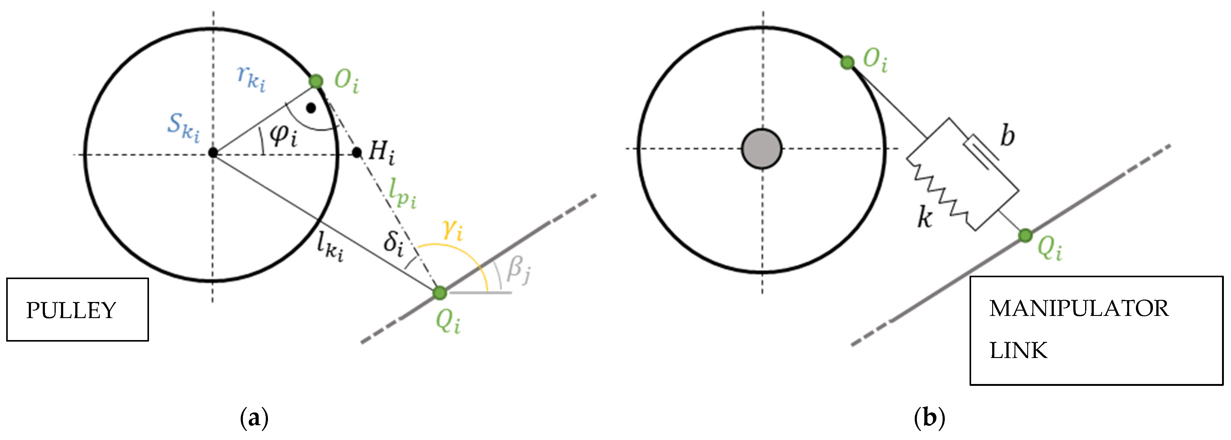
The following model simulates a moving point on a pulley, where points P i are replaced by the moving points O i ,   i = 1 , 2 , 3 , 4 (the fixed points P i are used for the purpose of optimization). S k i and r k i are the centers and the radiuses of the pulleys, respectively. The distance l k i is defined as l k i = | S k i Q i | . One can write for l p i
l p i = + l k i 2 r k i 2 .
The angle δ i ( 0 , π / 2 ) is given by δ i = s i n 1 ( r k i l k i ) and let denote θ i = γ i + δ i . Now, φ i is expressed as (the triangle S k i H i O i → the sum of the interior angles of triangle is π )
π = π 2 + φ i + ( π γ i )                     φ i = π 2 + γ i
Finally, the position of the point O i is
x O i = l k i c o s θ i + r k i c o s φ i = l p i c o s γ i , y O i = l k i s i n θ i + r k i s i n φ i = l p i s i n γ i .

3.2. Extensible Cable Model with Pulley

Cables are considered inextensible for the purpose of optimization ( | P i Q i | ). In the dynamic model, the extensible model of the cable and dynamic model of the pulley is implemented. The flexibility of a cable is modeled by a spring and a parallel damper (Figure 5b). The relationship for each cable is defined as
S c = S k + S b = k c a b l e Δ l C + b c a b l e Δ l C ˙ ,
where S c is the force acting on the manipulator link, S k is the force generated by the spring, S b is the force generated by the damper, k c a b l e is the cable stiffness, b c a b l e (the cable stiffness and damping are supposed to be the same for all cables) is the cable damping, Δ l C is the total cable elongation and Δ l C ˙ is the corresponding time derivative. The total elongation is determined by
Δ l C i = l p i l p 0 i r k i φ i ,
where l p 0 i is the initial cable length determined by the initial manipulator configuration, l p i is given by the actual manipulator configuration and r k i φ i represents a pulley motion (the initial condition is set as φ i 0 = 0 ). The dynamic pulley model is given as
I i P i φ ¨ i + b p φ ˙ i = ( S c i S i ) r k i ,
where I i P i is moment of inertia of a pully, S i r k i is an input moment from a regulator and b p φ ˙ i is a pulley damping moment.

4. Optimization of the Manipulator Structure

4.1. Optimization Parameters

The fixed points P i are chosen for the optimization purpose (the cable length is l p i = | P i Q i | ). The points Q i represent the cable connections with the manipulator link and the lengths q i determine the position of the cable connection (Figure 3). A parameter t i 0 , 1 is introduced to normalize the distances as follows:   t i = q i / l i ,   i = 1 , 2 , 3 , 4 . The t i are chosen in the interval t i 0.05 , 0.95 to avoid the joints areas. The overview is in Table 2.
Finally, the last optimization parameters are l 1 ,   l 2 and l 3 with limited interval l J 0 , 10 ,     j = 1 , 2 , 3 . To summarize, all chosen parameters are P 1 ,   P 2 , P 3 , P 4 , t 1 , t 2 , t 3 , t 4 , l 1 ,   l 2 and l 3 .

4.2. Workspace

The workspace of the manipulator is chosen as a square area with given dimensions, which also normalizes the optimization parameters (determines the scale) and is based on the idea of the local manipulator stiffness improvement. The rotation of the end-effector is described by angle ψ with the range bounded by ψ m i n and ψ m a x (this continuous range is replaced by a set of discrete points for the purpose of optimization). The chosen setup for the optimization is a set of 468 positions of the manipulator (36 positions and 13 rotations in every position).

4.3. Cost Function (CF)

Three partial cost functions are used for a mechanism with more DoF than one [24]. They are the dexterity ( C F 1 ), the uniform distribution of dexterity ( C F 2 ) and the ratio of the built-up manipulator space to its workspace ( C F 3 ).

4.3.1. C F 1 –Dexterity

The dexterity D is based on the Jacobi matrix, which determines the relationship between velocities—manipulator links (input) and end effector (output) (Equation (30). The relationship between D and J is given as the conditionality of J (Equation (31)).
[ l p 1 ˙ l p 2 ˙ l p 3 ˙ l p 4 ˙ ] = J [ x ˙ E y ˙ E ψ ˙ ]
The goal is to maximize the dexterity D (minimize C F 1 = D 1 ).
D = 1 c o n d ( J )

4.3.2. C F 2 –Uniform Distribution of Dexterity

The standard deviation of D is chosen to describe the uniform distribution of dexterity. The goal is to minimize σ ( D ) = C F 2 .

4.3.3. C F 3 –The Ratio of the Workspace to the Built-Up Manipulator Space

The last C F is the ratio of the workspace to the built-up manipulator space. The size of the workspace is given by the fixed square area ( S w o r k s p a c e ). Points A ,   B ,   C ,   E ,   P 1 ,   P 2 ,   P 3 and P 4 are considered to determine the built-up manipulator space ( S b u i l t - u p   s p a c e ) so that the maximum and minimum values in the x and y directions are always selected from these points. Finally, the ratio to minimize is defined as S b u i l t u p s p a c e / S w o r k s p a c e = C F 3 .

4.3.4. C F 1 , C F 2 and C F 3 Normalization and Scaling

The normalization is used to get identical starting values of each C F . The process takes the initial values of the optimization parameters and computes the C F k values, k = 1 , 2 , 3 . Then the parameters n k are chosen once so that C F k = 100 are at the same levels:
C F = k = 1 3 n k C F k
Once one has the identical starting values of each C F , the scale parameters v k could be used additionally to vary the importance of each partial C F and one can rewrite Equation (32) as
C F = k = 1 3 v k n k C F k
The optimization process firstly uses Equation (32) to find the best optimization results with the normalized parameters. In the second step, Equation (33) is used to vary the importance of each C F k . The parameter v k is chosen from the set {1;3;10}.

4.4. Optimization Results

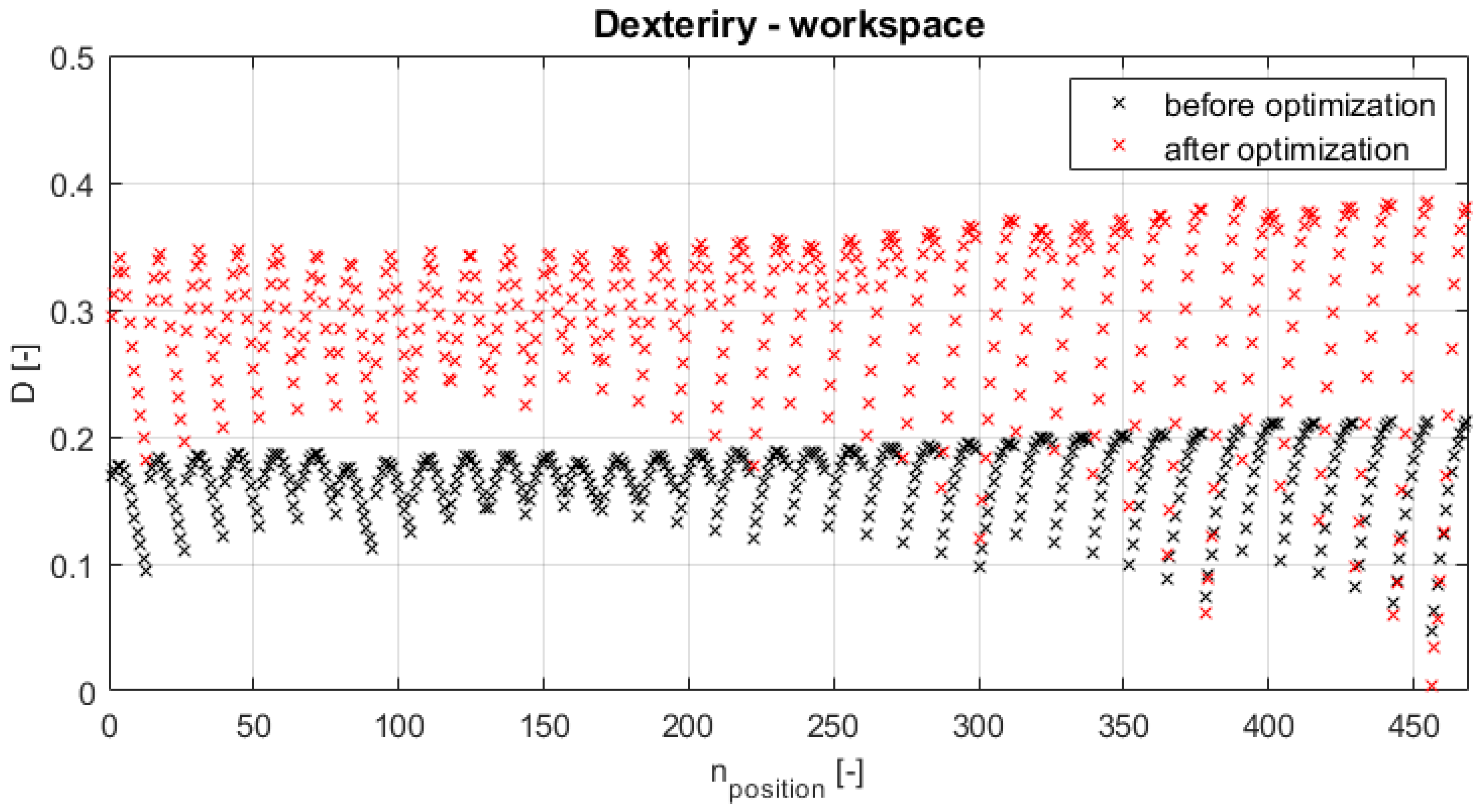
Two optimization methods are used: the local optimization algorithm (Simplex) [25] and the global constrained optimization algorithm (Genetic algorithm) (GA) [26,27]. The best optimization result is chosen in the control algorithm and is reached by the GA method. All three partial C F are improved (Table 3) and the optimized values are shown in Table 4. The optimized structure is shown in Figure 6 (the scale parameters are v 1 = 1 ,   v 2 = 1 ,   v 3 = 10 ) and its dexterity through the workspace is shown in Figure 7.

5. Control Algorithm

The “Computed Torque control” (CTC) is chosen for the manipulator control strategy. The dynamic model is linearized by inverse dynamics, and two different regulators are chosen. The cable force distribution and the determination of the Wrench matrix follow. Finally, the trajectory generation is shown.

5.1. Computed Torque Control

The selected model contains three independent coordinates β 1 , β 2 and β 3 , which are also flat outputs, and thus, y 1 = β 1 , y 2 = β 2 and y 3 = β 3 . Evidence of this is given in [28]. Furthermore, lets introduce variables y 4 = β ˙ 1 , y 5 = β ˙ 2 and y 6 = β ˙ 3 followed by y ˙ 1 = y 4 = β ˙ 1 , y ˙ 2 = y 5 = β ˙ 2 and y ˙ 3 = y 6 = β ˙ 3 . The vector υ has dimension n = 3 and its components are υ 1 = y ˙ 4 = β ¨ 1 , υ 2 = y ˙ 5 = β ¨ 2 and υ 3 = y ˙ 6 = β ¨ 3 (vector v is generally described in Equation (37)). The regulator action v is then converted by the transformation to the vector u , which also has dimension n = 3 and its form is u = [ M 1 , M 2 , M 3 ] T for the chosen planar structure. The last step is to transform u = [ M 1 , M 2 , M 3 ] T to u = [ S 1 , S 2 , S 3 , S 4 ] T . The mentioned transformation between v and u is, in this case, the inverse dynamics of the manipulator. The model can be written now in Brunovsky’s (canonical) form as follows [29]
d d t ( y 1 y 2 y 3 y 4 y 5 y 6 ) = ( 0 0 0 1 0 0 0 0 0 0 1 0 0 0 0 0 0 1 0 0 0 0 0 0 0 0 0 0 0 0 0 0 0 0 0 0 ) ( y 1 y 2 y 3 y 4 y 5 y 6 ) + ( 0 0 0 0 0 0 0 0 0 1 0 0 0 1 0 0 0 1 ) v

5.2. Inverse Dynamics

The dynamic model with control inputs can be written in the universal form [30]
M ( q ) q ¨ + C ( q ,   q ˙ ) + G ( q ) = K ( q , q ˙ ) u ,
where M ( q ) is the matrix representing the inertia forces, vector q represents generalized coordinates, u are the control inputs, C ( q ,   q ˙ ) is the vector of Coriolis and centrifugal terms, vector G ( q ) represents the gravitational forces and K ( q , q ˙ ) is the matrix characterizing the actuating forces. To express the vector u one has
u = K ( q , q ˙ ) 1 [ M ( q ) q ¨   + C ( q ,   q ˙ ) + G ( q ) ]
Since u and v = [ β ¨ 1 , β ¨ 2 , β ¨ 3 ] T = q ¨ are known, the vector v can be written in the form
q ¨ = v = M ( q ) 1 [ C ( q ,   q ˙ ) + G ( q ) ] + M ( q ) 1 K ( q , q ˙ ) u
In the next step, two DM of the manipulator are considered: (1) the DM with the moments only M M (no cables); (2) the DM with the cables only ( S ) (no moments). This leads to the expression M M = J β T S . For the considered two DM models u is
M q q ¨ f ( q , q ˙ ) = M M = J β T S = W S = u ,
where
M q = [ I 1 S 1 0 0 0 I 2 S 2 0 0 0 I 3 S 3 ] ,     q ¨ = [ β 1 ¨ , β 2 ¨ , β 3 ¨ ] T ,     f ( q , q ˙ ) = [ f q 1 f q 2 f q 3 ] .
The f q 1 , f q 2 and f q 3 are given separately
f q 1 = ( m 2 y 2 ¨ m 3 y 3 ¨ G 2 G 3 ) g 1   c o s β 1 + ( m 2 x 2 ¨ + m 3 x 3 ¨ ) g 1 s i n β 1 + ( m 1 x 1 ¨ + m 2 x 2 ¨ + m 3 x 3 ¨ ) f 1 s i n β 1 ( m 1 y 1 ¨ + m 2 y 2 ¨ + m 3 y 3 ¨ + G 1 + G 2 + G 3 ) f 1 c o s β 1
f q 2 = ( m 3 y 3 ¨ + G 3 ) g 2 c o s β 2 + ( m 3 x 3 ¨ ) g 2 s i n β 2 + ( m 2 x 2 ¨ + m 3 x 3 ¨ ) f 2 s i n β 2 ( m 2 y 2 ¨ + y 3 ¨ + G 2 + G 3 ) f 2 c o s β 2
f q 3 = ( m 3 x 3 ¨ ) f 3 s i n β 3 ( m 3 y 3 ¨ + G 3 ) f 3 c o s β 3
This determines the left side of Equation (38). The right side of the equation is equal to M M (notice that the M M is not the joint motor inputs since the absolute variables are used) if no cables are used. The right part of Equation (38) is equal to J β T S = W S for the cable-driven model and obviously J β T = W . The transposed Jacobi transfer matrix J β T is defined as follows
[ l p 1 ˙ l p 2 ˙ l p 3 ˙ l p 4 ˙ ] = J β [ β 1 ˙ β 2 ˙ β 3 ˙ ]

5.3. Wrenchian

The determination of W (Equation (47)) by expressing the right side of Equation (38) from the DM of the manipulator with cables is given below:
The first link
[ s i n γ 1 g 1 c o s β 1 c o s γ 1 g 1 s i n β 1 c o s γ 1 f 1 s i n β 1 + s i n γ 1 f 1 c o s β 1 ] S 1 = W 11 S 1 [ s i n γ 2 g 1 c o s β 1 c o s γ 2 g 1 s i n β 1 c o s γ 2 f 1 s i n β 1 + s i n γ 2 f 1 c o s β 1 ] S 2 = W 12 S 2 [ s i n γ 3 g 1 c o s β 1 c o s γ 3 g 1 s i n β 1 c o s γ 3 f 1 s i n β 1 + s i n γ 3 f 1 c o s β 1 ] S 3 = W 13 S 3 [ c o s γ 4 f 1 s i n β 1 + s i n γ 4 f 1 c o s β 1 + ( q 4 f 1 ) s i n α 4 ] S 4 = W 14 S 4
The second link
[ s i n γ 1 g 2 c o s β 2 c o s γ 1 g 2 s i n β 2 c o s γ 1 f 2 s i n β 2 + s i n γ 1 f 2 c o s β 2 ] S 1 = W 21 S 1 [ s i n γ 2 g 2 c o s β 2 c o s γ 2 g 2 s i n β 2 c o s γ 2 f 2 s i n β 2 + s i n γ 2 f 2 c o s β 2 ] S 2 = W 22 S 2 [ c o s γ 3 f 2 s i n β 2 + s i n γ 3 f 2 c o s β 2 + ( q 3 f 2 ) s i n α 3 ] S 3 = W 23 S 3 [ 0 ] S 4 = W 24 S 4
The third link
[ c o s γ 1 f 3 s i n β 3 + s i n γ 1 f 3 c o s β 3 + ( q 1 f 3 ) s i n α 1 ] S 1 = W 31 S 1 [ c o s γ 2 f 3 s i n β 3 + s i n γ 2 f 3 c o s β 3 + ( q 2 f 3 ) s i n α 2 ] S 2 = W 32 S 2 [ 0 ] S 3 = W 33 S 3 [ 0 ] S 4 = W 34 S 4
W = [ W 11 W 12 W 13 W 14 W 21 W 22 W 23 W 24 W 31 W 32 W 33 W 34 ]

5.4. Cable Force Distribution

The equivalent approach based on SVD decomposition is shown to determine the parameter λ S and force vector S .

SVD Decomposition

Firstly, the matrix W is decomposed as
W S = U D S V T S = M M ,
where U , D S and V T arise from the S V D decomposition. Matrix U and V are orthonormal with property UTU = VTV = I and D is the diagonal matrix of singular values. In the next step, Equation (48) is multiplied by U T (left side)
D V T S = U T M M .
By substitution V T S = x s v d and U T M M = b s v d in Equation (49) one has
D x s v d = b s v d .
Equation (50) in matrix form
[ d 11 0 0           0 0 d 22 0           0 0 0 d 33 0 ] [ x s v d 1 x s v d 2 x s v d 3 x s v d 4 ] = [ b s v d 1 b s v d 2 b s v d 3 ] .
From Equation (51) is obvious that
x s v d 1 = b s v d 1 d 11 ,     x s v d 2 = b s v d 1 d 33 ,     x s v d 3 = b s v d 1 d 33 ,     x s v d 4 = λ S
Now, the parameter λ S can be chosen. The forces in the cables are then
S = V x s v d = S 0 + V 4 λ S = m = 1 3 V m x s v d m + V 4 λ S
where V m is the m-th column and V 4 is the fourth column of the orthonormal matrix V and is identical to the orthonormal vector N = V 4 from Equation (5). Considering the lower limit as 0 S m i n = [ S m i n 1   , S m i n 2   , S m i n 3   , S m i n 4   ] (cables are able to transfer the tensile force only) and the upper limit as [ S m a x 1   , S m a x 2   , S m a x 3   , S m a x 4   ] = S m a x S m o t o r s , where S m o t o r s = [ S m o t o r 1 , S m o t o r 2 , S m o t o r 3 , S m o t o r 4 ] is the vector of the maximal permissible motor force (which is defined by the chosen motor), one has
0 S m i n S 0 + V 4 λ S S m a x S m o t o r s
The parameter S m i n is chosen with respect to the application. For this case, the vector S m i n is chosen identically for every cable, the value is 25   N . The vector S m a x is also chosen to be identic for each cable, the value is 700   N . Finally, the parameter λ S is computed dynamically so that the pretension on the cables is in the required limits just in the middle of this interval during the motion and at the steady-state.

5.5. Two Different Regulators

Two different regulators are implemented for the centralized control. The PI and PID regulators in cascade with feed-forward are used, and the flatness-based regulator follows [31].

5.5.1. PI and PID Cascade with Feed-Forward (FF)

The scheme is shown in Figure 8 ( Y = [ q 1 , q 2 , q 3 ] ). The tuning method is divided into two steps: (1) velocity loop tuning and (2) position loop tuning. For both cases, the Ziegler–Nichols method is used as the first approach. The FF is added extra and is tuned experimentally. The Equation of PID regulator
u ( t ) = K p ( e ( t ) + 1 T i   0 t e ( τ ) d τ + T d d e ( t ) d t )
After the first tuning, the error dynamics and stability are tested (chirp, step and impulse functions). The experimental results are as follows: feed-forward gain K = [ 1 , 1 , 1 ] T , PI regulator constants: K p = 1 and K i = 10 (identical for e q 1 , e q 2 and e q 3 ) . PID regulator constants: K p = 75 ,   K i = 200 and K d = 0.00125 for e q 1 and K p = 75 ,   K i = 200 and K d = 0.00125 for e q 2 and e q 3 .

5.5.2. Flatness Based Regulator

The control scheme is shown in Figure 9. The relation between v and regulator inputs q ¨ d e s i r e d and e (tracking error) is given as
υ i ( t ) = k 0 i · 0 t e i ( τ ) d τ + k 1 i · e i ( t ) + k 2 i · e ˙ i ( t ) + q ¨ i d e s i r e d ,     i = 1 , 2 , 3
where q ¨ d e s i r e d is the ideal dynamic model input (generated from the desired trajectory) and the rest of the right side of the equation corrects the tracking error. Coefficients k i are chosen such that the tracking error polynomial is the Hurwitz one. The Routh—Hurwitz Criterion is used to determine the coefficients. Necessary, but not sufficient, conditions for stability for a system are shown in the following equation
a 0 s m + a 1 s m 1 + + a m = 0 ,
where [31,32]:
  • All the coefficients of the equation should have the same sign
  • There should be no missing term
This method leads to the stable tracking error dynamics. The coefficients k 0 , k 1 and k 2 chosen for simulation are k 0 = 100 , k 1 = 50 and k 2 = 20 (identical for e q 1 , e q 2 and e q 3 ) .

5.6. Trajectory Generation

The trajectory generation is always performed in the manipulator workspace, where it is verified that the manipulator with the selected parameters for a simulation always has the form of matrix W, such that it allows the cables to be prestressed (singular positions are outside the workspace).
Three different trajectories are considered: Point-to-point S-line, circle and rectangle. S-line is generated as a Bezier curve fifth order. Circular and rectangular trajectories are generated purposely with velocity and acceleration step changes to verify the stability of the control algorithm.

6. Simulation Testing

The dynamic model used in the control section is changed in parameters (about 10–20% randomly) to verify the control algorithm. The constants k c a b l e and b r c a b l e are chosen as 5 × 10 5   N / m and 0.002 , respectively. The constant b c a b l e is given by these steps: the mass of arms ( m t o t a l = m 1 + m 2 + m 3 ) is divided by the number of cables, then Ω c a b l e = 4 k c a b l e / m t o t a l and b = 0.5 m t o t a l b r c a b l e Ω c a b l e (note that this is only an approximation for the purpose of simulation). The moments of inertia are, for simplicity, chosen as I i S i = m 1 l i 2 12 , i = 1 , 2 , 3 (the CoG is in l i / 2 ). The overview of the chosen parameters is shown in Table 5.
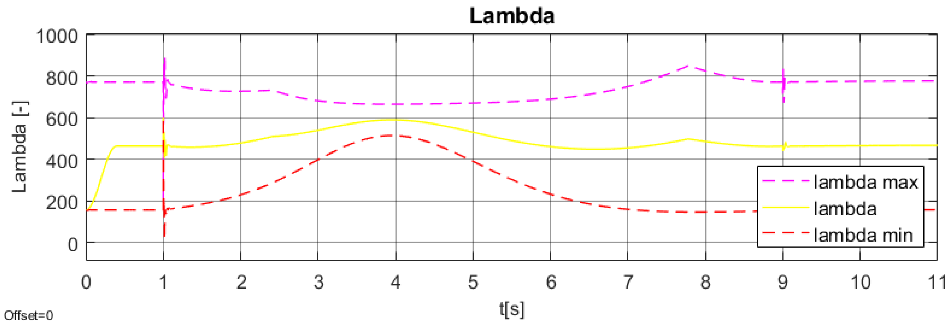
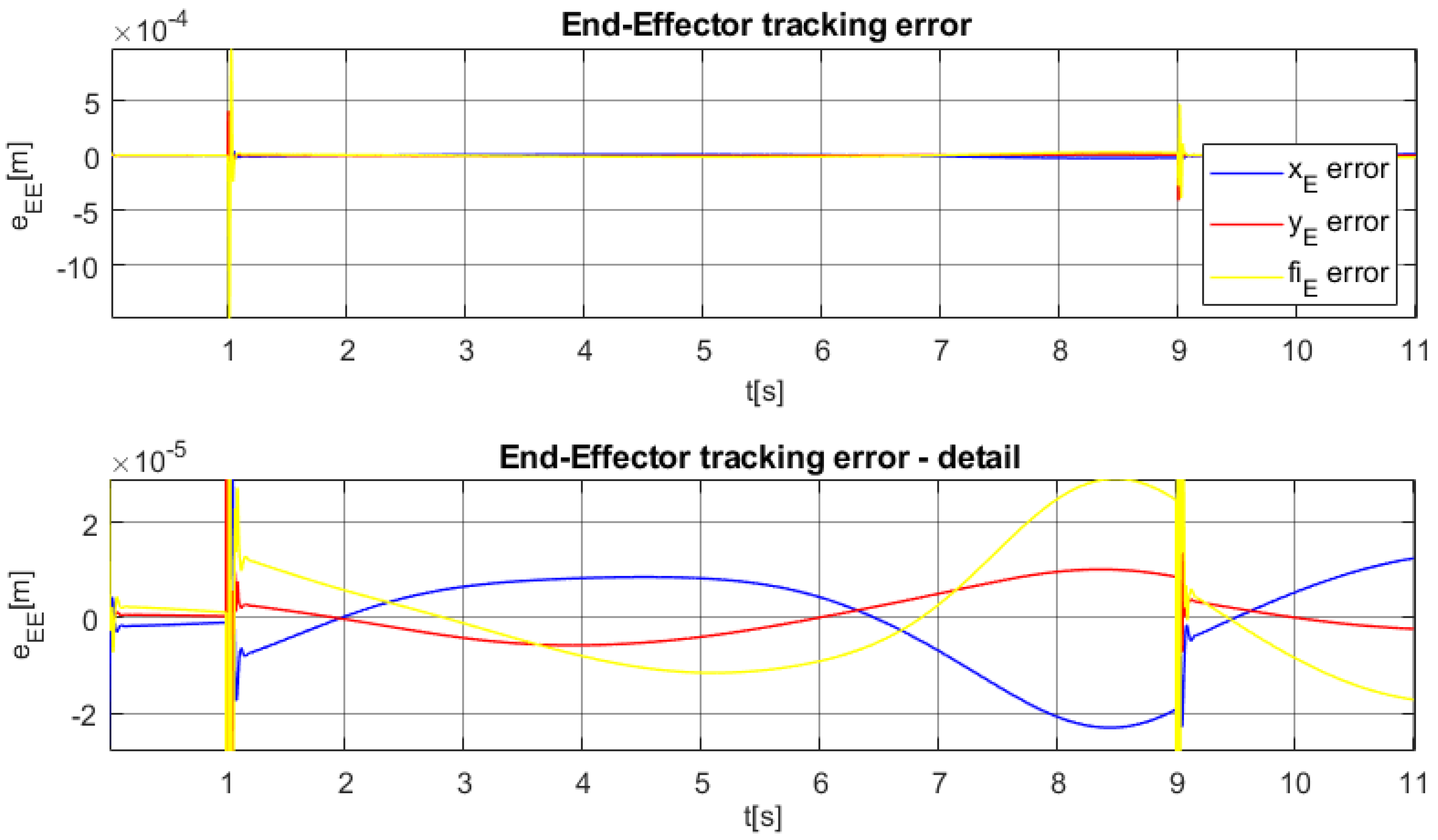
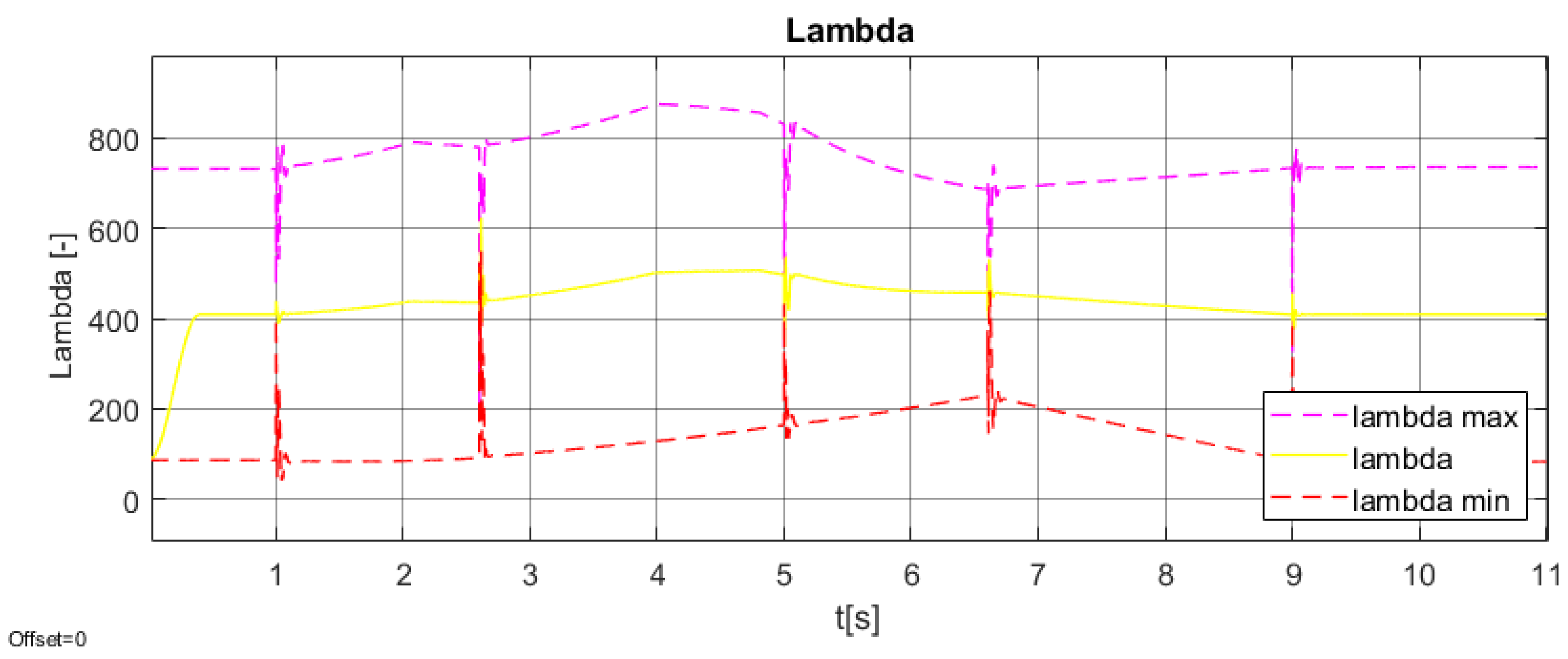
The simulation results are shown for the three considered trajectories. The figures are coupled for each trajectory: (1) Parameter λ and its boundaries and (2) end-effector tracking error. Time to prestress the cables is chosen as one s (two s for S-line trajectory). Then the interval eight s (six s for S-line trajectory) is set to execute the desired trajectory.
The S-line trajectory with a flatness-based regulator is shown in Figure 10 and Figure 11. The trajectory is smooth enough and λ is kept in the middle of boundaries with no oscillations.
The next trajectory is the circle one. The Figure 12 and Figure 13 show the simulation results using the PI and PID cascade with FF. The step changes are evident at the beginning and at the end of the executed trajectory (stability test). The λ parameter is kept in the middle of the boundaries. However, λ m a x and λ m i n are very close in the middle of the trajectory, and thus, the control algorithm is close to the limit of prestressing.
The rectangle trajectory is the last tested one. Results with the PI and PID cascade with the FF regulator are shown in Figure 14, Figure 15 and Figure 16. The regulator reaction to the step change of velocity direction is shown in Figure 16. Again, the step changes are evident in the beginning, in the end of executed trajectory and in the three middle points (corners). This shows that the regulator can stabilize the dramatic changes, which can be reduced by smooth trajectory planning.

7. Conclusions

The planar three degrees of freedom cable-driven manipulator, which is a combination of a serial kinematic chain with cable elements, is investigated and represents an intermediate stage of a targeted tensegrity structure. The dynamic model is assembled, and the optimization process, which is focused on the whole structure of the manipulator, follows. Both the local simplex and the global genetic algorithm optimization methods are chosen for the optimization, and both methods showed an improvement in the partial cost functions. Once the structure is optimized, the best result is used in a control algorithm, where two types of controllers are compared. Both controllers show very good simulation results even with significantly different model parameters used in the control algorithm. The cable elements are considered extensible, and two methods to solve the force distribution into the cables using Wrenchian are introduced and their incorporation into the dynamic model and the control algorithm are shown. The cable prestressing control follows. In the trajectory generation section, the Bezier curves’ fifth order is used as the first step. Subsequently, the circle and rectangle trajectories are purposely constructed with step changes of velocity profiles so that the stability of the whole model is tested. Finally, the model sufficiently follows the desired trajectories and cable tension is held sufficiently in the desired interval.

Author Contributions

Conceptualization, Z.Š.; methodology, J.K. and Z.Š.; software, J.K.; validation, J.K. and Z.Š; formal analysis, J.K. and Z.Š.; writing—original draft preparation, J.K.; writing—review and editing, J.K. and Z.Š; visualization, J.K. and Z.Š.; supervision, Z.Š; funding acquisition, Z.Š. All authors have read and agreed to the published version of the manuscript.

Funding

This research was funded by the Czech Science Foundation project 20-21893S “Mechatronic tensegrities for energy efficient light robots” and partly by the project SGS19/156/OHK2/3T/12 “Mechatronics and adaptronics 2019” of Czech Technical University in Prague.

Conflicts of Interest

The authors declare no conflict of interest.

References

  1. Vahrenkamp, N.; Asfour, T. Representing the robot’s workspace through constrained manipulability analysis. Auton. Robot. 2015, 38, 17–30. [Google Scholar] [CrossRef]
  2. Volech, J.; Mráz, L.; Šika, Z.; Valášek, M. Model of Flexible Robot with Deformation Detection. Procedia Eng. 2014, 96, 510–516. [Google Scholar] [CrossRef] [Green Version]
  3. Fareh, R.; Saad, M.; Saad, M. Distributed control strategy for flexible link manipulators. Robotica 2014, 33, 768–786. [Google Scholar] [CrossRef]
  4. Skelton, R.; Oliveira, M. Tensegrity Systems; Springer: Dordrecht, The Netherlands, 2009. [Google Scholar]
  5. SunSpiral, V.; Agogino, A.; Atkinson, D. Super Ball Bot-Structures for Planetery Landing and Exploration for NASA Innovation Advanced Concepts (NIAC) Program; NASA Ames Research Center: Mountain View, CA, USA, 2015. [Google Scholar]
  6. Fadeyev, D.; Zhakatayev, A.; Kuzdeuov, A.; Varol, H.A. Generalized Dynamics of Stacked Tensegrity Manipulators. IEEE Access 2019, 7, 63472–63484. [Google Scholar] [CrossRef]
  7. Aldrich, J.B.; Skelton, R.E. Backlash-free motion control of robotic manipulators driven by tensegrity motor networks. In Proceedings of the 45th IEEE Conference on Decision and Control, San Diego, CA, USA, 13–15 December 2006; pp. 2300–2306. [Google Scholar]
  8. Svatoš, P.; Šika, Z.; Valášek, M.; Zicha, J.; Bauma, V.; Rada, V. Fiber Driven Tilting Mechanism. In The Latest Methods of Construction Design; Springer: Singapore, 2016; pp. 353–357. [Google Scholar]
  9. Valášek, M.; Karásek, M. HexaSphere with Cable Actuation. In Recent Advances in Mechatronics; Springer: Singapore, 2010; pp. 239–244. [Google Scholar]
  10. Skopec, T.; Šika, Z.; Valášek, M. Calibration using adaptive model complexity for parallel and fiber-driven mechanisms. Robot. 2016, 34, 1416–1435. [Google Scholar] [CrossRef]
  11. Visentin, F.; Mishra, A.K.; Naselli, G.A.; Mazzolai, B. Simplified Sensing and Control of a Plant-Inspired Cable Driven Manipulator. In Proceedings of the 2019 2nd IEEE International Conference on Soft Robotics (RoboSoft), Seoul, Korea, 14–18 April 2019; pp. 422–427. [Google Scholar]
  12. Yeo, S.; Yang, G.; Lim, W. Design and analysis of cable-driven manipulators with variable stiffness. Mech. Mach. Theory 2013, 69, 230–244. [Google Scholar] [CrossRef]
  13. Müller, A.; Hufnagel, T. Model-based control of redundantly actuated parallel manipulators in redundant coordinates. Robot. Auton. Syst. 2012, 60, 563–571. [Google Scholar] [CrossRef]
  14. Weber, X.; Cuvillon, L.; Gangloff, J. Active vibration canceling of a cable-driven parallel robot in modal space. In Proceedings of the 2015 IEEE International Conference on Robotics and Automation (ICRA), Seattle, WA, USA, 26–30 May 2015; pp. 1599–1604. [Google Scholar]
  15. Park, K.-J. Flexible robot manipulator path design to reduce the endpoint residual vibration under torque constraints. J. Sound Vib. 2004, 275, 1051–1068. [Google Scholar] [CrossRef]
  16. Preumont, A. Mechatronics: Dynamics of Electromechanical and Piezoelectric Systems; Springer: Dordrech, The Netherlands, 2006. [Google Scholar]
  17. Mu, Z.; Liu, T.; Xu, W.; Lou, Y.; Liang, B. Dynamic feedforward control of spatial cable-driven hyper-redundant manipulatorsfor on-orbit servicing. Robotica 2019, 37, 18–38. [Google Scholar] [CrossRef]
  18. Merlet, J.-P. On the Redundancy of Cable-Driven Parallel Robots; Springer: Singapore, 2015; pp. 31–39. [Google Scholar]
  19. Merlet, J.-P. The kinematics of cable-driven parallel robots with sagging cables: Preliminary results. In Proceedings of the 2015 IEEE International Conference on Robotics and Automation (ICRA), Seattle, WA, USA, 26–30 May 2015; pp. 1593–1598. [Google Scholar]
  20. Carricato, M.; Merlet, J.-P. Stability Analysis of Underconstrained Cable-Driven Parallel Robots. IEEE Trans. Robot. 2012, 29, 288–296. [Google Scholar] [CrossRef]
  21. Gouttefarde, M.; Lamaury, J.; Reichert, C.; Bruckmann, T. A Versatile Tension Distribution Algorithm for n -DOF Parallel Robots Driven by n+2 Cables. IEEE Trans. Robot. 2015, 31, 1444–1457. [Google Scholar] [CrossRef] [Green Version]
  22. Kraus, K. Redundant Cable Manipulator. Master’s Thesis, Prague, Czech Republic, 2016. [Google Scholar]
  23. Brdička, M.; Hladík, A. Theoretical Mechanics; Academia: Prague, Czech Republic, 1987. (In Czech) [Google Scholar]
  24. Lederer, P. Theory and Optimization of Mechanical Systems II; Editorial Centre CTU: Prague, Czech Republic, 1988. (In Czech) [Google Scholar]
  25. Lederer, P. Theory and Optimization of Mechanical Systems I; Editorial Centre CTU: Prague, Czech Republic, 1987. (In Czech) [Google Scholar]
  26. Hynek, J. Genetic Algorithms and Genetic Programming; Grada Publishing: Prague, Czech Republic, 2008. (In Czech) [Google Scholar]
  27. Kramer, O. Genetic Algorithm Essentials; Springer: Cham, Switzerland, 2017; Volume 679. [Google Scholar]
  28. Elisha, D.; John, T.; Adisa, A. Flat control of industrial robotic manipulators. Robot. Auton. Syst. 2017, 87, 226–236. [Google Scholar]
  29. Rouchon, P.; Murray, M.; Matin, P. Flat Systems, Equivalence and Trajectory Generation. Available online: http://www.cds.caltech.edu/~murray/preprints/mmr03-cds.pdf (accessed on 26 November 2021).
  30. Craig, J.J. Introduction to Robotics: Mechanics and Control; Englewood Cliffs: Bergen, NJ, USA, 2005. [Google Scholar]
  31. Rigatos, G.G. Nonlinear Control and Filtering Using Differential Flatness Approaches. Stud. Syst. Decis. Control. 2015, 25, 80–82. [Google Scholar]
  32. Peña, J.M. Characterizations and stable testsfor the Routh–Hurwitz conditionsand for total positivity. Linear Algebra Its Appl. 2004, 393, 319–332. [Google Scholar] [CrossRef] [Green Version]
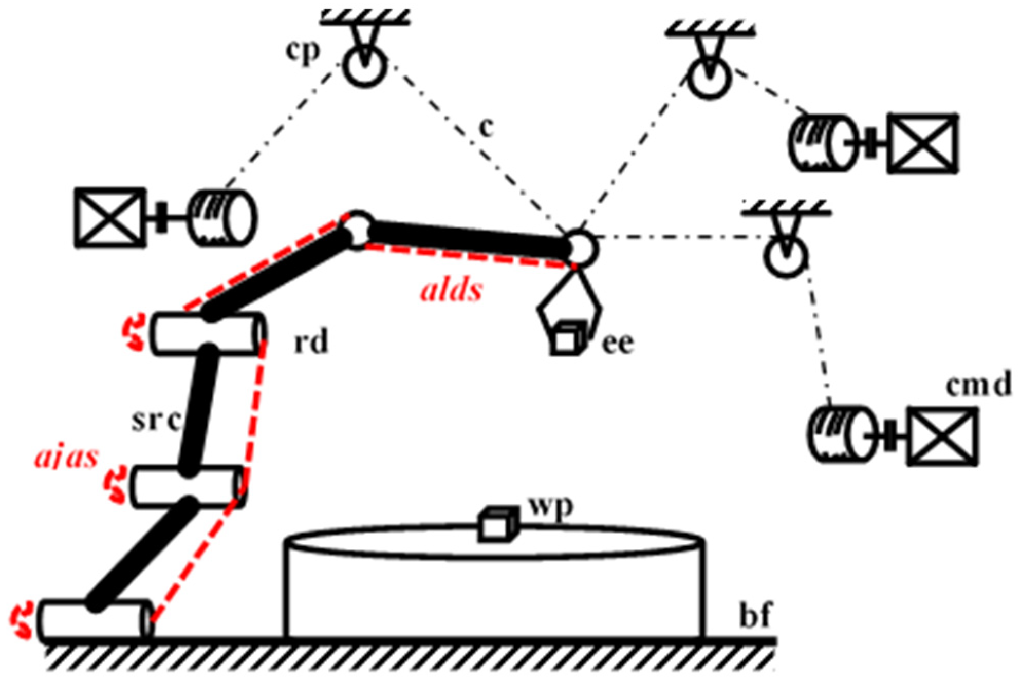
Figure 1. Basic concept of a serial manipulator with an auxiliary cable mechanism above its workspace. Legend: src—serial robot chain, wp—work piece, bf—base frame, cmd—cable mechanism drive, c—cable, ee—end effector, cp—cable pulley, rd—robot drive, optionally: alds—additional link deformation sensors, ajas—additional joint angular sensors.
Machines 09 00338 g001
Figure 2. Serial manipulator (a), cable-driven manipulator (b) and tensegrity manipulator (c).
Machines 09 00338 g002
Figure 3. Schematic description of the chosen cable-driven planar manipulator.
Machines 09 00338 g003
Figure 4. Free body diagrams of a planar-structure cable-driven manipulator.
Machines 09 00338 g004
Figure 5. (a) Moving point O i on a pulley; (b) The model of a cable with spring and damping.
Machines 09 00338 g005
Figure 6. Optimized manipulator structure—Genetic algorithm ( v 1 = 1 ,   v 2 = 1 ,   v 3 = 10 ) .
Machines 09 00338 g006
Figure 7. Dexterity of the manipulator in its chosen workspace.
Machines 09 00338 g007
Figure 8. PI and PID with feed-forward.
Machines 09 00338 g008
Figure 9. Control scheme with flatness-based regulator and cable forces transformation.
Machines 09 00338 g009
Figure 10. Parameter λ —S-line trajectory.
Machines 09 00338 g010
Figure 11. End-effector tracking error—S-line trajectory.
Machines 09 00338 g011
Figure 12. Parameter λ —circle trajectory.
Machines 09 00338 g012
Figure 13. End-effector tracking error and its detail—circle trajectory.
Machines 09 00338 g013
Figure 14. Parameter λ —rectangle trajectory.
Machines 09 00338 g014
Figure 15. End-effector tracking error—rectangle trajectory.
Machines 09 00338 g015
Figure 16. Detail of End-effector tracking error—velocity direction step change—rectangle trajectory.
Machines 09 00338 g016
Table 1. Overview of parameters b i and β i .
Index12345
b i l 1 l 2 l 3 z 2 = y E z 1 = x E
β i q 1 = β 1 q 2 = β 2 q 3 = β 3 3 / 2 π π
Table 2. The normalized cable connection distance t i .
i q i t i Interval i q i t i Interval
1 q 1 = | C Q 1 | t 1 = q 1 l 3 0.05 , 0.95 3 q 3 = | B Q 3 | t 3 = q 3 l 2 0.05 , 0.95
2 q 2 = | C Q 2 | t 2 = q 2 l 3 0.05 , 0.95 4 q 4 = | A Q 4 | t 4 = q 4 l 1 0.05 , 0.95
Table 3. Cost functions—comparison before vs. after.
C F 1 C F 2 C F 3
before 100 100 1000
after 43.7 58.8 209.8
Table 4. Optimized values of parameters.
ParameterOptim. ValueParameterOptim. ValueParameterOptim. Value
l 1 (m) 1.001 x P 2 (m) 1.507 y P 4 (m) 1.120
l 2 (m) 0.903 y P 2 (m) 0.291 t 1 (-) 0.759
l 3 (m) 0.307 x P 3 (m) 0.390 t 2 (-) 0.088
x P 1 (m) 1.415 y P 3 (m) 1.467 t 3 (-) 0.380
y P 1 (m) 1.567 x P 4 (m) 0.334 t 4 (-) 0.750
Table 5. The overview of chosen parameters for simulation testing.
ParameterValueParameterValueParameterValue
m 1 (kg) 30 I 1 S 1 (kg·m2) 4.90 k c a b l e (N/m) 5 × 10 5
m 2 (kg) 20 I 2 S 2 (kg·m2) 1.67 b r c a b l e (-) 0.002
m 3 (kg) 10 I 3 S 3 (kg·m2) 0.21 b c a b l e   (N·s/m) 5.48
Publisher’s Note: MDPI stays neutral with regard to jurisdictional claims in published maps and institutional affiliations.