
A Computationally Efficient Model Predictive Control of Six-Phase Induction Machines Based on Deadbeat Control


Abstract
:1. Introduction
2. System Model
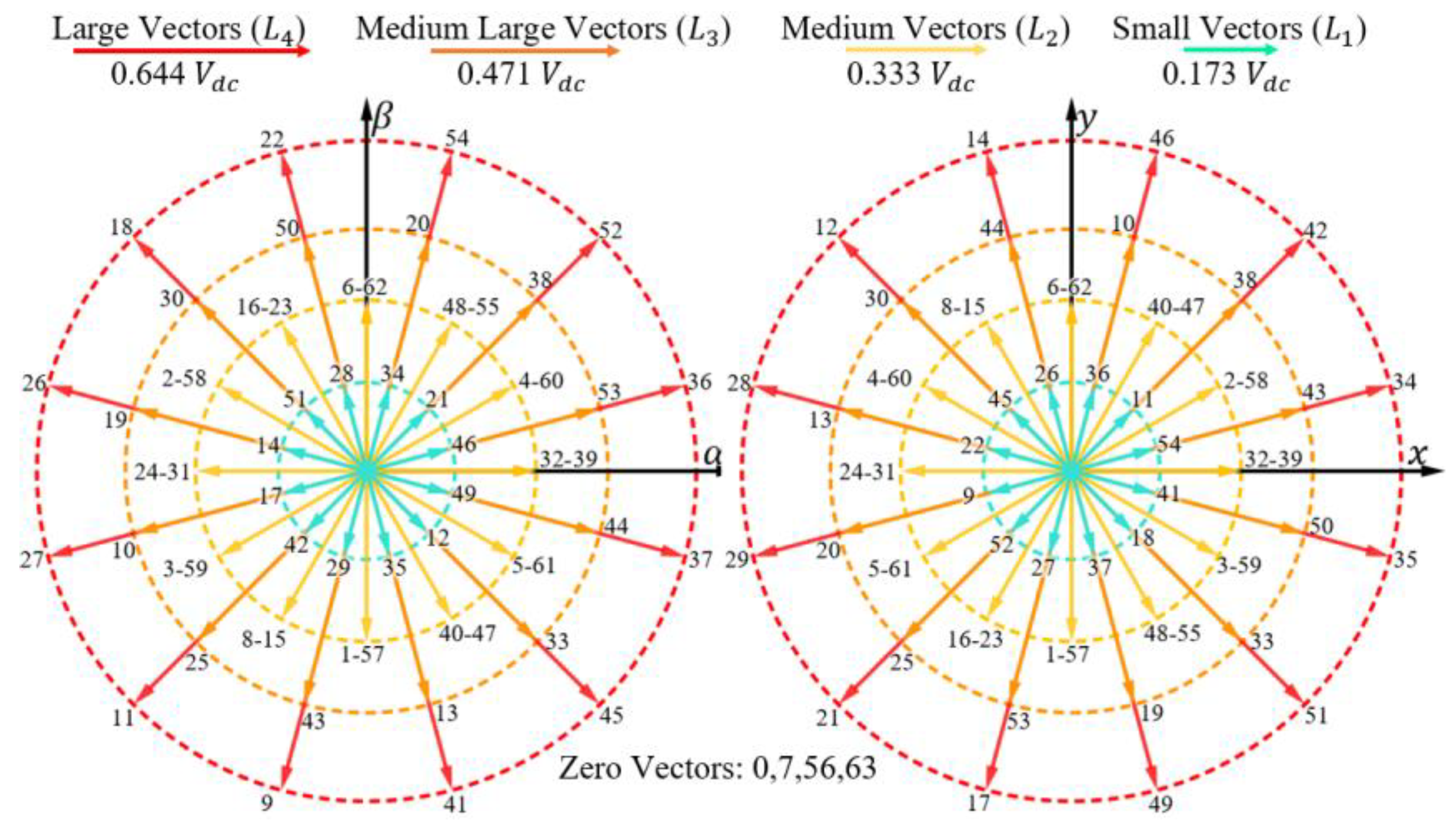
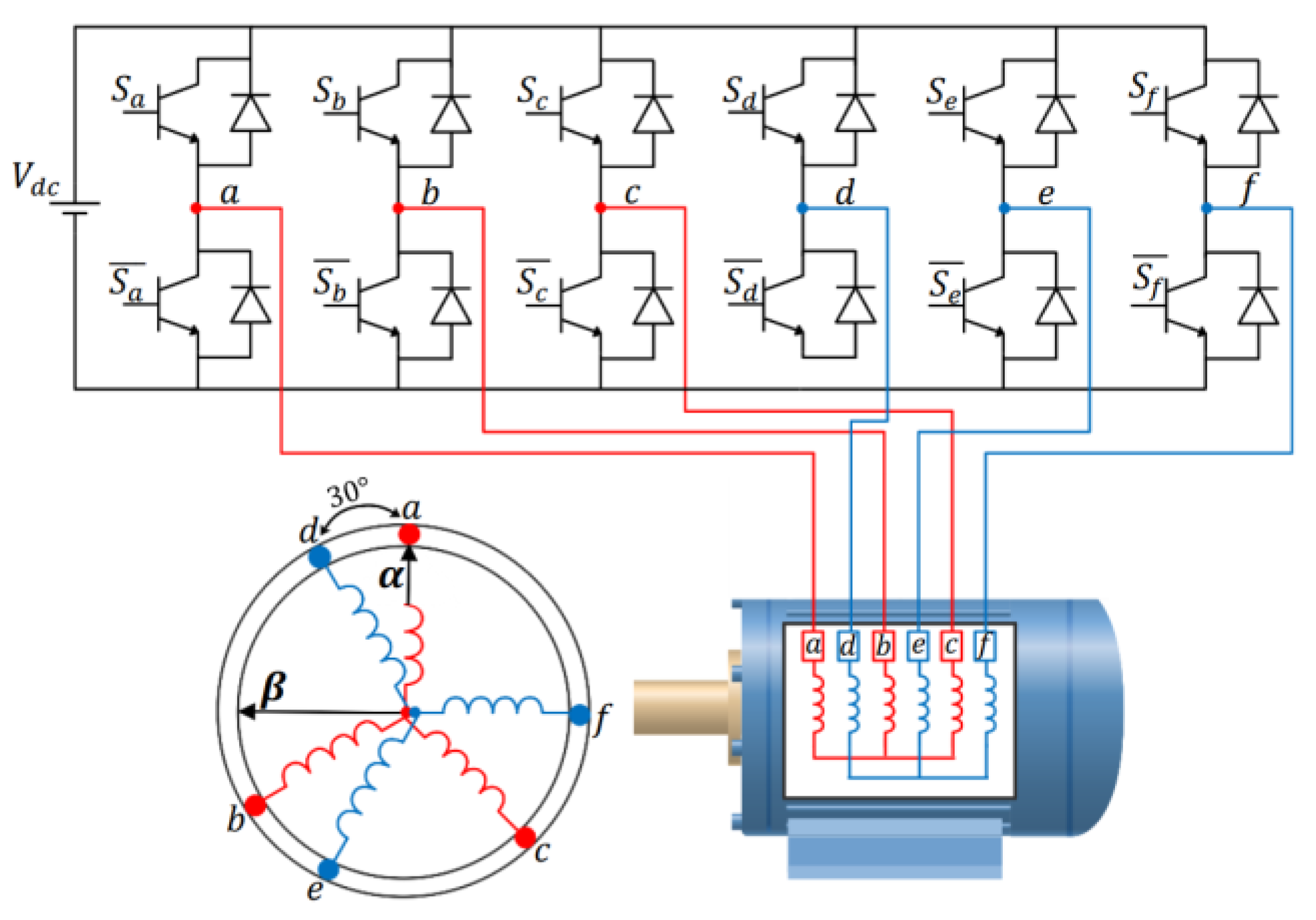
2.1. Voltage Source Inverters
2.2. Asymmetrical Six-Phase Induction Machine
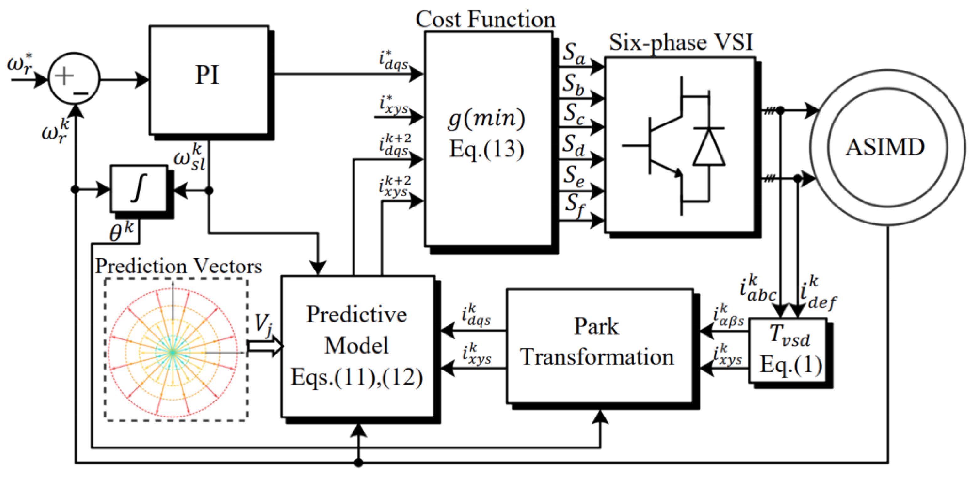
3. Classic MPCC
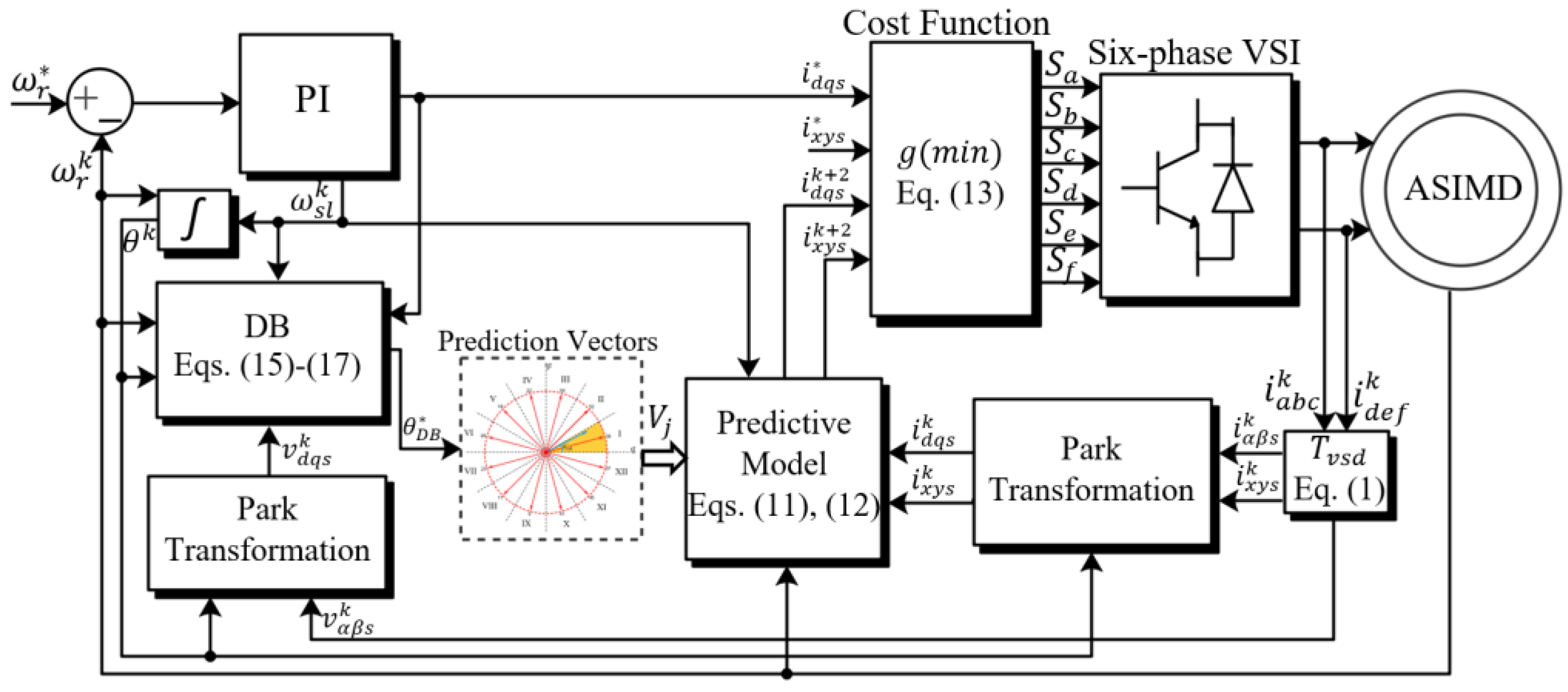
4. Proposed DB-MPCC
4.1. DB Principle
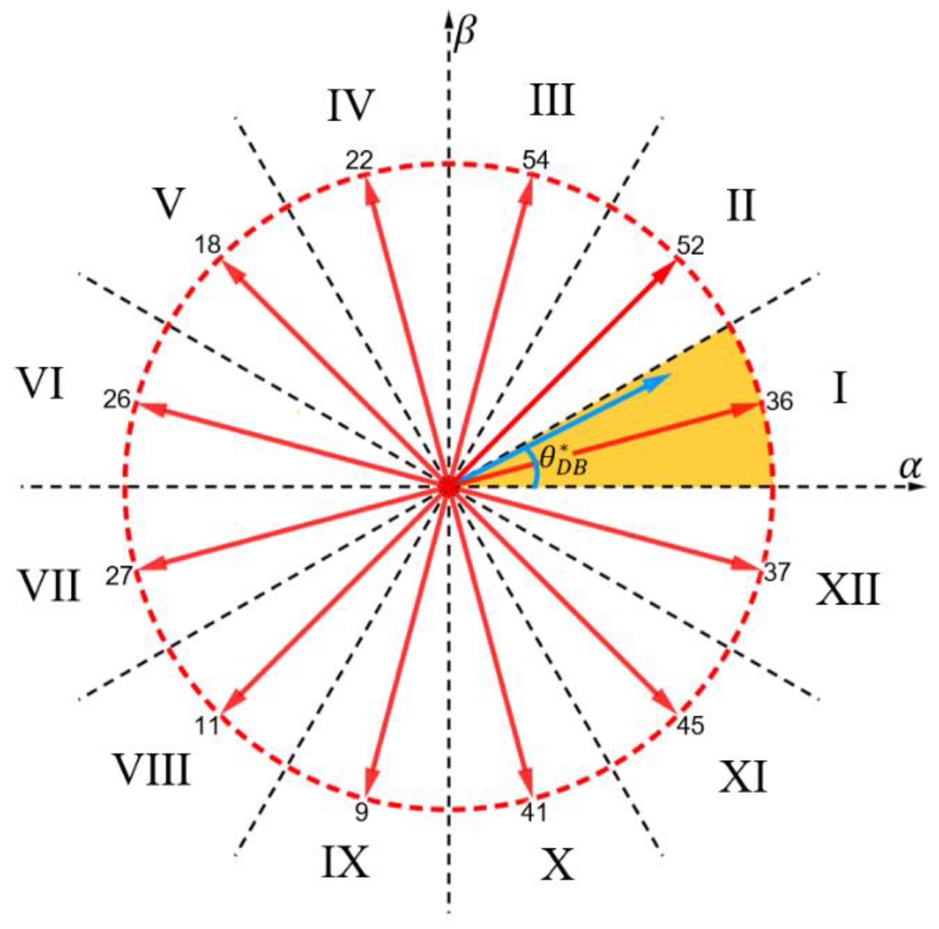
4.2. VVs Selection from DB
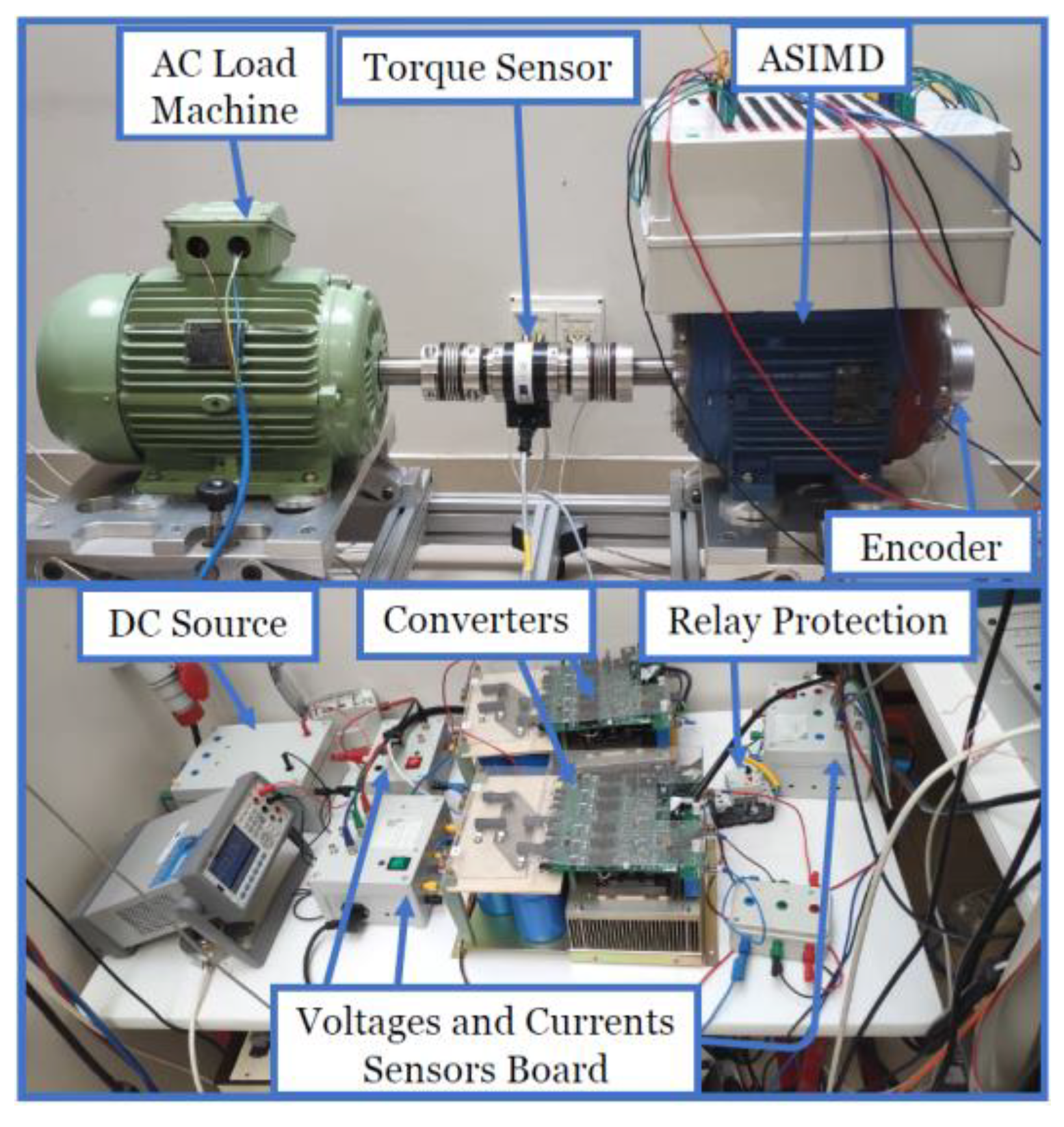
5. Experimental Results and Discussion
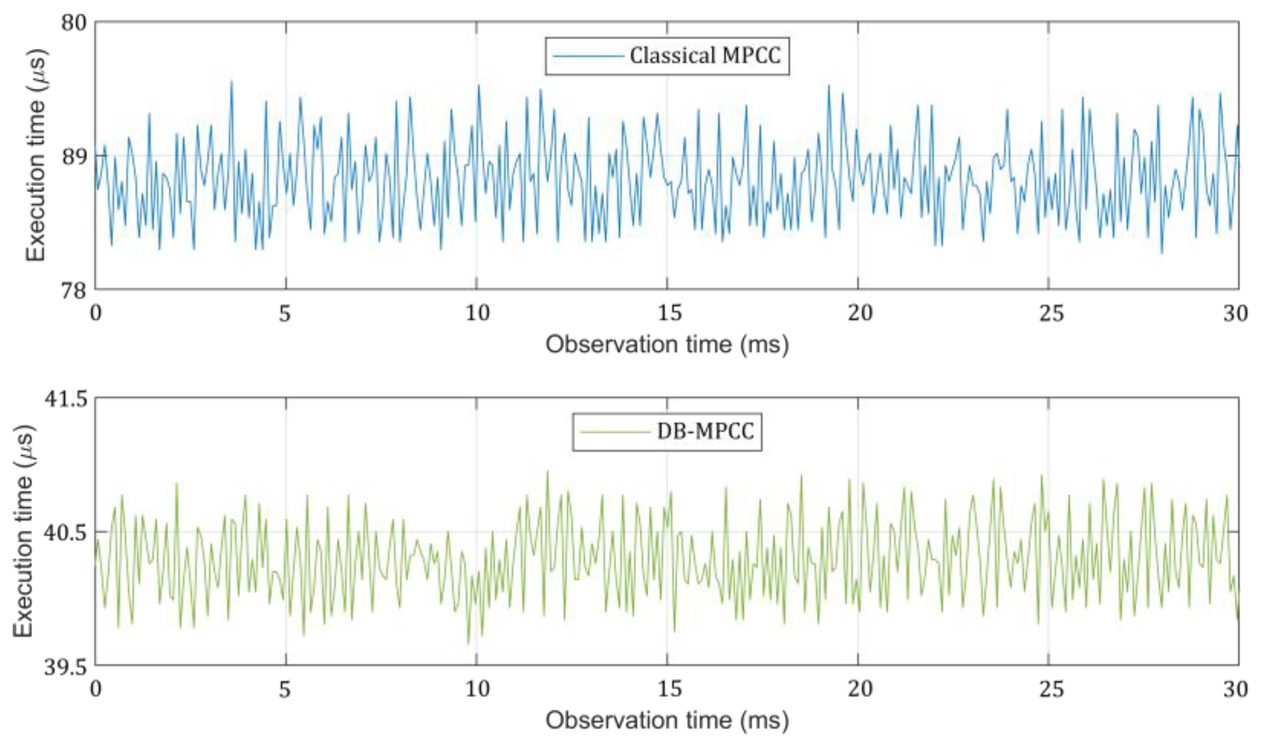
5.1. Computational Effort
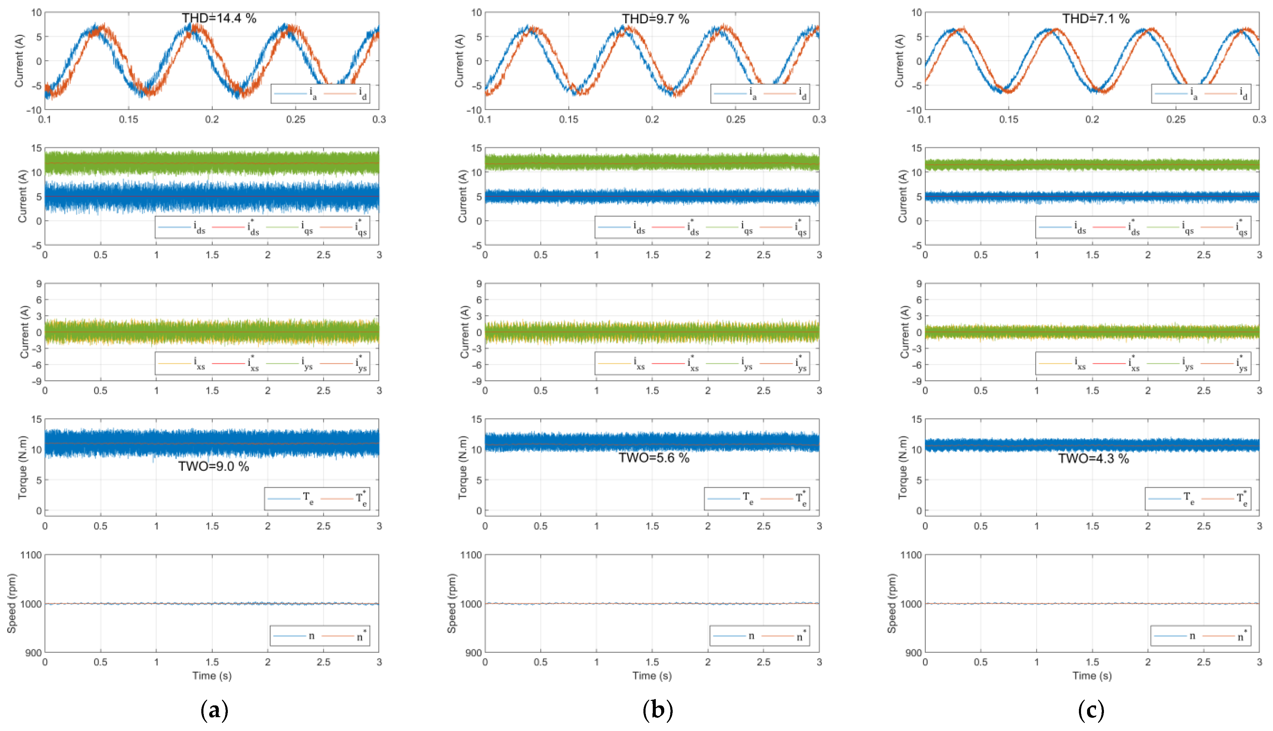
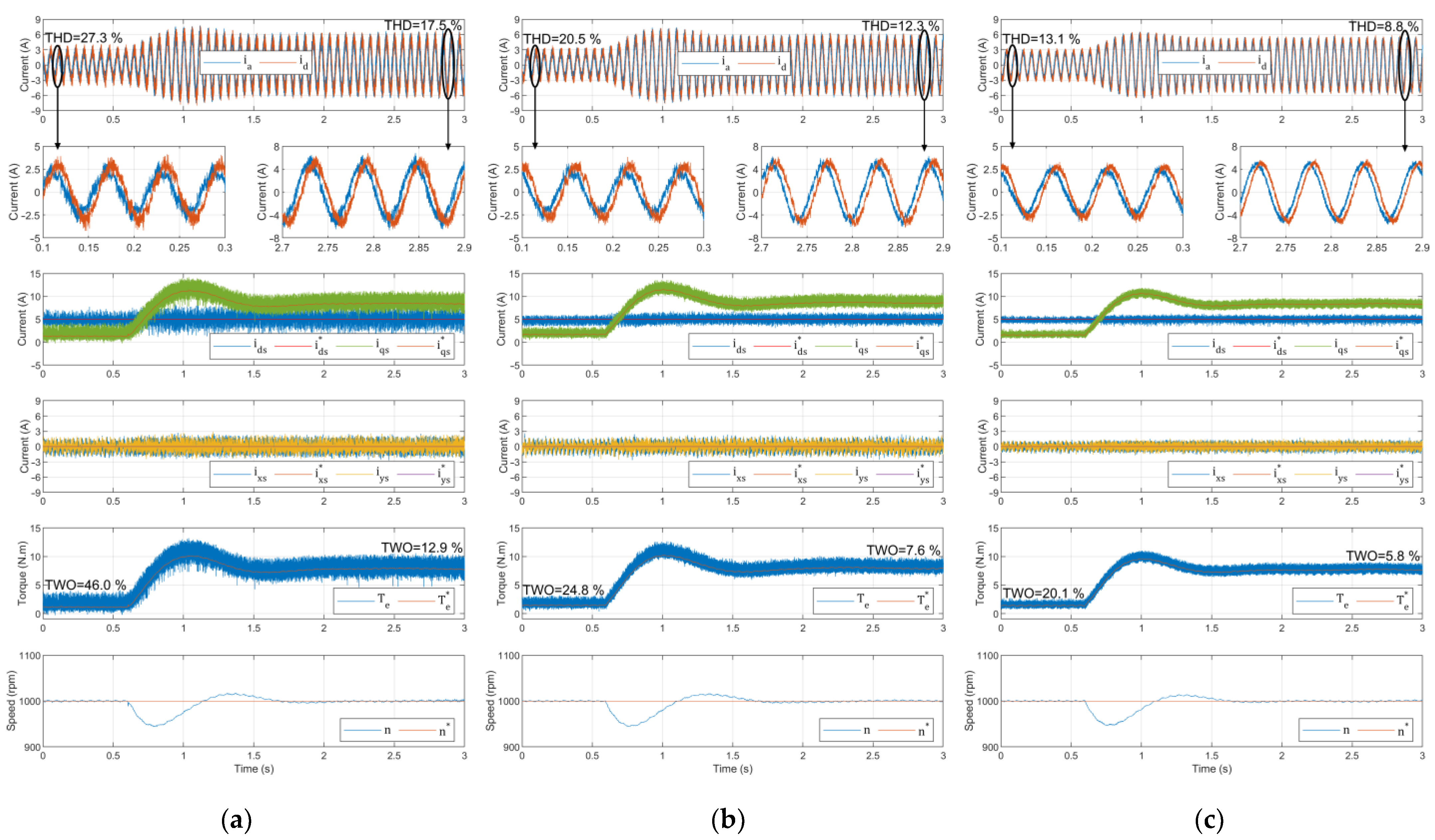
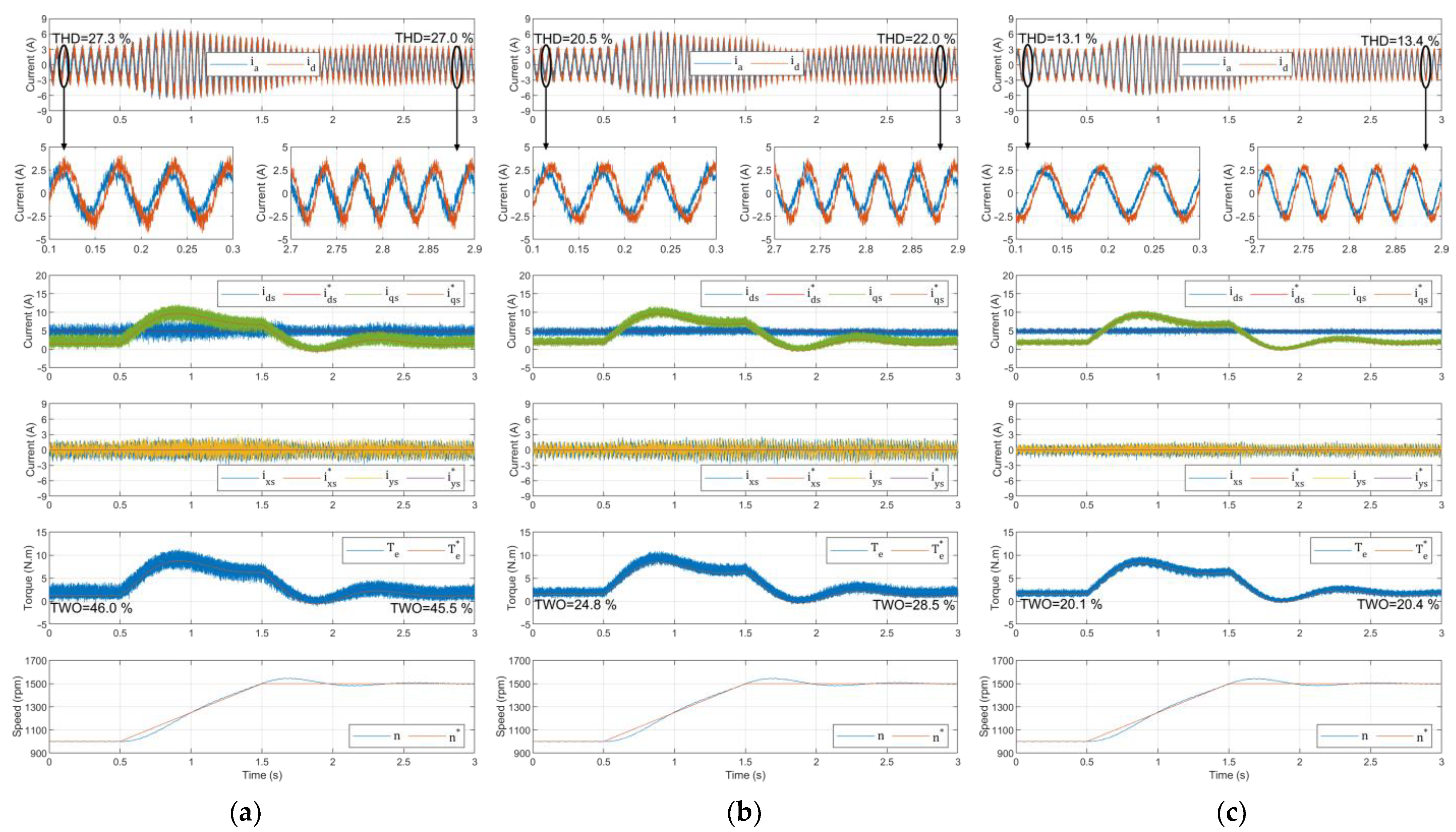
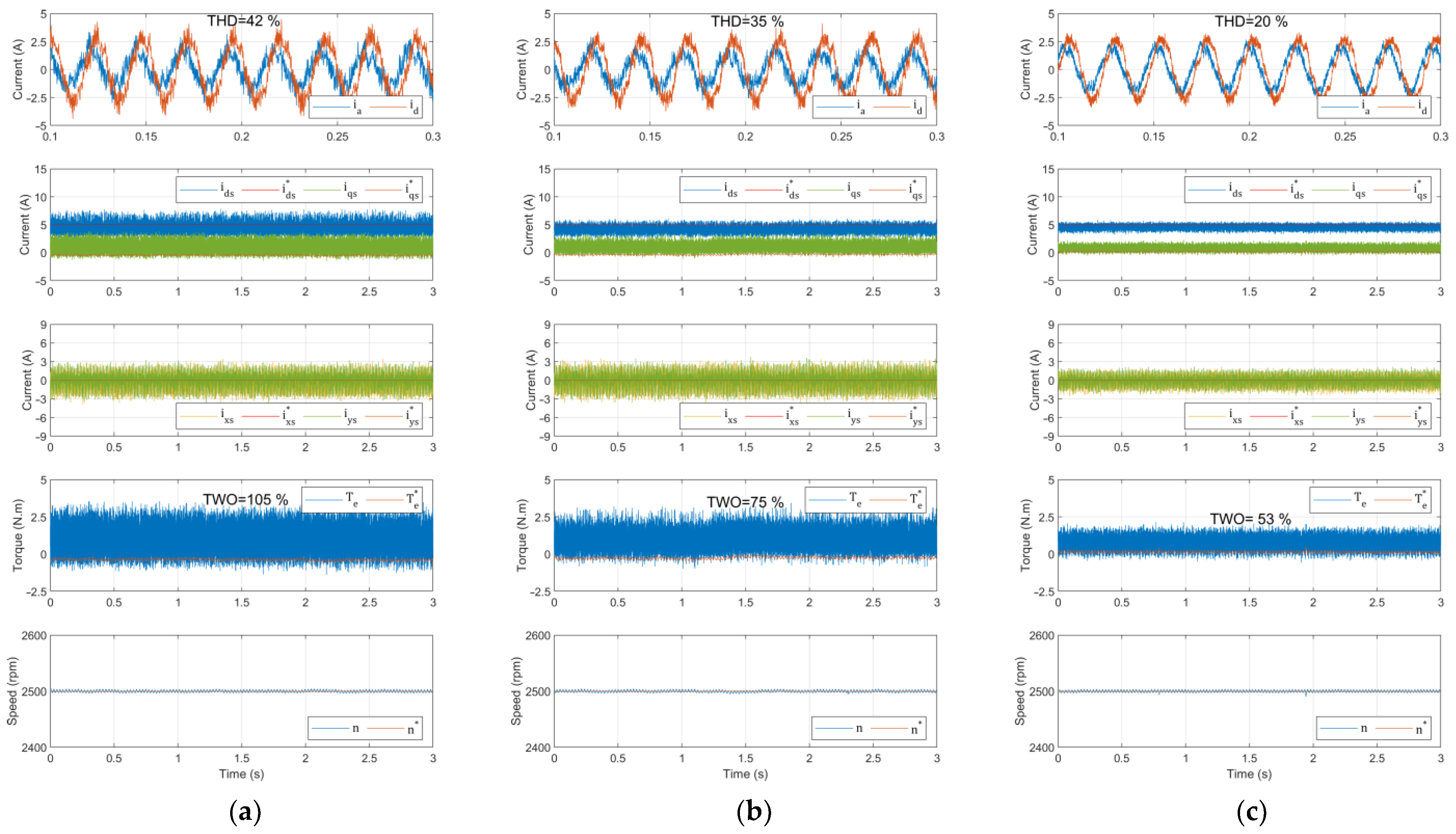
5.2. Control Performance
6. Conclusions
Author Contributions
Funding
Institutional Review Board Statement
Informed Consent Statement
Data Availability Statement
Conflicts of Interest
References
- Levi, E. Advances in Converter Control and Innovative Exploitation of Additional Degrees of Freedom for Multiphase Machines. IEEE Trans. Ind. Electron. 2016, 63, 433–448. [Google Scholar] [CrossRef] [Green Version]
- Jung, E.; Yoo, H.; Sul, S.-K.; Choi, H.-S.; Choi, Y.-Y. A Nine-Phase Permanent-Magnet Motor Drive System for an Ultrahigh-Speed Elevator. IEEE Trans. Ind. Appl. 2012, 48, 987–995. [Google Scholar] [CrossRef]
- Liu, Z.; Wu, J.; Hao, L. Coordinated and fault-tolerant control of tandem 15-phase induction motors in ship propulsion system. IET Electr. Power Appl. 2018, 12, 91–97. [Google Scholar] [CrossRef]
- Yaramasu, V.; Wu, B.; Sen, P.C.; Kouro, S.; Narimani, M. High-power wind energy conversion systems: State-of-the-art and emerging technologies. Proc. IEEE 2015, 103, 740–788. [Google Scholar] [CrossRef]
- Cortes, P.; Kaztnierkowski, M.P.; Kennel, R.M.; Quevedo, D.E.; Rodriguez, J. Predictive Control in Power Electronics and Drives. IEEE Trans. Ind. Electron. 2008, 55, 4312–4324. [Google Scholar] [CrossRef]
- Mesai-Ahmed, H.; Jlassi, I.; Cardoso, A.J.M.; Bentaallah, A. Model-Free Predictive Current Control of Synchronous Reluctance Motors Based on a Recurrent Neural Network. IEEE Trans. Ind. Electron. 2021. [Google Scholar] [CrossRef]
- De Martin, I.D.; Pasqualotto, D.; Tinazzi, F.; Zigliotto, M. Model-Free Predictive Current Control of Synchronous Reluctance Motor Drives for Pump Applications. Machines 2021, 9, 217. [Google Scholar] [CrossRef]
- Gonzalez-Prieto, A.; Gonzalez-Prieto, I.; Duran, M.J.; Aciego, J.J.; Salas-Biedma, P. Current Harmonic Mitigation Using a Multi-Vector Solution for MPC in Six-Phase Electric Drives. IEEE Access 2021, 9, 117761–117771. [Google Scholar] [CrossRef]
- Jlassi, I.; Cardoso, A.J.M. Enhanced and Computationally Efficient Model Predictive Flux and Power Control of PMSG Drives for Wind Turbine Applications. IEEE Trans. Ind. Electron. 2021, 68, 6574–6583. [Google Scholar] [CrossRef]
- Vazquez, S.; Rodriguez, J.; Rivera, M.; Franquelo, L.G.; Norambuena, M. Model Predictive Control for Power Converters and Drives: Advances and Trends. IEEE Trans. Ind. Electron. 2017, 64, 935–947. [Google Scholar] [CrossRef] [Green Version]
- Galuppini, G.; Magni, L.; Raimondo, D.M. Model predictive control of systems with deadzone and saturation. Control. Eng. Pract. 2018, 78, 56–64. [Google Scholar] [CrossRef]
- Jlassi, I.; Cardoso, A.J.M. Lookup-Table-Based Model Predictive Torque Control without Weighting Factors for PMSM Drives. In Proceedings of the IECON 2019—45th Annual Conference of the IEEE Industrial Electronics Society, Lisbon, Portugal, 14–17 October 2019; Volume 1, pp. 1165–1170. [Google Scholar]
- Guechi, E.-H.; Bouzoualegh, S.; Zennir, Y.; Blažič, S. MPC Control and LQ Optimal Control of A Two-Link Robot Arm: A Comparative Study. Machines 2018, 6, 37. [Google Scholar] [CrossRef] [Green Version]
- Jlassi, I.; Cardoso, A.J.M. Model Predictive Current Control of Synchronous Reluctance Motors, Including Saturation and Iron Losses. In Proceedings of the 2018 XIII International Conference on Electrical Machines (ICEM), Alexandroupoli, Greece, 3–6 September 2018; pp. 1598–1603. [Google Scholar]
- Kouro, S.; Cortes, P.; Vargas, R.; Ammann, U.; Rodriguez, J. Model Predictive Control—A Simple and Powerful Method to Control Power Converters. IEEE Trans. Ind. Electron. 2008, 56, 1826–1838. [Google Scholar] [CrossRef]
- Gmati, B.; Jlassi, I.; El Khil, S.K.; Cardoso, A.J.M. Open-switch fault diagnosis in voltage source inverters of PMSM drives using predictive current errors and fuzzy logic approach. IET Power Electron. 2021, 14, 1059–1072. [Google Scholar] [CrossRef]
- Laadjal, K.; Bento, F.; Jlassi, I.; Cardoso, A.J.M. Online Condition Monitoring of Electrolytic Capacitors in DC-DC Interleaved Boost Converters, Adopting a Model-Free Predictive Controller. In Proceedings of the 2021 IEEE 15th International Conference on Compatibility, Power Electronics and Power Engineering (CPE-POWERENG), Florence, Italy, 14–16 July 2021; pp. 1–6. [Google Scholar]
- Chai, M.; Gorla, N.B.Y.; Panda, S.K. Fault Detection and Localization for Cascaded H-Bridge Multilevel Converter With Model Predictive Control. IEEE Trans. Power Electron. 2020, 35, 10109–10120. [Google Scholar] [CrossRef]
- Zhou, D.; Yang, S.; Tang, Y. A Voltage-Based Open-Circuit Fault Detection and Isolation Approach for Modular Multilevel Converters with Model-Predictive Control. IEEE Trans. Power Electron. 2018, 33, 9866–9874. [Google Scholar] [CrossRef]
- Jlassi, I.; Cardoso, A.J.M. Open-circuit fault-tolerant operation of permanent magnet synchronous generator drives for wind turbine systems using a computationally efficient model predictive current control. IET Electr. Power Appl. 2021, 15, 837–846. [Google Scholar] [CrossRef]
- Jlassi, I.; Cardoso, A.J.M. Fault-Tolerant Back-to-Back Converter for Direct-Drive PMSG Wind Turbines Using Direct Torque and Power Control Techniques. IEEE Trans. Power Electron. 2019, 34, 11215–11227. [Google Scholar] [CrossRef]
- Martín, C.; Bermúdez, M.; Barrero, F.; Arahal, M.R.; Kestelyn, X.; Durán, M.J. Sensitivity of predictive controllers to parameter variation in five-phase induction motor drives. Control. Eng. Pract. 2017, 68, 23–31. [Google Scholar] [CrossRef] [Green Version]
- Barrero, F.; Arahal, M.R.; Gregor, R.; Toral, S.; Duran, M.J. A Proof of Concept Study of Predictive Current Control for VSI-Driven Asymmetrical Dual Three-Phase AC Machines. IEEE Trans. Ind. Electron. 2009, 56, 1937–1954. [Google Scholar] [CrossRef]
- Gonzalez-Prieto, I.; Duran, M.J.; Aciego, J.J.; Martin, C.; Barrero, F. Model Predictive Control of Six-Phase Induction Motor Drives Using Virtual Voltage Vectors. IEEE Trans. Ind. Electron. 2018, 65, 27–37. [Google Scholar] [CrossRef]
- Aciego, J.J.; Prieto, I.G.; Duran, M.J. Model Predictive Control of Six-Phase Induction Motor Drives Using Two Virtual Voltage Vectors. IEEE J. Emerg. Sel. Top. Power Electron. 2018, 7, 321–330. [Google Scholar] [CrossRef]
- Zhang, Y.; Xu, D.; Liu, J.; Gao, S.; Xu, W. Performance Improvement of Model-Predictive Current Control of Permanent Magnet Synchronous Motor Drives. IEEE Trans. Ind. Appl. 2017, 53, 3683–3695. [Google Scholar] [CrossRef]
- Xie, W.; Wang, X.; Wang, F.; Xu, W.; Kennel, R.M.; Gerling, D.; Lorenz, R.D. Finite-Control-Set Model Predictive Torque Control with a Deadbeat Solution for PMSM Drives. IEEE Trans. Ind. Electron. 2015, 62, 5402–5410. [Google Scholar] [CrossRef]
- Zhang, X.; Hou, B. Double Vectors Model Predictive Torque Control without Weighting Factor Based on Voltage Tracking Error. IEEE Trans. Power Electron. 2018, 33, 2368–2380. [Google Scholar] [CrossRef]
- Luo, Y.; Liu, C. Elimination of Harmonic Currents Using a Reference Voltage Vector Based-Model Predictive Control for a Six-Phase PMSM Motor. IEEE Trans. Power Electron. 2019, 34, 6960–6972. [Google Scholar] [CrossRef]
- Luo, Y.; Liu, C. Model Predictive Control for a Six-Phase PMSM Motor with a Reduced-Dimension Cost Function. IEEE Trans. Ind. Electron. 2019, 67, 969–979. [Google Scholar] [CrossRef]
- Levi, E. Multiphase Electric Machines for Variable-Speed Applications. IEEE Trans. Ind. Electron. 2008, 55, 1893–1909. [Google Scholar] [CrossRef]
- Singh, G.K.; Nam, K.; Lim, S.K. A Simple Indirect Field-Oriented Control Scheme for Multiphase Induction Machine. IEEE Trans. Ind. Electron. 2005, 52, 1177–1184. [Google Scholar] [CrossRef]
- Cortes, P.; Rodriguez, J.; Silva, C.; Flores, A. Delay Compensation in Model Predictive Current Control of a Three-Phase Inverter. IEEE Trans. Ind. Electron. 2012, 59, 1323–1325. [Google Scholar] [CrossRef]
- Cortes, P.; Kouro, S.; La Rocca, B.; Vargas, R.; Rodriguez, J.; Leon, J.I.; Vazquez, S.; Franquelo, L.G. Guidelines for weighting factors design in Model Predictive Control of power converters and drives. In Proceedings of the IEEE International Confer-ence on Industrial Technology, Churchill, VIC, Australia, 10–13 February 2009; pp. 1–7. [Google Scholar] [CrossRef]
- dSPACE GmbH. Available online: https://www.dspace.com/en/ltd/home/support/kb/faqs/faq023.cfm (accessed on 1 October 2021).
- IEEE Recommended Practices and Requirements for Harmonic Control in Electrical Power Systems. Available online: https://d1wqtxts1xzle7.cloudfront.net/44174443/IEEE519-with-cover-page-v2.pdf?Expires=1637657090&Signature=Mb-zHm2QNGFJ1IXS2lqWhZa6qbVEtyAFXrnXtgKdhtS0Cd4HEBaUW8BJn-TV6eibK4FYtdtd8maEVfO616Kjyh1HGzGDVk2lXlCvP2gPKrVm9TNyFjO~D~N2ik~zJ5jHvy89trfv~MS3s~FcjFFmopGd5xTyu9udcHlMn6-JL6V9nt1ILihxp5~UTpNbaBQfe7vyG8OCQSew6YfhgzGD7q1m21XCh8wiXt5MgHyKTushjk8aTe5qy7ohQR5wlob9nQjyFu3KGNGxsRH7sow1eV95WHae9bWiCTicNT4nIobDyrvw3j-xEjV7I0oUGFsS3LgrZ-uSIpNam86v4ca1hw__&Key-Pair-Id=APKAJLOHF5GGSLRBV4ZA (accessed on 1 October 2021).


| Regions | Selection of the Corresponding Set of VVs |
|---|---|
| Parameters | Values |
|---|---|
| DC voltage Vdc (V) | 300 |
| Motor-rated power (kW) | 6 |
| Rated speed n (rpm) | 2930 |
| Rated torque Te (Nm) | 19 |
| Stator resistance Rs (Ω) | 1.87 |
| Stator leakage inductance Lls (H) | 1.48 × 10⁻² |
| Rotor resistance Rr (Ω) | 0.499 |
| Rotor leakage inductance Llr (H) | 1.48 × 10⁻² |
| Mutual Inductance Lm (H) | 0.199 |
| Rotor inertia J (Kg-m2) | 2.43 × 10⁻² |
| Coefficient of viscous friction B (Nm/(rad/s)) | 9.0 × 10⁻⁴ |
| No. of pole pairs (P) | 1 |
| Type of Control | Numbers of VVs | Execution Time (μs) | Sampling Time (μs) |
|---|---|---|---|
| Classical MPCC | 13 | 78.82 | 90 |
| DB-MPCC | 4 | 40.39 | 50 |
Publisher’s Note: MDPI stays neutral with regard to jurisdictional claims in published maps and institutional affiliations. |
© 2021 by the authors. Licensee MDPI, Basel, Switzerland. This article is an open access article distributed under the terms and conditions of the Creative Commons Attribution (CC BY) license (https://creativecommons.org/licenses/by/4.0/).
Share and Cite
Serra, J.; Jlassi, I.; Cardoso, A.J.M. A Computationally Efficient Model Predictive Control of Six-Phase Induction Machines Based on Deadbeat Control. Machines 2021, 9, 306. https://doi.org/10.3390/machines9120306
Serra J, Jlassi I, Cardoso AJM. A Computationally Efficient Model Predictive Control of Six-Phase Induction Machines Based on Deadbeat Control. Machines. 2021; 9(12):306. https://doi.org/10.3390/machines9120306
Chicago/Turabian StyleSerra, João, Imed Jlassi, and Antonio J. Marques Cardoso. 2021. "A Computationally Efficient Model Predictive Control of Six-Phase Induction Machines Based on Deadbeat Control" Machines 9, no. 12: 306. https://doi.org/10.3390/machines9120306
APA StyleSerra, J., Jlassi, I., & Cardoso, A. J. M. (2021). A Computationally Efficient Model Predictive Control of Six-Phase Induction Machines Based on Deadbeat Control. Machines, 9(12), 306. https://doi.org/10.3390/machines9120306