Abstract
Muscle weakness is the primary impairment causing mobility difficulty among stroke survivors. Millions of people are unable to live normally because of mobility difficulty every year. Strength training is an effective method to improve lower extremity ability but is limited by the shortage of medical staff. Thus, this paper proposes a robot-assisted active training (RAAT) by an adaptive admittance control scheme with virtual reality interaction (AACVRI). AACVRI consists of a stiffness variable admittance controller, an adaptive controller, and virtual reality (VR) interactions. In order to provide human-robot reality interactions corresponding to virtual scenes, an admittance control law with variable stiffness term was developed to define the mechanics property of the end effector. The adaptive controller improves tracking performances by compensating interaction forces and dynamics model deviations. A virtual training environment including action following, event feedback, and competition mechanism is utilized for improving boring training experience and engaging users to maintain active state in cycling training. To verify controller performances and the feasibility of RAAT, experiments were conducted with eight subjects. Admittance control provides desired variable interactions along the trajectory. The robot responds to different virtual events by changing admittance parameters according to trigger feedbacks. Adaptive control ensures tracking errors at a low level. Subjects were maintained in active state during this strength training. Their physiological signals significantly increased, and interaction forces were at a high level. RAAT is a feasible approach for lower limb strength training, and users can independently complete high-quality active strength training under RAAT.
1. Introduction
There are nearly 10 million new incident stroke cases every year in the world [1,2]. As a leading cause of mortality and disability worldwide, stroke seriously influences survivors’ quality of life. Furthermore, the treatment and caring economic costs are substantial for stroke survivors’ families. Physical therapy is widely recognized as an effective method to promote, maintain, or restore the physical and physiological well-being; the research shows that the intensive repetitive task-oriented and task-specific trainings perform well in all post-stroke phases [3]. Patients practice context-specific motor tasks and can receive feedback in task-specific training; there is much evidence suggesting that the task-specific training should be added in neurological disorder therapy [4]. The feasibility of the task-specific training has been proven in clinical practice, and its effect can also transfer to other functional motor tasks not directly practiced in therapy [5,6], whereas the mounting shortage of therapists and caregivers would become a serious problem in the near future [7]. Rehabilitation robots can effectively deliver task-specific training, which are developed as an alternative solution to meet the great potential demand for rehabilitation therapy. In recent years, the clinical effect of robot-assisted therapy has been validated by many researchers [8,9,10].
Muscle weakness has been confirmed as the primary impairment which affects walking after stroke [11,12]. Muscle and its efferent pathway can both be affected by stroke. Indeed, a recent study supports that even the muscle strength on the unaffected side of hemiplegic post-stroke patients becomes weaker compared to the normal standard [13]. Other evidence shows that the strength on the unaffected side is independent to the functional improvement during short-term rehabilitation [14]. This means that muscle exercise might put more emphases on preventing the loss of muscle strength. Resistance training, a common method for strength training, has been used successfully for improving lower extremity ability (e.g., muscle strength, stride, and gait velocity) [15,16,17]; it is also utilized in cerebral palsy and spinal cord injury [18,19]. Generally, active training is referred to the training function of rehabilitation devices, which can provide assistance/resistance for strength training [20,21,22,23]. Although some current rehabilitation devices can perform active training to enhance muscle strength of patients, little attention is paid to training quality and user’s engagement in robot-assisted strength training.
Virtual reality (VR) technology provides the capability of creating a virtual environment and allowing users to receive sense (e.g., visual and auditory) feedbacks [24]. VR has been widely applied in rehabilitation [25,26]. Research shows that VR can be a beneficial environment for rehabilitation [27], and relevant health games are promising tools for rehabilitation [28]. Further, VR technology has been proven to improve motivation and engagement [29]. Chul Gyu Song et al. developed a training system combining VR technology and an unfixed bicycle to improve postural balance ability [30]. Axles of the bicycle are supported by four spring structures, and the bicycle can be tilted to cooperate virtual track scenes during the training. Handlebars can be turned freely to change the moving direction in the virtual scenes. Balance and cycling abilities have been improved after the cycling training by this device. Cycling exercise is an effective approach to improve the lower extremity motor function of stroke patients [31]. Cycling training is also a benefit to pulmonary rehabilitation, cortical plasticity, and cord injury [32,33,34]. However, this bicycle device is not suitable to the patient in early stages of rehabilitation. It is difficult for patients with mobile difficulties to climb the elevated bike. The approach in this paper is to allow earlier stage patients to take cycling strength training in a sitting posture and engage them with VR technology. However, the main problem to be solved is how to control the robot to perform desired force interaction corresponding to virtual scenes.
Admittance controller is a model-based control whose input and output are force signals and motion signals, respectively. For series robots, it is convenient to acquire force information from the end effector sensor. Besides that, it can build the relationship between robot motions and interaction forces without additional joint force sensors. Thus, admittance control is widely used in robot force control. These controllers can transform forces into desired accelerations, velocities, and positions based on preset parameters of the admittance model [35,36,37]. An admittance controller which can transform the interaction torque error into an admitted trajectory is developed, and it is applied on a functional electrical stimulation tricycle with one degree of freedom (DOF) [38]. For multilink robots, most of admittance controllers eventually generate an additional motion (with respect to the desired effector trajectory without forces) from interaction forces. The robot will perform passive compliance and elasticity in a limit range. They have been applied in human-robot interaction, training safety enhancement, active training, and inertia compensation [39,40,41,42]. Unlike these, it is a meaningful attempt that utilizes the output of a variable stiffness admittance model as task motions to obtain desired human-robot interaction in strength training.
The admittance controller generally combines with a position controller (e.g., proportional differential control, sliding mode control, or robust control) to track output position commands. Since dynamics model parameters of this robot will be changed when adjusting the device to suit different leg length of users, we utilize an adaptive controller for compensating dynamics variations and interaction forces in this research. The main idea of adaptive control theory is changing control parameters by designing adaptive law and stabilizing the system in uncertain states [43,44,45]. Apart from robot system control, adaptive control has been investigated in soft actuators, automated driving, and microgrippers [46,47,48].
In this paper, a robot-assisted active training (RAAT) by an adaptive admittance control scheme with virtual reality interaction (AACVRI) based on a lower limb rehabilitation robot called LLR-II (Figure 1) is developed. This active training is designed for motivating users to actively complete strength training task by themselves. RAAT provides a task-specific cycling strength training which can cooperate patient to complete active exercise. To encourage users during the cycling training, a virtual scene of the bicycle competition is developed using Unity 3D. The LLR-II can respond to different virtual events (i.e., uphill, downhill, or muddy road) by a variable admittance controller. An admittance control law with variable stiffness term is proposed to define the mechanics property of the end effector, which is utilized for providing human-robot reality interactions corresponding to virtual scenes. The effector moves as a virtual bike pedal and changing admittance parameters can perform virtual interactions or switch training difficulty. In order to deal with the variability of controlled system caused by dynamics parameter uncertainty, device adjustment and interaction force at the same time, so the control scheme includes an adaptive controller which can compensate the parameter variations of the dynamics model. Finally, controller performances were demonstrated in experiments. The feasibility of RAAT was verified by recording physiological signal and interaction force changes of eight subjects during the strength training.
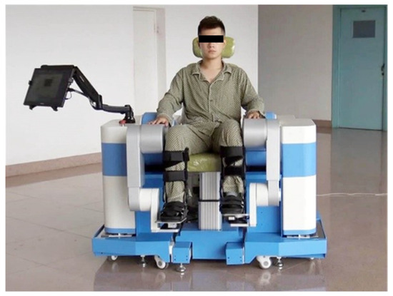
Figure 1.
LLR-II consists of two symmetrical training modules (the right one includes a touch display screen and an emergency stop button), a seat module (which can adjust high and back), and an electric control cabinet (behind the seat). Each part of LLR-II can be assembled together by linking their underframes. The width between two training modules can be adjusted, and the moveable seat can move out and transfer users to the training position.
2. Materials
The LLR-II is developed to provide sitting/lying lower limb rehabilitation training, and the training mode is sitting training posture in this research. The mechanical leg (Figure 2), which works in sagittal plane, of the training module is a series mechanism with three DOF. The drive train of joints mainly consists of flange structures; details have been introduced in other paper of our team [49].
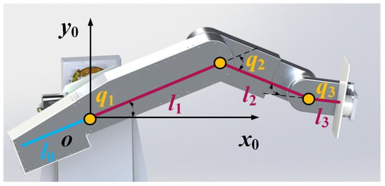
Figure 2.
The mechanical leg has three joints which correspond to hip, knee, and ankle joints, respectively (q1, q2, and q3 represent the joint variables). Each joint equips with an angular transducer. A six-axis force sensor is assembled under the end pedal. The length between two adjacent joints (i.e., l1 or l2) can be adjusted by the linear actuator inside of the mechanical leg, so this device can adapt to people with different heights. The global frame o-x0y0 is located on the first joint. The blue line represents the counterweight part, and its gravity lever arm depends on the position of the first joint (i.e., the proportion of length l0 and length l1 is adjustable).
The kinematics model of LLR-II is a standard three revolution joint mechanism (3R). Forward/inverse kinematics can be obtained by (1).
where , , and are the pose, velocity, and acceleration vectors of end effector in task space. , , and are the position, velocity, and acceleration vectors of joints respectively. and are Jacobian matrix and its derivative. denotes forward kinematics function. By the Euler–Lagrange equation, the dynamics equation of 3R mechanism can be described as follows:
where is the inertia matrix. represents the centrifugal and Coriolis torques; is the gravitational torque; is the joint torque vector. Substituting the motor dynamics and the relationship between effector forces and joint torques into Equation (2), the controlled object model including the interaction force is given as follows:
where . is a diagonal matrix consisting of the drive train inertia and the gear ratio. is the transposed matrix of Jacobian matrix. represents the external force including the interaction force and the gravity of the user’s leg. represents the control input vector for motors, and it has the same dimension with torque. Besides, is designed to make matrix into a skew-symmetric matrix.
In addition, it is different to standard 3R mechanisms that this mechanical leg has a counterweight part which is used for lightening the motor load. However, this will cause the Lagrangian variation of the first link, for the centroid position of the first link is changed as shown in (4).
where R1 represents the centroid position of the first link in global frame. m0 and m are the counterweight mass and the first link mass. l0 and l1 are lengths depending on the position of the first joint, so the length adjustment also affects the centroid position. Translational kinetic energy and gravitational potential energy of the first link are directly changed by the centroid position variation, and the moment of inertia in the angular kinetic energy term also needs to be recalculated according to (4).
3. Methods
In this part, the control strategy of RAAT is introduced as depicted in Figure 3. AACVRI mainly consists of an adaptive position inner-loop controller, a variable admittance controller and VR interactions. Motions of the end effector are controlled depending on human-robot interaction forces (terminal force sensor) and virtual event feedbacks by the admittance controller. Admittance model parameters will be changed depending on VR feedbacks, and outputs of admittance controller are the acceleration and velocity of the model which are calculated based on joint and force feedbacks (angular transducer and force sensor). Then, the trajectory generator uses these states of last control cycle to calculate the next desired motion. The motion accuracy in joint space is improved by the adaptive controller, and it consists of the control law and the adaptive law. Adaptive law will update the parameter in the control law based on joint error feedbacks (angular transducer) and force feedbacks (force sensor), and the output of the adaptive controller is a robot dynamics compensation feedforward term to servo drive.
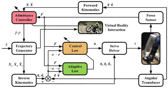
Figure 3.
Block diagram of AACVRI. k represents the serial number of control commands. , , and represent the desired position, velocity, and acceleration vectors in task space; , , and are desired position, velocity, and acceleration vectors in joint space; and represent the position and velocity joint errors. and are the acceleration and velocity of the model output.
3.1. Variable Admittance Controller
Admittance controllers utilize the mass-spring-damper model for describing the relationship between the end effector motion and the human-robot interaction force. Compared to impedance controllers whose input and output are reverse, admittance controllers are more suitable for human-robot force interaction. It is difficult to acquire the human position information as controller inputs for majority rehabilitation robots, and each joint of robots also needs an additional force sensor to achieve the force tracking in joint space.
A variable admittance controller is designed for human-robot reality interactions corresponding to virtual scenes. It processes the input of stiffness term to achieve varying stiffness along the trajectory. The relationship between the interaction force and the end effector motion is defined by the admittance law as follows:
where Md, Bd, and Kd are desired inertia, damping, and stiffness parameters. Fei represents the effective interaction force along the moving direction of trajectory (component force of interaction force, which is obtained by force sensor). X0 is the position vector of a set point in task space. If X0 is located on circle trajectory, the variation of stiffness term would be like a trigonometric function. p is the motion variable of admittance controller output. can be obtained by (5) directly, and is obtained by integrating .
Differing from other admittance controllers, this controller does not take the effector deviation as inputs of the model. However, this controller generates desired motions of the end effector and uses them for describing the mechanics property of a virtual bike pedal. In the effect of the designed stiffness term, a variable difficulty strength training depending on effector positions can be performed. It needs greater force to keep training movement in the zone which is far from the fixed point X0. The purpose of this design is to make users feel closer to bicycling during the training, and this design is also in accord with the movement characteristic of human lower limbs. The damping term can be regarded as resistance forces to the bicycle. The motion of LLR-II will be slowed by the effect of damping term if the interaction force is in a low level. Besides, Md, Bd, and Kd can also be changed by trigger feedbacks in order to respond to virtual events.
3.2. Adaptive Control
As mentioned above, the mechanical leg has a counterweight part for lightening load. The centroid position of the first link becomes a variable under the influence of the counterweight structure and the length adjustment function. Therefore, kinetic and potential energy terms in Lagrangian variation will change after the length adjustment. Although reference model parameters can be obtained, there are still deviations between the estimated and actual models. Adding the influence of interaction forces, common control strategies (e.g., proportional differential control) cannot perfectly adapt to such a variable parameter system. Hence, an adaptive control including interaction forces is developed to ensure the position accuracy. The control law was designed as follows:
where
, , and are estimated values with respect to the definition terms in (2). K and are time-invariant positive gain diagonal matrices. Equation (6) can be written as (8) by dynamics parameter linearization as follows:
where regressor Y is a function of , , and (the parameter linearization of , and ); is a joint variable function separated from . consists of the estimated value of the link length and the interaction force vector obtained from terminal force sensor; is the estimated value of the parameter vector.
Substituting (8) into the controlled object model (3), we obtain a closed-loop system which can be written as:
where and are parameter vectors which refer to true values in model built in (3). Thus, and represent parameter deviations between the estimated and actual models. To reduce these deviations, the time derivative of and are designed. Adaptive law is chosen as follows:
where learning steps and are constant symmetric positive definite matrices. and will update according to (10) in real time during the robot working, and they will gradually approach true values of those uncertain parameters from reference values which were set as initial values. Meanwhile, the system (9) is stable under control laws (8) and (10) as follows:
Let V: R → R be a continuously differentiable, positive definite, common Lyapunov function candidate shown as:
where and . The time derivative of (11) can be calculated as:
Substituting (9) into (12), we obtain
As mentioned, is a skew-symmetric matrix. Substituting adaptive law (10), (13) can be solved to yield
It is obvious that is positive definite and is semi-negative definite. Therefore, the closed-loop system is stable proven by Lyapunov stability theory. Furthermore, it can be found that is a non-increasing function, and the value of is maximum. It also means that , , and are bounded functions of time. Integrating the (14), we obtain
So and are square-integrable functions. As , , and are bounded, is bounded. In addition, observing the (9), can be considered bounded. When is bounded, is bounded. Hence, and are satisfied Barbalat Lemma; and when .
3.3. VR Training Environment
A virtual training environment with the forest bicycling competition theme is developed by Unity 3D to engage patients in strength training as shown in Figure 4 [50]. This approach changes the boring training experience of repeated cycling training, and it motivates users to fully train the lower limb strength.
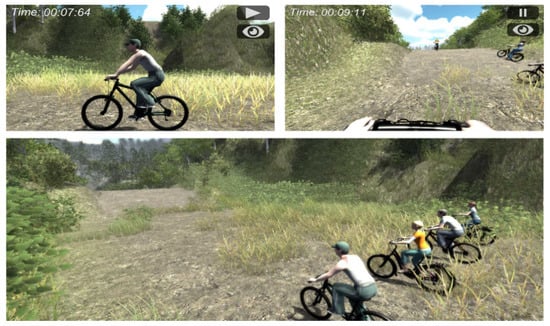
Figure 4.
Training screenshots from two perspectives (top left and top right) and the exhibition of the virtual scene (bottom). There are three NPC in competition (three from right). The top left corner of the screen displays the current training time, and two buttons in the top right corner are used for pausing training and switching perspective.
The track in the VR scene is about 800 m, including a 50 m uphill, a 50 m downhill, and a 70 m muddy road. The leg movement of the player character model will track the user’s actual training movement, and the moving speed of the bike model is related to the user’s leg movement. To further enhance users, there are three nonplayer characters (NPC) competing with users in this training. The virtual event feedbacks are generated by trigger functions when the player character enters into different road condition areas. The VR program will generate a local file, and the robot control system will call this local file in real time to update parameters of the admittance model according to its type. LLR-II will change admittance model parameters proportionally by a feedback coefficient to simulate the current road condition; coefficients are 1.0, 2.0, 0.75, and 1.5 in normal, uphill, downhill, and muddy conditions.
The training provides two perspectives for users, and users can also make a choice between the touch screen or the VR device in training based on their preferences. The training has four default levels of training difficulty, and doctors can select or adjust the difficulty level depending on the muscle strength of patients. Besides, the completed time in different difficulties can indirectly quantify or reflect the user’s current strength level.
4. Experiment
To evaluate the feasibility of RAAT and the controller performance, experiments were conducted on eight healthy subjects. Every subject confirmed the protocol of the experiment, and the research was carried out following the principles of the Declaration of Helsinki.
Experiments were conducted with LLR-II as shown in Figure 1. Each joint of LLR-II had mechanical, controller, and software limitations to prevent exceeding the user’s range of motion. Corresponding to the sitting and lying training modes, first (hip) joint rotation range also had two limitations in two training postures. Besides, the workspace of this robot was different in two training postures. Rated voltages of all electronic components in LLR-II were under 24 VDC. Two six-axis force sensors (Junde Technology A6D40) were used for measuring external forces. The data acquisition hardware (ART Technology PCI8622) measured sensor outputs at a sampling rate of 10 KHz. The upper computer ran development software (NI LabVIEW) to complete advanced computing. A physiological signal monitor device was used for recording variations of the user’s signs. It measured the heart and respiration rates using electrocardiogram electrode patches, and the body temperature was measured by an armpit temperature probe.
The subject was seated comfortably on the movable seat and then was transferred to the training position. After securing the user’s lower legs in orthotic boots, the assistant adjusted mechanical leg lengths to ensure the sagittal alignment of the user’s joints. The subject accepted passive cycling training in a relaxed state, and the average force array along the trajectory was recorded as the reference for active training. Several attempts were served as practice before the formal experiment to make subjects familiar with LLR-II. After subject’s heart rate returned to the baseline, the assistant helped the subject to wear physiological signal monitoring probes and then started the strength training.
5. Results
The results of experiments are shown in this section. Firstly, interaction force variability of the user under different virtual feedback are recorded; functions of the variable stiffness admittance controller and VR interaction mechanism are verified. Then, performances of adaptive controller and PD controller under this training method are compared. Finally, the feasibility of RAAT was verified by recording physiological signals of eight users during this training.
5.1. Variable Stiffness Admittance Controller and VR Feedbacks
Two mechanical legs of LLR-II remained in opposite positions during this training, and the motion state of LLR-II alternately depends on interaction forces from user’s left/right leg. That is to say, LLR-II is controlled by the leg in active zone (AZ), whereas the other is in the passive training state. Besides, there are two inertial motion zones where it was not easy to apply force on the end effector by lower limbs. The force variation of the right leg along the trajectory is shown in Figure 5, and it also depicts interaction forces in four event feedbacks.
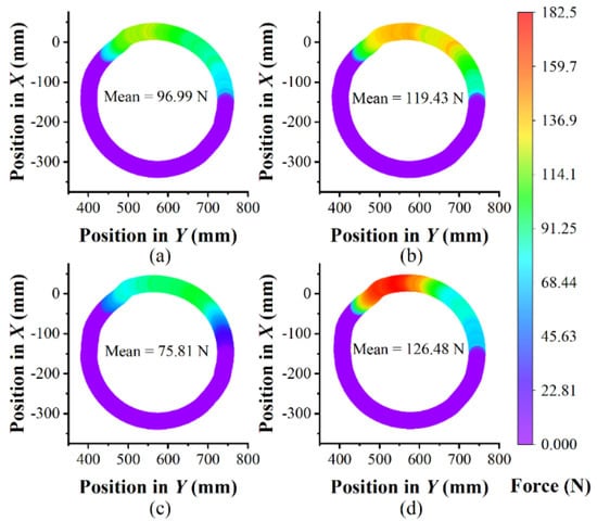
Figure 5.
Color mapped of effective interaction forces from user’s right leg in different event feedbacks along the trajectory: (a) general, (b) muddy, (c) downhill and (d) uphill. The start position is the leftmost point on the trajectory in Y axis direction, and the moving direction is clockwise during the training. Average force is just calculated from AZ (the zone except purple). The X and Y coordinates are same as Figure 2.
As expected from the design of this admittance controller, there is a difficult zone opposite to the point X0. Subjects need to push hard to keep the cycling speed, and force interactions will make subjects feel like riding a real bicycle when they press the pedal. Moreover, subjects adapted to the difficulty change caused by different event feedbacks and paid corresponding strength to complete the training. Subjects periodically pushed the end effector during the training, and they accepted alternating stimulations caused by the difficulty change.
5.2. Tracking Performance of Adaptive Controller
Figure 6 shows statistics of the effector position errors in 20 motion cycles. Actual effector positions are calculated from angular positions by forward kinematics, and angular positions of three joints are obtained by angular transducers. Results shown in Figure 6 are distances between the actual and desired positions in task space. From the histogram, it can be found that the proportion of errors between 3 mm and 4 mm are highest. In addition, position errors satisfy approximately normal distribution, and the 95% confidence interval was 5.638 ± 7.124 mm.
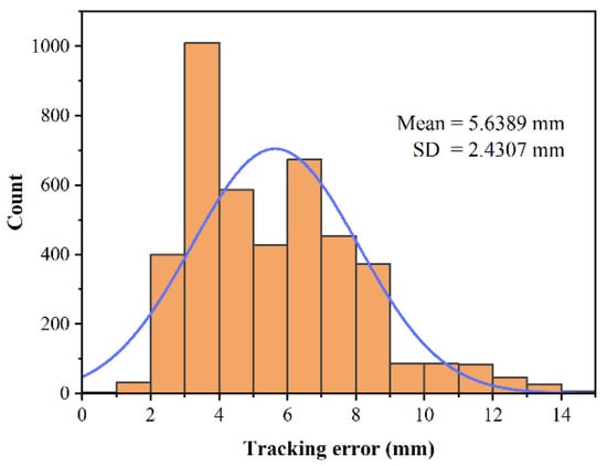
Figure 6.
Statistical results of end effector position errors.
Tracking performances of three joints are depicted in Figure 7. Average joint position curve is calculated from 20 motion cycles. The error curve is calculated depending on the comparison between the desired and average joint positions, and error bars are plotted based on standard deviations from 20 group data. Mean absolute errors of three joints are 0.399 deg, 0.464 deg, and 0.360 deg, respectively. The maximum errors of three joints are 1.108 deg, 1.004 deg, and 0.983 deg. It can be found that the third (ankle) joint shows better tracking performance than others. This might be the structure difference in drive trains; the component flexibility reduces the joint stiffness. Besides, errors around AZ are caused by interaction force disturbances. Since interaction forces are variable, standard deviations in AZ are also greater than other zones. These results can also be observed in Figure 5. In no interaction force area, the PID performance is similar to adaptive controller, but the adaptive controller has a better performance in interaction force affect areas (yellow area). The great majority of joint position errors were controlled under 1 deg, so the errors were in an allowable range. In summary, the tracking performance of this controller meets the requirement of the lower limb strength training.
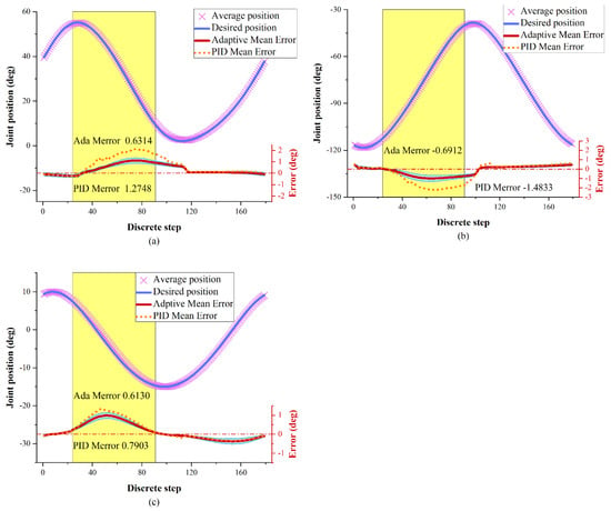
Figure 7.
Tracking performances of (a) joint q1, (b) joint q2 and (c) joint q3. The joints are affected by interaction forces around yellow areas (AZ). Average error (red line) and error bars (blue area) are plotted based on standard deviations from 20 group data.
5.3. Efficacy of RAAT
Physiological signals of a subject during the strength training were recorded as depicted in Figure 8. It shows that rates of heart and respiration increased significantly after the beginning of training, and the body temperature also increased slightly during the training. This indicates that subject’s metabolism and oxygen consumption had an increase during the strength training. In the uphill terrains, the interaction force of the subject increased significantly because the feedback change admittance parameters and improve training difficulty. Meanwhile, rates of heart and respiration are increased slightly. And then, the subject passed the difficult muddy area (slightly easy than uphill) after a short rest in downhill period, and the subject successfully reached the end. The user’s interaction and physiological signals decreased slightly in the downhill and then rebounded in the muddy road. The design of difficulty changes during the training gives users alternating stimulation and maintain users’ active state. From the record of interaction forces, it can be found that the subject was active and focused on whole training. The interaction force of this subject was up to 185.63 N, and mean value is 93 N during the training. Although the strength level of the subject had a downward trend in the latter half of the training, it was improved by VR feedback influence (including road condition changes, competitions, engagements, and other factors).
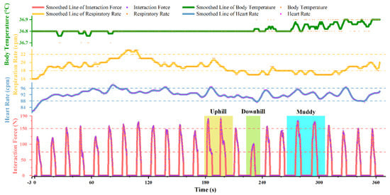
Figure 8.
Recorded variation of one subject’s physiological signals and interaction force during the strength training. The training started in the 0 s, and the physiological signals recorded before 0 s were resting values.
Recorded information of eight subjects participating in the strength training is listed in Table 1. The average heart rate and average respiratory rate of subjects in this training increased, on average, by 12.6% and 18.4%, respectively, compared with resting values. The peak body temperature was 0.125 °C higher than that in a resting state on average. These demonstrate that eight subjects kept a high active state in the training process, which proves the effectiveness and feasibility of this strength training under RAAT.

Table 1.
Record of eight subjects.
6. Discussion
This paper provides a new robot-assisted active training method for lower limb strength training. The experiment results suggest that: the variable admittance controller can enable the end effector to move as a virtual bike pedal whose mechanics property is designed; LLR-II can respond to different virtual events by changing admittance parameters; the adaptive controller can compensate deviations caused by dynamics parameter variations and human-robot interaction forces; RAAT can engage users to maintain active state in strength training.
This strength training is studied based on the combining of admittance control, adaptive control, and VR technology. In applications of VR technology to rehabilitation, there are more studies on upper limbs than lower limbs because it is easier to design virtual scenes for flexible upper limbs. The common method is creating task-specific training scenes by VR technology, and patients can improve their physical abilities by completing tasks [25,29]. The method shown in [30] is similar to our research, but it focuses more on the balance ability training. As mentioned earlier, the bicycle device is not friendly to patients in an early stage, whereas LLR-II can provide the same cycling training for patients with low muscle strength. Moreover, we paid more attention to motivating users in strength training by the scene and feedback designs, which is rare in related studies. In the field of admittance control, most studies utilize it as a buffer function to external forces [35,36,39,42]; robots will generate deviation motions from the desired trajectory in the direction of external forces. We made a meaningful attempt that designing the stiffness term of the admittance law to define mechanics property of the end effector, and the effector will move as a virtual pedal to cooperate virtual scenes. Additionally, parameters of the admittance controller are changed depending on feedbacks to perform VR interactions. In order to reduce the influence that interaction forces on joints, we used the principle of virtual work (also used in [36,37,41]) for calculating the joint compensation torque in (3). Specifically, we consider the link parameter deviation after length adjustment and the error of sensor acquisition force, so we added a regressor Z in the control input. For the modeling of LLR-II, this is a reasonable method for tracking accuracy.
Patients’ initiatives should be maximally inspired, which can lead to better rehabilitation progress. Therefore, our objective was providing an approach to improving independent training quality without additional intervening of medical staff. Although we created an exciting training atmosphere by Unity 3D, the main problem to be solved was how to control the robot to perform desired force interactions according to our expectations. At first, we used outputs of the admittance model for calculating the desired position by twice integrations [35,42], but the trajectory was not smooth. The main reason is that the greater force increases the moving distance of the end effector in every time step, which reduces the segmentation number of the desired trajectory. Besides, this method has a high requirement for the real-time sensor communication, so the tracking performance was inferior. Therefore, we separated the desired position from the velocity and acceleration, which can improve coverage degree of the desired trajectory and lighten the load of calculations.
However, there are still some errors around AZ under the control of the adaptive admittance controller, which might come from three sources: (1) the impact of interaction forces, (2) unconsidered mechanics factors and (3) the joint flexibility from timing belts. Under the RAAT, users will periodically and quickly apply force on LLR-II during the strength training. The end effector is obviously impacted around AZ by interaction forces, and interaction forces around AZ are varied rapidly and irregularly. The impact from interaction forces on joints cannot perfectly be compensated by the controller, so it leads to more errors around AZ. On the other hand, there might be some mechanics terms which are not considered in (3). Although the influence of these factors is smaller than considered factors, it could also cause tracking errors. At last, there are two long timing belts in drive trains of the first and second joints, which is also the main difference compared to the third joint in mechanical structure. The flexibility of timing belts might affect the performance of the adaptive controller, which is inferred from experimental results and needed further research.
Despite these tracking errors, we do believe that the strength training method under RAAT can be used in its current condition. The experimental results (Table 1) show that physiological signals of all subjects significantly increased during experiments. Average heart rate, average respiratory rate, and peak temperature were respectively increased by 12.6%, 18.4%, and 0.125 °C on average. These were due to an increase of the metabolism and oxygen consumption during the training. In addition, there was no significant decrease of interaction forces applied by subjects. The mean value of subjects’ interaction force during the training was 93 N, and maximum was up to 185 N. When subjects across different terrains during VR interactions, their interaction force will change alternately to stimulate their lower limb muscles. These all indicate that subjects were active and focused during the strength training. It can be said that RAAT is a feasible method for lower strength training.
7. Conclusions
This paper proposes an RAAT based on AACVRI for lower limb strength training. A designed virtual training environment is applied to motive users in cycling task-specific training. A variable admittance controller defines the mechanics property of the end effector. The VR human-robot interaction is performed by changing admittance parameters according to event feedbacks. The tracking accuracy is improved by an adaptive controller which compensates interaction forces and dynamics model deviations. RAAT is a feasible approach for lower strength training. In the whole process of this strength training, doctors only need to make some simple settings according to a patient’s state, and patients can independently complete high-quality strength training under RAAT.
Future works performed on adapting the impact of interaction forces and adding the consideration of other mechanics factors will further improve tracking performances. We will try to increase joint stiffness in mechanical structure or consider component flexibility in the control scheme. The immersion of the VR environment will be enhanced, and more virtual track scenes will be designed. Besides, clinical trials will be investigated to be clear about the specific effectiveness of this strength training.
Author Contributions
Conceptualization, H.W., J.N. and M.L.; methodology, Y.T. and X.W.; software, G.L.; prototype and experiment, M.L. and Y.T.; VR scene design, L.S.; writing—original draft preparation, M.L.; writing—review and editing, H.W. and J.N. All authors have read and agreed to the published version of the manuscript.
Funding
Please add: This work was funded by the National Key Research and Development Program of China (2019YFB1312500), the National Natural Science Foundation of China (U1913216) and the Science and Technology (S&T) Program of Hebei, China (19211820D, 20371801D).
Institutional Review Board Statement
The study was conducted according to the guidelines of the Declaration of Helsinki, and approved by Ethics Committee of China Rehabilitation Research Center (protocol code 2020-006-1; date of approval 25 February 2020).
Informed Consent Statement
Informed consent was obtained from all subjects involved in the study.
Conflicts of Interest
The authors declare no conflict of interest.
References
- Johnson, C.O.; Nguyen, M.; Roth, G.A.; Nichols, E.; Alam, T.; Abate, D.; Abd-Allah, F.; Abdelalim, A.; Abraha, H.N.; Abu-Rmeileh, N.M.E.; et al. Global, regional, and national burden of stroke, 1990–2016: A systematic analysis for the global burden of disease study 2016. Lancet Neurol. 2019, 18, 439–458. [Google Scholar] [CrossRef]
- Ochi, M.; Wada, F.; Saeki, S.; Hachisuka, K. Gait training in subacute non-ambulatory stroke patients using a full weight-bearing gait-assistance robot: A prospective, randomized, open, blinded-endpoint trial. J. Neurol. Sci. 2015, 353, 130–136. [Google Scholar] [CrossRef] [PubMed]
- Veerbeek, J.M.; van Wegen, E.; van Peppen, R.; van der Wees, P.J.; Hendriks, E.; Rietberg, M.; Kwakkel, G. What is the evidence for physical therapy poststroke? a systematic review and meta-analysis. PLoS ONE 2014, 9, e87987. [Google Scholar] [CrossRef]
- Hubbard, I.J.; Parsons, M.W.; Neilson, C.; Carey, L.M. Task-specific training: Evidence for and translation to clinical practice. Occup. Ther. Int. 2009, 16, 175–189. [Google Scholar] [CrossRef] [PubMed]
- Waddell, K.J.; Birkenmeier, R.L.; Moore, J.L.; Hornby, T.G.; Lang, C.E. Feasibility of high-repetition, task-specific training for individuals with upper-extremity paresis. Am. J. Occup. Ther. 2014, 68, 444–453. [Google Scholar] [CrossRef]
- Schaefer, S.Y.; Patterson, C.B.; Lang, C.E. Transfer of training between distinct motor tasks after stroke: Implications for task-specific approaches to upper-extremity neurorehabilitation. Neurorehabil. Neural Repair 2013, 27, 602–612. [Google Scholar] [CrossRef] [PubMed]
- Maciejasz, P.; Eschweiler, J.; Gerlach-Hahn, K.; Jansen-Troy, A.; Leonhardt, S. A survey on robotic devices for upper limb rehabilitation. J. Neuroeng. Rehabil. 2014, 11, 1–29. [Google Scholar] [CrossRef]
- Colombo, R.; Pisano, F.; Micera, S.; Mazzone, A.; Delconte, C.; Carrozza, M.C.; Dario, P.; Minuco, G. Robotic techniques for upper limb evaluation and rehabilitation of stroke patients. IEEE Trans. Neural Syst. Rehabil. Eng. 2005, 13, 311–324. [Google Scholar] [CrossRef] [PubMed]
- Mazzoleni, S.; Puzzolante, L.; Zollo, L.; Dario, P.; Posteraro, F. Mechanisms of motor recovery in chronic and subacute stroke patients following a robot-aided training. IEEE Trans. Haptics 2014, 7, 175–180. [Google Scholar] [CrossRef]
- Aprile, I.; Iacovelli, C.; Goffredo, M.; Cruciani, A.; Galli, M.; Simbolotti, C.; Pecchioli, C.; Padua, L.; Galafate, D.; Pournajaf, S.; et al. Efficacy of end-effector robot-assisted gait training in subacute stroke patients: Clinical and gait outcomes from a pilot bi-centre study. NeuroRehabilitation 2019, 45, 201–212. [Google Scholar] [CrossRef]
- Tole, G.; Raymond, M.J.; Williams, G.; Clark, R.A.; Holland, A.E. Strength training to improve walking after stroke: How physiotherapist, patient and workplace factors influence exercise prescription. Physiother. Theory Pract. 2020, 1–9. [Google Scholar] [CrossRef] [PubMed]
- Lexell, J.; Flansbjer, U.B. Muscle strength training, gait performance and physiotherapy after stroke. Minerva Med. 2008, 99, 353–368. [Google Scholar]
- Yi, Y.; Shim, J.S.; Oh, B.-M.; Seo, H.G. Grip strength on the unaffected side as an independent predictor of functional improvement after stroke. Am. J. Phys. Med. Rehabil. 2017, 96, 616–620. [Google Scholar] [CrossRef]
- Park, S.; Park, J.-Y. Grip strength in post-stroke hemiplegia. J. Phys. Ther. Sci. 2016, 28, 677–679. [Google Scholar] [CrossRef] [PubMed]
- Washabaugh, E.P.; Krishnan, C. A wearable resistive robot facilitates locomotor adaptations during gait. Restor. Neurol. Neurosci. 2018, 36, 215–223. [Google Scholar] [CrossRef]
- Ouellette, M.M.; LeBrasseur, N.K.; Bean, J.F.; Phillips, E.; Stein, J.; Frontera, W.R.; Fielding, R.A. High-intensity resistance training improves muscle strength, self-reported function, and disability in long-term stroke survivors. Stroke 2004, 35, 1404–1409. [Google Scholar] [CrossRef]
- Park, B.-S.; Kim, M.-Y.; Lee, L.-K.; Yang, S.-M.; Lee, W.-D.; Noh, J.-W.; Shin, Y.-S.; Kim, J.-H.; Lee, J.-U.; Kwak, T.-Y.; et al. The effects of a progressive resistance training program on walking ability in patients after stroke: A pilot study. J. Phys. Ther. Sci. 2015, 27, 2837–2840. [Google Scholar] [CrossRef] [PubMed][Green Version]
- Van Vulpen, L.F.; de Groot, S.; Rameckers, E.; Becher, J.G.; Dallmeijer, A.J. Improved walking capacity and muscle strength after functional power-training in young children with cerebral palsy. Neurorehabil. Neural Repair 2017, 31, 827–841. [Google Scholar] [CrossRef]
- Wu, M.; Landry, J.M.; Schmit, B.D.; Hornby, T.G.; Yen, S.-C. Robotic resistance treadmill training improves locomotor function in human spinal cord injury: A pilot study. Arch. Phys. Med. Rehabil. 2012, 93, 782–789. [Google Scholar] [CrossRef]
- Zhang, F.; Hou, Z.G.; Cheng, L.; Wang, W.Q.; Chen, Y.X.; Hu, J.; Peng, L.; Wang, H.B. iLeg—A lower limb rehabilitation robot: A proof of concept. IEEE Trans. Hum.-Mach. Syst. 2016, 46, 761–768. [Google Scholar] [CrossRef]
- Huang, Y.; Song, R.; Argha, A.; Savkin, A.V.; Celler, B.G.; Su, S.W. Continuous description of human 3D motion intent through switching mechanism. IEEE Trans. Neural Syst. Rehabil. Eng. 2020, 28, 277–286. [Google Scholar] [CrossRef] [PubMed]
- Li, M.; Liang, Z.; He, B.; Zhao, C.-G.; Yao, W.; Xu, G.; Xie, J.; Cui, L. Attention-controlled assistive wrist rehabilitation using a low-cost EEG sensor. IEEE Sens. J. 2019, 19, 6497–6507. [Google Scholar] [CrossRef]
- Rosado, W.M.A.; Ortega, A.B.; Valdes, L.G.V.; Ascencio, J.R.; Beltran, C.D.G. Active rehabilitation exercises with a parallel structure ankle rehabilitation prototype. IEEE Lat. Am. Trans. 2017, 15, 786–794. [Google Scholar] [CrossRef]
- Saposnik, G.; Levin, M.; Stroke Outcome Res Canada, S. Virtual reality in stroke rehabilitation a meta-analysis and implications for clinicians. Stroke 2011, 42, 1380–1386. [Google Scholar] [CrossRef] [PubMed]
- Bortone, I.; Leonardis, D.; Mastronicola, N.; Crecchi, A.; Bonfiglio, L.; Procopio, C.; Solazzi, M.; Frisoli, A. Wearable haptics and immersive virtual reality rehabilitation training in children with neuromotor impairments. IEEE Trans. Neural Syst. Rehabil. Eng. 2018, 26, 1469–1478. [Google Scholar] [CrossRef]
- Saposnik, G.; Teasell, R.; Mamdani, M.; Hall, J.; McIlroy, W.; Cheung, D.; Thorpe, K.E.; Cohen, L.G.; Bayley, M.; Stroke Outcome Res Canada, S. Effectiveness of virtual reality using Wii gaming technology in stroke rehabilitation a pilot randomized clinical trial and proof of principle. Stroke 2010, 41, 1477–1484. [Google Scholar] [CrossRef]
- Jack, D.; Boian, R.; Merians, A.S.; Tremaine, M.; Burdea, G.C.; Adamovich, S.V.; Recce, M.; Poizner, H. Virtual reality-enhanced stroke rehabilitation. IEEE Trans. Neural Syst. Rehabil. Eng. 2001, 9, 308–318. [Google Scholar] [CrossRef] [PubMed]
- Tao, G.; Garrett, B.; Taverner, T.; Cordingley, E.; Sun, C. Immersive virtual reality health games: A narrative review of game design. J. Neuroeng. Rehabil. 2021, 18, 1–21. [Google Scholar] [CrossRef]
- Caldas, O.I.; Aviles, O.F.; Rodriguez-Guerrero, C. Effects of presence and challenge variations on emotional engagement in immersive virtual environments. IEEE Trans. Neural Syst. Rehabil. Eng. 2020, 28, 1109–1116. [Google Scholar] [CrossRef]
- Song, C.G.; Kim, J.Y.; Kim, N.G. A new postural balance control system for rehabilitation training based on virtual cycling. IEEE Trans. Inf. Technol. Biomed. 2004, 8, 200–207. [Google Scholar] [CrossRef]
- Tatemoto, T.; Tanaka, S.; Maeda, K.; Tanabe, S.; Kondo, K.; Yamaguchi, T. Skillful cycling training induces cortical plasticity in the lower extremity motor cortex area in healthy persons. Front. Neurosci. 2019, 13, 927. [Google Scholar] [CrossRef]
- Evans, R.A.; Dolmage, T.E.; Mangovski-Alzamora, S.; Romano, J.; O’Brien, L.; Brooks, D.; Goldstein, R.S. One-legged cycle training for chronic obstructive pulmonary disease a pragmatic study of implementation to pulmonary rehabilitation. Ann. Am. Thoracic Soc. 2015, 12, 1490–1497. [Google Scholar] [CrossRef]
- Valent, L.; Dallmeijer, A.; Houdijk, H.; Slootman, H.J.; Janssen, T.W.; Van Der Woude, L.H.V. Effects of hand cycle training on wheelchair capacity during clinical rehabilitation in persons with a spinal cord injury. Disabil. Rehabil. 2010, 32, 2191–2200. [Google Scholar] [CrossRef]
- Bellman, M.J.; Downey, R.J.; Parikh, A.; Dixon, W.E. Automatic control of cycling induced by functional electrical stimulation with electric motor assistance. IEEE Trans. Autom. Sci. Eng. 2017, 14, 1225–1234. [Google Scholar] [CrossRef]
- Meuleman, J.; van Asseldonk, E.; van Oort, G.; Rietman, H.; van der Kooij, H. LOPES II-design and evaluation of an admittance controlled gait training robot with shadow-leg approach. IEEE Trans. Neural Syst. Rehabil. Eng. 2016, 24, 352–363. [Google Scholar] [CrossRef] [PubMed]
- Wu, Q.; Wang, X.; Chen, B.; Wu, H. Development of a minimal-intervention-based admittance control strategy for upper extremity rehabilitation exoskeleton. IEEE Trans. Syst. Man Cybern.-Syst. 2018, 48, 1005–1016. [Google Scholar] [CrossRef]
- Culmer, P.R.; Jackson, A.E.; Makower, S.; Richardson, R.; Cozens, J.A.; Levesley, M.C.; Bhakta, B.B. A control strategy for upper limb robotic rehabilitation with a dual robot system. IEEE-ASME Trans. Mechatron. 2010, 15, 575–585. [Google Scholar] [CrossRef]
- Cousin, C.A.; Rouse, C.A.; Duenas, V.H.; Dixon, W.E. Controlling the cadence and admittance of a functional electrical stimulation cycle. IEEE Trans. Neural Syst. Rehabil. Eng. 2019, 27, 1181–1192. [Google Scholar] [CrossRef] [PubMed]
- Yao, B.; Zhou, Z.; Wang, L.; Xu, W.; Liu, Q.; Liu, A. Sensorless and adaptive admittance control of industrial robot in physical human-robot interaction. Rob. Comput. Integr. Manuf. 2018, 51, 158–168. [Google Scholar] [CrossRef]
- Aguirre-Ollinger, G.; Colgate, J.E.; Peshkin, M.A.; Goswami, A. Design of an active one-degree-of-freedom lower-limb exoskeleton with inertia compensation. Int. J. Rob. Res. 2011, 30, 486–499. [Google Scholar] [CrossRef]
- Saglia, J.A.; Tsagarakis, N.G.; Dai, J.S.; Caldwell, D.G. Control strategies for patient-assisted training using the ankle rehabilitation robot (ARBOT). IEEE-ASME Trans. Mechatron. 2013, 18, 1799–1808. [Google Scholar] [CrossRef]
- Zhang, M.; Xie, S.Q.; Li, X.; Zhu, G.; Meng, W.; Huang, X.; Veale, A.J. Adaptive patient-cooperative control of a compliant ankle rehabilitation robot (CARR) with enhanced training safety. IEEE Trans. Ind. Electron. 2018, 65, 1398–1407. [Google Scholar] [CrossRef]
- Baek, J.; Cho, S.; Han, S. Practical time-delay control with adaptive gains for trajectory tracking of robot manipulators. IEEE Trans. Ind. Electron. 2018, 65, 5682–5692. [Google Scholar] [CrossRef]
- Ke, D.; Cong, S.; Kong, D.; Shen, H. Discrete-time direct model reference adaptive control application in a high-precision inertially stabilized platform. IEEE Trans. Ind. Electron. 2019, 66, 358–367. [Google Scholar]
- Lu, Y. Adaptive-fuzzy control compensation design for direct adaptive fuzzy control. IEEE Trans. Fuzzy Syst. 2018, 26, 3222–3231. [Google Scholar] [CrossRef]
- Abou Harfouch, Y.; Yuan, S.; Baldi, S. An adaptive switched control approach to heterogeneous platooning with intervehicle communication losses. IEEE Trans. Control Netw. Syst. 2018, 5, 1434–1444. [Google Scholar] [CrossRef]
- Zhang, Y.; Xu, Q. Adaptive sliding mode control with parameter estimation and kalman filter for precision motion control of a piezo-driven microgripper. IEEE Trans. Control Syst. Technol. 2017, 25, 728–735. [Google Scholar] [CrossRef]
- Deng, M.; Kawashima, T. Adaptive nonlinear sensorless control for an uncertain miniature pneumatic curling rubber actuator using passivity and robust right coprime factorization. IEEE Trans. Control Syst. Technol. 2016, 24, 318–324. [Google Scholar] [CrossRef]
- Yan, H.; Wang, H.; Vladareanu, L.; Lin, M.; Vladareanu, V.; Li, Y. Detection of participation and training task difficulty applied to the multi-sensor systems of rehabilitation robots. Sensors 2019, 19, 4681. [Google Scholar] [CrossRef]
- Wang, H.; Lin, M.; Lin, Z.; Wang, X.; Niu, J.; Yu, H.; Zhang, L.; Vladareanu, L. Virtual reality training system based on lower limb rehabilitation robot. J. Eng. Technol. 2018, 7, 119–122. [Google Scholar]
Publisher’s Note: MDPI stays neutral with regard to jurisdictional claims in published maps and institutional affiliations. |
© 2021 by the authors. Licensee MDPI, Basel, Switzerland. This article is an open access article distributed under the terms and conditions of the Creative Commons Attribution (CC BY) license (https://creativecommons.org/licenses/by/4.0/).