Article

The Research and Experiments on Contact Sealing Theory of the Underwater Clamp Connector

1
College of Mechanical and Electrical Engineering, Harbin Engineering University, Harbin 150001, China
2
Hangzhou Applied Acoustics Research Institute, Hangzhou 310012, China
*
Author to whom correspondence should be addressed.
Machines 2021, 9(11), 262; https://doi.org/10.3390/machines9110262
Submission received: 30 September 2021 / Revised: 23 October 2021 / Accepted: 27 October 2021 / Published: 30 October 2021
(This article belongs to the Section Machine Design and Theory)

Abstract

:
With regard to the sealing structure characteristics of the underwater clamp connector, based on the Hertz contact theory, this article studies the method of solving the extreme value of the radius of curvature on the two curved surfaces at the sealing contact point; first, the method of calculating the extreme value of the radius of curvature at any surface point of the rotary part is obtained, and then the equivalent radius of curvature is solved. Using finite element simulation to study the contact sealing characteristics without considering the edge thickness and width of the sealing gasket, it is verified that the Hertz contact theory is applicable to the metal contact theory of underwater clamp connectors. Then, the sealing simulation with the influence of the detailed dimensions of the sealing gasket is compared with the theoretical result of the direct application of the Hertz contact theory in the underwater clamp connector contact, and the theoretical correction coefficient of metal contact seal for underwater clamp connectors is introduced to solve the errors. The pressure sealing experiment is carried out on six-inch flange and metal sealing gasket, which proves that the coefficient can greatly enhance the theoretical calculation accuracy of the contact sealing of the underwater clamp connector.

1. Introduction

Deep-sea oil and gas exploration equipment is built onshore, installed independently on the seabed, and connected by underwater clamp connectors to form an integral subsea production system [1]. In practical work, the connector has to ensure the pipeline sealing under the burden of internal oil pressure changes and external disturbance impact [2]. Therefore, it is important to study the relation between the sealing and the force of the underwater clamp connector.
Reference [3] established the sealing theory of the clamp connector based on the Hertz contact theory, which mainly focuses on the contact angle and arc radius of the lens sealing, and verifies the relevant theories by finite element simulation and experiments. Reference [4] analyzed the mechanical state of the metal sealing under preload and operation, and summarized the design and theoretical calculation method of the metal sealing applicable to the high-pressure wellhead connector. Reference [5] showed the theoretical relationship between the contact stress of the metal sealing gasket and its structural parameters and working pressure based on the mechanical analysis method of the double-cone structure in a high pressure vessel. The equation of the unit sealing load of the metal sealing gasket under the condition of residual preload can be obtained from this relationship. This article also derived the change rules of contact stress and working pressure during the sealing process of the metal sealing gasket, and the structural parameters of the metal sealing gasket were the dominant factors influencing the rules. Reference [6] obtained the boundary condition of the connector sealing performance and the equation method of the contact pressure of the sealing surface based on the static metal sealing mechanism. A comparative experiment was also conducted to show that the connector optimized by this equation method has better sealing performance. Reference [7] attained the boundary condition of the underwater connector sealing and the equation of critical average contact pressure to ensure the connector sealing based on the principle of elastic superposition. Reference [8] obtained the relationship between the seal contact load and the locking force, and developed the contact model between the lenticular gasket ring and the flange based on the Hertz contact theory. In order to meet the requirements of connector sealing and strength, utilizing this model, the compression limit equation is further proposed. Reference [9] analyzed the leakage principle of the subsea connector and developed a new fractal porous media model. Besides, the permeability of the clamp connector can be worked out based on this media model and observation of the length-dependent mechanical model. Reference [10] attained the loading and unloading characteristics of the gaskets through experimentation, and these characteristics can be used to analyze the sealing performance of the bolt flange. By analyzing the sealing performance, it is proven that the distribution of contact stress has a greater impact on the sealing performance than the rotation limit of the flange allowed by ASME. Reference [11] put forward a sealing parameter and its critical value through the results of experiments and developed a new sealing standard. This standard can be used to compare and evaluate different types of metal-to-metal seals, especially in the petroleum industry. Reference [12] conducted a mechanical analysis of the pressure vessel’s closed system, and worked out some equations that can be used for design purposes. Stress concentration has also been studied numerically and analytically, and an approximate equation has been proposed to predict the contact area. Reference [13] showed a sealing structure based on static seal, and this structure can be used in the deep sea because of its better pressure sustainability. Finite element analysis was applied to the sealing structure for optimization and this analysis proved that the sealing structure could meet the demand. Reference [14] assumed a sealing structure for subsea pipeline maintenance and came up with an equation based on the principle of uniform contact pressure distribution and the thick-walled cylinder theory. Based on the analysis of finite element analysis results and theoretical calculation results, the acceptance criterion was developed. Reference [15] designed a sealing structure which can be used for the maintenance of underwater oil and gas pipelines. An equation that can be utilized to calculate the contact pressure was proposed based on the principle of mean pressure of the contact surface and the thick-walled cylinders theory. The finite element analysis was conducted and compared with the results of experiments, which proved the correctness of this equation. Reference [16] simplified the sealing structure and proposed a theoretical model related to the contact stress of the seal. The finite element method for analyzing the sealing structure was also conducted to verify the accuracy of the model. Reference [17] studied the connection mechanism of the spherical convex contact connector, and found that reducing the curvature radius of the end face of the spherical convex ring plays a good role in increasing the connection performance under low axial pressure.
Scholars at home and abroad have done a large amount of work on sealing contact characteristics; however, most of them directly apply the ready-made sealing theory without modifying it. Therefore, the experimental results and theoretical results generally have large errors, which need to be further studied. In this article, based on Hertz contact theory, the problem of addressing the seal of underwater clamp connectors is studied, the method for solving the extreme value of the radius of curvature of the contact point of the seal is analyzed, and the calculation method of the seal contact characteristic suitable for the underwater clamp connector is obtained. Finite element analysis was performed on the contact characteristics of the sealing structure and it was compared with theoretical analysis to solve the error correction coefficients under different working conditions. The core sealing structure of the underwater clamp connector was tested and studied to verify the applicability of the error correction coefficient.

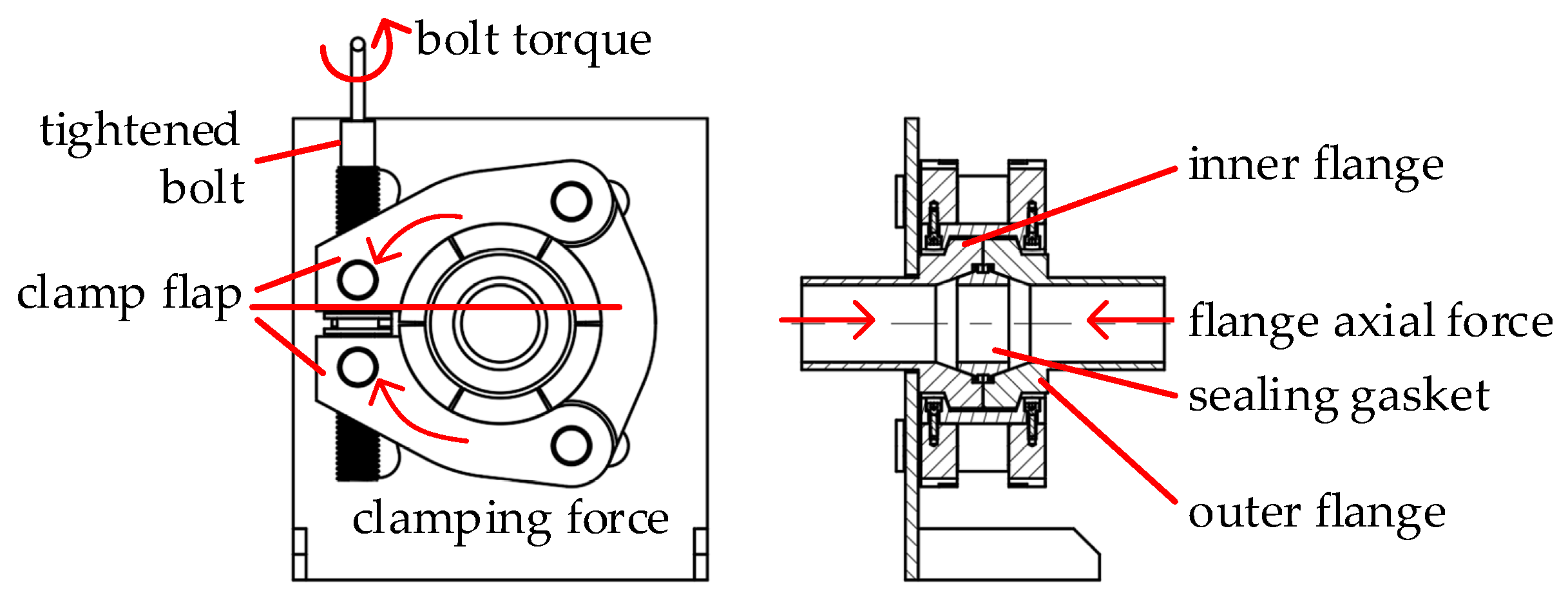
2. The Structure and Sealing Force of the Underwater Clamp Connector

The mechanical transmission of the underwater clamp connector is shown in Figure 1. The torque is transmitted to the clamping radial force of the clamp through the threaded connection of the tightened bolt, the clamp converts the radial force exerted by the clamp into the axial force of the flange by holding the flange tightly, and the two flanges clamp the sealing gasket to generate contact stress so as to achieve the final sealing requirement. In the underwater clamp connector, the metal sealing gasket and flange are directly used for sealing, as shown in Figure 2; the two flanges squeeze the metal sealing to form a sealing gasket; the axial force of the two flanges is the main factor in determining the sealing pressure; the thickness of the metal sealing edge, spherical radius, contact angle, and width are important dimensions related to sealing. Two non-coordinated solids initially come into contact at a point or line. Under a small load, they begin to deform at the point of contact, resulting in contact over a finite area, generating contact stress and strain; the sealing pressure can be obtained from the mean value of contact stress over the contact width, which can link the load pressure (in N) to the sealing pressure (in MPa) through contact theory and the sealing empirical equation.

3. Research on Contact Sealing Theory of Underwater Clamp Connector

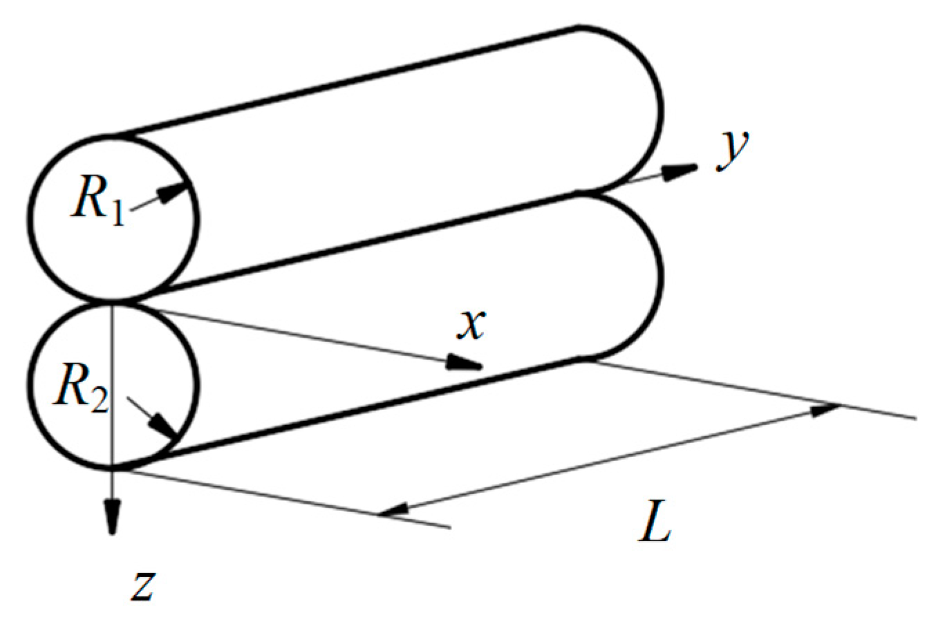
3.1. Comparison of Differences between Hertz Contact and Connector Contact Models

Hertz contact theory [18,19] provides an accurate solution for the approximate half-space contact problem, and analyzes in detail the contact problem between a rigid sphere and an elastic half-space which is a classical dharma contact. As shown in Figure 3, this problem is used as the basic model of the contact problem, which is used for analyzing more complex models.
As shown in Figure 4, the two elastic cylinders in the complex model extended by the Hertz contact model are in parallel contact. The normal pressure, F, and the indentation depth, d, are linearly proportional:
F = π 4 E * L d
where E* is the equivalent elastic modulus; L is the contact length of the cylinder in direction y;
The exact expression of the indentation depth and its relationship with the normal force F are related to the size and shape of the object. However, the correlation between the two is minimal.
The parallel contact between two elastic cylinders is the same as the contact between two elastic spheres. The contact half-width, a, is:
a R d
where R is the equivalent radius of curvature, which can be solved as follows:
1 R = 1 R 1 + 1 R 2
where R1 and R2 are the circle radius of the x-z sections of the two contacting cylinders.
In the x-z section, the contact stress function p(x) distributed along the x-axis in the z-axis direction is:
p ( x ) = p 0 1 ( x a ) 2
Among them, the maximum contact stress p0 (unit MPa) generated at the contact center at x = 0, z = 0 is:
p 0 = E * 2 d a = E * 2 ( d R ) 1 2 = ( E * F π L R ) 1 2
The actual contact model and cross-section between the flange of the underwater clamp connector and the metal sealing gasket are shown in Figure 5a,b. As shown in Figure 5c, the contact area rotation model (a) is expanded along the normal direction of the x-z plane. As shown in Figure 5d, when the metal sealing gasket and the flange contact half-width, a, are much smaller than the length of the arc segment of the metal sealing gasket, and the thickness of the edge of the metal sealing gasket is large enough, the force is equivalent to the contact of a cylinder with a radius equal to the radius of the sealing gasket arc and a cylinder with an infinite radius (Hertz contact model) after the tangential expansion of the revolving protrusion of the arc [20,21]. In Figure 5a, the hollow part of the sealing gasket axis will affect the calculation results of Hertz contact theory. As shown in Figure 5e, the metal sealing gasket is added to a solid model and the model in Figure 5e is used as an underwater clamp connection. According to the calculation model of Figure 5e, the calculation model of the contact problem of the connector is applied to the contact problem of the underwater clamp connector with reference to the Hertz contact theory.
Two elastic bodies of arbitrary shape with smooth surface and continuous second derivative are in contact, the two elastic bodies must have the maximum radius of curvature R 1 and R 1 and the minimum radius of curvature R 2 and R 2 at any section plane of each contact point, and each relative principal radius of curvature is, respectively, R and R [22]; the equivalent radius of curvature of the connector sealing contact point, R e , can be expressed as:
1 R e = 1 R 1 R = ( 1 R 1 + 1 R 2 ) ( 1 R 1 1 R 2 )
It can be inferred from Equation (6) that the equivalent radius of the contact point R e is related to the maximum and minimum radius of curvature of the two elastic contact surfaces at the contact point. In the next section, we will analyze the solution of the extreme curvature radius of the flange and the sealing gasket at the contact point.

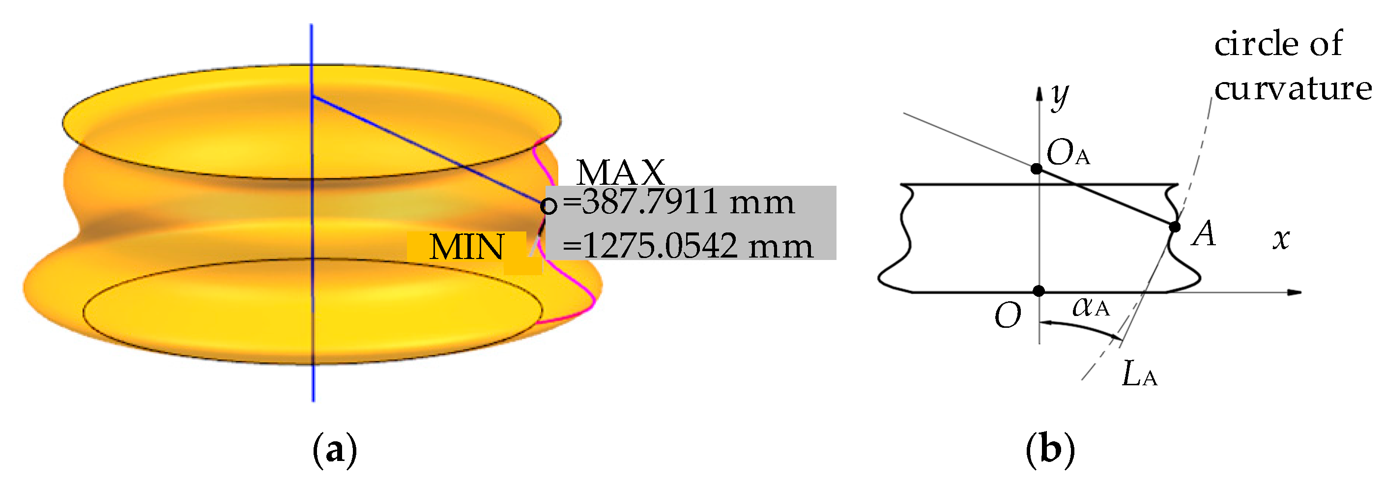
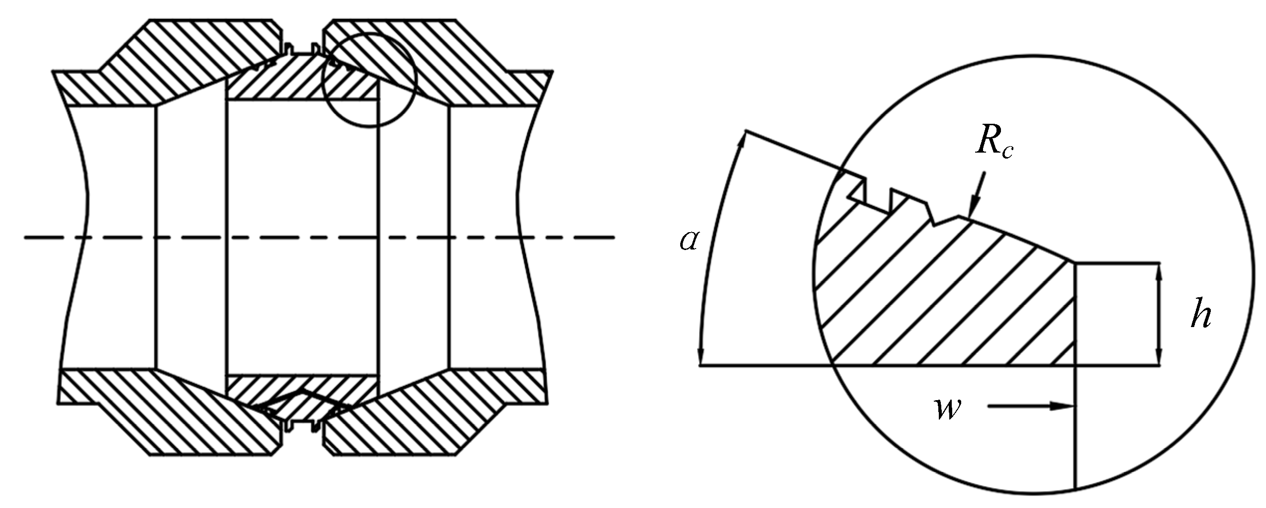
3.2. Research on the Radius of Curvature Extreme Value of the Sealing Contact Point of the Underwater Clamp Connector

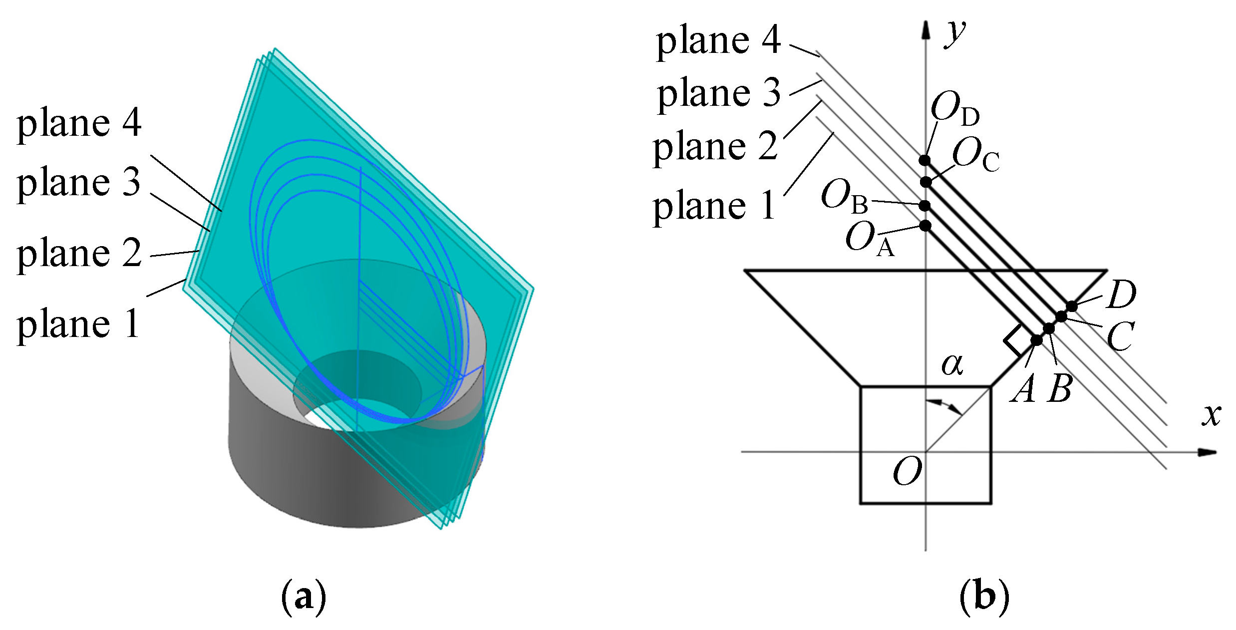
3.2.1. The Extreme Value of the Radius of Curvature at Any Point on the Flange Cone

As shown in Figure 6, the surface of the flange cone is a flared mouth formed by a revolving straight line; take a random point A on the flared mouth surface, and the radius of curvature on the plane OA-y on the straight line OA is ∞, which means the maximum radius of curvature at any point on the flared mouth formed by a revolving straight line is ∞, R 1 = ∞.
Draw the vertical plane 1 of the straight line OA through point A, and plane 1 intersects the axis of rotation y at OA and makes the curvature circle of point A on plane 1. After adjusting the angle α and the position of point A several times, it is found that the center of the vertical curvature circle of the straight line OA passing point A is entirely on the y-axis, and the curvature is the minimum curvature of any cross section passing point A.
According to the above conclusions, the minimum value of the radius of curvature of any point A, R 2 has been solved as follows:
R 2 = x A cos α
where xA is the coordinate of point A in the x-axis direction; α is the angle between AO and the y-axis.

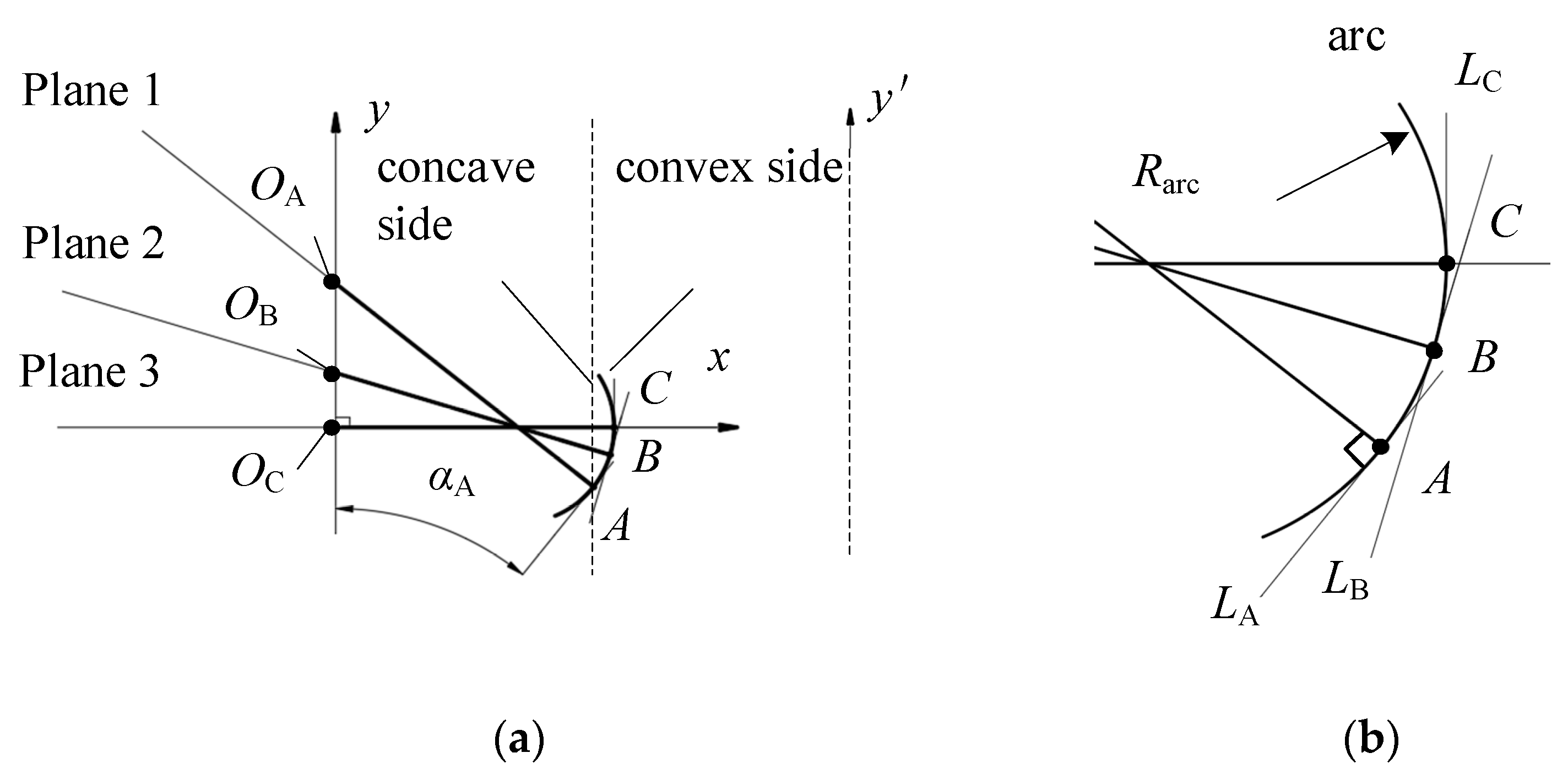
3.2.2. The Extreme Value of the Radius of Curvature at Any Point on the Contact Point of the Metal Sealing Gasket

As shown in Figure 7, the contact area of the metal sealing gasket is formed by circular arc rotation, which is the same as the research method of the flared mouth formed by a revolving straight line (after many measurements). It can be concluded that any circular arc revolves around any axis y to form a curved surface. The center of the circle of maximum or minimum curvature at any point A on the non-edge of the upper concave surface, OA, must be on the axis y or on the line of symmetry y with point A as the center axis; the line segment, AOA, corresponds to one of the extreme values, and another extreme value of the radius of curvature is the arc radius, Rarc.
According to the above conclusion (this conclusion only discusses the case where the concave surface faces the y-axis side, and the rest is the same), the extreme value of the radius of curvature (line segment AOA) of any point A has been solved and, the same as Equation (7), is as follows:
A O A = x A cos α A
where α A is the angle between the tangent of the arc at point A, LA, and the rotation axis, y. As the position of point A on the arc changes, the model formed by each tangent, LA, and the axis, y, can be regarded as a flared mouth model, which means that when the Rarc is infinite, the arc rotation model is equivalent to the flared mouth model. The extreme value of the radius of curvature of the metal sealing gasket contact point is judged as follows (see Appendix A for details):
{ R 1 = max { R arc , x A cos α A } R 2 = min { R arc , x A cos α A }

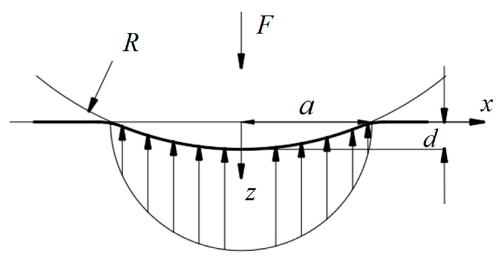
3.3. Application of Hertz Contact in Underwater Clamp Connector

To apply the Hertz contact theory to underwater clamp connectors, it is necessary to compare and analyze the differences between the two models to verify whether the Hertz contact theory is applicable to the contact seal of underwater clamp connectors, so as to obtain the connector contact theory calculation equation.
First, give the relationship between the axial force, Fa, exerted by the flange on the sealing gasket and the normal pressure of the metal sealing gasket (ignoring friction), F:
F = F a sin α
In the connector, the relationship between the normal pressure of the flange to the sealing gasket, F, and the pressing depth, d, is as follows:
F = π 2 4 E * d c d
where d c is the diameter of the circle of revolution at the contact center point in Figure 5b, mm; E * is the equivalent elastic modulus. Since the contact between the flange and the sealing gasket is in an elastic deformation state, E * can be solved by the following Equation [18]:
E * = 1 ν 1 2 E 1 + 1 ν 2 2 E 2
where ν 1 and ν 2 are Poisson’s ratio of flange and sealing gasket material; E 1 and E 2 are the elastic modulus of flange and sealing gasket material.
According to Equations (6), (7) and (9), the equivalent radius of curvature of the connector contact area, R e , is:
1 R e = ( 1 + 1 d c 2 cos α ) ( 1 R c 1 d c 2 cos α ) = 2 cos α d c 2 cos α R c d c
Then, the contact half-width, a, is:
a R e d
According to Equations (4) and (5), the relationship between the maximum contact stress pmax and the pressure at the contact center, F, can be obtained as:
p max = ( E * F π 2 d c R e ) 1 2
According to Equation (4), the average contact stress on the contact width 2 a , p ¯ , can be calculated:
p ¯ = p max 2 a a a 1 ( x a ) 2 d x = π p max 4
Equation (16) can be directly solved by the commonly used integral Equation (17).
a 2 x 2 d x = x 2 a 2 x 2 + a 2 2 arcsin x a + C

3.4. Derivation of Contact Sealing Theory of Underwater Clamp Connector

Under working conditions, the underwater clamp connector requires the flange to provide sufficient axial force to squeeze the metal sealing gasket, so that it can contact and seal against the thrust caused by the internal and external pressure difference, and the residual compression force is sufficient to ensure the sealing and avoid leakage. In engineering, the contact compaction effect and the sealing pressure are connected through an experiment. The experiment found that there is a linear relationship between the sealing pressure and the contact stress, and defines the ratio of the average contact stress applied to the unit effective area to the internal pressure, which is called the gasket coefficient, which is expressed by m. When the material of the metal sealing gasket is Incoloy 825, the gasket coefficient m = 6.5 [23], namely:
p ¯ = m p in
In Figure 5e, the theoretical calculation equation of contact sealing of the ideal calculation model of underwater clamp connector is obtained by combining Equations (10), (15), (16) and (18):
p in = 1 4 m E * F a d c R e sin α
The above equation shows that the sealing pressure p in is related to material parameters m and E * , structural parameters d c , R e , and α, and the external load parameter Fa.
The ideal calculation model (Figure 5e) considers the inner diameter of the metal sealing gasket to be 0. In the actual situation (Figure 5a), there is a large oil cavity inside the flange sealing gasket. The diameter of the oil cavity is related to the thickness of the sealing gasket edge, h (Figure 2). The following part will use finite element simulation to verify the ideal calculation model (Figure 5e), the contact theory calculation equation, research on the influence of the intervention of parameters, h and w, on the contact sealing theoretical calculation, and, finally, revise the contact sealing calculation equation.

4. Simulation Research on Metal Contact Sealing Theory of Underwater Clamp Connector

From the perspective of finite element simulation, specific data on the maximum contact stress, pmax, and the flange axial force, Fa, can be given. Combining Equations (10) and (15), one can obtain the theoretical calculation relationship between the two, corresponding to the ideal calculation model (Figure 5e):
p max = ( E * F a π 2 d c R e sin α ) 1 2
When the material and size of the connector is certain, except for the pmax and Fa, the other parameters are all constants. The theoretical calculation equation for pmax and Fa and multiple sets of simulation data can be mutually verified. Take, for example, the set of material and size parameters as shown in Table 1.

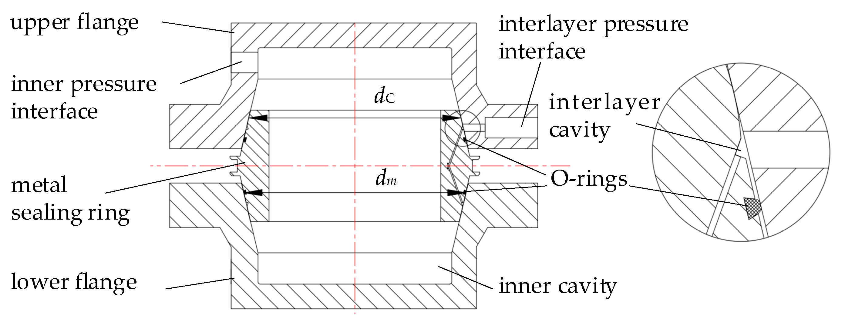
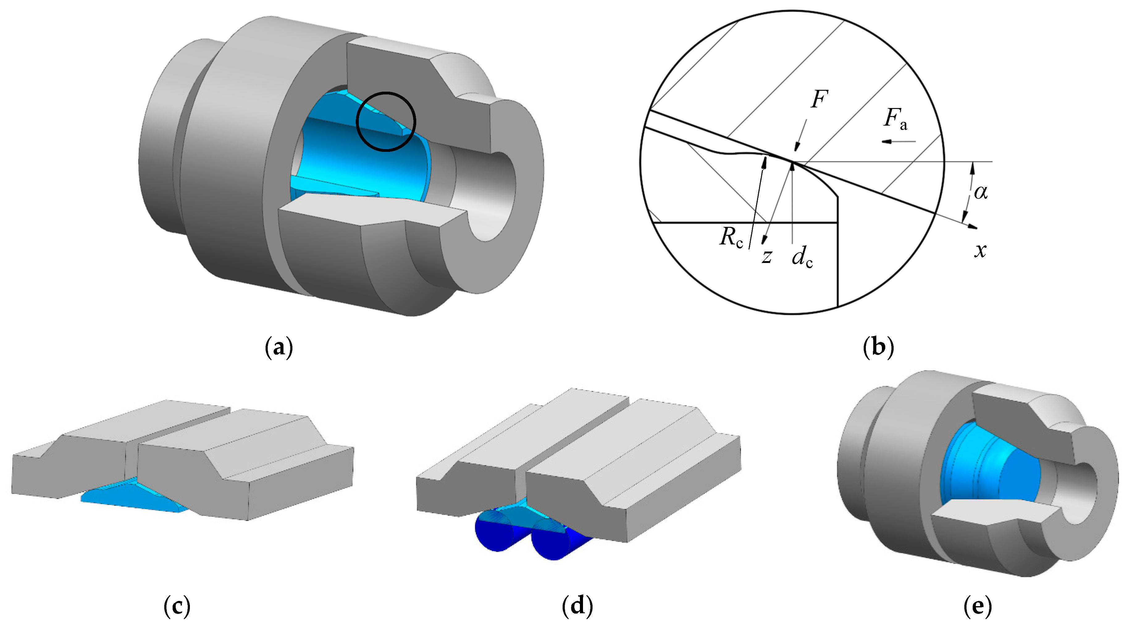
4.1. Establishment of Contact Model between Flange and Metal Sealing Gasket

The sealing structure of the underwater clamp connector is mainly a rotatory axisymmetric structure with the inner flange and the outer flange extruding from the metal sealing gasket. When subjected to the axial external force, the overall structure receives uniform force, and the fixed constraint and load are also symmetrical along the central axis, and therefore it can be solved by the sheet symmetry model, thereby decreasing the number of meshes and reducing the calculation time. Using the three-dimensional modeling software UG, one can perform parametric modeling of flanges and metal sealing gaskets. The parameterized dimensions include h, w, R c , and α . The sheet body model is given according to the dimensions in Table 1, and then imported into Ansys Workbench for static contact analysis.

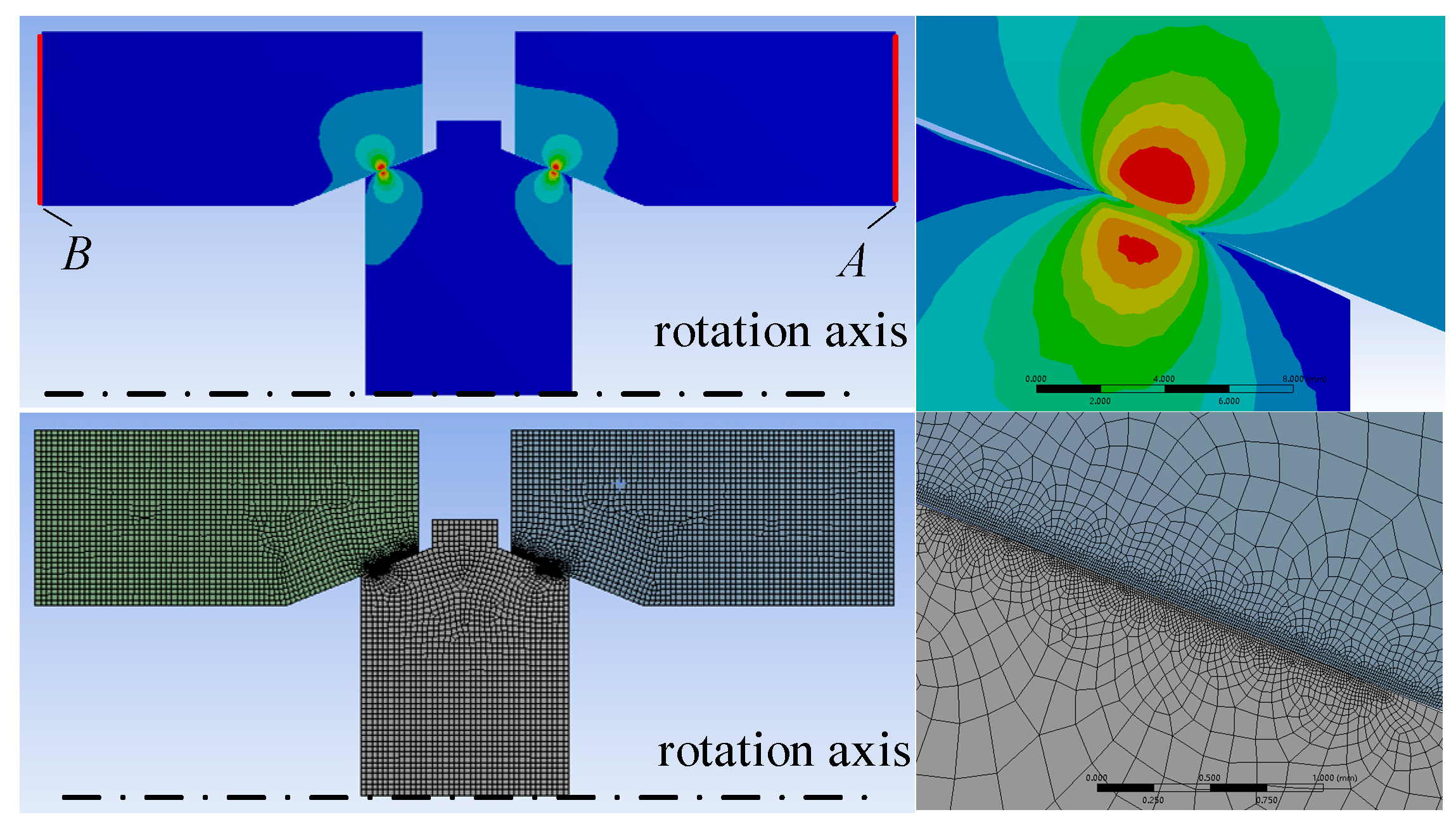
4.2. Establishment of Finite Element Model of Sealing Structure

As shown in Figure 8, the finite element simulation model of the clamp connector flange and the metal sealing gasket contact (same as Figure 5e), the material property settings are the same as those in Table 1.
The overall mesh is divided into 1 mm spaces, and the contact surface mesh is refined to 0.01 mm. The displacement load is applied at the right edge of the right flange along A, and the left flange is applied along the left edge B fixed constrained load. Set the solving results, include the maximum stress of the sealing gasket, the maximum stress of the flange, the maximum contact stress, pmax, and the axial force of the flange, Fa.

4.3. Solution and Errors of Data Analysis

By using the finite element solution, the displacement load ranges from 0.001 mm to 0.5 mm, the flange axial force, Fa, ranges from 659 N to 498890 N, and the maximum contact stress, pmax, ranges from 33.9 MPa to 958 MPa. The theoretical calculation of pmax has an error range from 3% to 6% compared to the simulation result in this range. As shown in Table 2, due to the large amount of data, only 11 key sets of data are selected for detailed analysis.
The data selection is based on the following: in the preloaded state, it should be ensured that the circular arc surface of the metal sealing gasket has a sufficient compression ratio pressure per unit effective area. The minimum value of the compression ratio pressure is called the minimum preload ratio pressure, y. For different materials, the minimum preload ratio pressure y is also different. The minimum preload ratio pressure of material Incoloy 825 is y = 179.3 MPa, that is, the maximum contact stress should exceed the minimum preload ratio pressure before the gasket coefficient in Section 3.4 can be applied; therefore, most pmax in the simulation data lower than the minimum preload ratio pressure y are abandoned. Considering the minimum preload ratio pressure, when the displacement load boundary is 0.0235 mm, the pmax is 180 MPa and the Fa is 18,640 N. In addition, the before-mentioned theoretical calculations and simulations are based on the elastic deformation of the material, therefore most of the data where the maximum stress of the metal sealing gasket and flange exceeds the yield strength of the material are not selected as the analysis data. Considering the yield strength of the material, when the displacement load boundary is 0.093 mm, the maximum stress of the metal sealing gasket and flange are 220.12 MPa and 226.74 MPa, and the Fa is 81,280 N. It can be seen from the above analysis that the data on the displacement load from 0.3 mm to 0.9 mm in Table 2 are completely valid data, which serve as the main analysis data, and the remaining data have relatively large errors, which are used as secondary analysis data.
The following conclusions can be drawn from the displacement load from 0.03 mm to 0.09 mm:
  • When the axial force is used as the known maximum contact stress, the deviation in the simulation value is 3.86% to 4.63% lower than the theoretical value;
  • The error decreases with the axial force showing a decreasing trend;
  • The maximum contact stress is the power function of the axial force. The data near the edge below the minimum preload pressure and above the yield strength basically meet the above conclusions.
The reason why the above simulation value is lower than the theoretical value is as follows:
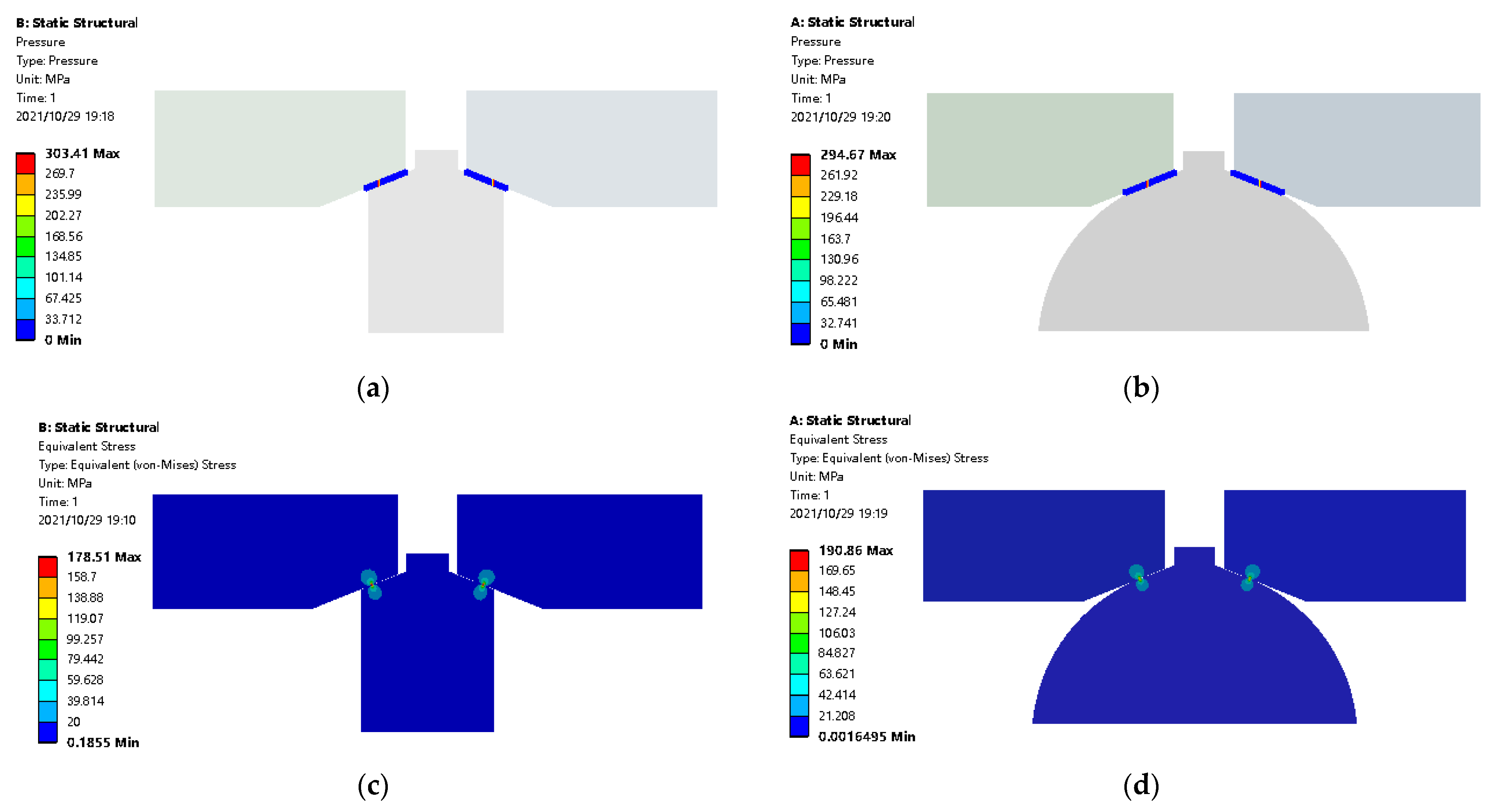
  • The theoretical calculation is more in line with the model in which the sealing gasket is a full circle which rotated into an approximate sphere (the arc center is a sphere on the axis of rotation). The metal sealing gasket axis in the simulation model cuts off two parts at both ends, which is closer to the actual situation. As shown in Figure 9, when the other errors have the same influence, when Fa = 51,990 N, the ends cut off model is about 12% lower than the full circle rotation model. The maximum contact stress is about 6.5% lower. The maximum contact stress is lower than the overall maximum stress, which is more beneficial for sealing higher pressure before the material yields;
  • The theoretical calculation model is more in line with the infinite radius of curvature of the contact point. The smaller the radius of curvature, the greater the errors;
  • There is an error in the method of solving the equivalent radius of curvature used for theoretical calculation.

5. Revision and Experimental Research on Contact Sealing Theory of Underwater Clamp Connector

5.1. Correction Coefficient of Contact Sealing Theory of Underwater Clamp Connector

In Section 3.1, the theoretical calculation corresponds to the calculation model in Figure 5e, and the actual model in Figure 5a needs to increase the influence of h, w, pin, pout (water depth pressure), and other factors. There are large errors in the calculation results of Equations (19) and (20). It is difficult to derive the role of h and w in the calculation of the contact seal from the theoretical equation. We can see from Table 2 that the biggest difference between the first error to the last one is merely 2.14%. Then, we can make an assumption that the deviation between theoretical and experimental contact stress is a linear relationship. Now, we use a correction coefficient khw of the actual model of the connector to calculate the contact sealing, and to modify the Equation (21) as follows:
p max = k hw ( E * F a π 2 d c R e sin α ) 1 2
Each set of specific materials, size parameters, and internal pressure corresponds to a specific correction coefficient khw. A series of khw values can be obtained through the combination of simulation and Equation (20), and the correction coefficient khw obtained is used to modify the Equation (19):
p in = k hw 4 m ( E * F a d c R e sin α ) 1 2
The following takes the specific size as an example to calculate the corresponding khw value. The size data of the metal sealing gasket are shown in Table 3, and the other material parameters are checked according to Table 1.

5.2. Correction Coefficient under Different Oil Pressure and Water Depth

In the internal pressure range of 20.7 MPa to 41.4 MPa, seven groups of pressure effects are divided, and the maximum contact stress of the sealing extreme under each pressure is obtained through simulation. The flange axial force is brought into the Equation (20) to obtain the maximum contact stress without the influence of half width, thickness, and internal pressure, and to compare the simulation value with the calculated value to obtain the correction coefficient khw under the current size and pressure, as shown in Table 4. The table contains the simulated pmax value which was affected by the internal influence of h, w, and pin, while the calculation of pmax in Equation (20) was not affected by the influence of h, w, and pin. From the correction coefficients under various pressures, it can be seen that pressure changes have little effect on the value of the correction coefficient. Since the minimum preload pressure of Incoloy 825 is y = 179.3 MPa, Equation (20) is only applicable when pmaxy, and large errors will occur if the range is exceeded. Therefore, the correction coefficients in Table 5 are applicable to pressures of 24.1 MPa and above.
Due to the fact that pressure change in the pipeline has little effect on the correction coefficient, in order to facilitate the study, the influence of the variable of the pipeline pressure is ignored below, and then the influence of the water depth pressure on the correction coefficient is studied. In the simulation model, seawater pressure is applied to the part of the metal sealing gasket in contact with the seawater. The measured simulation data are shown in Table 5, and the khw value in the table shows that the water depth has a small effect on the correction coefficient.
In summary, the correction coefficient khw can be obtained through theoretical calculation Equation (20) and simulation. The influence of water depth and internal pressure can be ignored during simulation, and only parameters such as materials and dimensions are considered to simplify the simulation process. The six-inch underwater clamp connector is based on the materials in Table 1 and the dimensions in Table 3, and the correction factor khw is about 0.78. The revised sealing pressure and axial force of the underwater clamp connector are obtained according to Equation (22). By analogy, the above-mentioned metal contact sealing theory of underwater clamp connectors is suitable for the sealing problems of oil pipeline connectors of commonly used sizes (6 to 36 inches) on the seabed, and has a wide range of applications.

5.3. Verification Test of Contact Sealing Theory of Underwater Clamp Connector

The contact sealing test is mainly to verify the metal contact sealing theory of the connector in Equation (22) of Section 3.1, which is derived based on the Hertz contact theory and corrected by simulation. This theory only involves two flanges and one sealing gasket (including one metal sealing gasket and two nitrile rubber O-rings); the contact surface is only between the metal sealing gasket and the flange, the inner flange and the outer flange has no contact. The principal diagram of the test is shown in Figure 10. The test is divided into two parts: the inner cavity pressure sealing test and the Interlayer cavity pressure sealing test. The inner cavity pressure seal test is to verify whether the metal sealing can achieve the prevention of the oil leakage in actual work; the interlayer pressure seal test mainly verifies whether the metal contact sealing surface is formed under a certain water depth. When the interlayer pressure interface is equipped with a shut-off valve, it can isolate sea water.

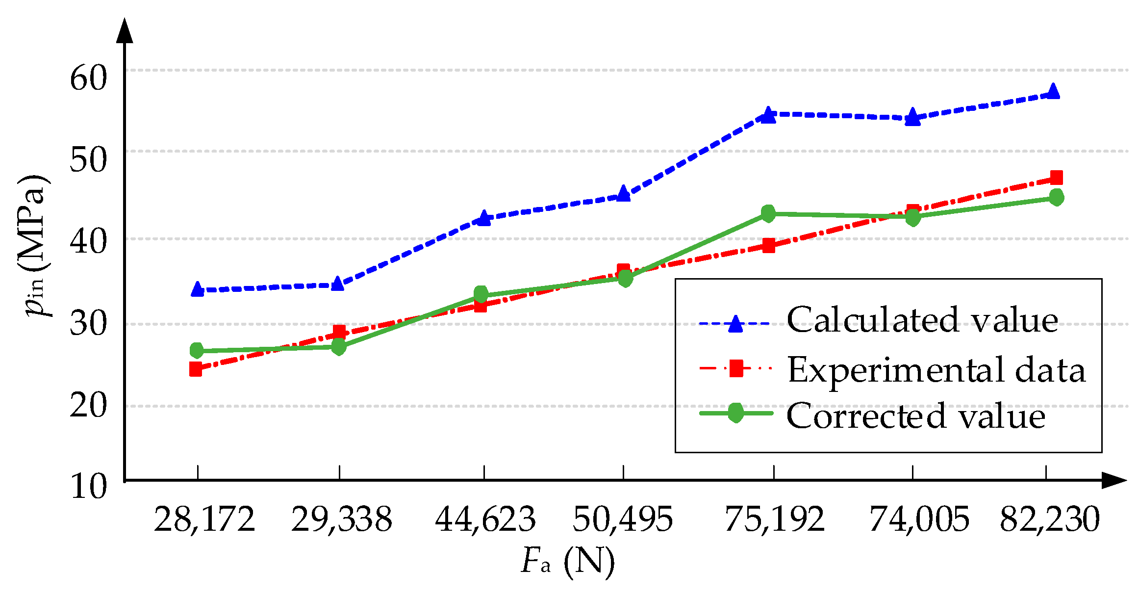
5.3.1. Inner Cavity Pressure Sealing Test

In the inner cavity pressure sealing test, the inner and outer flanges are squeezed by a press machine with a constant force, Fpress, and the inner cavity is pressurized by a pressure pump. The liquid pressure on the flange generates an axial force, Fa-liq, summed the metal sealing gasket receives an axial force, Fa, is equal to the constant force provided by the press. The Fa is obtained indirectly in Equation (23):
F a = F press F a liq = F press π d C 2 4 p in
The input of the inner cavity pressure sealing test is the constant force of the press, Fpress, and the output is the maximum value of the sealing liquid pressure under this force. The specific experimental steps are as follows:
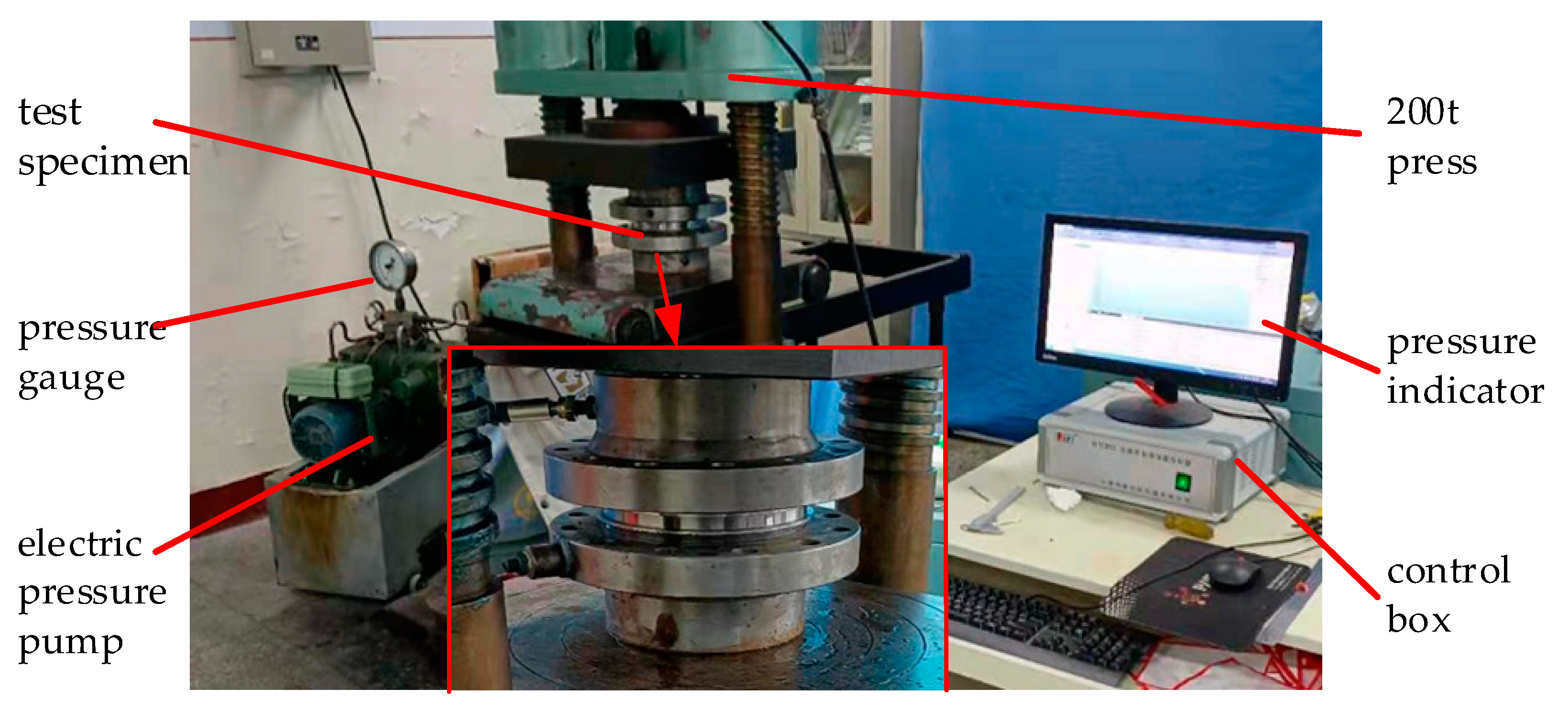
  • Preparation of test equipment: metal sealing gasket, inner flange, outer flange, O-rings, 200 t press (including control box and pressure indicator), electric pressure pump (including valve, pressure gauge, water tank), oil pipes, and joints;
  • According to the schematic diagram of the inner cavity pressure shown in Figure 11, build a test bench, check the oil circuit interface connection, check the sealing gasket, clean the sealing surface, and test pressure and the oil circuit tightness;
  • The initial pressure of the press is 60 t;
  • Turn on the electric pump and observe the leakage between the two flanges and the pressure indicator. When the pressure indicator does not rise significantly or there is visible leakage, stop the pressure and observe the rate of decrease in the pressure indicator. When it is less than 5% per hour and less than 3.45 MPa per hour, hold for 15 min, and record the pressure. According to API Spec 6A [24], the acceptable pressure drop in the test is the same as the rate of decrease;
  • Increase the pressure of the press by 10 t;
  • Repeat step 4 and step 5, the test does not end until the holding pressure exceeds 41.4 MPa after timing.
The experimental data are shown in Table 6. The pressure range of the press is from 60 t to 120 t, the sealing pressure is from 24.3 MPa to 47.5 MPa, and the pressure drop meets the standard requirements. Through Equation (23), the flange axial force required by the corresponding sealing holding pressure under the load of each press can be obtained. As shown in Table 7 and Figure 12, the theoretical pressure values before and after the correction are obtained by Equations (19) and (22), and the data comparison shows:
  • The sealing pressure error before correction is between −17.6% and −28.8%, and it is between −9.24% and 5.56% after correction. Therefore, the error after correction is significantly reduced;
  • The error before and after correction fluctuates greatly.
The reasons for the errors are:
  • The error between the pressure indication of the press and the actual provided pressure;
  • The error between the indicator in hydraulic gauge of the pressure pump and the actual liquid pressure;
  • The pressure drop of the hydraulic oil circuit;
  • The experimental error fluctuates greatly. The main reason is that the liquid pressure shares most of the press pressure when the inner cavity is pressed. The axial force acting on the sealing gasket only accounts for 4% to 8% of the axial force provided by the press. The error fluctuation of the test measurement data will amplify the Fa error fluctuation obtained by Equation (23).

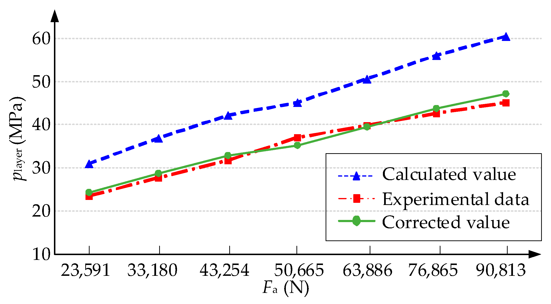
5.3.2. Interlayer Cavity Pressure Sealing Test

The principle and steps of the Interlayer cavity pressure sealing test and the inner cavity pressure sealing test are basically similar, and the differences are explained in detail below, refer to Equation (23). The Fa is indirectly obtained as:
F a = F press F a layer = F press π ( d m 2 d C 2 ) 4 p layer
where Fa-layer is the axial force of the interlayer liquid pressure on the flange; d m is the diameter of the dovetail groove installed on the O-ring; player is the interlayer liquid pressure.
The steps of the interlayer cavity pressure sealing test are the same as those in Section 3.2, however, the specific applied pressure values are different. Among them, the initial pressure of the press given in step 3 is 8 t; step 5 increases the pressure of the press by 2 t each time. The experimental data are shown in Table 8. The pressure range of the press is from 8 t to 20 t, the sealing pressure is from 23.3 MPa to 45.1 MPa, and the pressure drop meets the standard requirements. The flange axial force required by the corresponding seal holding pressure under the load of each press can be obtained by Equation (24), and the value is 181.8 mm. As shown in Table 9 and Figure 13, the theoretical pressure values before and after the correction are obtained by Equations (19) and (22). The comparison of data shows that:
  • The sealing pressure error before correction is between −18.2% and −25.3%, and the sealing pressure error after correction is between −4.55% and 4.83%. Therefore, the error after correction is significantly reduced;
  • Compared to before and after correction in Section 4.3, the error fluctuation is reduced.
The reason for the error is basically the same as that in Section 5.3.1. The reason for the reduction in error fluctuation is that, during the Interlayer cavity pressure sealing test, the axial force acting on the sealing gasket accounts for 29.5% to 45.4% of the axial force provided by the press, and the proportion is significantly increased. The influence of error amplification caused by Equation (24) is reduced.
The error of the comprehensive internal cavity and Interlayer cavity pressure sealing test results shows that: after the correction of the metal sealing theory of the clamp connector, and after considering the influence factors such as the width of the sealing gasket and the edge thickness, the original error is reduced from −17% to −30% to −6% to 10%, and the error accuracy is significantly improved.

6. Conclusions

In this article, the method for solving the extreme value of the radius of curvature of the contact point of the seal is analyzed, and a calculation method for the seal contact characteristics of the underwater clamp connector based on the Hertz contact is obtained. The simulation and theoretical results of the contact characteristics of the sealing structure were compared, the error correction coefficients under different working conditions were solved, and the applicability of these coefficients was verified through experiments. The sealing theoretical model established in this article is suitable for full-size underwater clamp-type connectors using lenticular sealing gasket, and the error correction coefficient is mainly suitable for six-inch connectors. The research in this article provides some positive guidance to the design and research of the sealing structure of underwater connectors. The main conclusions are as follows:
  • A method for solving the radius of curvature of rotating parts such as metal sealing gaskets and flanges is proposed. This method is extended to solve the problem of the extreme value of the radius of curvature at any point on the arbitrary curved surface;
  • It is verified that the Hertz contact theory is applicable to the contact calculation model of the clamp connector, and the error is within 6%. Analytical equations obtained in this article can be used in future engineering design and the simulation, and tests are not needed anymore;
  • It can be seen that the theory, simulation, and experiment are highly consistent, which proves that the error correction coefficient, khw (in this article is 0.78), of the six-inch connector can greatly improve the accuracy of theoretical calculation in practical application, which is a great innovation and breakthrough. The accuracy of the analytical results is good enough to be used in the engineering application.

Author Contributions

Conceptualization, F.Y., H.S. and W.W.; methodology, F.Y. and G.W.; validation, H.S., W.W. and F.Y.; formal analysis, F.Y. and H.S.; investigation, X.H., W.W. and Z.Y.; resources, Z.Y., H.G. and L.W.; data curation, K.J. and D.L.; writing—original draft preparation, F.Y. and H.S.; writing—review and editing, F.Y. and K.J.; funding acquisition, L.W., H.G. and F.Y. All authors have read and agreed to the published version of the manuscript.

Funding

This research was funded by the National Natural Science Foundation of China, grant number 52001089; China Postdoctoral Science Foundation, grant number 2020M670889; Heilongjiang Provincial Natural Science Foundation of China, grant number LH2021E046 and E2018021; Fundamental Research Funds for the Central Universities, grant number 3072021CFT0701 and 3072020CFT0704; The School Land Integration Development Project of Yantai (development and test platform of subsea production system), grant number 2019XDRHXMPT29.

Institutional Review Board Statement

Not applicable.

Informed Consent Statement

Not applicable.

Data Availability Statement

Not applicable.

Conflicts of Interest

The authors declare no conflict of interest.

Appendix A

The extreme value of the radius of curvature at any point on the revolving surface of any curve is shown in Figure A1, according to the research content of the extreme value of the radius of curvature of the flared mouth and the circular arc surface, the rotation problem can be extended to any derivative continuous curve rotation. The same as the previous method, the following conclusion can be obtained: the arbitrary derivative continuous curve revolves around the axis y. Curved surface, the center of the circle of maximum or minimum curvature at any point A on the non-edge of the concave side of the surface, OA, must be on the axis, y, or the symmetry line y’ with point A as the center axis y; the line segment, AOA, corresponds to one of the poles. The other extreme value of the radius of curvature is the radius of curvature of point A in the plane x-y, RAx-y.
Figure A1. The extreme value of the radius of curvature at any point on arbitrary curve rotation surface. (a) Three-dimensional model of arbitrary curve rotation; (b) Cross-sectional view of arbitrary curve rotation.
Machines 09 00262 g0a1
According to the above conclusion (this conclusion only discusses the case where the concave surface faces the y-axis side, and the rest is the same), the extreme value of the radius of curvature (line segment AOA) that has been solved for any point A is the same as Equation (8).
Suppose the function of any derivative continuous curve in the plane x-y is: x = f (y), then the radius of curvature of any point on the curve [25], RAx-y, is:
R A x - y = ( 1 + f ( y A ) 2 ) 3 / 2 | f ( y A ) |
where f ( y A ) , f ( y A ) are the first and second derivatives of y at point A respectively. The extreme value of the radius of curvature at any point on arbitrary curve rotation surface is judged as follows:
{ R 1 = max { ( 1 + f ( y A ) 2 ) 3 / 2 | f ( y A ) | , x A cos α A } R 2 = min { ( 1 + f ( y ) 2 ) 3 / 2 | f ( y ) | , x A cos α A }

References

  1. Yong, B.; Qiang, B. Subsea Pipelines and Risers; Elsevier: Amsterdam, The Netherlands, 2014; pp. 809–812. [Google Scholar]
  2. Wang, Z.; Li, Y.J.; Zhang, B.; Zhang, W.; Liu, F.K. Analysis of Flanges Mechanics and Sealing on Horizontal Pipes Connector in Deep Sea. In Applied Mechanics and Materials; Zhang, H., Jin, D., Eds.; Trans Tech Publications, Ltd.: Stafa-Zurich, Switzerland, 2012; Volume 164, pp. 326–329. ISBN 978-3-03785-410-5. [Google Scholar]
  3. Yun, F.; Wang, L.; Yao, S.; Liu, J.; Liu, T.; Wang, R. Analytical and experimental study on sealing contact characteristics of subsea collet connectors. Adv. Mech. Eng. 2017, 9, 1–14. [Google Scholar] [CrossRef] [Green Version]
  4. Li, Y.; Zhao, H.; Wang, D.; Xu, Y. Metal sealing mechanism and experimental study of the subsea wellhead connector. J. Braz. Soc. Mech. Sci. Eng. 2019, 42, 1–17. [Google Scholar] [CrossRef]
  5. Zhao, H.; Chen, R.; Luo, X.; Duan, M.; Lu, Y.; Fu, G.; Tian, H.; Ye, D. Metal sealing performance of subsea X-tree wellhead connector sealer. Chin. J. Mech. Eng. 2015, 28, 649–656. [Google Scholar] [CrossRef]
  6. Wang, L.-Q.; Wei, Z.-L.; Yao, S.-M.; Guan, Y.; Li, S.-K. Sealing Performance and Optimization of a Subsea Pipeline Mechanical Connector. Chin. J. Mech. Eng. 2018, 31, 1–14. [Google Scholar] [CrossRef]
  7. Wei, Z.; Wang, L.; Guan, Y.; Yao, S.; Li, S. Static metal sealing mechanism of a subsea pipeline mechanical connector. Adv. Mech. Eng. 2016, 8, 1687814016654821. [Google Scholar] [CrossRef] [Green Version]
  8. Zhang, K.; Huang, H.; Duan, M.; Hong, Y.; Estefen, S.F. Theoretical investigation of the compression limits of sealing structures in complex load transferring between subsea connector components. J. Nat. Gas Sci. Eng. 2017, 44, 202–213. [Google Scholar] [CrossRef]
  9. Liu, M.; Zhang, L.; Wang, L.; Liu, H.; Sun, Y.; Wang, Y. The leakage analysis of submarine pipeline connecter based on a new fractal porous media model. Desalin, Water Treat. 2020, 188, 390–399. [Google Scholar] [CrossRef]
  10. Krishna, M.M.; Shunmugam, M.; Prasad, N.S. A study on the sealing performance of bolted flange joints with gaskets using finite element analysis. Int. J. Press. Vessel. Pip. 2007, 84, 349–357. [Google Scholar] [CrossRef]
  11. Murtagian, G.R.; Fanelli, V.; Villasante, J.A.; Johnson, D.H.; Ernst, H.A. Sealability of Stationary Metal-to-Metal Seals. J. Tribol. 2004, 126, 591–596. [Google Scholar] [CrossRef]
  12. Strozzi, A.; Lugli, R. Design of a pressure vessel shell-bottom closure achieved via a segmented locking ring. Int. J. Press. Vessel. Pip. 2020, 188, 104240. [Google Scholar] [CrossRef]
  13. Liu, T.; Li, X.; Liu, S.; Tian, Y.; Long, J.; Xu, C.; Sun, K. Analysis of Wedge-Shaped Contact Seal in Deep-Sea Sampler of the chapter. In Analysis of Wedge-Shaped Contact Seal in Deep-Sea Sampler; IEEE: Piscataway, NJ, USA, 2019. [Google Scholar]
  14. Zhao, B.; Zhang, S.; Li, T.; Hao, J.; Wang, T. The Sealing Technology in Pipeline Repair Clamp. J. Coast. Res. 2020, 104, 872–881. [Google Scholar] [CrossRef]
  15. Zhao, B.J.; Zhu, H.W.; Zhang, J.Y.; Zhang, S.L. Circumferential Sealing Structure of a Subsea Oil and Gas Pipeline Repair Clamp. Strength Mater. 2020, 52, 59–70. [Google Scholar] [CrossRef]
  16. Yang, Y.; Zhu, H.; He, D.; Du, C.; Xu, L.; He, Y.; Zheng, Y.; Ye, Z. Contact mechanical behaviors of radial metal seal for the interval control valve in intelligent well: Modeling and theoretical study. Energy Sci. Eng. 2019, 8, 1337–1352. [Google Scholar] [CrossRef]
  17. Shintaku, T.; Nagase, R.; Sugita, E. Connection mechanism of physical-contact optical fiber connectors with spherical convex polished ends. Appl. Opt. 1991, 30, 5260–5265. [Google Scholar] [CrossRef] [PubMed]
  18. Johnson, K. Contact Mechanics; Cambridge University Press: Cambridge, UK, 1978; pp. 12–119, 451–481. [Google Scholar]
  19. Olukoko, O.A.; Becker, A.; Fenner, R.T. Three benchmark examples for frictional contact modelling using finite element and boundary elements methods. J. Strain Anal. Eng. Des. 1993, 28, 293–301. [Google Scholar] [CrossRef]
  20. Menga, N. Rough frictional contact of elastic thin layers: The effect of geometrical coupling. Int. J. Solids Struct. 2019, 164, 212–220. [Google Scholar] [CrossRef]
  21. Menga, N.; Afferrante, L.; Demelio, G.; Carbone, G. Rough contact of sliding viscoelastic layers: Numerical calculations and theoretical predictions. Tribol. Int. 2018, 122, 67–75. [Google Scholar] [CrossRef]
  22. Popov, V.L. Contact Mechanics and Friction: Physical Principles and Applications; Springer: Berlin, Heidelberg, 2017; pp. 55–67. [Google Scholar]
  23. Yun, F.; Wang, G.; Yan, Z.; Jia, P.; Xu, X.; Wang, L.; Sun, H.; Liu, W. Analysis of Sealing and Leakage Performance of the Subsea Collet Connector with Lens-Type Sealing Structure. J. Mar. Sci. Eng. 2020, 8, 444. [Google Scholar] [CrossRef]
  24. API SPEC 6A. In Specification for Wellhead and Tree Equipment; American Petroleum Institute: Washington, DC, UAS, 2018.
  25. Sawaryn, S.J. A Generalised Solution to the Point to Target Problem Using the Minimum Curvature Method. In Proceedings of the SPE/IADC International Drilling Conference and Exhibition, London, UK, 17–19 March 2021. [Google Scholar]
Figure 1. Mechanical transfer diagram of clamp connector.
Machines 09 00262 g001
Figure 2. Key dimensions of metal sealing gasket ( α —contact angle; R c . —circular arc radius; h—edge height; w–half width).
Machines 09 00262 g002
Figure 3. Rigid sphere and elastic half-space contact.
Machines 09 00262 g003
Figure 4. Two elastic cylinders in parallel contact.
Machines 09 00262 g004
Figure 5. Contact model of flange and metal sealing gasket. (a) Actual contact model; (b) Cross section of the contact point; (c) Tangential expansion; (d) Cylinder model; (e) Calculation model.
Machines 09 00262 g005
Figure 6. The radius of curvature at any point of the flared mouth. (a) Three-dimensional model of flared mouth; (b) cross-sectional view of flared mouth.
Machines 09 00262 g006
Figure 7. The extreme value of the radius of curvature at any point on the circular arc surface. (a) The cross-sectional view of circular arc rotation; (b) magnified cross-sectional view of circular arc.
Machines 09 00262 g007
Figure 8. Contact stress distribution and divisions of mesh.
Machines 09 00262 g008
Figure 9. Contact stress and equivalent stress. (a) Contact stress of ends cut off model; (b) contact stress of full circle rotation model; (c) equivalent stress of ends cut off model; (d) equivalent stress of full circle rotation model.
Machines 09 00262 g009
Figure 10. Schematic diagram of clamp connector contact sealing test.
Machines 09 00262 g010
Figure 11. The inner cavity and the interlayer cavity sealing test equipment.
Machines 09 00262 g011
Figure 12. Errors in inner cavity pressure sealing test data.
Machines 09 00262 g012
Figure 13. Errors in interlayer pressure test data.
Machines 09 00262 g013
Table 1. Parameters of material and size.
NameFlangeMetal Sealing Gasket
MaterialF22Incoloy 825
Yield strength (MPa)515220
Elastic modulus (MPa)2.1 × 1052.05 × 105
Poisson ratio0.30.25
Equivalent elastic modulus E* (MPa)1.126 × 10⁵
Equivalent radius of curvature Re (mm)92.94
Rotary diameter of contact point dc (mm)167.54
Angle between flange bell mouth and axis α (°)22
Table 2. Contact simulation and theoretical calculation data.
NoDisplacement Loading (mm)Maximum Stress of Sealing Gasket/Flange (MPa)Axial Force Fa (N)Simulation pmax (MPa)Theoretical Calculation pmax (MPa)Differential Value (MPa)Error (%)
10.0165/647492113120−7−5.83
20.0295/9515,692165174−9−5.17
30.03119/11924,196206216−10−4.63
40.04139/14032,911241252−11−4.37
50.05157/15941,789272284−12−4.23
60.06174/17650,801300313−13−4.15
70.07189/19359,928326340−14−4.12
80.08203/20769,154350365−15−4.11
90.09216/22278,472374389−15−3.86
100.10229/23687,868396412−16−3.88
110.11242/25097,342417433−16−3.69
Table 3. Metal sealing gasket size parameters.
Equivalent Radius of Curvature ReRotary Diameter of Contact Point dcAngle between Flange Bell Mouth and Axis α
104.5 mm173.14 mm13°
Table 4. Correction coefficient khw under different pressures (water depth pressure 0).
pin/MPa(psi)Fa/NSimulation pmax/MPaTheoretical Calculation pmax/MPakhw
41.4 (6000)67,0003434300.798
37.9 (5500)56,2303143940.797
34.5 (5000)47,0982863610.792
31.0 (4500)38,8382573280.784
27.6 (4000)31,2452282940.776
24.1 (3500)23,4291992550.781
20.7 (3000)17,5201712200.777
Table 5. Correction coefficient khw under different water depths (internal pressure 41.4 MPa).
Depth of Water/mσmax/MPaAxial Displacement of FlangeFa/NSimulation pmax/MPaTheoretical pmax/MPakhw
0219.510.0778,848357.11467.000.765
500220.680.1686,289371.62488.540.761
1000220.810.2491,911386.77504.210.767
1500220.110.3195,707397.27514.510.772
2000219.320.3797,659402.42519.740.774
2500219.490.4399,632407.38524.960.776
3000221.170.49101,630411.76530.200.777
Table 6. The inner cavity pressure sealing test data of connector contact sealing theory verification.
Fpress (N)Initial pin
(MPa)
Pressurization Value in 15 min
pin (MPa)
Pressure Drop in 15 min (MPa)Conversion to Hourly Pressure Drop (MPa)Fa (N)
600,00024.424.30.10.4 (1.6%)28,172
700,00028.728.50.20.8 (2.8%)29,338
800,00032.332.10.20.8 (2.5%)44,623
900,00036.436.10.31.2 (3.3%)50,495
1,000,00039.539.30.20.8 (2.0%)75,192
1,100,00043.743.60.10.4 (0.9%)74,005
1,200,00047.947.50.41.6 (3.3%)82,230
Table 7. Errors in inner cavity pressure sealing test data of connector contact sealing theory verification.
Experimental DataTheoretical Calculation and Error
Calculated ValueCorrected Value
pin (MPa)Fa (N)pin (MPa)Error (%)pin (MPa)Error (%)
24.328,17233.9−28.326.5−8.30
28.529,33834.6−17.627.05.56
32.144,62342.7−24.833.3−3.60
36.150,49545.5−20.735.51.69
39.375,19255.5−28.843.3−9.24
43.674,00555.0−20.742.91.63
47.582,23057.9−18.045.25.09
Table 8. Interlayer pressure test data of connector contact sealing theory verification.
Fpress (N)Initial player
(MPa)
Pressurization Value in 15 min
player (MPa)
Pressure Drop in 15 min (MPa)Conversion to Hourly Pressure Drop (MPa)Fa (N)
80,00023.423.30.10.4 (1.7%)23,591
100,00027.827.60.20.8 (2.9%)33,180
120,00031.831.70.10.4 (1.3%)43,254
140,00037.036.90.10.4 (1.1%)50,665
160,00039.939.70.20.8 (2.0%)63,886
180,00042.842.60.20.8 (1.9%)76,865
200,00045.445.10.31.2 (2.7%)90,813
Table 9. Data error of interlayer test of connector contact sealing theory verification.
Experimental DataTheoretical Calculation and Error
Calculated ValueCorrected Value
player (MPa)Fa (N)player (MPa)Error (%)player (MPa)Error (%)
23.323,59130.9−24.624.2−4.55
27.633,18036.8−25.028.7−3.83
31.743,25442.1−24.732.8−3.35
36.950,66545.1−18.235.24.83
39.763,88650.6−21.539.50.68
42.676,86556.0−23.943.7−2.52
45.190,81360.4−25.347.1−4.25
Publisher’s Note: MDPI stays neutral with regard to jurisdictional claims in published maps and institutional affiliations.

