1. Introduction
One of the products of the paper industry is the tissue paper that appears in the form of thin sheets to be later converted into a wide set of finished products (i.e., toilet tissues, napkins, wipes, kitchen towels) for several applications (domestic, commercial, industrial, and medical). Tissue paper is manufactured by tissue paper machines (TPMs); they are designed and adjusted on the basis of desired properties of the products, such as bulk, lightness, strength (in dry and wet conditions), softness, and absorbency [
1]. Recently, TPMs have also been designed to reduce the consumption of electricity and steam [
2,
3] required for their functioning.
Regardless of the several configurations of TPMs [
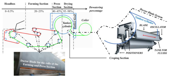
1], all of them provide for a continuous transformation process focused on the progressive drying of an entering pulp, the elimination of any polluting residues, and the achievement of wanted mechanical characteristics to be given to the final product. The entering pulp, made of about 99.5% water and 0.5% wood fibers, is continuously transformed into coils made of an evenly distributed thin layer of wood fibers, dewatered by about 95–98% by a sequence of thermo-mechanical operations carried out by specific devices [
4].
In a conventional TPM, an initial Headbox allows for collecting the diluted entering pulp, preventing the fiber flocculation, reducing the water by 0.5%, and moving the pulp into the next Forming Section. In the latter, a fiber-oriented paper web, placed on fabric moved by powered rolls, loses about 20–25% of water by natural drainage and by suction applied by vacuum systems. Subsequently, in the Press Section, the paper web loses about 40–45% of water by the pressure exerted by rolls covered by felt. The final loss of water, about 95–98%, occurs in the Drying Section where the paper web is wrapped around the Yankee cylinder. The evaporation of water is carried out by the steam-heated surface of the cylinder and a flow of air inside the hood around the cylinder. Finally, the resulting paper tissue is wrapped around the coiler, a powered roll whose rotation is stopped when the coil reaches the wanted diameter. Between the Drying and the Coiling Section, the Creping Section allows for the detaching of paper tissue from the dryer cylinder and the creation of a series of crepes on it.
Properties given to paper tissue mainly depend on the type of pulp [
2,
5,
6], the speed of rolls [
4], and the level of adhesion of the paper around the dryer cylinder [
7] and rolls. They must always be clean. Doctor Blades (DBs) [
8] scrape paper tissue off from the surface of the dryer cylinder and clean the surfaces of the rolls in the Forming and Press Sections. These are blades made of metal (steel, bronze) or carbon fibers [
9] that can be combined with a specially developed epoxy [
10] or water repellent material [
11] to facilitate the cleaning operation. For scraping paper tissue off, a DB is mounted and moved in two modes. If the DB is rigidly fixed to its support, a couple of hydraulic or pneumatic linear actuators move the support in order for the DB to approach and move away from the rolls [
12]. If the support is fixed, the DB is connected to the latter by two deformable pneumatic tubes, longitudinally mounted under the overall length of the DB and at the sides of the hinge [
13]; the alternatively radial expansion of the tubes, similar to that of pneumatic muscles [
14,
15] or air pockets actuators [
16,
17], rotates the DB around the hinge in order for the DB to approach and move away from the rolls.
For cleaning the rolls, a DB must be placed near to them and to the dryer cylinder; then, it must be moved forwards and backwards along the longitudinal direction of the rolls, perpendicular to the machine direction. Oscillation can be electro-mechanically, hydraulically, and pneumatically actuated [
18]. Pneumatic oscillators are the most widely used for their low cost and high power to weight ratio, and are suitable in environments with moisture or flammable materials such as in paper industry where the use of electrical components could be critical. Mounted on one side of the DB, two types of pneumatic solutions have been developed: a pneumatic rubber bellow, or more mounted in series, with a slide mechanism [
18,
19], and pneumatic cylinders [
20,
21,
22,
23]. The first is less suitable because of jerky oscillations and performances, and the consistency of the decline in rubber over time. The second is more reliable and efficient, with compact dimensions (length 120–200 mm; diameter 150–200 mm), strokes of up to 16 mm, a pressure range of 2–10 bar, exerted forces of up to 11 or 22 kN (by a double piston) at 6 bar, and a temperature range of up to 150–180 °C. As described in [
23], integrated at one end of the cylinder, a bi-stable 5/2 mechanically operated pilot valve controls the oscillatory motion; the mechanical command switch of the valve is carried out by a couple of thin metal levers directly mounted at the sides of the body; the rod of the cylinder provides for alternatively switching one of them at the end of the stroke according to the motion direction. This solution is effective, but in some practical applications the levers could be faulted for vibrational and fatigue phenomena.
Different to the existing commercial solutions, for a real industrial application a novel pneumatic oscillator was conceived and described in our study. It is made of a low-friction double-effect cylinder with a through-rod to be mounted on one end of the DB. The novel pneumatic oscillator is equipped with a more robust switching system. Precisely, the novelty of the proposed device is represented by the integration of two pneumatically powered limit switching valves in the two heads of the cylinder: the change in direction of the motion of the piston is controlled by a mono-stable 5/2 air-operated pilot valve mounted on one head of the cylinder and switched by the pneumatic signals coming from the two integrated valves. Each limit switch valve acts as a normally closed (NC) monostable 2/2 mechanically operated valve switched by the piston of the cylinder at the ends of the stroke. A smart pneumatic circuit ensures the function of the entire system; a single air inlet port provides a power supply to the oscillator, and a single one-way flow regulator acts as a speed controller, also for low speed values, avoiding the stick-slip phenomenon. In this paper, the application context is presented; then, the design and the working principle of the pneumatic oscillator is detailed; finally, the experimental activity carried out with a prototype of the limit switch valve and with the first prototype of the pneumatic oscillator is described and the results are reported and discussed.
2. Case Study Background
In a TPM, whose process was previously explained and is sketched in
Figure 1, DBs are mounted in correspondence with the rolls of the Forming and Press Sections and in the output region of the dryer cylinder, before the coiler. As shown in
Figure 1, paper web (green colored line) enters from the Headbox and is finally detached from the dryer cylinder by one DB or a set of DBs. Following the path of the paper web, the functions of DBs are:
To scrape and always maintain a clean surface of the rolls, removing any accumulation of material on them.
To maintain the same roughness of the surfaces of rolls.
To provide for creping the sheets of the paper in correspondence with the dryer cylinder.
To redirect the paper tissue towards the coiler.
According to the performances of a TPM, the overall number of blades can vary. For a dryer cylinder, more than one blade could be adopted, as shown in
Figure 1; in this case, the overall set of blades is called a DB System.
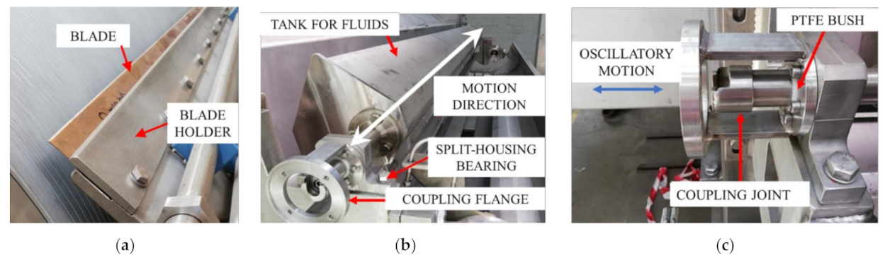
The development of the novel pneumatic oscillator described in the present paper was carried out to address a real industrial application: to replace in an industrial TPM all existing commercial pneumatic oscillators based on cylinders by a new one that is more compact, with no faults of the command switches of the pilot valve, with no minimal jerky oscillation, and resistant to a pressure of up to 10 bar and a temperature of up to 70 °C. A pneumatic oscillator must be applied to a set of DBs whose blades are fixed to supports equipped with a couple of pneumatic positioners (at both ends), to be moved to and from the rolls. Moreover, some DBs have a tank for collecting processing fluids that are responsible for a corrosive acidic environment with a high humidity rate. All DBs show the same assembly of blades: each blade, blocked by the blade holder (
Figure 2a), is mounted on a rigid frame by a couple of split-housing type bearings (
Figure 2b,c). Such types of bearing are necessary to easily remove and replace the bushes, which is described later, and to easily remove the blade. The blade holder is mounted on a shaft that can linearly move perpendicular to machine direction within two bushes made of PTFE (
Figure 2c) mounted inside the split-housing. The linear motion is an oscillatory motion to help the DB scrape the surfaces of the rolls. One end of the shaft (
Figure 2c) has a coupling joint to be connected to the moving rod of the pneumatic oscillator whose body must be fixed by four M12 screws to the coupling flange of the DB (
Figure 2b,c).
With the exception of the bushes, all components were made of stainless steel AISI 316 to be acid and water resistant. Although the type of blade for each roll is the same, their performances are different in terms of amplitude and frequency of the oscillatory motion; amplitude can vary in the range of 10–20 mm, frequency in the range of 1–10 cycles/min. Hence, considering the development of a single pneumatic oscillator to be adapted to each blade, it has to move at low adjustable speeds with a range of about 0.8–7 mm/s.
3. Design of the Pneumatic Oscillator
3.1. Technical Specifications
The developed pneumatic oscillator was achieved to be driven by a pneumatic cylinder. Obviously, due to low speed values, for a continuous and fluid motion the stick-slip phenomenon has to be avoided. For ease of replacement and maintenance, and for the convenience to manage only one device, the same type of pneumatic oscillator was decided to be adopted for all DBs.
To satisfy the requirements of the industrial process, the following technical specifications were defined:
To avoid the stick-slip phenomenon, a low-friction pneumatic cylinder, equipped with proper grease and seals, has to be adopted.
To ensure a continuous oscillatory motion, the oscillator has to operate autonomously. Hence, it must be equipped with a single air inlet port and change in motion direction must be controlled by an internal integrated adjustment system.
To ensure the full amplitude of the oscillatory motion, a stroke must be equal to 20 mm. For lower values of amplitude, internal spacers must be considered.
To adjust speed, or equivalently the frequency of the oscillatory motion, a flow regulator must be adopted in a proper design.
To withstand acid and humid environments, all outer components must be made of AISI 316.
The working temperature range of all components has to be 0–80 °C.
Hence, an SMC low-friction double-effect cylinder with a through-rod (bore 160 mm; stroke 20 mm; rod diameter 40 mm) was adopted for the development of the proposed pneumatic oscillator. The adopted bore dimension is the better choice for avoiding the stick-slip phenomenon at very low speeds; moreover, since the adopted cylinder has been widely used and tested until 10 bar, it could reach this maximum pressure value without mechanical and functional faults.
3.2. The Pneumatic Circuit
The aims of the pneumatic circuit were to ensure the oscillatory motion of the cylinder rod, to adjust the rod speed, and to avoid the stick-slip phenomenon. The first aim expects two alternative command signals for switching the pilot valve of the cylinder when forward and backward strokes are completed. The remaining aims can be satisfied by the adoption of flow regulators, properly mounted. Therefore, attention was focused on finding a suitable and reliable circuit for the first aim.
The adoption of the timed control pulses of the pilot valve was at the basis of a first solution: this expects a lower number of components (only some one-way flow regulators, in addition to the pilot valve) to be easily integrated onto the cylinder, and low production costs. On the contrary, it requires a more complex circuit, not easily adjusted. This solution was based on the resistance–capacitance circuit, made of the tubes of the circuit (capacitance) mounted in series to a flow regulator (resistance), whose behavior, according to a lumped parameters modelling and a step input, can be formulated as:
where
P1 is the output pressure of the resistance-capacitance circuit,
PIN is the input pressure of the flow regulator, t is the time,
R is the current resistance of the flow regulator depending on its internal passage section of the air flow, and
C is the constant capacitance, depending on the volumes of the tubes of the assembled pneumatic circuit [
24]. Equation (1) expresses the response of a first-order system where
RC is the time constant τ. By adjusting the value of
R, the achievement of a certain value of
P1 is delayed with respect to the occurrence of the input command value
PIN. The delay must be the time (t) necessary to complete one stroke.
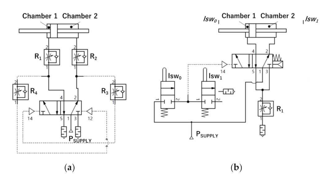
With reference to
Figure 3a, one-way flow regulators R
3 and R
4 were adopted to delay the time for switching the air-operated pilot valve. When the cylinder is leftward moving (right position of the valve is active), an air power signal is sent to the right chamber of the cylinder and to the air inlet port for the pneumatic switching of signal 14 to activate the left position of the valve. Depending on the throttling rate of R
3, the pressure value of signal 14 reaches the switching pressure value after a time (t) with respect to the occurrence of signal 12; when the valve is switched, the cylinder moves rightward and the line of signal 14 is connected to the exhaust. Depending on the throttling rate of R
4, signal 12 in turn reaches the switching pressure value after a time (t) with respect to the occurrence of signal 14; when it occurs, the motion direction changes and the line of signal 12 is connected to the exhaust. Flow regulators R
1 and R
2 were adopted as speed controllers. Bulky pneumatic timers were not considered. Only a single air inlet port was required. When a circuit is powered by P
SUPPLY, the cylinder moves according to the last position of the pilot valve and then autonomously oscillates. On the contrary, four manual regulations are required to adjust and synchronize delay and speed. Finally, experimentally checked, for symmetric behavior along the two strokes, particular attention must be given to the same throttling rate of the R
3 and R
4 couple and of the R
1 and R
2 couple, and to the length of the pneumatic lines, which must be equal.
To overcome these critical issues, a second solution was explored. This expects a simpler circuit that is easy to be adjusted and a higher number of components because two limit switch valves are required. The typical configuration with external limit switches was not considered for being too bulky; this requires a bi-stable 5/2 air-operated pilot valve with two separated command lines and two 3/2 mechanically operated switch valves. On the contrary, the conceived circuit adopted a mono-stable 5/2 air-operated pilot valve and two 2/2 mechanically operated switch valves both connected to the single air inlet command port of the pilot valve. With reference to
Figure 3b, the right stable position of the 5/2 pilot valve provided for the leftward moving of the cylinder. The single air inlet port was connected to the pilot valve and to the lsw
0 limit switch valve. When the latter was activated, it provided for switching the pilot valve by a positive pneumatic command for signal 14, and the cylinder moved rightward. Then, lsw
0 was deactivated. When lsw
1 was activated, it provided for a negative pneumatic command for signal 14, whose line was connected to the exhaust, and the pilot valve was switched by the internal spring: hence, the cylinder moved leftward. Both exhaust ports of the pilot valve were connected to a single one-way flow regulator that acted as a speed controller or as a frequency controller. In fact, frequency depends on the time required to cover the stroke of the cylinder; hence, it depends on the speed of the piston. Considering the volume flow rate exiting from the chamber of the cylinder that was connected to the exhaust, it can be demonstrated that the exhaust air flow increased as the exhaust resistance (R
1) decreased. Speed was in inverse proportion to the resistance introduced by R
1.
Only one easy regulation was required, as experimentally tested. The second circuit turned out to be more suitable and reliable.
3.3. The Mechanical Design
The designed pneumatic oscillator was made of a double-effect cylinder with a through-rod equipped with a limit switch valve integrated into each head of the cylinder. A section view of the pneumatic oscillator is shown in
Figure 4; the inner head is the one interfaced with the coupling flange of DBs and equipped with the single air inlet port of the cylinder; the outer head is equipped with the air-operated pilot valve and supports the tubes of the pneumatic circuit. The limit switches are alternatively activated by the piston, at the end of each stroke.
Since the double-effect cylinder with a through-rod is a commercial device, the mechanical design was mainly focused on the design of the limit switch valve and its integration into the heads of the cylinder.
As shown in
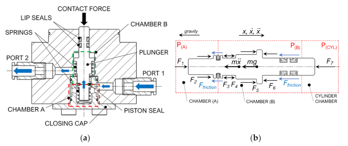
Figure 5a, a limit switch system consists of a plunger that moves inside a seat, to be obtained directly in the head of the cylinder. Actually, in the figure, a proper seat is represented, later described in
Section 4. Two steel springs, EN 10270-1 SH(C), mounted in parallel, kept the plunger in the resting position. Regardless of the head of the cylinder, the limit switch system acted as a mono-stable mechanically operated 2/2 NC valve. The plunger was equipped with two lip seals, which isolate the limit switch valve body from one of the chambers of the cylinder, and a piston seal, which isolates chamber A (the red one) from chamber B (the green one). Chamber A was made by the closing cap; inside it, the segment of the plunger that acts as a shutter between the chamber A and B moves. Chamber B is the volume in which the air flows as a result of the activation/switching of the system. The critical area of the system turns out to be the passage section of the fluid from chamber A to chamber B. This section must be opened whenever the piston touches the plunger for switching the pilot valve. The closing cap solves this problem; it is designed not only with the ultimate aim of hermetically closing the system, but also for making possible the change in the section diameter in the passage between chambers A and B. The piston seal makes it possible to occlude the passage when the plunger is at rest.
With reference to
Figure 5a, when the piston applies the contact force on the plunger, the latter moves downward and the passage of air takes place from chamber A to chamber B, or equivalently from Port 1 to Port 2; when the contact force is null, springs move upward in the plunger and the passage of air from chamber A to chamber B is forbidden. As for the inner limit switch, chamber A is connected to the main power supply line, and chamber B to the command line of the pilot valve and chamber A of the outer limit switch; as for the latter, chamber B is connected to the external environment for the exhaust of the command line of the pilot valve.
The size of the body of the limit switch valve and springs depended on the consideration that the plunger protrudes by a length equal to 4.5 mm in the cylinder chamber, whose pressure changes from zero to the supply pressure of the cylinder.
In the free body diagram of the plunger, shown in
Figure 5b, the values of the forces (
Fi) depend on the pressure values (P) in three distinguishable chambers of the limit switch system. Certainly,
F2 and
F5 also depend on the elastic constants of the springs and the displacement of the plunger.
Table 1 reports the pressure values for the inner and the outer limit switch systems.
In both limit switches, F3 and F4 were self-balancing: they were equal and opposite. F6 contributed to the transient switching of the inner limit switch and was null on the outer one. For the plunger to return to the resting position, the best condition occurred in the inner head, where the contribution of pressure in chamber A of the inner limit switch, in addition to the elastic forces of springs, always facilitated the return.
On the contrary, the critical condition occurred in the outer head, when the outer limit switch was activated. In such a condition, the command branch was unloaded, and chambers A and B of the outer limit switch were at zero relative pressure; the piston moved downward and the compressed air was fed into the cylinder chamber at the operative pressure. Since the diameter of the segment of the plunger that was immersed in the chamber of the cylinder was equal to 6 mm (area equal to 28.27 mm
2), the occurring pushing force
F7 depended on the values of pressure in the chamber of the cylinder, as reported in
Table 2.
In such a condition, the plunger did not receive any contribution from the internal pressure in chambers A and B (F1 was null), and the return to the resting position depended only on the force exerted by the springs. Considering the friction force (Ffriction) that was acting on the seals and the operative pressure equal to 7.0 bar, the force of the springs (F1) must be at least equal to 25 N to be safe and to allow both plungers to come back to their resting position, and to avoid an unintended activation of the limit switch system due to the force exerted by the pressure in the chambers of the cylinder.
As for the constructive aspects, all outer surfaces of the cylinder were made in AISI 316; to avoid all components being made of stainless steel, it was thought to apply a watertight protective casing. The inner head was also made of AISI 316, as well as the rod and accessories coupled to the blade to be moved.
3.4. The Working Principle
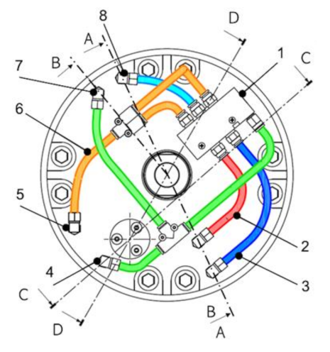
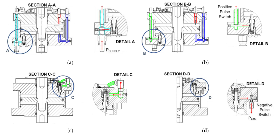
The developed oscillator acted as a fully autonomous pneumatic handling device by the integration of the pneumatic circuit shown in
Figure 3b. The connection of the single air inlet port to the main power air line caused the oscillatory motion to move cyclically and continuously, without further intervention. The speed of the oscillator was adjusted by the rotation of the one-way flow regulator pin integrated into it. Moreover, the adjustment system was integrated into the cylinder through a combination of internal and external ducts. As shown in
Figure 6, the main branches of the pneumatic circuit were identified by different colors:
In cyan, the power supply branch of the pilot valve;
In red, the supply/unloading branch of chamber 1 of the cylinder (see
Figure 4);
In blue, the supply/unloading branch of chamber 2 of the cylinder (see
Figure 4);
In green, the control branch that moves the switching pulses generated by the integrated limit switch valves;
In orange, the exhaust branches of chambers 1 and 2 connected to the one-way flow regulator.
With reference to the section lines and to the colors of the branches of the pneumatic circuit of
Figure 6, the working principle of the pneumatic oscillator was the following:
4. Experimental Activity
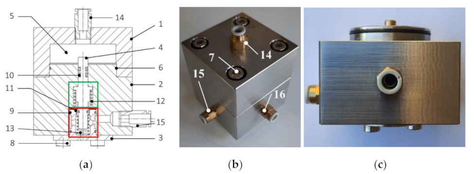
Since the main component of the pneumatic oscillator is the integrated limit switch system, one prototype of it was made. With reference to the explanation in
Section 3.3 and to
Figure 8, the prototype was conceived to be made of four main components: upper block (1), body of the valve (2), closing cap (3), and plunger (4). The volume (5) between the upper block and the body of the valve simulated the pressurized chamber of the cylinder. The static seal (6) ensured the pneumatic seal between (1) and (2). Four screws (7) provided for the assembly of (1) to (2). The closing cap was mounted by four 90° spaced screws (8) to the lower surface of the body of the valve. Two static seals (9) ensured the pneumatic seal between the closing cap and the body of the valve.
The plunger was equipped with two dynamic lip seals (10) and an O-ring dynamic seal (11) to ensure the pneumatic seal between volume (5) and chamber B (the green one) and between chamber B and chamber A (the red one), respectively. The downward motion of the plunger was due to the force exerted by the pressure acting on the upper surface of the plunger (28.26 mm2 area); the upward motion was provided by two springs, (12) and (13), mounted in parallel. The plunger stuck out of the body of the valve by 4.5 mm. One fitting (14) (6 mm external tube diameter) was mounted on the upper surface of the upper block for air inlet/outlet in volume (5); two of the same fittings (15 and 16) were mounted on the body of the valve to create the power supply port and the switching of the pilot valve port, respectively.
The experimental activity was focused on the characterization and functional validation of the prototype of the limit switch system and the first prototype of the pneumatic oscillator, as follows.
4.1. Check of the Pneumatic Seal
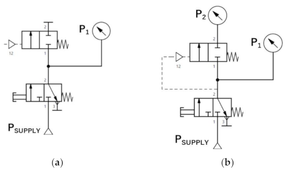
To measure any air leaks occurring in chambers A and B, two tests were carried out by the pneumatic circuits shown in
Figure 9, where the mono-stable 2/2 piloted pneumatic valve represented the prototype; the pneumatic pilot command was required in the volume of the interior chamber to move the plunger that acted as a spool. In both tests, the P
SUPPLY value was set equal to 7.0 bar, the maximum operative pressure value estimated for the pneumatic oscillator. Bourdon type manometers (f.s. 10 bar, resolution 0.10 bar) were adopted for pressure measurements.
In the first test (
Figure 9a) to validate the pneumatic seal of chamber A, the 3/2 valve was released when pressure P
1 in the isolated chamber A reached P
SUPPLY value. Then, for a time period equal to 24 h, the pressure value was monitored.
In the second test (
Figure 9b) to validate the pneumatic seal of chamber B, the 3/2 valve was released when pressure values P
1 and P
2 reached P
SUPPLY value. Then, for a time period equal to 24 h, both pressure values, initially equal, were monitored.
No air leaks were recorded in both tests: pressure values remained constant during the time of observation. The choice of the adopted rubber seals and the dimensioning of the hole of the plunger were satisfactory validated.
4.2. Measurement of the Necessary Stroke of the Plunger
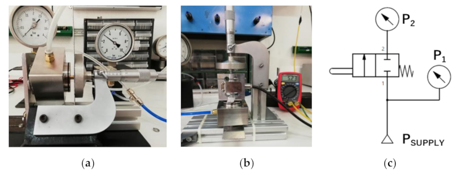
A test was carried out to achieve the minimum value of the stroke of the plunger necessary for the air passage through the two chambers. The prototype, without the upper block, was horizontally mounted on a frame made of a commercial aluminum profile and an iron support of a micrometer (resolution 0.02 mm), as shown in
Figure 10a. The lower surface of the body of the valve was fixed on the frame; an aluminum plate, mounted at the end of the moving rod of the micrometer, was placed in contact with the upper surface of the plunger. The aluminum plate moved parallel to the plunger. The pneumatic circuit shown in
Figure 10c was adopted. The leftward motion of the moving rod provided for the motion of the plunger. The P
SUPPLY value was set equal to 2.0 bar, higher than the operative switching pressure of the pilot valve. Starting from the plunger at rest, by the adjustment of the micrometer P2 was monitored until it differed from its initial zero value, reaching P
1 value. The test was repeated 30 times.
The achieved minimum stroke was 2.25 ± 0.02 mm, quite in accordance with 2.30 mm as imposed in the mechanical design.
4.3. Measurement of the Switching Force
A test was carried out to achieve the minimum value of the force necessary for the switching of the 2/2 valve. The prototype, without the upper block, was vertically mounted on a frame made of commercial aluminum profiles. A load cell (TCA AEP Transducers, f.s. 10 kg, sensitivity 2 mV/V) was adopted. As shown in
Figure 10b, the load cell was mounted between the higher surface of the plunger and the aluminum plate of the micrometer. During the assembly of the test bed, particular attention was given to ensure coaxiality among the plunger, the axis of the moving road of the micrometer, and the load direction. The same pneumatic circuit of
Figure 10c was adopted. The P
SUPPLY value was set equal to 2.0 bar. The adjustment of the micrometer provided for the load application and the plunger motion. The switching force was measured as the force value corresponding to the instant in which P
2 differed from a zero value, reaching P
1 value. A multimeter, used for measuring the output signal of the load cell (range 0–10 Vdc), completed the testbed. The test was repeated 30 times.
The achieved switching force was 55 ± 0.3 N. Such a result allowed for performing an indirect measurement of the friction force among the seals and the body of the valve. As expected by the mechanical design, the force required for moving the plunger by 2.3 mm, as imposed in the mechanical design, was equal to 38.57 N, being the sum of 25 N of preload and 13.57 N to compress the springs (2.3 mm for an equivalent elastic constant K equal to 5.9 N/mm). Moreover, the switching force depended on an additional 10 N, the opposing pushing force exerted by the pressure (equal to 2.0 bar) on the lower surface of the plunger being equal to 50.24 mm2. Hence, the overall expected force was 48.57 N. The gap with respect to the measured switching force (55 N) was represented by the friction force, equal to about 6.5 N.
4.4. Achievement of the Flow Characteristics
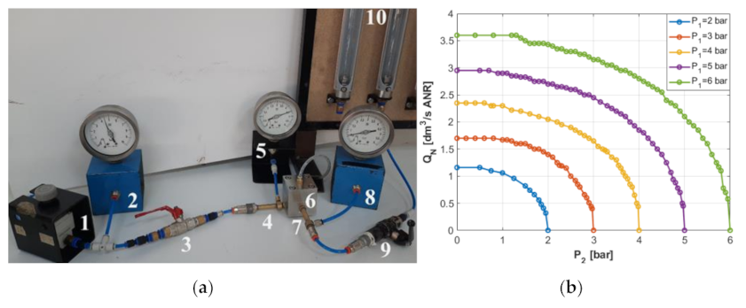
The testbed shown in
Figure 11a was assembled according to the ISO 6358 Standard [
25]. It required that, for a given P
1, the volume flow rate Q
N of air at standard reference atmosphere passing through the valve must be reported as a function of P
2, where P
1 and P
2 are the absolute pressure values at the inlet and outlet ports of the valve under test, respectively. Tests were carried out for five values of P
1 (2.0, 3.0, 4.0, 5.0, and 6.0 bar), according to the requirement of the Standard. Two asameters (ASA E5 2600/H) with different measurement ranges (0.12–1.2 dm
3/s ANR; 0.5–5 dm
3/s ANR) were adopted for the flow rate measurements, according to the different values of P
1.
Figure 11b shows the typical behavior of the volume flow rate curves: the increase in P
1 expects an increase in
QN, whose value is equal to zero when
P1 is equal to
P2 (no flow rate occurs for a null pressure difference). Moreover, starting from the null value of
QN, all the achieved curves can be divided into two sections: a first curved section in which the air flow is subsonic and the flow rate increases as the pressure difference increases, and a second straight section in which the air flow is sonic and the flow rate is constant, independent of the pressure difference. The value of
P2 between the two sections is called P
2 critical (
P2cr).
From the test results, two flow rate characteristics that describe the performance of the valve were achieved, the critical back-pressure ratio (b) and the conductance (C), that measure the ability of a pneumatic valve to conduct the air flow.
The first is expressed as:
The second is expressed as:
Obtained by the formulation defined by the Standard:
Furthermore:
where
QN and
QNMAX are the volume flow rate of the air along the curved section (
P2cr <
P2 <
P1) and the straight section (
P2 <
P2cr), respectively;
is a coefficient to take into account the temperature
T1 of the air during the test, measured in Kelvin degrees; and
, which is the pressure ratio.
Achieved values are reported in
Table 3.
Average values of b and C were 0.25 and 0.44, respectively, in accordance with the values of the pneumatic valves with similar dimensions produced and distributed by SMC Corporation.
4.5. Functional Test of the Working Principle
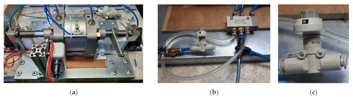
The first prototype of the pneumatic oscillator was assembled to check the functionality of the working principle. As shown in
Figure 12a, it was made of a standard C95 Ø160 mm low-friction cylinder equipped with the components shown in
Figure 3b. The adopted 5/2 pilot valve and the speed controller (one-way flow regulator), shown in
Figure 12b,c, were both to be applied in the final industrial pneumatic oscillator. The length and section of the pneumatic line respected the requirements of the desired final product. Limit switch valves were not integrated in the heads of the cylinder; on the contrary, two prototype, previously described, were mounted as two external limit switches, switched by the surfaces at the tips of the rod. A stroke was imposed equal to 12 mm. A wire linear position transducer (Celesco DV301-0020-111-1110, f.s. 508 mm, sensitivity 1.80315 mv/V/mm) was mounted in parallel to the rod for measurements of piston positions as a function of time. A DAQ board NI USB6001 was adopted for acquiring the output voltage signals of the position transducer.
A first set of activations of the pneumatic oscillator were carried out; regardless of the current value of the stroke, the piston always started to autonomously move when a power supply was given to the pilot valve.
In a set of continuous motions of the piston, both limit switches allowed for a proper switching of the pilot valve without a lack of command signals.
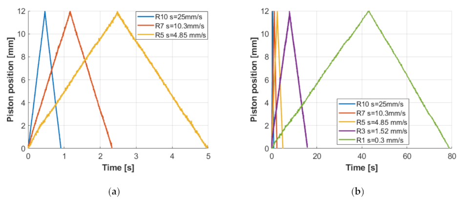
Finally, speed measurements and a monitoring of the piston position as a function of time were carried out according to several resistance configurations of the speed controller and in the absence of an external load. Each discrete resistance adjustment (R) was imposed by moving the knob of the flow regulator on a fixed number (
Figure 12c) in the range of 1–10 (R1 meaning highest resistance; R10, meaning lowest). The results are reported in
Figure 13.
Figure 13 shows the effect of resistance on the speed value; moreover, it can be noticed that the motion of the piston was always fluid and continuous, without stick-slip occurrence. This was further verified at the lowest value of speed which was estimated equal to 0.3 mm/s, lower than the required one according to the technical specifications.
Such encouraging results validated the working principle of the conceived pneumatic oscillator.
5. Conclusions
The Doctor Blade is a device adopted to scrape the outer surfaces of the rolls of a tissue paper machine. The scraping action calls for an oscillatory forward and backward motion of the blade of the Doctor Blade along the longitudinal direction of the rolls and perpendicular to the machine direction. Several types of devices, called oscillators, are commercially available. In the present work, in order to address a real industrial application a novel pneumatic oscillator was presented. It was made of a low-friction double-effect cylinder with a through-rod equipped with two limit switch valves, each integrated into one head of the cylinder. The mono-stable air-operated 5/2 pilot valve was integrated into one of the heads of the cylinder: one limit switch valve allowed for a positive switching command of the pilot valve, the other for a negative one. A proper pneumatic circuit was presented, to be made of a combination of internal and external ducts. The presented activity was mainly focused on the design and the development of the limit switch valve. It acts as a mono-stable mechanically operated, normally closed 2/2 pneumatic valve. An internal plunger, subjected to the contact force of the piston, to the force of a couple of springs mounted in parallel, and to the force exerted by pressure signals, moves like a shutter in a proper seat, to be realized in each head of the cylinder. A prototype of the limit switch valve was made and experimentally tested; no air leaks were reported among its internal chambers. The switching force was equal to about 55 N; the minimum switching stroke of the plunger was equal to about 2.25 mm. The values of the flow characteristics of such a valve, the critical back-pressure ratio (b) and the conductance (C) are in accordance with the values of valves with similar dimensions. Functional tests carried out with the first prototype of the pneumatic oscillator provided encouraging results. The effectiveness of the proposed solution and the technical feasibility of the conceived device were validated; the absence of stick-slip during the oscillatory motion at low speed was checked. The prototype, whose limit switches were not integrated into the heads of the cylinder, satisfied the technical specification. The next step will be the construction of the final industrial product to be experimentally tested and mounted on a real industrial tissue paper machine.


 ,
, 


