1. Introduction
In order to meet increasing resource and productivity demands, modern technology requires the development of sustainable and responsible manufacturing processes. This leads to higher expectations in terms of component performance as well as durability [
1]. Both are especially impacted by surface friction, which decreases the performance through energy loss and the durability through material wear. Friction between surface pairings is mainly influenced by their respective surface roughness, with high roughness leading to high friction, heat generation, and wear. However, the absence of surface roughness may also lead to a loss of retaining volumes for lubricant fluids. Therefore, surface finishing technologies no longer target total roughness reduction, but instead the ability to manufacture specialized surface textures for given tasks, even partially maintaining topography features. This enables, for example, the utilization of existing roughness valleys for lubricant retainment while only removing roughness peaks to further decrease surface friction.
Exemplary applications which require low surface roughness and high durability under frequent and selectively large pressures are artificial dentures or hip joints made of ceramic materials such as zirconium dioxide (ZrO
2) [
2,
3]. Ceramics are distinguished by high hardness, heat and wear resistance, and bio-compatibility [
4]. Nonetheless, their generally low heat conductivity, high brittleness, and predisposition towards fracture formation make the machining of ceramics particularly challenging [
5]. After the sintering, ceramics are typically brought into final shape by microcutting or microgrinding processes, both of which may lead to local surface defects and high surface roughness. Despite the relatively ductile machining characteristics of ZrO
2 compared to those of other types of ceramics, Fook and Riemer observed “brittle intercrystalline breakouts” as well as ductile deformation bulges while describing ground ZrO
2 surfaces [
6]. These features likely affect the surface roughness adversely.
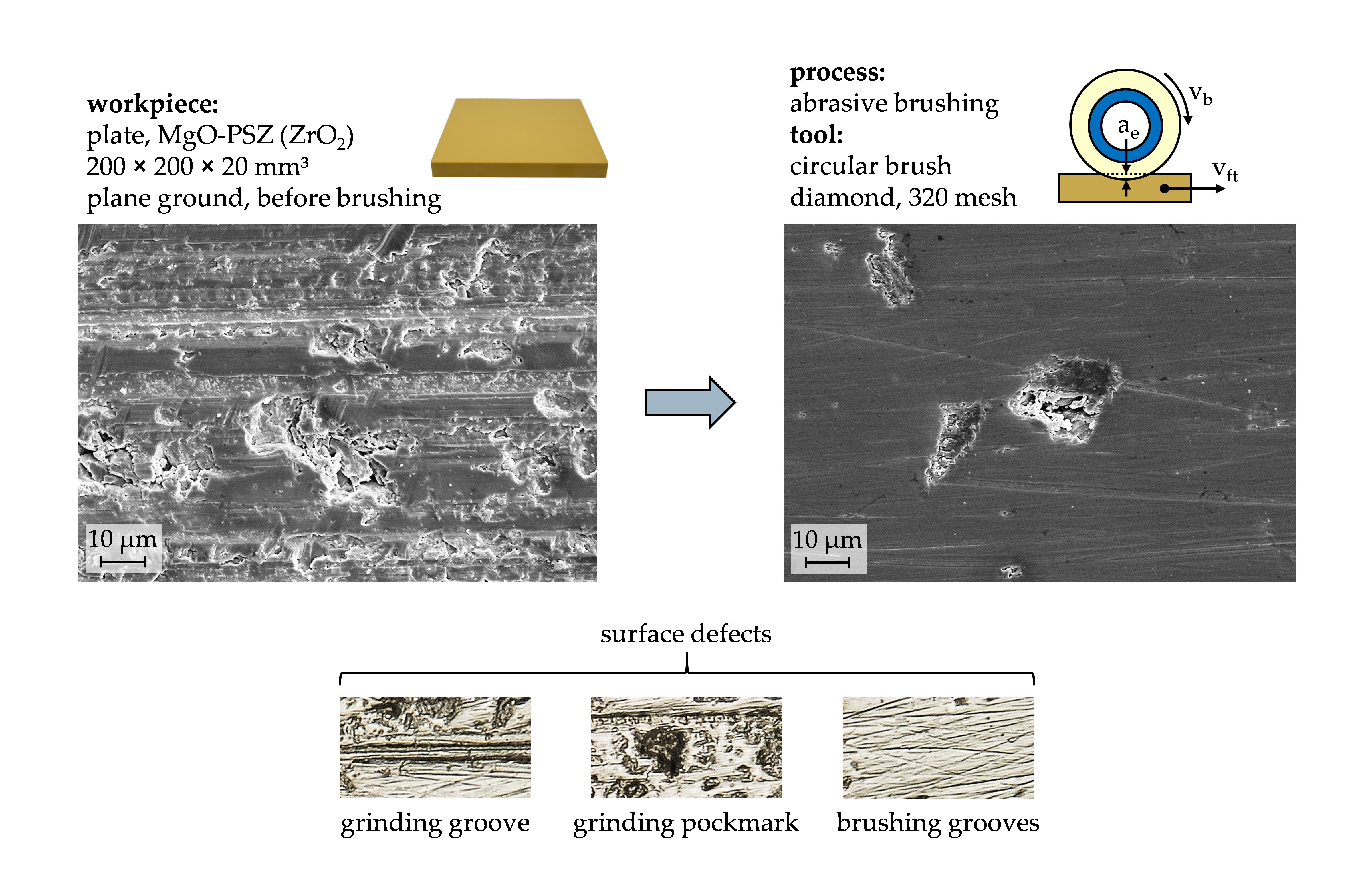
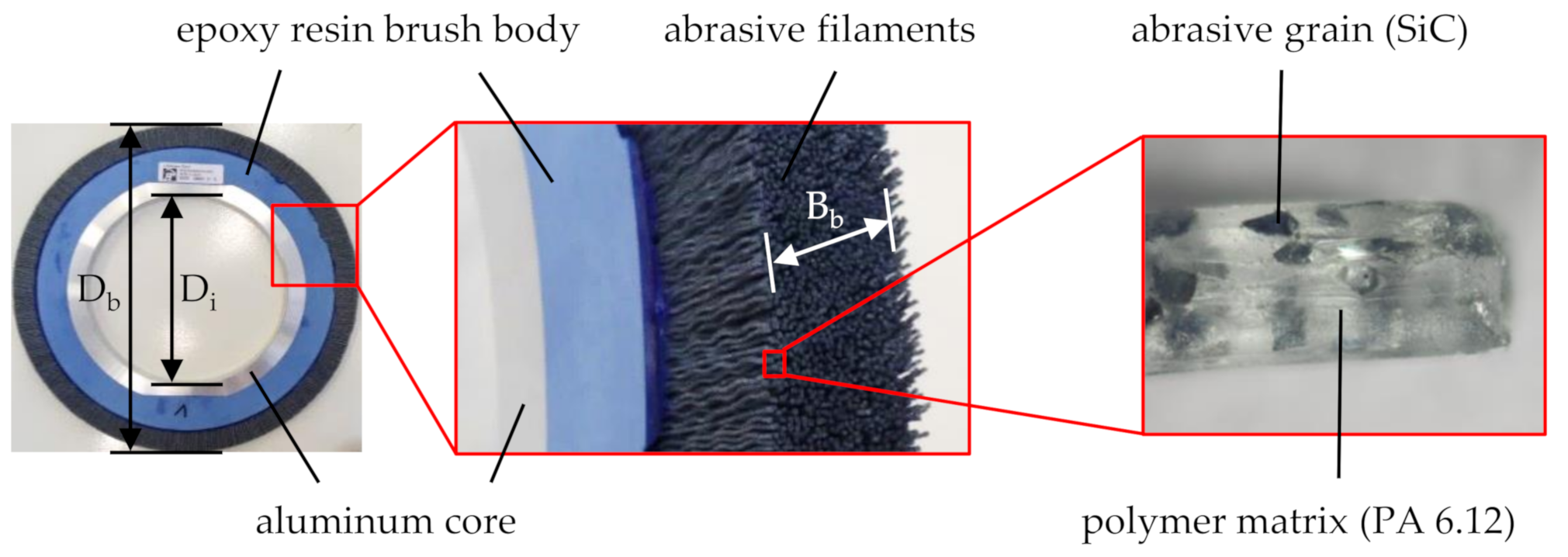
One machining process, which may be used for the finishing of components with hard surfaces, is brushing with bonded abrasives, making use of circular abrasive brushing tools (
Figure 1). During tool production, abrasive grains are bonded in a filamentary polymer matrix by an extrusion process [
7]. Common grain types are silicon carbide (SiC) and the softer aluminum oxide (Al
2O
3), although the finishing of ceramic materials suggests the use of harder grains such as polycrystalline diamond (PCD). As a polymer matrix, polyamide (PA) is most popular due to its high abrasion resistance, strength, as well as chemical inertness. Its thermal stability can further be increased by augmentation with additives [
8]. The extruded abrasive filaments are cut to length and then attached to a circular brush body by either bonding or stuffing. However, largest filament quantities can be achieved by casting an epoxy resin brush body into a mold after arranging the filaments in a circular fashion. The thereby achieved high denseness of abrasive filaments allows for a high tool stiffness, increasing the productivity [
7].
Among the potentials of brushing with bonded abrasives are low process forces and temperatures as well as the utilization of existing machine systems, such as industrial robots, grinding machines, or mills [
1,
7]. Furthermore, the high flexibility of the abrasive filaments causes them to deflect during contact with a workpiece, thus assuming its shape and compensating minor inaccuracies regarding the geometry of workpiece, tool, and path [
10]. Tool wear leads to a slow but successive shortening of the abrasive filaments [
8,
11,
12], until the filaments become too short and therefore too stiff in order to yield consistent processing results. In addition, brushing tools typically require an initial conditioning process to achieve approximately equal filament lengths, which may be time- and cost-intensive, depending on the characteristics of the brushing tool and the requirements of the brushing process.
While abrasive brushing is widely used in industries, process designs are generally based on empirical values. This is mainly attributed to insufficient knowledge of the complex movement behavior of the flexible filaments, complicating the prediction of process characteristics, processing results, and tool wear. Thus, the technological investigations discussed in this article are directed at the gain of knowledge of brushing ceramics with bonded abrasives, specifically the characteristics of brushed surfaces in regard to relevant tool specification and process parameters.
2. Materials and Methods
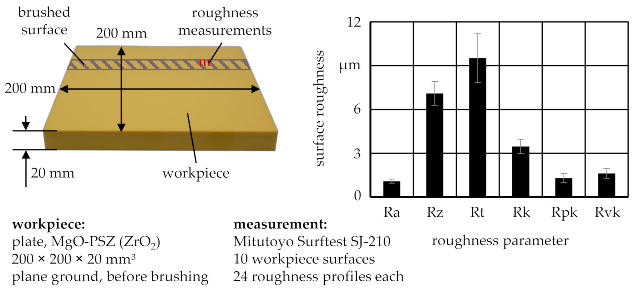
To gain a basic understanding of the mechanisms being effective while processing ceramic surfaces with abrasive brushing tools, experiments were conducted on rectangular ZrO
2 workpieces of the type Frialit FZM, manufactured and ground to dimensions of 200 × 200 × 20 mm
3 by FRIATEC AG, Mannheim, Germany. The sintered ZrO
2 matrix was partially stabilized (PSZ) with magnesium oxide (MgO) to strengthen the material by retaining cubic fluorite crystal structures—usually only present at temperatures T of >2300 °C—and thus prevented monoclinic crystal formation, which would lessen the fracture toughness [
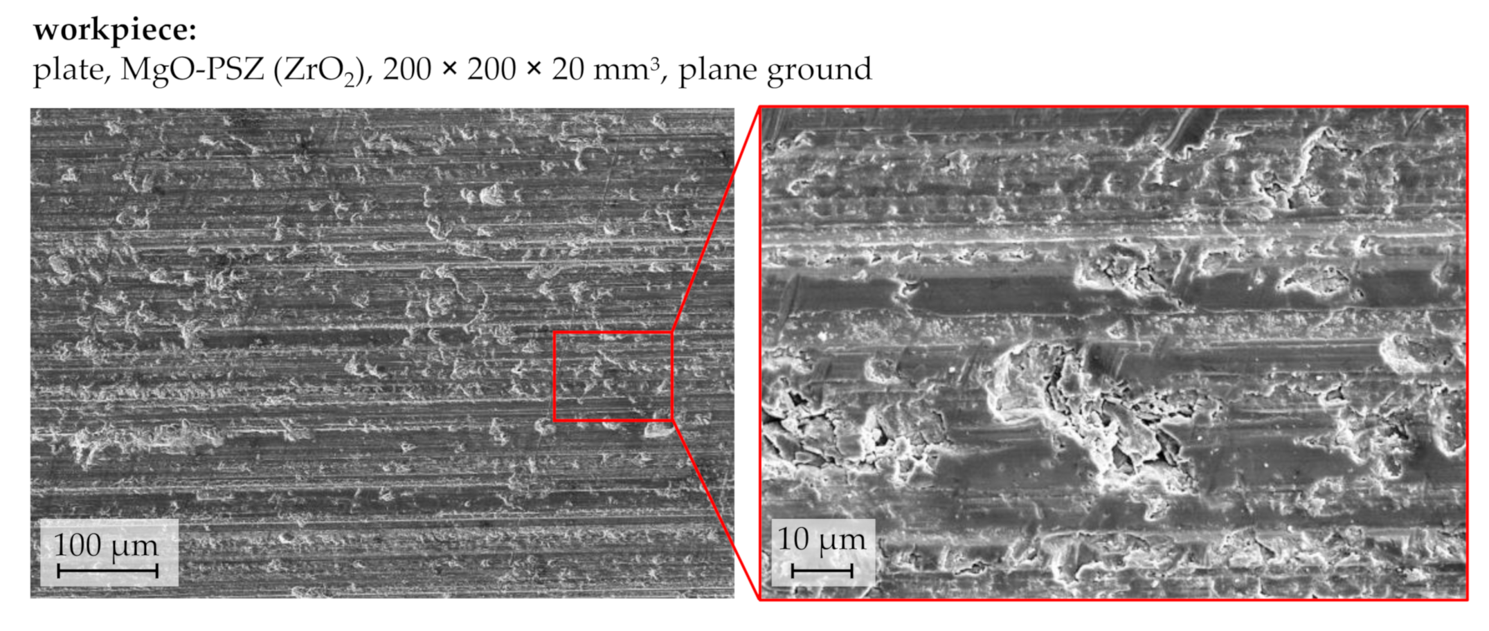
4]. Through a conventional plane grinding process, the surface roughness was then reduced to an arithmetic mean deviation of the roughness profile of Ra = 1.1 µm (
Figure 2), with all roughness measurements taken orthogonally to the grinding direction.
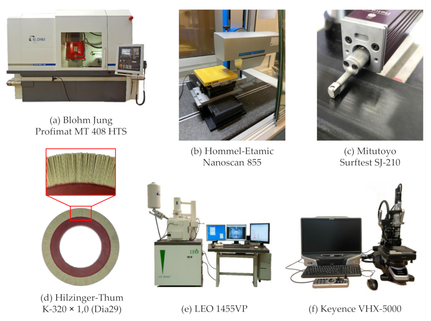
The circular brushing tools were manufactured by C. Hilzinger-Thum Gmbh, Sindelfingen, Germany (
Figure 3d). The tools featured an epoxy resin brush body with an outer diameter of D
b = 360 mm, an inner diameter of D
i = 203.2 mm, and a width of B
b = 20 mm, holding abrasive filaments with PCD grains bonded in a PA 6.12 matrix. Varied specification parameters include the grain size s
g and the filament diameter d
f. While the filament length l
f also impacts the processing results, too short filaments are prone to take thermal damage due to the high stiffness and the low heat conductivity of ceramic workpieces, as the filament plastic matrix has a relatively low melting temperature of T
m ≈ 150 °C [
8,
13] and requires heat losses to be absorbed almost entirely by the workpiece. The accidental melting of the abrasive filaments can be compensated by the use of cooling lubricant [
13]. However, PA 6.12 has a high tendency to absorb liquids, which decreases the filament stiffness and influences the consistency of processing results [
9]. Therefore, no cooling lubricant was used during the technological investigations and a filament length l
f = 40 mm was chosen for all experiments, although further research needs to be done on both cooling lubricants and appropriate filament lengths l
f for the surface finishing of ZrO
2.
The technological investigations were carried out on a plane and profile grinding machine of the type Profimat MT 408 HTS, manufactured by Blohm Jung GmbH, Hamburg, Germany (
Figure 3a). It was equipped with three linear axes, the encoders of which allowed for a positioning accuracy of approximately 1 µm. The spindle had a maximum performance of P
max = 45 kW and a maximum rotational speed of n
max = 11,000 min
−1. All workpieces were brushed in parallel to the direction of the preceding grinding process.
Before conducting the technological investigations, the machine tool was used to condition the brushing tools by shortening the filaments to approximately equal lengths l
f. As shearing off protruding filament tips with a sharp edge is a fast, yet imprecise method, a grindstone was used instead. After the radial runout error ∆D
b of the brushing tool fell below 0.4 mm, 0.11% of the brushing tool diameter D
b, an initialization process was repeatedly run with a brushing velocity of v
b = 20 m/s, a feed velocity of v
ft = 200 mm/min, and a penetration depth of a
e = 1 mm, hereinafter referred to as standard process parameters, until the reduction of the surface roughness did not significantly change any more, indicating quasi-static material removal behavior, which was required for consistent and comparable processing results. Subsequent experiments were conducted to determine the influence of the process parameters brushing velocity v
b, feed velocity v
ft, and penetration depth a
e on the workpiece surface roughness (
Table 1), as well as the workpiece form deviation, especially after successive brushing cycles.
Before and after individual brushing cycles, the workpiece profile depth h was measured orthogonally to the brushing direction with a laser triangulator of the type optoNCDT ILD2300-2 by the manufacturer Micro-Epsilon Messtechnik Gmbh & Co. KG, Ortenburg, Germany. The sensor had a measurement range of 2 mm and was operated at a measurement frequency of f
m = 1.5 kHz and a measurement feed velocity of v
m = 100 mm/min occurring orthogonally to the brushing direction. The vertical resolution of the sensor was denoted by the manufacturer as 0.03 µm at a reference measurement frequency of f
m = 20 kHz and should analogously be smaller for lower measurement frequencies f
m. The manual fitting and subtraction of the pre-brushing profile h
0 from the post-brushing profile h
1 provided information on the material removal depth h
r. The workpiece surface roughness was determined with a tactile instrument of the type Surftest SJ-210, manufactured by Mitutoyo Corporation, Sakado, Japan (
Figure 3c). Furthermore, the workpiece topography was measured with a tactile surface measurement device of the type Nanoscan 855, manufactured by Hommel-Etamic GmbH, Villingen-Schwenningen, Germany (
Figure 3b). Additionally, light microscopies were made with a microscope of the type VHX 5000, manufactured by Keyence Deutschland Gmbh, Neu-Isenburg, Germany (
Figure 3f). The images were taken with a 500× magnification, with a high dynamic range (HDR) enabled, and in 3D mode in order to increase the depth of focus. Scanning electron microscopy (SEM) images were obtained with a microscope of type LEO 1455VP, manufactured by Carl Zeiss AG, Oberkochen, Germany (
Figure 3e). For the evaluation of the material removal depth h
r and the workpiece topography, the software MATLAB R2019b by The Mathworks INC., Natick, MA, USA was used.
3. Results
3.1. Ground Surface Characteristics
Characterizing the surface of the ground workpieces on the basis of SEM images (
Figure 4), two prominent features became apparent: Firstly, the unidirectional grooves of the preceding plane grinding process stood out, discernable as parallel lines from left to right, and the breadth and occurrence of which depends predominantly on grain size and grain distribution in the grinding tool. Secondly, the plane ground surface was scarred with unevenly spread pockmarks of various sizes and shapes. Their approximate depths could not be determined based on SEM images but are suspected to be larger than those of the unidirectional grinding grooves. Equally unclear is whether the pockmarks were caused solely by the plane grinding process or originated from the workpiece composition and sintering. The comparison with workpieces from the same batch, which were lapped instead of plane ground, showed similar pockmarks and therefore suggests that they might be induced prior to the grinding process and then exposed by it, likely due to inhomogeneous crystal formation.
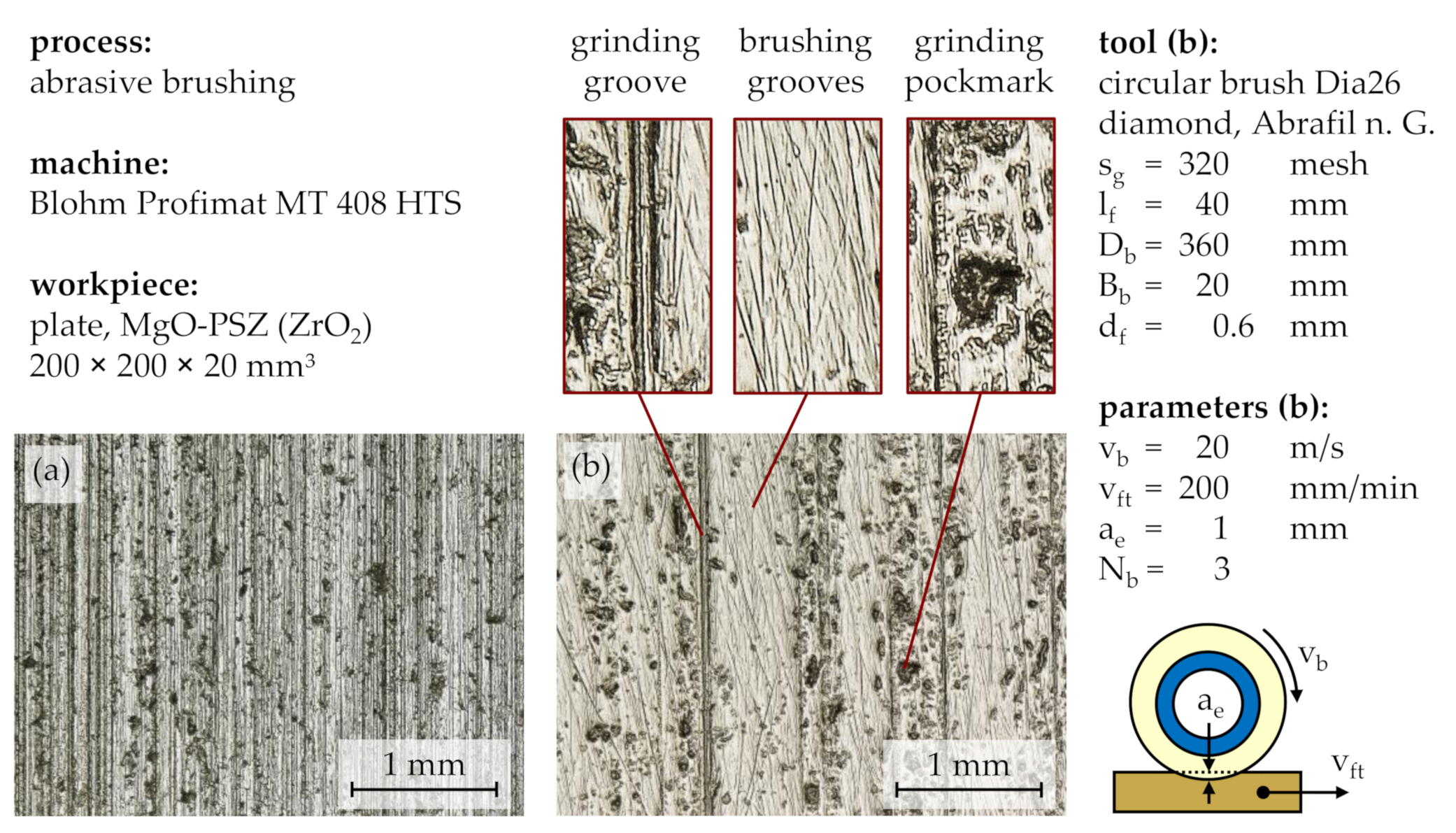
The characteristic unidirectional grinding grooves and nonuniform pockmarks can also be observed on the light microscopy images (
Figure 5a). The comparison with a gently brushed surface showed that both features can be partially removed by the abrasive filaments and replaced with multidirectional brushing grooves, which were thinner and shallower than the initial grinding grooves (
Figure 5b).
As surface defects such as grooves and pockmarks are prone to form fractures and thus weaken the material, especially in brittle materials such as ceramics [
4], their removal can increase the component durability. Considering medical engineering as the most important field of application for ZrO
2, pockmarks and other pitted blemishes in artificial dentures may lead to perpetual deposits of food debris and hence should be avoided. Similarly, rough surfaces possess a larger surface area and therefore increase bacteria accumulation [
14].
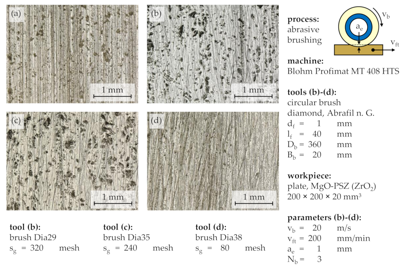
3.2. Tool Specification
Tool specification parameters, which influence the processing result, are mainly the grain size s
g, the filament diameter d
f, and the filament length l
f. While large grain sizes s
g generally lead to higher material removal rates, lower surface roughness can be achieved with small grain sizes s
g [
12,
15]. Therefore, the processing results for three different grain sizes s
g were compared: s
g = 320 mesh (29.2 µm), s
g = 240 mesh (44.5 µm), and s
g = 80 mesh (185 µm) [
16,
17] (
Figure 6). Operated at standard process parameters, after a number of brushing cycles N
b = 3, the processing results of the tools with relatively fine grain sizes of s
g = 320 mesh and s
g = 240 mesh appeared similar, with unidirectional grinding grooves replaced to some extent by multidirectional brushing grooves and pockmarks being exposed rather than removed. However, the comparison with a coarse grain size of s
g = 80 mesh showed that all unidirectional grinding grooves and most pockmarks were replaced by multidirectional brushing grooves, which were wider and seemed deeper than the brushing grooves created with smaller grain sizes s
g.
As light microscopy images are only suitable for a qualitative analysis of the processing result, the workpiece topography was furthermore measured with a tactile instrument before and after brushing. Due to the assumed axial symmetry of the brushed profiles, the measurement tip was placed in a reproducible position near the center of each brushed profile and moved outwards in axial direction xm. The measured surface comprised a projected area with a length in the axial direction of xm = 10 mm and a width in the feed direction of ym = 4 mm. This led to a total of 41 roughness profiles per brushed surface and a 0.1 mm distance between single roughness profiles.
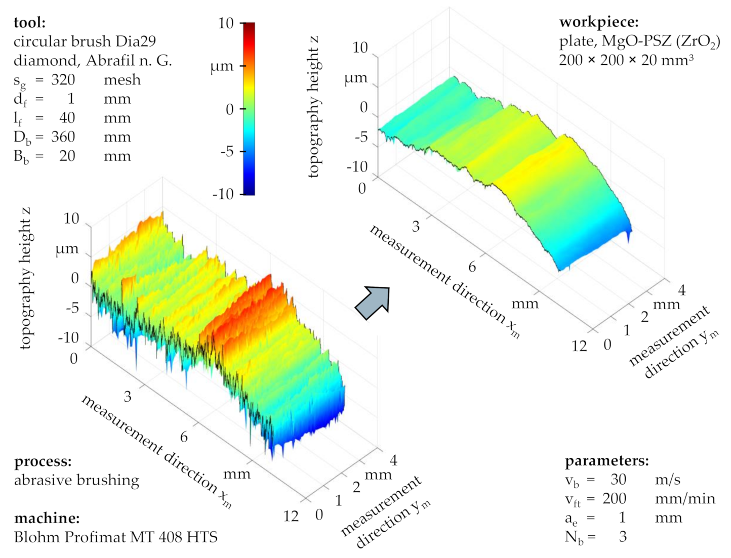
Considering the topographies before and after brushing with a grain size of s
g = 320 mesh and standard process parameters (
Figure 7), a preservation of the workpiece waviness can be observed alongside with an alteration of the surface roughness, characterized by the retaining of roughness valleys and the removal of roughness peaks. This suggested that successive abrasive brushing with fine grains subjected to a force-controlled principle allowed for the surface finishing of ZrO
2 without the formation of entirely new surfaces, as would be the case for similar finishing processes such as fine grinding or lapping, subjected to position-controlled principles.
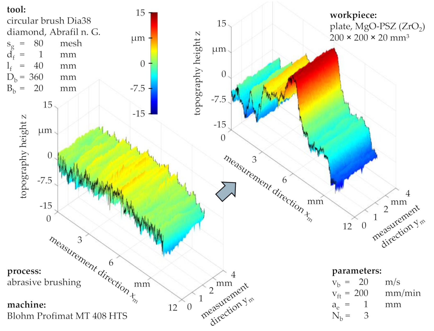
The comparison between the topography of a workpiece brushed with fine grains with a size of s
g = 320 mesh (
Figure 7) and the one which was also brushed with standard process parameters but with coarse grains with a size of s
g = 80 mesh (
Figure 8) suggested that the material removal mechanisms strongly depended on the grain size s
g.
Whereas fine grains altered the workpiece topography only slightly, coarse grains led to a large form deviation, exceeding the total height of the initial roughness profile and forming a new topography with arbitrary-form peaks and valleys. Depending on the application, this might affect the workpiece quality and functionality more than the presence of pockmarks, which remained yet to be detected based on tactile workpiece topography measurements.
Apart from the grain size s
g, tool specification parameters worth investigating during future research are the filament diameter d
f and the filament length l
f, both of which have an effect on the contact pressure p
c (i.e., short and thick filaments leading to high contact normal forces F
n), thus impacting the grain penetration depth and consequently the processing result [
7,
9]. Additional tool specification parameters with minor influence on the processing result are the grain mass percentage c
g and the type of plastic matrix used for the abrasive filaments [
9]. Based on prior experimental results, finishing ceramic workpieces with grain types softer than PCD is possible but might cause excessive tool wear due to the similar hardness of abrasive grains and workpiece material.
3.3. Process Parameters
Apart from the grain size s
g, the process parameters brushing velocity v
b, feed velocity v
ft, penetration depth a
e, and number of brushing cycles N
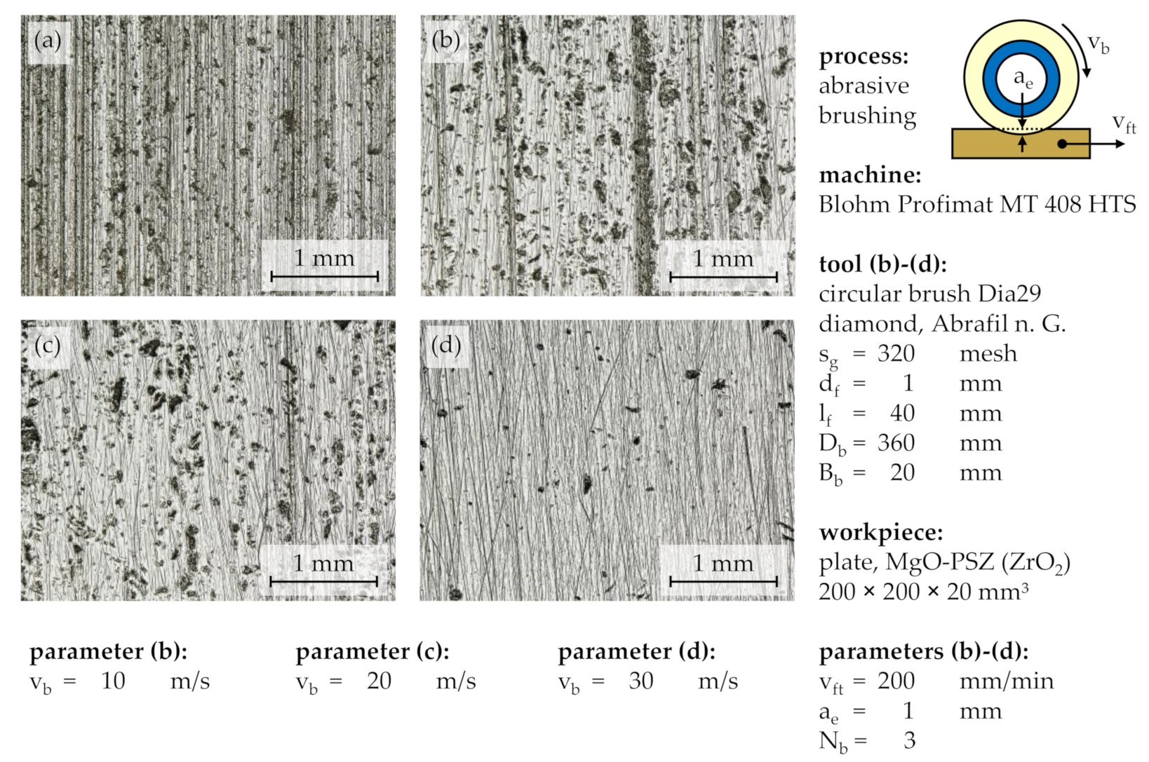
b influenced the processing result, the productivity, and the tool wear. The processing parameter mostly responsible for the number of contacts between the workpiece and the cutting edges of the abrasive grains was the brushing velocity v
b, measured at the filament tip, being the outermost point of the circular brush tool. Its variation showed a significant impact on the removal of the unidirectional grinding grooves and the pockmarks (
Figure 9). Whereas a brushing velocity of v
b = 10 m/s left most of the initial topography unchanged even after a number of brushing cycles of N
b = 3 (
Figure 9b), most unidirectional grinding grooves and some pockmarks were removed with a brushing velocity of v
b = 20 m/s (
Figure 9c), while all grinding grooves and most pockmarks were replaced by multidirectional brushing grooves with a brushing velocity of v
b = 30 m/s (
Figure 9d).
The light microscopy images indicate that the pockmarks were reduced in size as more workpiece material was removed, suggesting that the phenomenon only occurred close to the workpiece surface. This contributes to the assumption that the surface defects were caused by the initial grinding treatment.
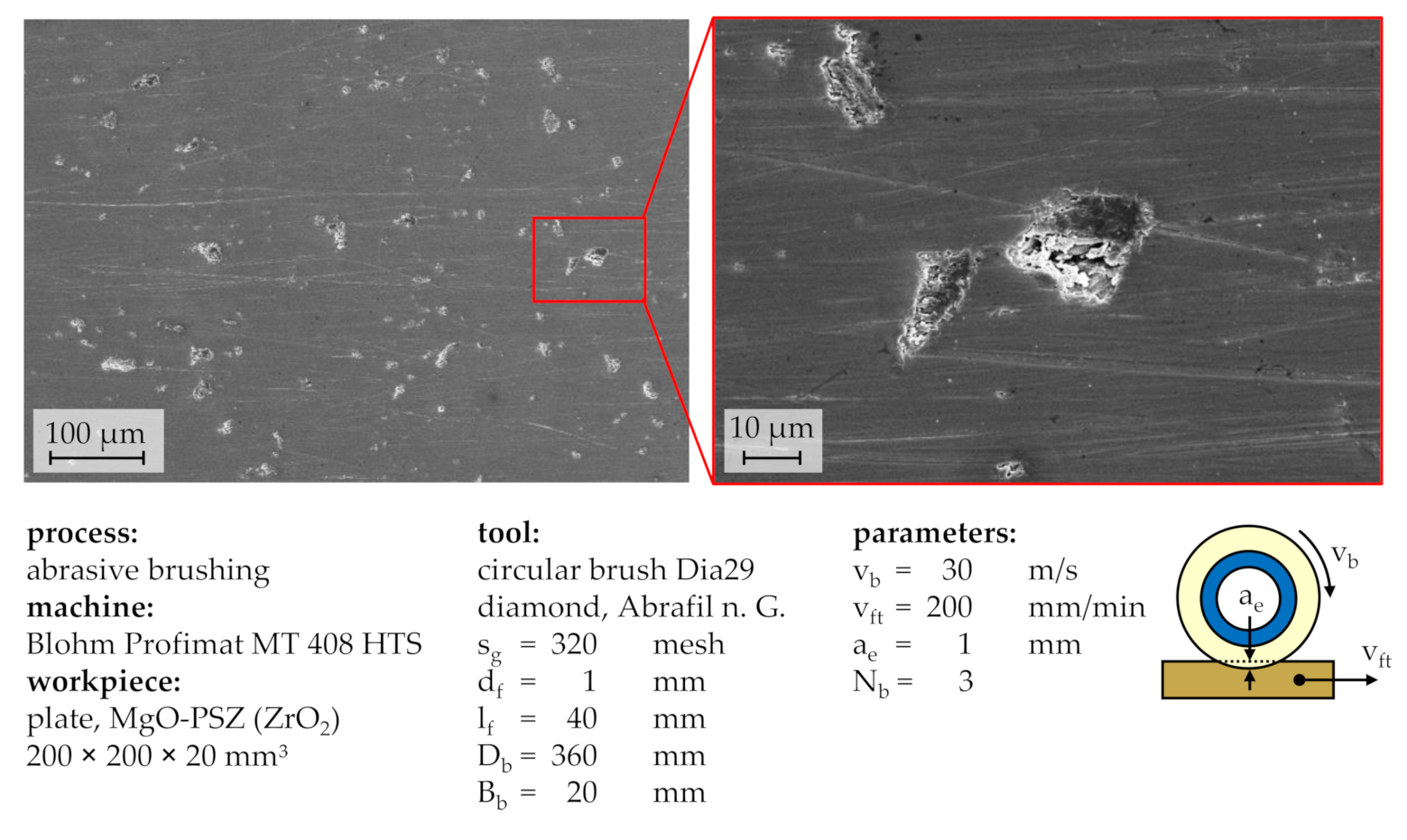
Examining the workpiece surface after a brushing process with a brushing velocity of v
b = 30 m/s on the basis of SEM images (
Figure 10), the multidirectional brushing grooves were less conspicuous than in the corresponding light microscopy images, while the complex shape of the pockmarks as well as their relatively large depths were most salient. Additionally, the edges around the pockmarks appeared rounded, although their rough inward texture depicted the brittleness of the workpiece material.
Comparing the workpiece topographies before and after a high velocity brushing process (
Figure 11), the workpiece form and waviness remained nearly the same, although all previously produced roughness features were removed, indicating the fabrication of an entirely new surface as well as a material removal depth h
r of >9.9 µm, the total height of the initial roughness profile Rt (
Figure 2). The corresponding total height of the roughness profile after N
b = 3 brushing cycles was Rt = 1.9 µm, which amounted to a percental roughness reduction of ∆Rt = 80.7%, approximately the same as the percental peak height reduction of ∆Rpk = 84.2% and the percental valley depth reduction of ∆Rvk = 82.3%. This means that roughness peaks and valleys were equally reduced.
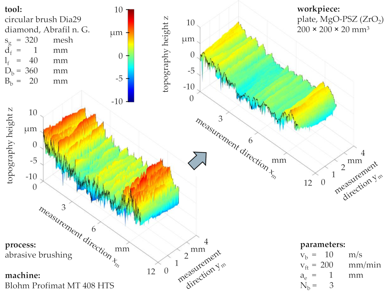
In comparison, the workpiece topography after a brushing process with a brushing velocity of v
b = 10 m/s shows that only the roughness peaks were partially removed while the roughness valleys and the workpiece form remained mostly intact (
Figure 12). With an initial total height of the roughness profile of Rt = 7.8 µm, the resulting total height after N
b = 3 brushing cycles was Rt = 5.5 µm, amounting to a percental roughness reduction of only ∆Rt = 29.7%. The considerable difference between the percental peak height reduction of ∆Rpk = 55.3% and the percental valley depth reduction of ∆Rvk = 32.3% supported the visual observation that roughness peaks were removed more efficiently than roughness valleys. This can be attributed to the fewer and less impactful contacts between abrasive filaments and workpiece compared to processes with high brushing velocities v
b (
Figure 7 and
Figure 11).
In addition, the technological investigations conducted for this work confirmed an independence of the processing result from the feed velocity vft, meaning that multiple brushing cycles Nb at high feed velocities vft amounted to similar results to few brushing cycles Nb at low feed velocities vft, as long as the overall contact duration between tool and workpiece remained the same. Nonetheless, the low heat conductivity of ZrO2 might make brushing at high feed velocities vft more feasible and reduce tool wear due to a better distributed heat flow and more cooling time between brushing cycles, which prevents the plastic matrix of the abrasive filaments from melting and leaving residue on the workpiece, avoiding additional cleaning processes.
Further technological investigations showed no apparent qualitative differences between the penetration depths of a
e = 1 mm, a
e = 2 mm, and a
e = 3 mm in regard to the processing result. However, contemporary research on steel workpieces (16MnCr5) indicates that large penetration depths a
e slightly increase the material removal rate, the reduction of the surface roughness, and the tool wear due to increased contact forces [
7,
9].
The variation of the number of brushing cycles N
b supports the established theory that the surface roughness is reduced successively and regressively, until a lower roughness limit is reached—its value depending mainly on the tool specification—after which consecutive brushing cycles N
b always yield new topographies as opposed to merely reducing certain roughness features such as roughness peaks [
9].
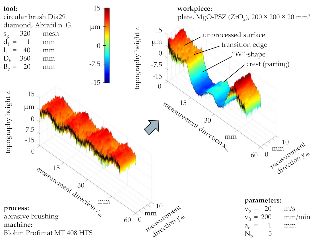
3.4. Processing Result Deviations
Since most aggressive brushing processes, specifically those with a large grain size s
g and a high brushing velocity v
b, do not only alter the surface roughness, but may also lead to a potentially unwanted change of the workpiece form, a more detailed analysis of the proceeding shape deviation is required. Therefore, the measurement length of the workpiece topography was increased to s
m = 50 mm in order to capture the entire width of the brushed profile (
Figure 13), as it was not homogenous due to the diverse interactions between abrasive filaments, depending highly on their positions on the brush body. The technological investigations showed that besides large grain sizes s
g and high brushing velocities v
b, a large number of brushing cycles N
b can also lead to a form deviation after the initial roughness features were completely removed. This resulted in a characteristic “W”-shape, the depth of which was successively increased with each additional brushing cycle. Likewise, noteworthy is that the width of the “W”-shape amounted to ∆x
m = 27.8 mm, more than the nominal tool width of B
b = 20 mm, as the abrasive filaments were parted in the middle and then deflected towards both sides in the axial direction (measurement direction x
m), dodging the high pressure caused by filament interactions and taking the path of least resistance, meaning the axial side obstructed by fewer neighbor filaments. Although a sharp transition from the brushed profile to the unprocessed workpiece surface can be recognized, a small number of protruding abrasive filaments appeared to have been in contact with the unprocessed surface, as the roughness beyond the transition edge was slightly reduced.
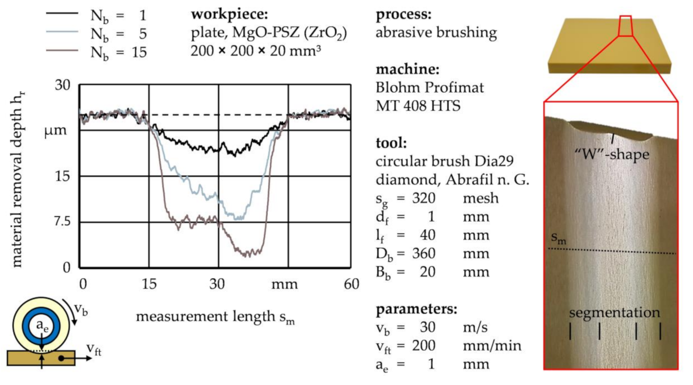
In addition to the workpiece topography, laser distance measurements were made between brushing cycles in order to monitor the workpiece form deviation over time, characterized by the material removal depth h
r across the measurement width s
m (
Figure 14). The hypothesis that the crest of the “W”-shape was formed by the parting of the abrasive filaments as opposed to being predetermined by the initial workpiece waviness, as seen in
Figure 13, was supported by the fact that it was first observed after several brushing cycles, whereas the material removal depth h
r after N
b = 1 brushing cycles resembled a crestless “U”-shape instead. Moreover, the “W”-shapes of most brushing processes showed an asymmetry towards one axial side with less material being removed on the opposite side, presumably resulting from a minor unevenness or inclination of the brushing tool profile and/or the workpiece. As the formation of a “W”-shape was also observed on the brushing tool profile, mutually reinforcing form deviation mechanisms between tool and workpiece were most likely to occur. The technological investigations furthermore suggested that the workpiece material removed per brushing cycle followed a degressive trend, implying that rough surfaces were processed more efficiently than smooth surfaces and large numbers of brushing cycles N
b led to unproductive machining.
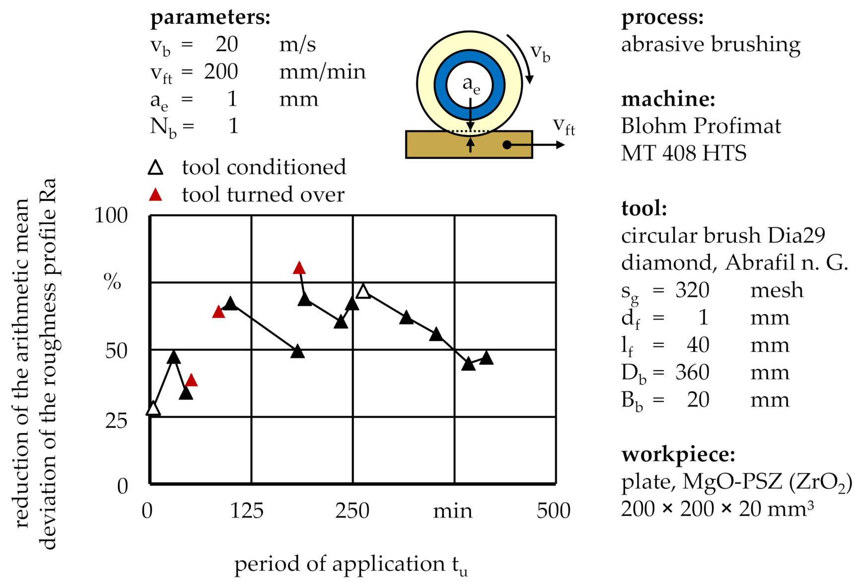
Apart from the aforementioned profile deviation, brushing tools are prone to lose sharpness over time due to an adjustment of the initially cylindrical abrasive filament tips to the workpiece surface, gradually transforming a sharp point contact into a flat, elliptical contact geometry [
11]. Although the interrelations between wear and machining characteristics were not yet scientifically understood, first conclusions can be indirectly drawn from the processing result. One such correlation was the percental reduction of the workpiece roughness, specified by the arithmetic mean deviation of the roughness profile Ra, measured over the entire period of application t
u of the brushing tool (
Figure 15).
After a brief initialization period, the roughness reduction continuously decreased. For the purpose of productivity, the brushing tool either needed to be expensively reconditioned or at moderate cost turned over to utilize the sharp sides of the abrasive filament tips as opposed to the flattened sides. During the technological investigations, these methods resulted in percental roughness reductions between ∆Ra = 28.3% and ∆Ra = 80.6% after single brushing cycles with standard process parameters, using one brushing tool with a grain size of sg = 320 mesh. However, depending on the application, a sudden increase of the material removal rate may be undesirable, as it might cause further form deviation of the workpiece instead of merely roughness reduction. In this case, frequently turning over the brushing tool or changing the rotational direction is advised in order to maintain a consistent level of productivity, represented by the material removal rate.
4. Summary and Discussion
Brushing with bonded abrasives is a finishing process which can be used to enhance the quality of technical surfaces, primarily by decreasing the surface roughness and removing near-surface defects. This could considerably improve the machining results of ceramic materials with defects such as grooves or pockmarks caused by grinding processes, although the finishing of sintered ceramics without preceding grinding treatments is also conceivable in order to decrease the substantial machining costs [
4].
Within the scope of this work, the improvement of the surface quality was demonstrated on the basis of MgO-PSZ (ZrO2) finished with circular brushing tools, the abrasive filaments of which contained PCD. The findings showed that abrasive brushing can furthermore be utilized to create specialized surfaces by only removing roughness peaks while leaving roughness valleys intact. Abrasive filaments with small grain sizes sg proved appropriate for this task, as large grain sizes sg rapidly led to form deviations larger than the total height of the roughness profile Rt and the resulting coarse brushing grooves negatively affected the minimum achievable roughness. Since small grain sizes sg usually require multiple brushing cycles due to the low material removal rate, performing one brushing cycle with coarse grains and one with fine grains might increase productivity, which remains to be confirmed by further experiments. In addition, pending are the influences of filament diameter df and filament length lf on the processing result while brushing ceramics. First experiments suggested that abrasive filaments shorter than lf = 40 mm are prone to take permanent thermal damage due to the low heat conductivity of ZrO2, which in industrial applications could be compensated by adding cooling lubricants.
Additionally, the brushing velocity vb was confirmed to have a significant impact on the machining characteristics, as a high brushing velocity of vb = 30 m/s proved advantageous for the reduction of near-surface defects and yielded topographies with equally reduced roughness peaks and valleys, indicated by a percental peak height reduction of ∆Rpk = 84.2% and a percental valley depth reduction of ∆Rvk = 82.3%. Nevertheless, the complete removal of pre-existing roughness features might be undesirable and also cause excessive tool wear due to increased heat input. In comparison, a low brushing velocity of vb = 10 m/s yielded a percental peak height reduction of ∆Rpk = 55.3% and a percental valley depth reduction of ∆Rvk = 32.3%, and their difference indicated that roughness peaks were removed more efficiently than roughness valleys.
Generally, workpiece form deviations and tool wear developed more rapidly than during comparable technological investigations priorly carried out on steel 16MnCr5 workpieces [
9]. Even with fine grains and medium brushing velocities v
b, after a small number of brushing cycles N
b, the forming of a “W”-shaped workpiece profile was observed, caused by the quasi-symmetrical deflection of the abrasive filaments attached to the lateral area of the cylindrical brush body. However, this might be of no consequence, if pot-shaped brushing tools were used instead, which comprised abrasive filaments attached to the base area of the cylindrical brush body, therefore yielding different kinematic relations as well as circular brushing groove patterns on the workpiece surface.
Tool wear was measured based on the consistency of processing results, specifically the arithmetic mean deviation of the roughness profile Ra, and could be compensated by frequent turning of the brushing tool or alternating of the rotational direction. A wear study based on the change in form of single abrasive filament tips remains yet to be conducted.


