MARMA: A Mobile Augmented Reality Maintenance Assistant for Fast-Track Repair Procedures in the Context of Industry 4.0
Abstract
1. Introduction
- A supportive system is introduced, which can be used by unskilled operators to perform maintenance operations in night shifts.
- The platform is executed in personal mobile phones or tablets, eliminating the investment costs of using expensive AR kits.
- The system is able to locate the asset inside the complex manufacturing shop floor without human intervention.
- The proposed solution can replace the paper-based instructions with digital ones, exploiting AR functions to limit the retrieval times.
- Our system is anticipated to reduce the knowledge gap between the manufacturers and maintenance operators.
2. Related Work
3. Tools
3.1. Object Detector
3.2. 3D Modeling Design
3.3. Augmented Reality Software Development Kit (SDK)
3.4. 3D Engine
4. Methodology
4.1. 3D Model Design Philoshopy
4.2. 3D Target Model
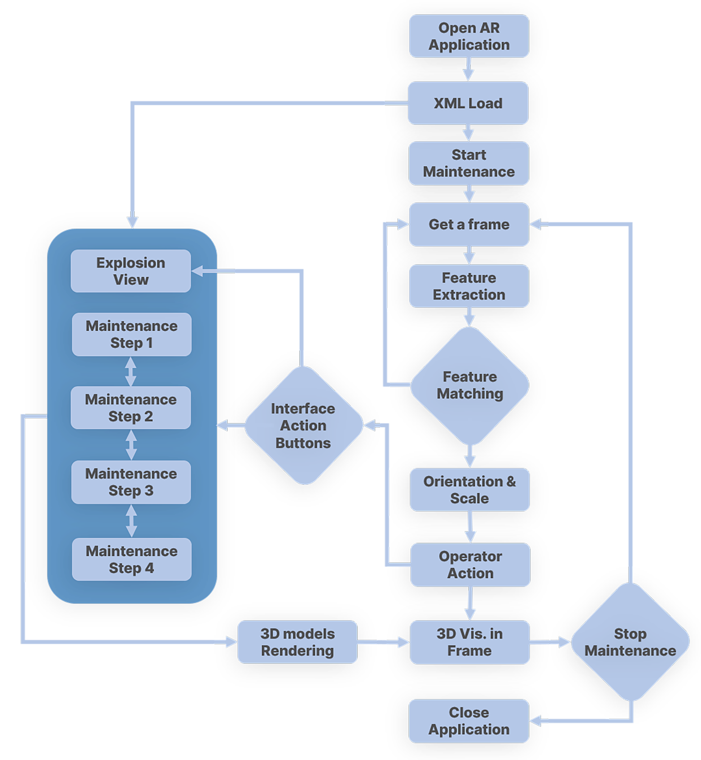
4.3. Feature Matching and Tracking
4.4. Orientation and Scale
4.5. 3D Visualization
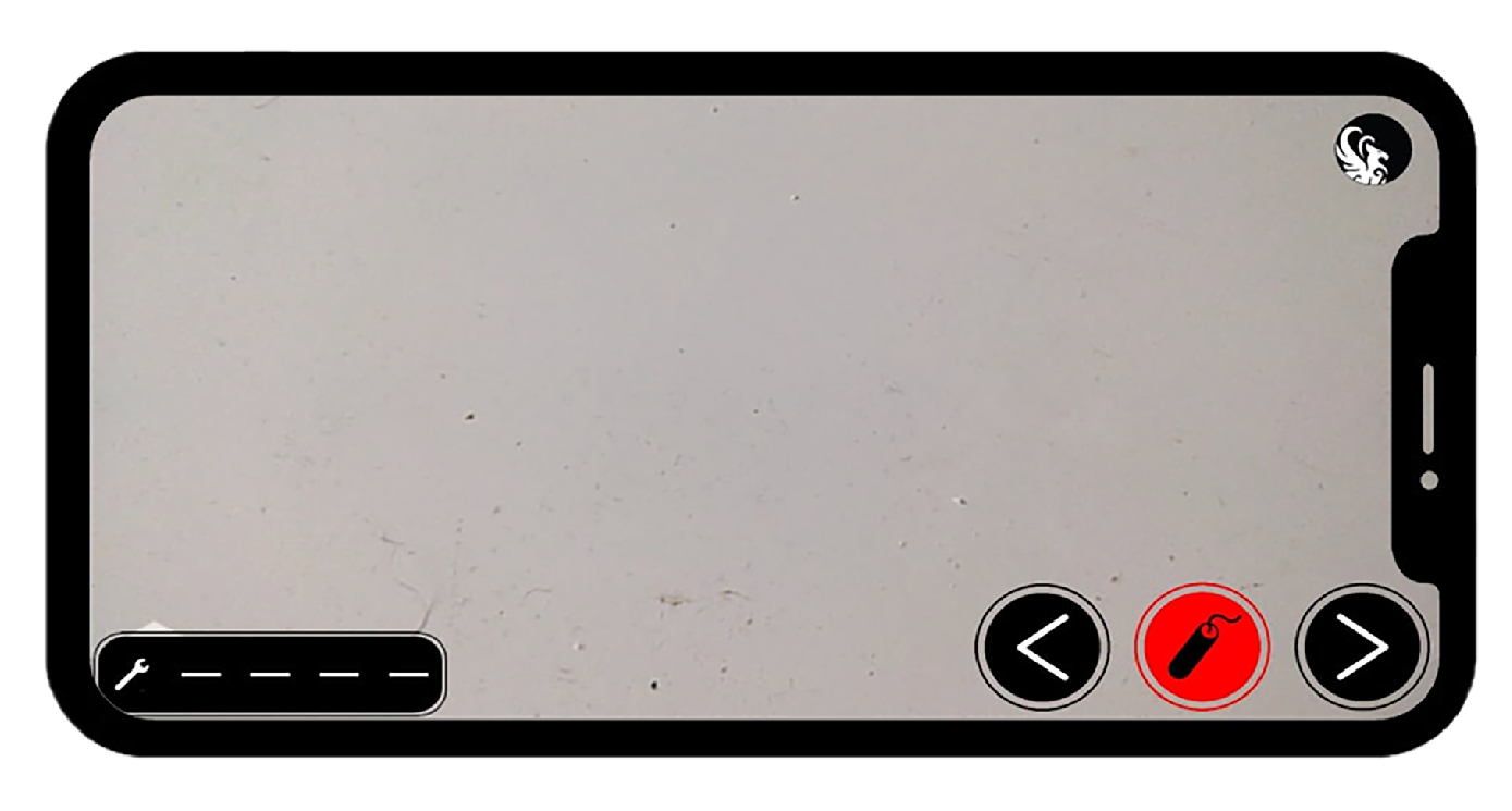
4.6. User Interface
4.7. Unity
5. Experimental Process
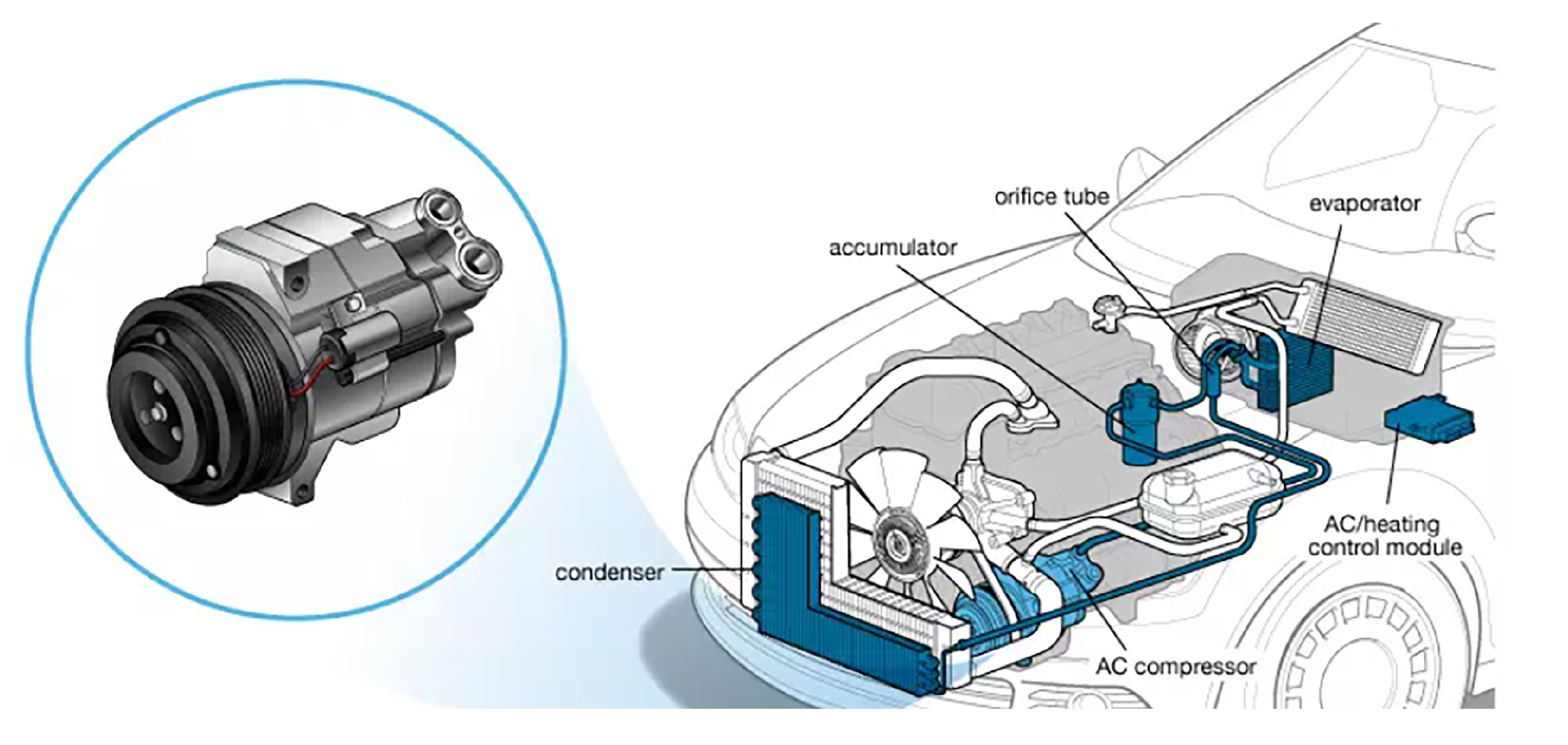
5.1. Maintenance Scenario Setup
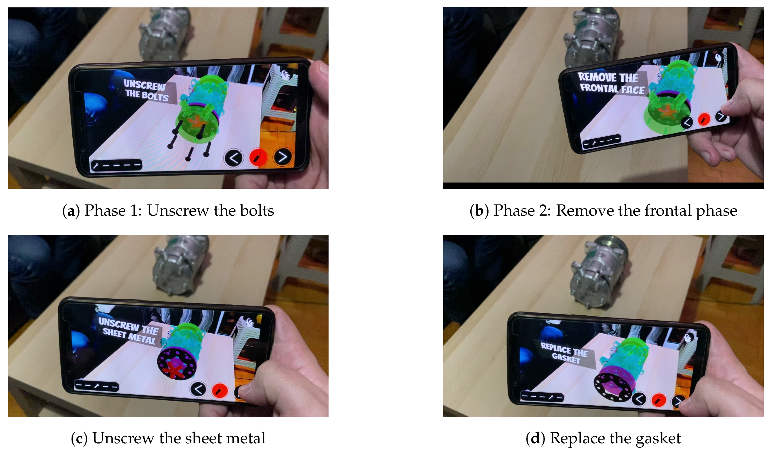
- Phase 1: Remove the bolts
- Phase 2: Remove the frontal phase
- Phase 3: Unscrew the sheet metal
- Phase 4: Replace the gasket
- Phase 5: Clean the metal flange
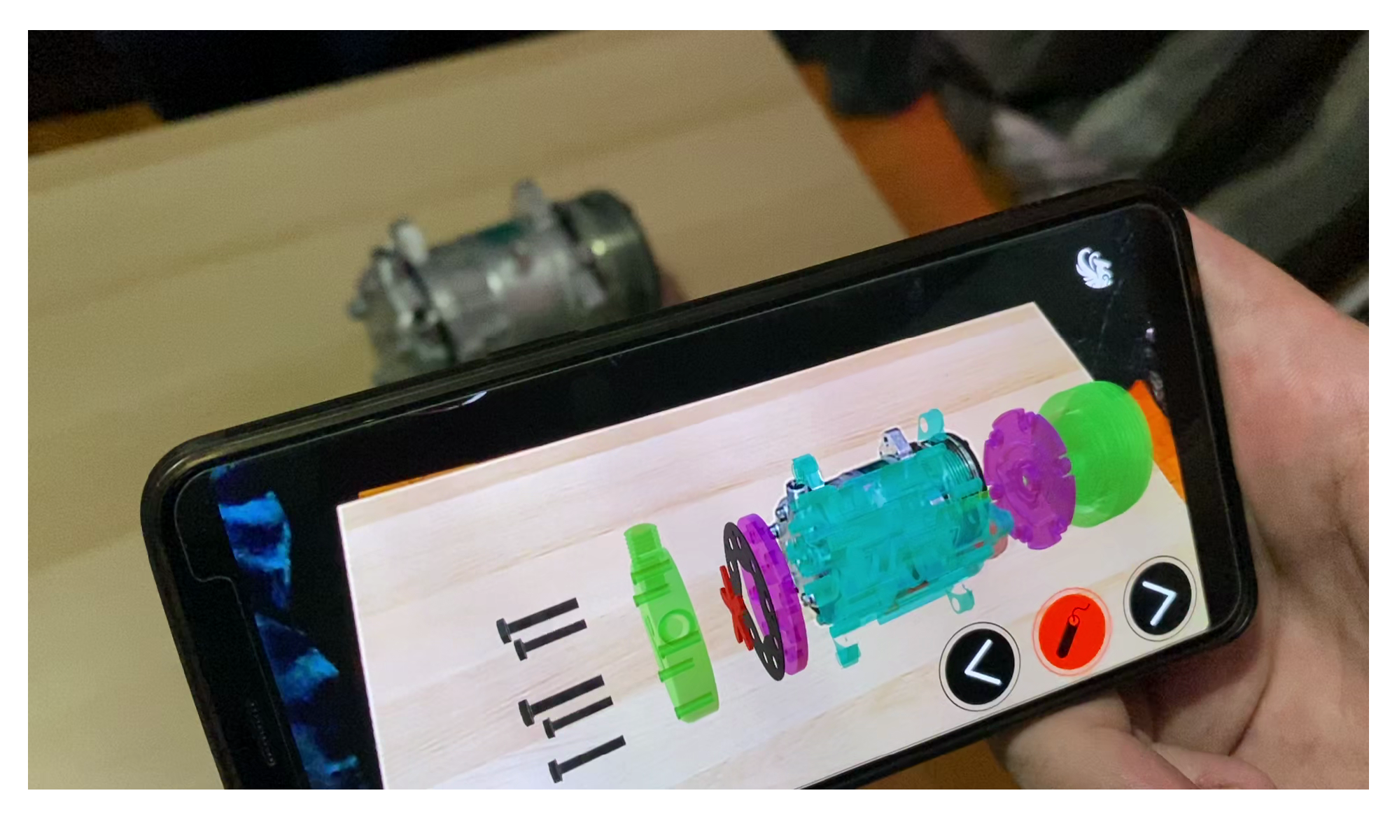
5.2. Demonstration
6. Conclusions and Future Work
Author Contributions
Funding
Conflicts of Interest
References
- Konstantinidis, F.K.; Gasteratos, A.; Mouroutsos, S.G. Vision-Based Product Tracking Method for Cyber-Physical Production Systems in Industry 4.0. In Proceedings of the 2018 IEEE International Conference on Imaging Systems and Techniques (IST), Krakow, Poland, 16–18 October 2018; pp. 1–6. [Google Scholar]
- Benakis, M.; Du, C.; Patran, A.; French, R. Welding Process Monitoring Applications and Industry 4.0. In Proceedings of the 2019 IEEE 15th International Conference on Automation Science and Engineering (CASE), Vancouver, BC, Canada, 22–26 August 2019; pp. 1755–1760. [Google Scholar]
- Ruppert, T.; Jaskó, S.; Holczinger, T.; Abonyi, J. Enabling technologies for operator 4.0: A survey. Appl. Sci. 2018, 8, 1650. [Google Scholar] [CrossRef]
- Wlazlak, P.; Säfsten, K.; Hilletofth, P. Original equipment manufacturer (OEM)-supplier integration to prepare for production ramp-up. J. Manuf. Technol. Manag. 2019, 30, 506–530. [Google Scholar] [CrossRef]
- Gallala, A.; Hichri, B.; Plapper, P. Survey: The Evolution of the Usage of Augmented Reality in Industry 4.0. In Proceedings of the IOP Conference Series: Materials Science and Engineering, Bangkok, Thailand, 17–19 May 2019; pp. 12–17. [Google Scholar]
- Mourtzis, D.; Vlachou, E.; Milas, N.; Xanthopoulos, N. A cloud-based approach for maintenance of machine tools and equipment based on shop-floor monitoring. Procedia CIRP 2016, 41, 655–660. [Google Scholar] [CrossRef]
- Palmarini, R.; Erkoyuncu, J.A.; Roy, R.; Torabmostaedi, H. A systematic review of augmented reality applications in maintenance. Robot. Comput. Integr. Manuf. 2018, 49, 215–228. [Google Scholar] [CrossRef]
- Spranger, J.; Buzatoiu, R.; Polydoros, A.; Nalpantidis, L.; Boukas, E. Human-Machine Interface for Remote Training of Robot Tasks. arXiv 2018, arXiv:1809.09558. [Google Scholar]
- Muzzamil, F.; Syafrida, R.; Permana, H. The effects of smartphones on social skills in Industry 4.0. In Teacher Education and Professional Development In Industry 4.0: Proceedings of the 4th International Conference on Teacher Education and Professional Development (InCoTEPD 2019), Yogyakarta, Indonesia, 13–14 November 2019; CRC Press: Boca Raton, FL, USA, 2020; p. 72. [Google Scholar]
- Simonetti Ibañez, A.; Paredes Figueras, J. Vuforia v1. 5 SDK: Analysis and Evaluation of Capabilities. Master’s Thesis, Universitat Politècnica de Catalunya, Barcelona, Spain, 2013. [Google Scholar]
- SEV. Industry 4.0: A Growth Opportunity Greece should not Miss by Hellenic Federation of Enterprises. 2019. Available online: https://en.sev.org.gr/events/industry-4-0-a-growth-opportunity-greece-should-not-miss-18-19-december-2019/ (accessed on 20 December 2020).
- Pérez, L.; Rodríguez, Í.; Rodríguez, N.; Usamentiaga, R.; García, D.F. Robot guidance using machine vision techniques in industrial environments: A comparative review. Sensors 2016, 16, 335. [Google Scholar] [CrossRef] [PubMed]
- Tsintotas, K.A.; Giannis, P.; Bampis, L.; Gasteratos, A. Appearance-Based Loop Closure Detection with Scale-Restrictive Visual Features. In ICVS 2019: Computer Vision Systems; Springer: Cham, Switzerland, 2019; pp. 75–87. [Google Scholar]
- Bottani, E.; Vignali, G. Augmented reality technology in the manufacturing industry: A review of the last decade. IISE Trans. 2019, 51, 284–310. [Google Scholar] [CrossRef]
- Kansizoglou, I.; Bampis, L.; Gasteratos, A. An Active Learning Paradigm for Online Audio-Visual Emotion Recognition. IEEE Trans. Affect. Comput. 2019. [Google Scholar] [CrossRef]
- Santavas, N.; Kansizoglou, I.; Bampis, L.; Karakasis, E.; Gasteratos, A. Attention! A Lightweight 2D Hand Pose Estimation Approach. IEEE Sens. J. 2020. [Google Scholar] [CrossRef]
- Balaska, V.; Bampis, L.; Boudourides, M.; Gasteratos, A. Unsupervised semantic clustering and localization for mobile robotics tasks. Robot. Auton. Syst. 2020, 131, 103567. [Google Scholar] [CrossRef]
- Velosa, J.D.; Cobo, L.; Castillo, F.; Castillo, C. Methodological proposal for use of Virtual Reality VR and Augmented Reality AR in the formation of professional skills in industrial maintenance and industrial safety. In Online Engineering & Internet of Things; Springer: Cham, Switzerland, 2018; pp. 987–1000. [Google Scholar]
- De Amicis, R.; Ceruti, A.; Francia, D.; Frizziero, L.; Simões, B. Augmented Reality for virtual user manual. Int. J. Interact. Des. Manuf. (IJIDeM) 2018, 12, 689–697. [Google Scholar] [CrossRef]
- Moser, T.; Hohlagschwandtner, M.; Kormann-Hainzl, G.; Pölzlbauer, S.; Wolfartsberger, J. Mixed Reality Applications in Industry: Challenges and Research Areas. In SWQD 2019: Software Quality: The Complexity and Challenges of Software Engineering and Software Quality in the Cloud; Springer: Cham, Switzerland, 2019; pp. 95–105. [Google Scholar]
- Aleksy, M.; Troost, M.; Scheinhardt, F.; Zank, G.T. Utilizing hololens to support industrial service processes. In Proceedings of the 2018 IEEE 32nd International Conference on Advanced Information Networking and Applications (AINA), Krakow, Poland, 16–18 May 2018; pp. 143–148. [Google Scholar]
- Pierdicca, R.; Prist, M.; Monteriù, A.; Frontoni, E.; Ciarapica, F.; Bevilacqua, M.; Mazzuto, G. Augmented Reality Smart Glasses in the Workplace: Safety and Security in the Fourth Industrial Revolution Era. In AVR 2020: Augmented Reality, Virtual Reality, and Computer Graphics; Springer: Cham, Switzerland, 2020; pp. 231–247. [Google Scholar]
- Kim, S.; Nussbaum, M.A.; Gabbard, J.L. Influences of augmented reality head-worn display type and user interface design on performance and usability in simulated warehouse order picking. Appl. Ergon. 2019, 74, 186–193. [Google Scholar] [CrossRef] [PubMed]
- Werrlich, S.; Nitsche, K.; Notni, G. Demand analysis for an augmented reality based assembly training. In Proceedings of the 10th International Conference on PErvasive Technologies Related to Assistive Environments, Island of Rhodes, Greece, 21–23 June 2017; pp. 416–422. [Google Scholar]
- Eschen, H.; Kötter, T.; Rodeck, R.; Harnisch, M.; Schüppstuhl, T. Augmented and virtual reality for inspection and maintenance processes in the aviation industry. Procedia Manuf. 2018, 19, 156–163. [Google Scholar] [CrossRef]
- Li, S.; Zheng, P.; Zheng, L. An AR-Assisted Deep Learning Based Approach for Automatic Inspection of Aviation Connectors. IEEE Trans. Ind. Inform. 2020, 17, 1721–1731. [Google Scholar] [CrossRef]
- Ceruti, A.; Marzocca, P.; Liverani, A.; Bil, C. Maintenance in aeronautics in an Industry 4.0 context: The role of Augmented Reality and Additive Manufacturing. J. Comput. Des. Eng. 2019, 6, 516–526. [Google Scholar] [CrossRef]
- Freddi, M.; Frizziero, L. Design for Disassembly and Augmented Reality Applied to a Tailstock. Actuators 2020, 9, 102. [Google Scholar] [CrossRef]
- Mourtzis, D.; Siatras, V.; Angelopoulos, J. Real-Time Remote Maintenance Support Based on Augmented Reality (AR). Appl. Sci. 2020, 10, 1855. [Google Scholar] [CrossRef]
- He, F.; Ong, S.K.; Nee, A.Y. A Mobile Solution for Augmenting a Manufacturing Environment with User-Generated Annotations. Information 2019, 10, 60. [Google Scholar] [CrossRef]
- Arntz, A.; Keßler, D.; Borgert, N.; Zengeler, N.; Jansen, M.; Handmann, U.; Eimler, S.C. Navigating a Heavy Industry Environment Using Augmented Reality-A Comparison of Two Indoor Navigation Designs. In HCII 2020: Virtual, Augmented and Mixed Reality. Industrial and Everyday Life Applications; Springer: Cham, Switzerland, 2020; pp. 3–18. [Google Scholar]
- Fang, W.; Zheng, S.; Liu, Z. A Scalable and Long-Term Wearable Augmented Reality System for Order Picking. In Proceedings of the 2019 IEEE International Symposium on Mixed and Augmented Reality Adjunct (ISMAR-Adjunct), Beijing, China, 10–18 October 2019; pp. 4–7. [Google Scholar]
- Limeira, M.; Piardi, L.; Kalempa, V.C.; Schneider, A.; Leitão, P. Augmented Reality System for Multi-robot Experimentation in Warehouse Logistics. In Proceedings of the Iberian Robotics Conference, Porto, Portugal, 20–22 November 2019; pp. 319–330. [Google Scholar]
- Sarupuri, B.; Lee, G.A.; Billinghurst, M. An augmented reality guide for assisting forklift operation. In Proceedings of the 2016 IEEE International Symposium on Mixed and Augmented Reality (ISMAR-Adjunct), Merida, Mexico, 19–23 September 2016; pp. 59–60. [Google Scholar]
- Kapinus, M.; Beran, V.; Materna, Z.; Bambušek, D. Spatially Situated End-User Robot Programming in Augmented Reality. In Proceedings of the 2019 28th IEEE International Conference on Robot and Human Interactive Communication (RO-MAN), New Delhi, India, 14–18 October 2019; pp. 1–8. [Google Scholar]
- Zacharaki, A.; Kostavelis, I.; Gasteratos, A.; Dokas, I. Safety bounds in human robot interaction: A survey. Saf. Sci. 2020, 127, 104667. [Google Scholar] [CrossRef]
- Sanna, A.; Manuri, F.; Lamberti, F.; Paravati, G.; Pezzolla, P. Using handheld devices to sup port augmented reality-based maintenance and assembly tasks. In Proceedings of the 2015 IEEE International Conference on Consumer Electronics (ICCE), Las Vegas, NV, USA, 9–12 January 2015; pp. 178–179. [Google Scholar]
- Vignali, G.; Bertolini, M.; Bottani, E.; Di Donato, L.; Ferraro, A.; Longo, F. Design and testing of an augmented reality solution to enhance operator safety in the food industry. Int. J. Food Eng. 2017, 14. [Google Scholar] [CrossRef]
- Kyriakoulis, N.; Gasteratos, A. Color-based monocular visuoinertial 3-D pose estimation of a volant robot. IEEE Trans. Instrum. Meas. 2010, 59, 2706–2715. [Google Scholar] [CrossRef]
- Metta, G.; Gasteratos, A.; Sandini, G. Learning to track colored objects with log-polar vision. Mechatronics 2004, 14, 989–1006. [Google Scholar] [CrossRef][Green Version]
- Redmon, J.; Divvala, S.; Girshick, R.; Farhadi, A. You only look once: Unified, real-time object detection. In Proceedings of the IEEE Conference on Computer Vision and Pattern Recognition, Las Vegas, NV, USA, 27–30 June 2016; pp. 779–788. [Google Scholar]
- Womg, A.; Shafiee, M.J.; Li, F.; Chwyl, B. Tiny SSD: A tiny single-shot detection deep convolutional neural network for real-time embedded object detection. In Proceedings of the 2018 15th Conference on Computer and Robot Vision (CRV), Toronto, ON, Canada, 9–11 May 2018; pp. 95–101. [Google Scholar]
- Bethune, J.D. Engineering Design Graphics with Autodesk Inventor 2020; Macromedia Press: San Francisco, CA, USA, 2019. [Google Scholar]
- Linowes, J.; Babilinski, K. Augmented Reality for Developers: Build Practical Augmented Reality Applications with Unity, ARCore, ARKit, and Vuforia; Packt Publishing Ltd.: Mumbai, India, 2017. [Google Scholar]
- Bay, H.; Tuytelaars, T.; Van Gool, L. Surf: Speeded up robust features. In Proceedings of the European Conference on Computer Vision, Graz, Austria, 7–13 May 2006; pp. 404–417. [Google Scholar]
- Wagner, D.; Reitmayr, G.; Mulloni, A.; Drummond, T.; Schmalstieg, D. Pose tracking from natural features on mobile phones. In Proceedings of the 2008 7th IEEE/ACM International Symposium on Mixed and Augmented Reality, Cambridge, UK, 15–18 September 2008; pp. 125–134. [Google Scholar]
- Tsintotas, K.A.; Bampis, L.; Gasteratos, A. DOSeqSLAM: Dynamic on-line sequence based loop closure detection algorithm for SLAM. In Proceedings of the 2018 IEEE International Conference on Imaging Systems and Techniques (IST), Krakow, Poland, 16–18 October 2018; pp. 1–6. [Google Scholar]
- Wang, S.; Mao, Z.; Zeng, C.; Gong, H.; Li, S.; Chen, B. A new method of virtual reality based on Unity3D. In Proceedings of the 2010 18th international conference on Geoinformatics, Beijing, China, 18–20 June 2010; pp. 1–5. [Google Scholar]
- Park, Y.H. Human Cognitive Task Distribution Model for Maintenance Support System of a Nuclear Power Plant. Master’s Thesis, Korea Advanced Institute of Science and Technology, Daejeon, Korea, 2007. [Google Scholar]
- D’Anniballe, A.; Silva, J.; Marzocca, P.; Ceruti, A. The role of augmented reality in air accident investigation and practitioner training. Reliab. Eng. Syst. Saf. 2020, 204, 107149. [Google Scholar] [CrossRef]
- Michalis, P.; Konstantinidis, F.; Valyrakis, M. The road towards Civil Infrastructure 4.0 for proactive asset management of critical infrastructure systems. In Proceedings of the 2nd International Conference on Natural Hazards & Infrastructure (ICONHIC), Chania, Greece, 23–26 June 2019; pp. 23–26. [Google Scholar]
- Chen, P.; Liu, X.; Cheng, W.; Huang, R. A review of using Augmented Reality in Education from 2011 to 2016. In Innovations in Smart Learning; Springer: Singapore, 2017; pp. 13–18. [Google Scholar]
- Tirkel, I.; Rabinowitz, G. Modeling cost benefit analysis of inspection in a production line. Int. J. Prod. Econ. 2014, 147, 38–45. [Google Scholar] [CrossRef]


Publisher’s Note: MDPI stays neutral with regard to jurisdictional claims in published maps and institutional affiliations. |
© 2020 by the authors. Licensee MDPI, Basel, Switzerland. This article is an open access article distributed under the terms and conditions of the Creative Commons Attribution (CC BY) license (http://creativecommons.org/licenses/by/4.0/).
Share and Cite
Konstantinidis, F.K.; Kansizoglou, I.; Santavas, N.; Mouroutsos, S.G.; Gasteratos, A. MARMA: A Mobile Augmented Reality Maintenance Assistant for Fast-Track Repair Procedures in the Context of Industry 4.0. Machines 2020, 8, 88. https://doi.org/10.3390/machines8040088
Konstantinidis FK, Kansizoglou I, Santavas N, Mouroutsos SG, Gasteratos A. MARMA: A Mobile Augmented Reality Maintenance Assistant for Fast-Track Repair Procedures in the Context of Industry 4.0. Machines. 2020; 8(4):88. https://doi.org/10.3390/machines8040088
Chicago/Turabian StyleKonstantinidis, Fotios K., Ioannis Kansizoglou, Nicholas Santavas, Spyridon G. Mouroutsos, and Antonios Gasteratos. 2020. "MARMA: A Mobile Augmented Reality Maintenance Assistant for Fast-Track Repair Procedures in the Context of Industry 4.0" Machines 8, no. 4: 88. https://doi.org/10.3390/machines8040088
APA StyleKonstantinidis, F. K., Kansizoglou, I., Santavas, N., Mouroutsos, S. G., & Gasteratos, A. (2020). MARMA: A Mobile Augmented Reality Maintenance Assistant for Fast-Track Repair Procedures in the Context of Industry 4.0. Machines, 8(4), 88. https://doi.org/10.3390/machines8040088


