1. Introduction
During research in recent decades, industry has investigated the applications of mobile robots in medicine, automotive, military, search and rescue, agricultural, services, underwater research, personal and other many applications in real life [
1,
2,
3,
4,
5,
6,
7,
8]. In any of these pivotal applications, the robot needs to interact with the environment. Also, it is required to do their tasks without or with minimum human input and control. As a result, it is desired to complete their missions and reach the desired destination (goal). This problem is well known in the field of robotics as a motion-planning and control problem. Many works on the topic have been investigated; the objective focuses on generating a collision-free path from the current state of the robot to the final destination. Obstacle avoidance is considered one of the basic requirements for the robot to do the task efficiently. In 1985, Oussama Khatib proposed a new method for real-time obstacle avoidance for mobile robots based on the artificial potential field. The potential field considers the robot’s environment as a field of forces. The goal destination attracts the robot (attractive force); in contrast, the obstacles are considered repulsive forces that push the robot away. The resultant force is the sum of attractive and repulsive forces. They extended the method for moving objects by using time-varying artificial filed methods [
9,
10]. In [
11], Zavlangas et al. proposed a local, real-time fuzzy-based approach for navigation and obstacle avoidance for omnidirectional mobile robots. They consider the nearest obstacle strategy in the fuzzy-based path planning algorithm. The algorithm considers the distance, location to the nearest obstacle, and the robot’s current position and direction and destination.
In [
12], Ren et al. presented a fuzzy-based intelligent obstacle-avoidance strategy for the wheeled mobile robot. The robot controller consists of two main fuzzy logic controllers. When there are no obstacles in the robot’s path, the Run-to-Goal controller is responsible for making the robot approach the desired goal. In the presence of any obstacle, while it is heading to the goal, another fuzzy-based obstacle controller will generate commands to the robot to avoid that obstacle. As a more potent tool, in 2019, Nadour et al. presented a hybrid type-2 fuzzy controller and optical flow approach using the Horn–Shunk algorithm. They used the Takagi–Sugeno fuzzy controller to avoid the detected obstacle based on another image processing algorithm. The obstacle and its position are defined in the image processing using the Horn–Shunk algorithm. The results show the effectiveness of the visual-based navigation system [
13].
In [
14], the authors introduced a real-time optimal path planning of humanoid robots. They discussed the problem of the unknown environment with the presence of dangerous space. They defined the danger space where the robot is permitted to go when no free space available to go through. In other words, the robots cannot cross the danger space once at least one free path is available. Mud pits and greasy areas are examples of these dangerous areas. They also used a modified Markov decision method based on the Takagi–Sugeno fuzzy system to achieve the task (reach the destination in the presence of danger area).
Since it has wide applications and use, autonomous mobile robots must work with reliable performance and increased autonomy. The type of wheel, the configuration of the autonomous robot, and the actuators’ availability determine the robot’s capabilities and ability to maneuver in its environment. When the robot moves in an environment with N physical dimensions, and it has geometrical constraints on due to the interaction with the ground, then this type of robots called a non-holonomic, and in this case, the robot has a set of geometrical constraints and cannot move in all physical dimensions. In other words, the robot has fewer degrees of freedom (DOF) than the total available due to the constraints on the robot. Car-like robots, Unicycle, and differential drive robots are examples of non-holonomic robots.
In contrast, the holonomic robots can move in any direction (with N dimensions) of its space [
15,
16]. In these types of robots, the robot can be controlled to move in any direction since it has the same controllable directions as the same as the total DOF. The robot can move and rotate in any directions freely without any geometrical constraints, which make these types of robots at the center of the attention. The omnidirectional wheel mobile robot is an example of a holonomic mobile robot. In this type of ground robots, the robot can move or rotate in any direction based on the actuators’ commands.
In most cases, designers and researchers build a navigation algorithm and assume the robot working with all its functions. In real applications, this is not the case, and the robot may suffer from faults in one or more of its actuators or/and sensors. For the robot to work efficiently and reach its goals in these cases, it must express and show tolerant behavior [
15,
17,
18,
19]. The fault diagnosis method is known as fault detection and identification (FDI), the system’s actual response is compared to the response of the theoretical response for the same input signal, if there is a deviation between these responses, then the fault is detected [
20].
After identifying the fault, the next step is to impart fault-tolerant control that retains the system’s performance and behavior, the closest possible to the ideal situation just before the fault. In literature, there are two main fault-tolerant control techniques used in such cases. The first one is the passive approach, in which the fault is considered a perturbation to the system. The second approach is the active method, where the pre-defined or new online control algorithms are used after identifying the system’s faults. This pre-defined control algorithm depends on the type of failure in the systems; it may occur in one part, or a combination between more than one failure in the actuators or/and the sensors [
15,
16,
21,
22,
23].
In [
24], the authors presented the kinematics and a method for fault-tolerant control of a three-wheel omnidirectional soccer robot, to deal with the sudden failure of one motor during the match. Ref. [
23] proposed a novel gear train omnidirectional mechanism for precise and high robot mobility. In this paper, the fault tolerance problem of the omnidirectional wheels was dealt with the gear train’s mechanical design. The mechanism uses three motors with conventional tire wheels. When one of the three motors are not working correctly, the robot motion is controlled by the other two healthy motors; in this case, the robot’s structure and movement becomes similar to a differential two-wheeled mobile robot subjected to non-holonomic constraints [
23]. Chao Ren et al. presented a reduced-order extended state observer-based sliding mode control for a three omnidirectional robot with friction compensation [
25].
Qi Song et al. proposed a fault-tolerant control based on a three-degree omnidirectional robot’s inverse dynamics. The inverse dynamic control is enhanced by actuator effectiveness factors introduced to the omnidirectional robot’s dynamic equation. Unscented Kalman filter is used to estimate the robot’s state and the actuator effectiveness factors [
26].
The paper [
27] represents an analysis of the four Mecanum-wheeled omnidirectional robot and performance analysis of trajectory tracking in case of one fault and two faults in the wheel’s motors. The robot gives the desired performance in one fault case, and the system remains in its full actuation capabilities. The performance was not the same for the two motors’ faults situation, where some of these fault combinations do not give the desired performance while some do.
Damiano Rotondo et al. proposed trajectory tracking control of a four-wheeled omnidirectional mobile robot based on the reference model approach. The control loop was enhanced by adding a switching quasi-Linear Parameter Varying to obtain fault tolerance. A set of simulations and experiments were performed to check the performance of the proposed method [
28]. The work in [
29] studies the FDI of actuation and sensing of an omnidirectional mobile robot with four Mecanum wheels. The approach is based on residual where the isolation of sensors based on the analyzing residual signatures, which are different for each sensor fault. For actuators faults more residual characteristics are taken into consideration to achieve the isolation.
In [
30] Damiano Rotondo et al. present fault-tolerant control of an omnidirectional robot using a Switched Takagi–Sugeno approach strategy. To achieve the desired performance and keep the stability, they rely on their adaptive controller solution. To prove the effectiveness of the proposed controller, experiential results obtained for a four-wheeled omnidirectional mobile robot. Based on the experimental results that showed potential and performance, the proposed control approach was able to recover the desired trajectory tracking when the first wheel motor was subjected to a loos of effectiveness fault. All the mentioned FTC schemes deal with trajectory control, and no one discusses this problem in the presence of obstacles in the robot’s path. Ref. [
15] presents the design of an FTC for an omnidirectional robot with four Mecanum wheels. In this research, a non-linear predictive controller is proposed to solve multiple combinations of actuation faults problem. Depending on the identified fault, the control vector and the dynamic of the robot are reconstructed.
In this paper, we proposed a fuzzy-based tolerant control strategy for a four-wheel Mecanum omnidirectional mobile robot which appropriately uses the robot’s actuation redundancy, so this will afford adaptive control solutions in the case of failure of one actuator or more of the robot. The proposed navigation and control strategy is based on Takagi–Sugeno Fuzzy Model and is composed of two fuzzy logic controllers. The first one is the Run-to-Goal controller which will control the robot to go to the final goal. In detecting an obstacle in the robot path, the second obstacle-avoidance controller will take the robot away from the obstacle, which depends on the position and the directions of both the obstacle and the final destination relative to the robot’s orientation and position. These two controllers and the fuzzy rules and output to the actuators are adaptive and modified based on their health condition. We consider actuation faults where the wheels can rotate freely due to the friction with the ground but cannot receive the controller’s control signal.
This paper’s main contribution is to design an adaptive fault-based controller with a fast response and suitable for an online application scheme to control the omnidirectional robot with four Mecanum wheels robot motion. Consequently, this controller can control the robot to reach its final destination with the absence and presence of an obstacle in the workspace, which lacks most literary works, despite the existence of actuator faults, without crossing the workspace boundaries.
2. Kinematics and Dynamics of the 4 Mecanum Omnidirectional Wheel Mobile Robot
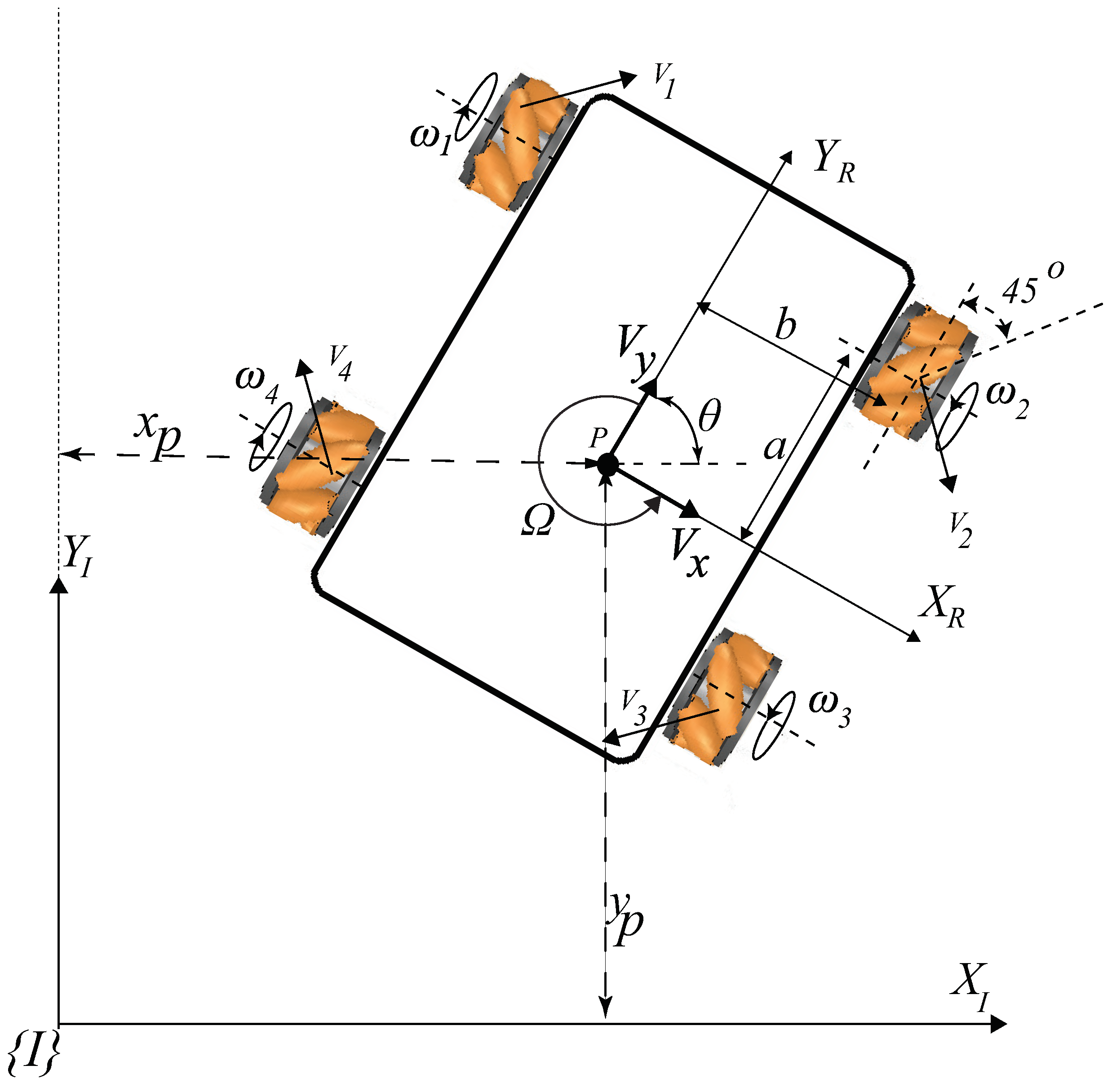
In this paper, we assume the robot as a rigid body on 4-mecanum wheels omnidirectional robot. The model assumes that the robot operates on a horizontal plane, and it considers that there is no slippage on the robot’s wheels. Also, we assume that the robot’s geometric parameters are known as well as the dynamic parameters. As a result, the robot chassis has a three-dimensionality, two for the plane’s position, and the third dimension for the robot’s orientation around the orthogonal axes to the plane of motion. Referring to
Figure 1, the global reference frame is defined by the two axes
and
from the origin
. To determine the robot’s position, we choose the point
on the robot’s center as a reference point. The robot’s body reference frame is defined by the two axes
relative to the robot’s center
. Thus, the robot poses
can be described using the position of the point
relative to the inertial reference frame
I, and the angular rotation of the robot
relative to the
I.
To describe the robot motion with respect to the
I:
where
is an orthogonal 7 the rotational matrix used to map the motion in the local reference frame
to the global reference frame
. Also,
is the body velocity vector of the robot in the local reference frame and given by
. Since the robot has four wheels and each wheel has a radius r, and rotate with a rotational velocity
, then we can relate the body velocity vector
to the wheels rotational velocities vector
, using the following expression:
Assuming that the offset of roller for the omnidirectional wheels used in this research is 45
. Then the Jacobean matrix
can be written as(see
Figure 1):
where
a,
b are the distance from the wheel center to
and
, respectively, as shown in
Figure 1.
The dynamics of the robot can be written in a matrix form using Lagrange:
where
is the actuators torque vector,
, and
is the torque of the motor actuates the
ith wheel, and
.
and
are the rotational vectors of the rotational velocity and acceleration receptively.
is a square symmetrical mass matrix and is given by:
where
m is the total mass of the robot with the wheels, also,
, and
are the moment of inertia for the robot and the wheels, respectively. In Equation (
5),
is a diagonal matrix and denotes the friction coefficient between the wheels and the grounds, if we assume that all wheels have the same coefficient of friction with the ground all the time (
), then
is given by
. More details about the kinematic and dynamic of the omnidirectional robot with 4-mecanum wheels can be found in [
15,
16,
31,
32,
33]
4. Fault Detection, Identification, and Isolation
In this section, we will describe the procedure of fault detection and identification. We assume the wheel is faulty if it cannot receive the command signal from its controller, but it is still rotating freely. We follow the same procedure proposed by [
15] to diagnose the malfunction of each motor of the robot. Each motor’s torque is proportional to the armature current only if we assume that the magnetic field is constant. The relationship between the torque of the motor
and its armature current
i is given by:
where
K is a constant.
Thus, the residuals between the measured torque and the calculated torque from the measured current are given by:
Thus, the fault can occur when the residual value (), where is a threshold value for each motor residual. In other words, if the residual exceeds the (it is a pre-defined value and depends on the motor), then the motor will be identified as a fault motor. Then, based on each motor’s residual, the fault isolation can be clearly described by the fault detection and identification system. The fault may occur in any motor of the four motors wheel. Next, we discuss all possible states that may result from the fault in one or more motors wheel.
- - State 1:
Where all motors are healthy motors (no faults) and the robot is fully operational. Thus, the control input signal
is given by:
In this case, the robot can be controlled using the four available motors.
- - State 2:
In this state, only one motor of the four is identified as a faulty motor. Depending on which motor has failed, the control signal will form. As a result, the control signal may be given by the following [
15]:
- - State 3:
In this case, either the front wheels (
) or the rear wheels (
) are identified simultaneously as faulty wheels. In this case, the control signal is given by:
- - State 4:
In this case, either the right wheels (
) or the left wheels (
) are identified simultaneously as faulty wheels. In this case, the control signal is given by:
- - State 5:
In this case, the faults are in the diagonal set of wheels. Either the right wheels (
) or the wheels (
) are identified simultaneously as faulty wheels. In this case, the control signal is given by:
- - State 6:
In this case, more than two actuators are failed simultaneously. Thus, in this case, the robot is uncontrollable and cannot complete the mission of the robot.
In the first two states, 1
and 2, the robot is fully actuated and can be moved anywhere in any direction. Although the robot is underactuated in the states 3, 4
and 5 still, it can be moved and controlled to do the mission. The robot path planning control consists of two main problems [
11,
34]:
Run-To-Goa is considered a global problem because local information cannot help find the optimal short path to the goal. Then, knowing the topology of the space is crucial to achieving optimal planning. In this research, we use the information about the final distention and the pose of the robot and its location relative to its goal (final destination) to generate the attractive force to the goal, as discussed in
Section 5.
Only local information (sensors data) are required to solve the obstacle-avoidance problem. These problems cannot be solved in advance in case of a dynamic environment, where the obstacles and the environment’s components are moving. In the existence of an obstacle, the position of the robot 5.
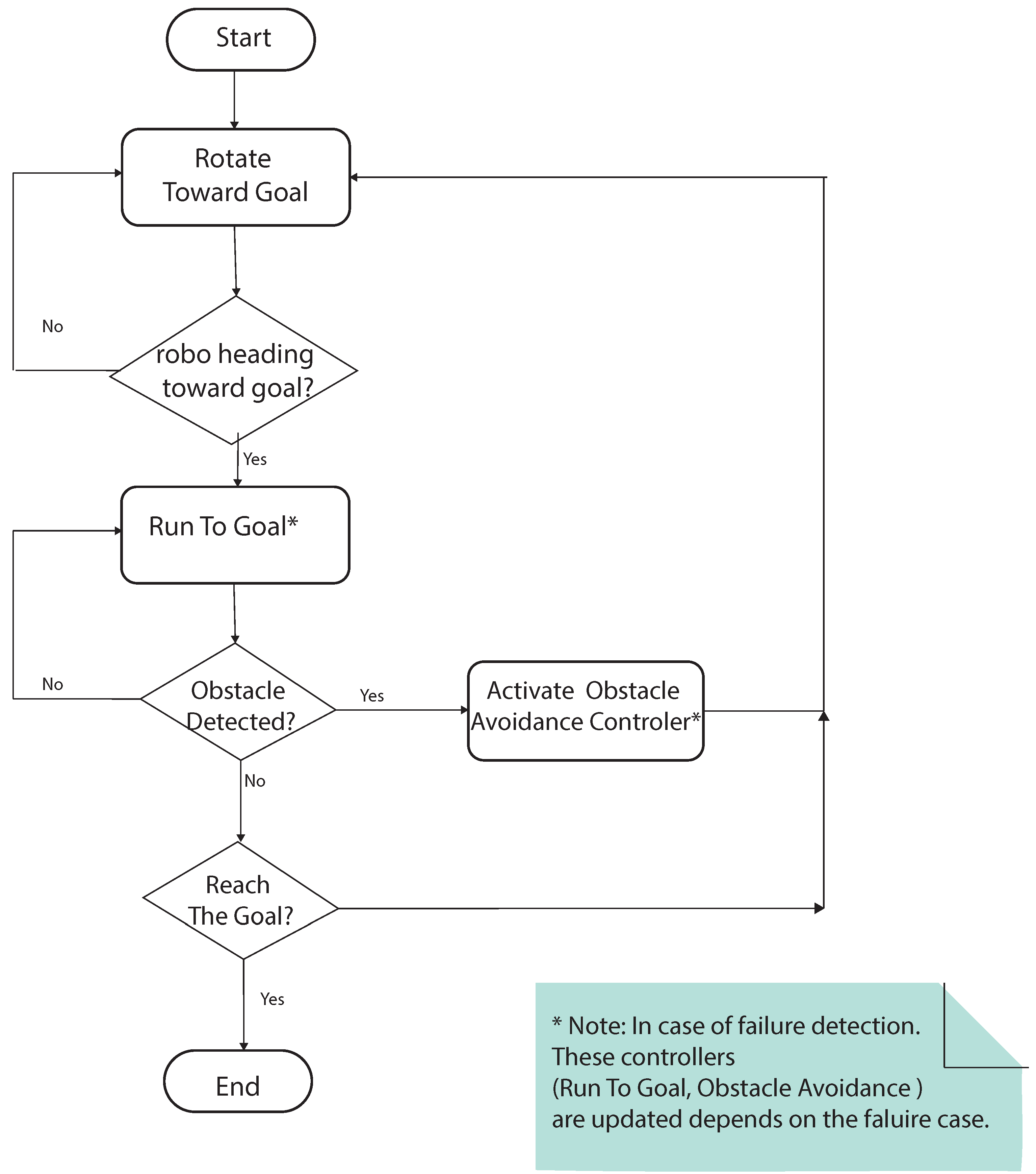
In this research, the above two problems are modified according to the health state discussed. See
Figure 3.
5. Fuzzy Fault-Tolerant Control
In this section, we discuss the fault-tolerant control strategy. We were influenced by the artificial potential field method proposed by Khatib [
9]. In his research, Khatib uses the potential filed concept to compute the total force acting on the robot. This force has two components: the repulsive force in the existence of the obstacle, and the attractive force produced by the target to attract the robot. The potential field force is created by superposing these two forces, and the only nearest obstacle is considered to reduce the computational cost. Thus, the actuation control signal for each motor is given by:
where
is a
vector with a single nonzero (
) component defines the control vector components (
) based on the states of faults discussed in
Section 4. As an example, if the FDI algorithm identified the
fault (front or left wheels have faults), then
. Each fault state has one or more fault cases; in state 3 (diagonal fault) has two cases: either the wheels 1 and 3, or the wheels 1 and 3 are faulty (both of these two cases belong to the state 3). Thus, the total number of fault cases in the five states is defined by
n (11 in our problem).
and
are vectors of the attractive and repulsive forces, respectively. Also,
is a piecewise function (to activate the obstacle-avoidance controller, see
Figure 3) and given by:
where
is a constant factor to be tuned,
is the position of the nearest obstacle to the robot (i.e., position sensors data), and
is the influence enrage of the obstacle, it can be adjusted based on the running speed of the robot and the workspace size (tuned parameter).
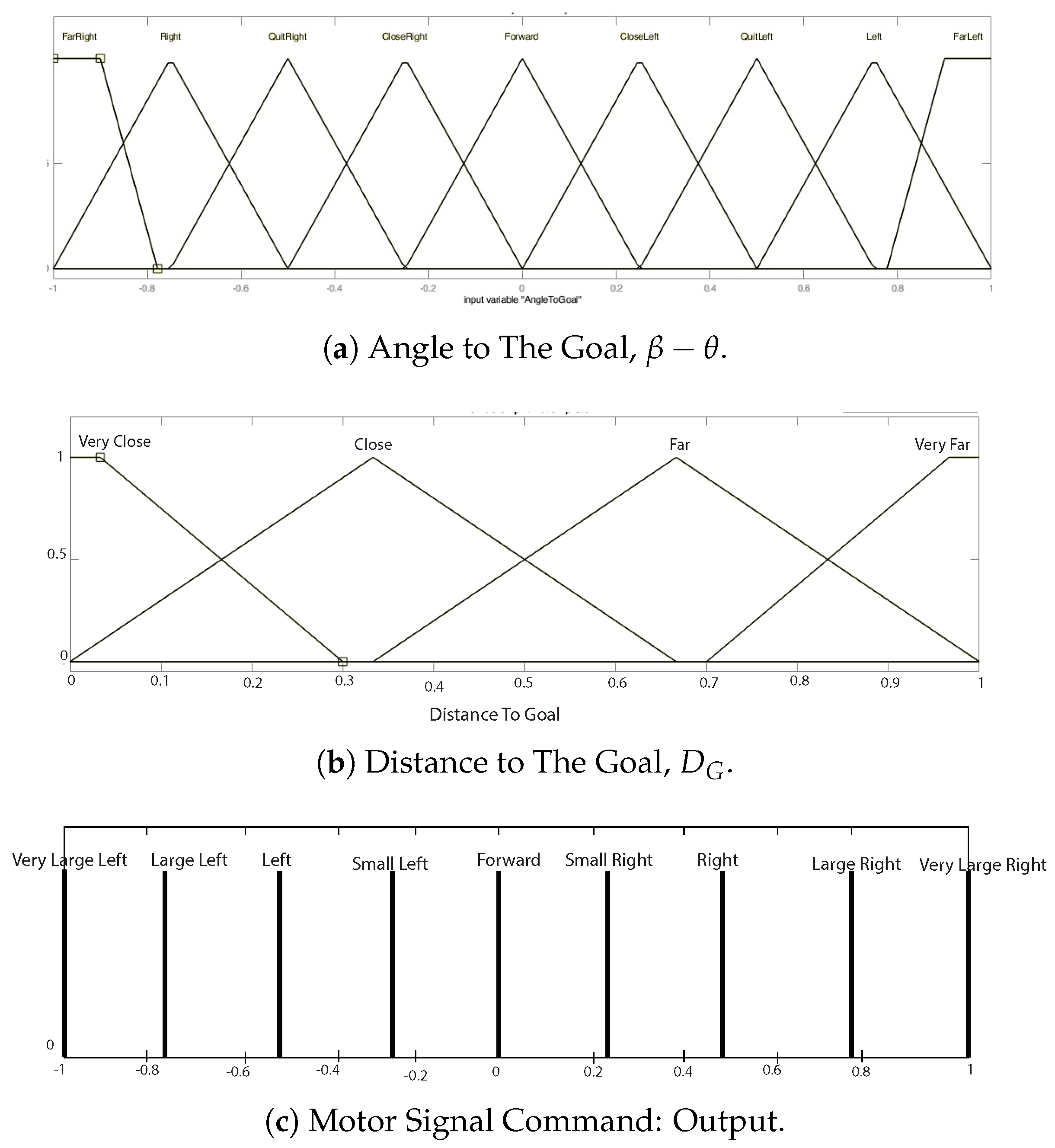
5.1. Fuzzy-Based Run-to-Goal Problem
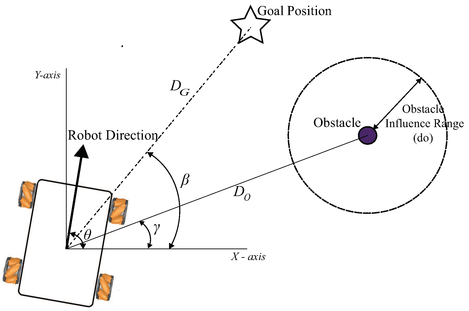
The principle of fuzzy-based control proposed by Sugeno was used to develop the Run-To-Goal controller. In this approach we have two inputs: the distance from the current position of the robot to the goal
, and the angle between the robot direction
and the angle of the straight line connecting the current position of the robot and the final goal position
, see
Figure 4. The input space is divided by fuzzy memberships; a trapezoid and symmetrical triangle shape for the membership functions were used to the fact the computation, see
Figure 5. We use nine-membership functions for the angle input
; this angle could be negative or positive depends on the position of the final goal and the robot’s orientation. Also, we use four membership functions for the distance between the robot the final goal position. The output of this algorithm is considered to be an attractive force to the final target position. We use nine-membership crisp output values. Matlab Fuzzy logic toolbox was used to build the fuzzy controller, and the fuzzy rules were created based on the prior knowledge of the problem domain. A total of 36 rules were generated to cover all possible inputs;
Table 1 shows a sample of these fuzzy rules. When there is no obstacle in the path, the robot always tries to adjust the heading angle toward the target.
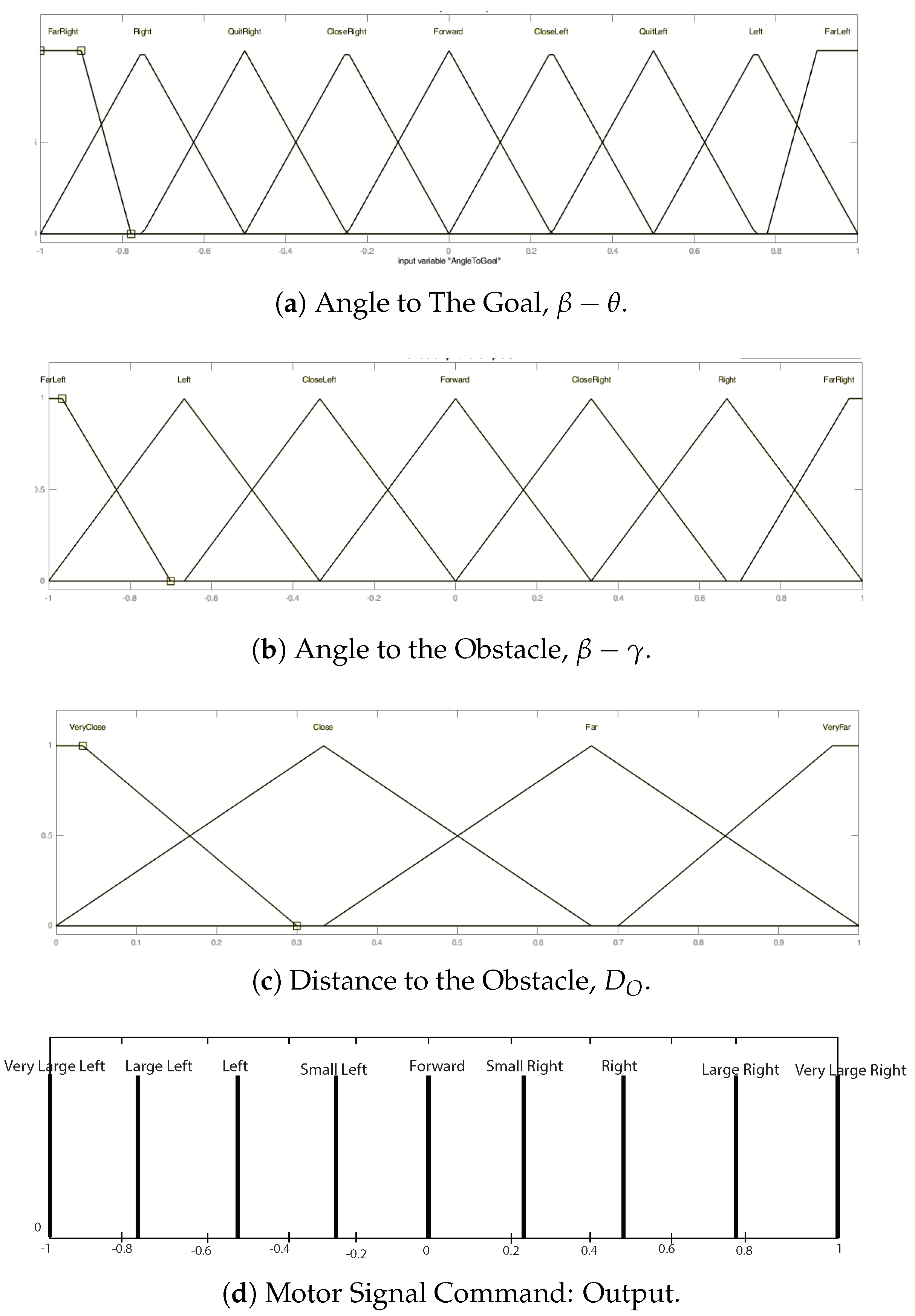
5.2. Fuzzy-Based Obstacle Avoidance
We use the fuzzy control principle by Sugeno to develop the obstacle-avoidance controller. The fuzzy model has three inputs:
The distance from the current position of the robot to the nearest obstacle
. See
Figure 4.
The difference between the robot’s orientation angle
and the angle
. See
Figure 4.
The difference between the robot’s orientation angle
and the angle
is shown in
Figure 4.
This input space is divided by fuzzy sets; trapezoid and symmetrical triangle shapes for the membership functions were used to reduce the computation efforts, see
Figure 6. We use nine-membership functions for the angle input
; this angle could be negative or positive depends on the position of the final goal and the robot’s orientation. Moreover, we use four membership functions for the distance between the robot and the nearest obstacle in its range,
. We also use seven membership functions for the angle between the robot orientation and the obstacle (
). The output of this controller is considered to be a repulsive force. For the output, we use nine-membership crisp output values. Matlab Fuzzy logic toolbox was used to build the obstacle-avoidance fuzzy controller.
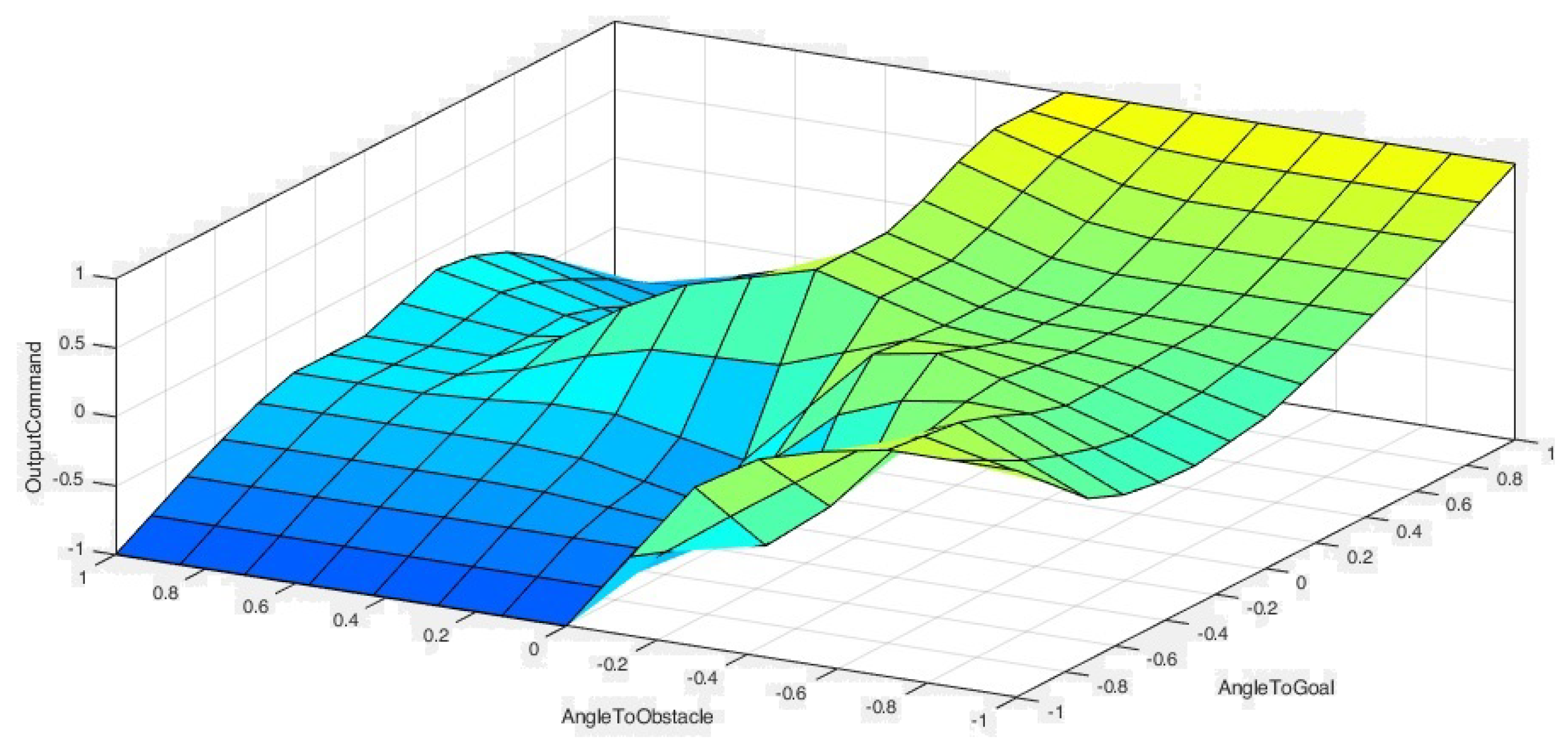
Figure 7 shows the fuzzy surface of the rules for the obstacle-avoidance controller. A total of 324 rules were generated to cover all possible input combinations.
Table 2 shows a sample of these fuzzy rules.
6. Simulation Results
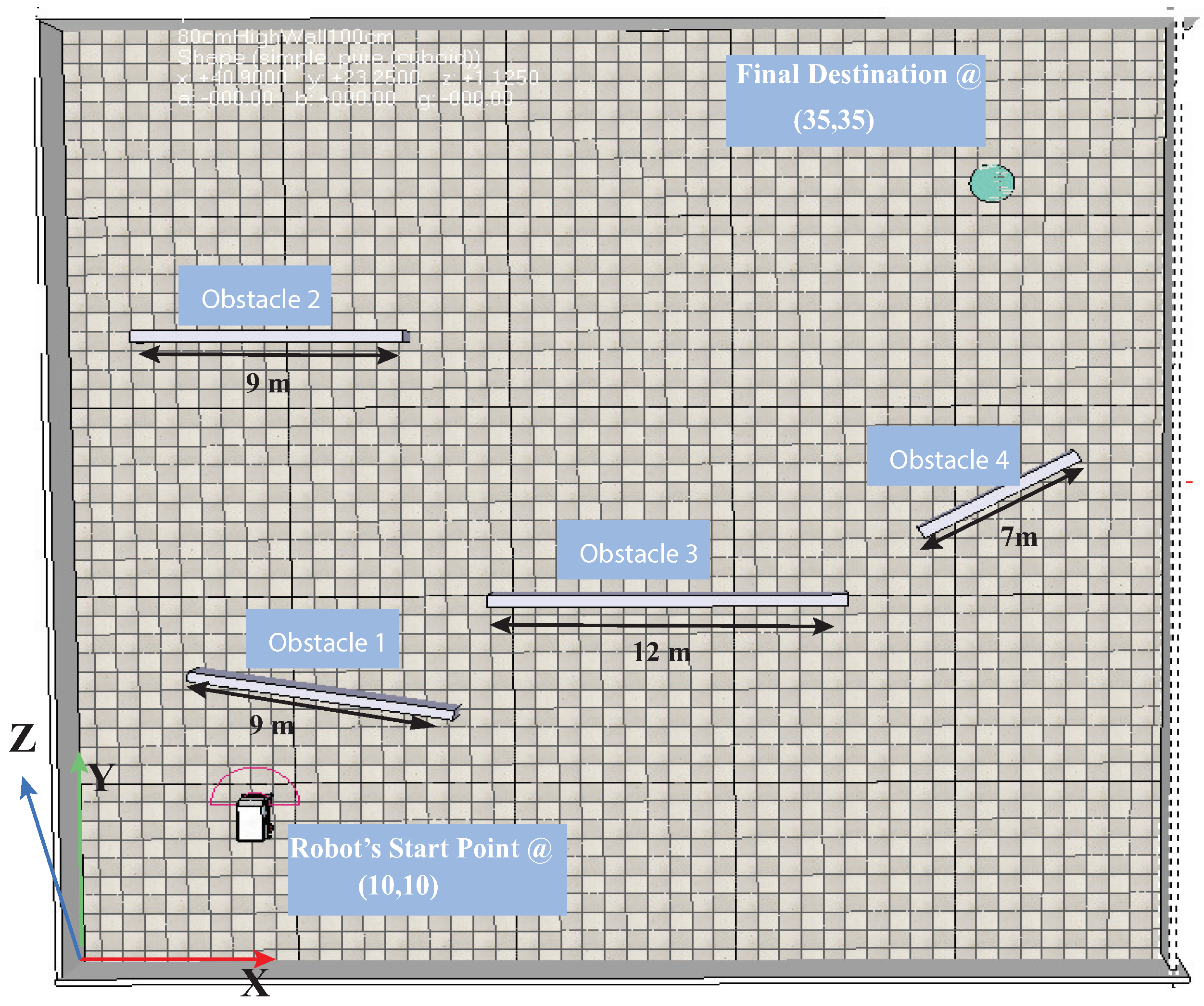
In this section, a set of simulation scenarios is presented to check the proposed fuzzy tolerant controller’s validity and performance in this paper. Matlab was used to build the fuzzy-based fault-tolerant control, and the 3D simulation was developed on the CoppeliaSim software. KUKA omniRob Model in CoppeliaSim was used as an example of the omnidirectional robot. We examine five distinct scenarios, each one with a different fault state. The goal is to reach the goal position while avoiding any obstacle in the path with respecting the workspace boundaries.
Figure 2 shows the workspace and its boundaries, the robot, four walls (Obstacles), as well as the final goal position. The position of the final destination is {35 m, 35 m}. The CoppeliaSim simulation environment communicated with the Matlab using the remote API, which allows the communication and bidirectional data streaming between the CoppeliaSim and Matlab.
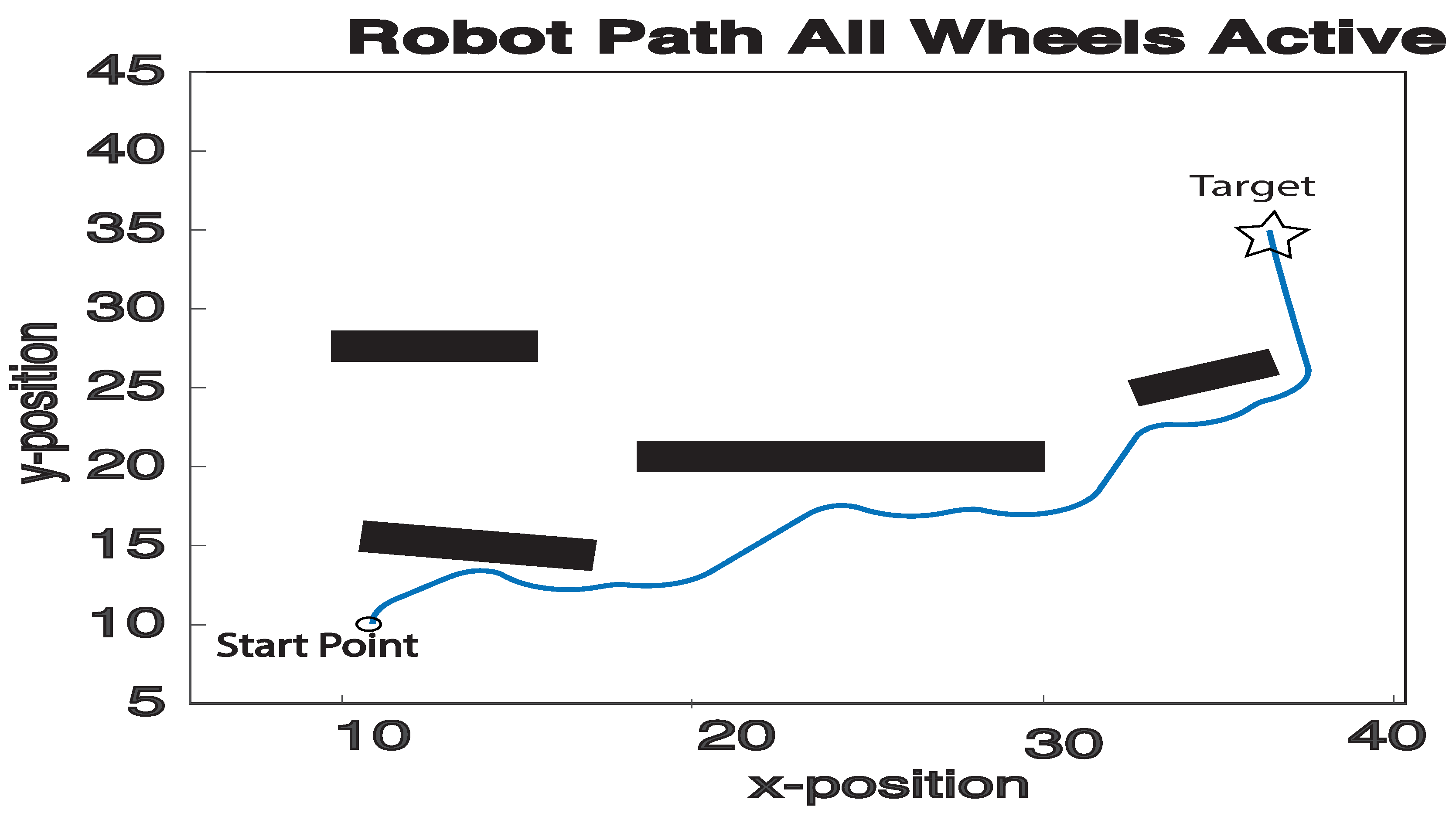
Figure 8 and
Figure 9 examine the performance of the proposed control strategy with no fault conditions (
). In this scenario, all four motors are working properly.
Figure 10 shows the robot trajectory, where the robot was able successfully to reach the final destination by avoiding the obstacle in its path. The robot could not reach the final destination with a straight line because of the obstacle in its direct path, but it could avoid the obstacle with minimal efforts needed.
Figure 10 and
Figure 11 examine the performance of the proposed control strategy with identified fault in the
(
). In this scenario, all motors work properly, but the first wheel (front-left) has a fault identified by the FDI algorithm.
Figure 10 shows the robot trajectory where the robot was able successfully to reach the final destination by avoiding the obstacle in its path.
However,
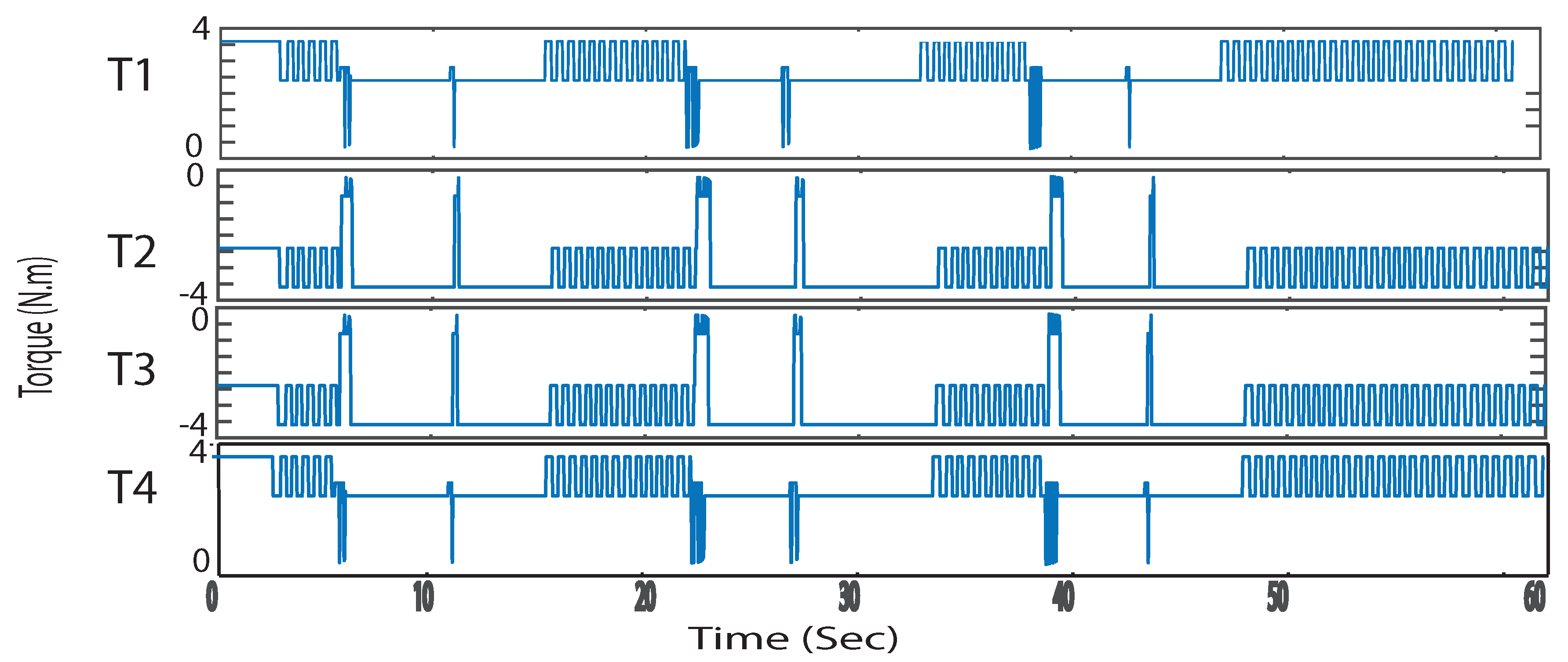
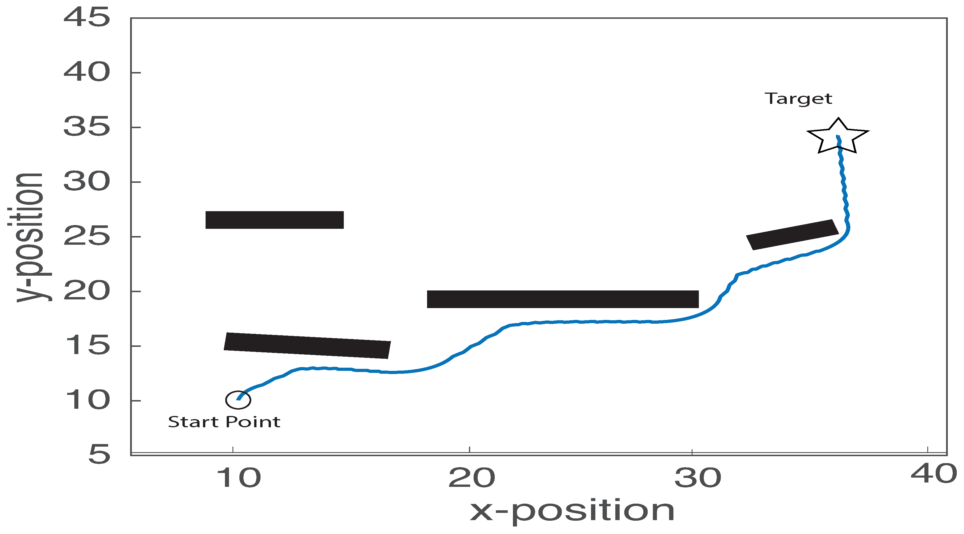
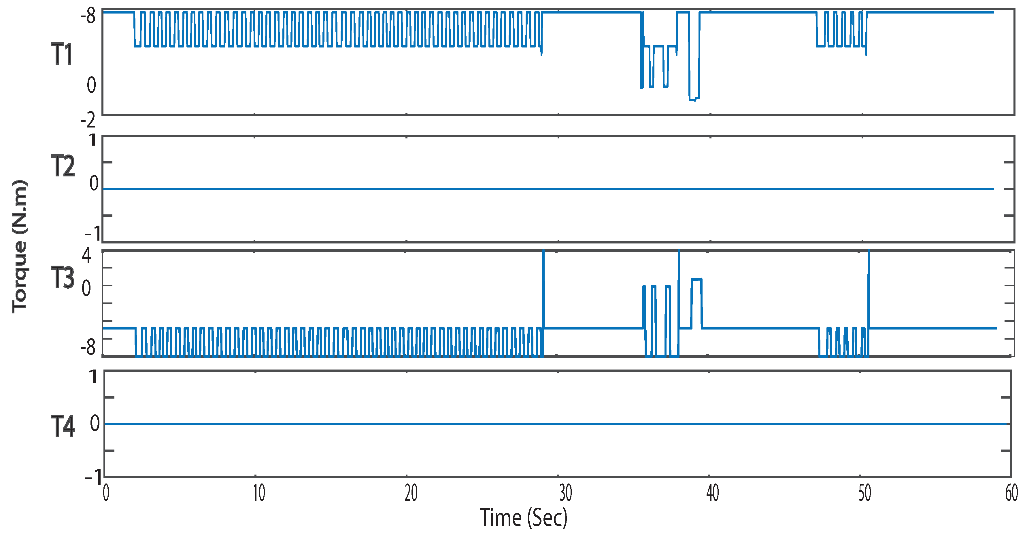
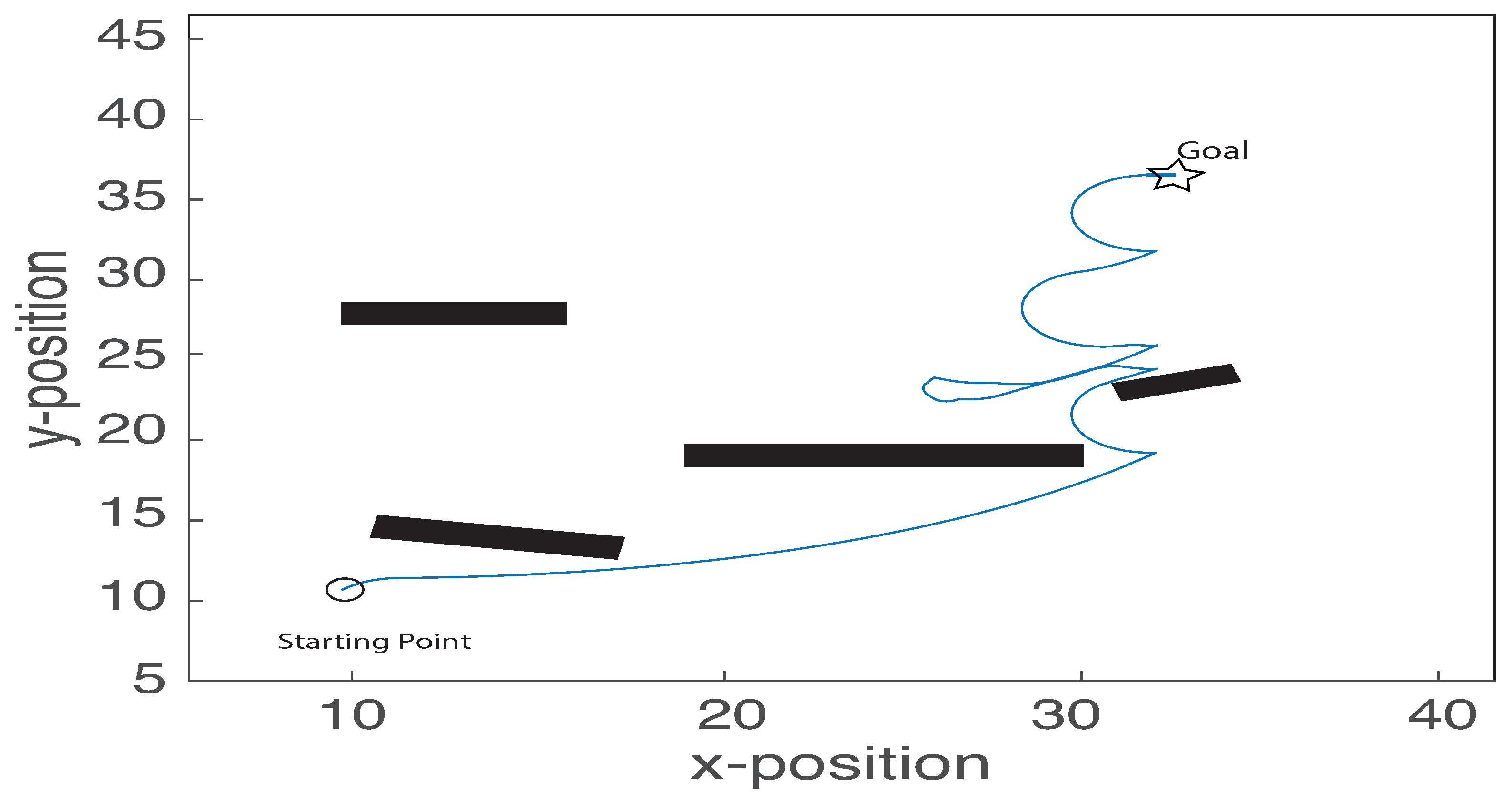
Figure 12 and
Figure 13 examine the performance of the proposed control strategy with faults on the Front-Right and Rare-Left wheels (Diagonal fault, State3). In this scenario, Only the Front-Left and Rear-Right wheels (1 and 4) can receive control signals.
Figure 12 shows the robot trajectory where it was able successfully to reach the final destination with avoiding the obstacle in its path.
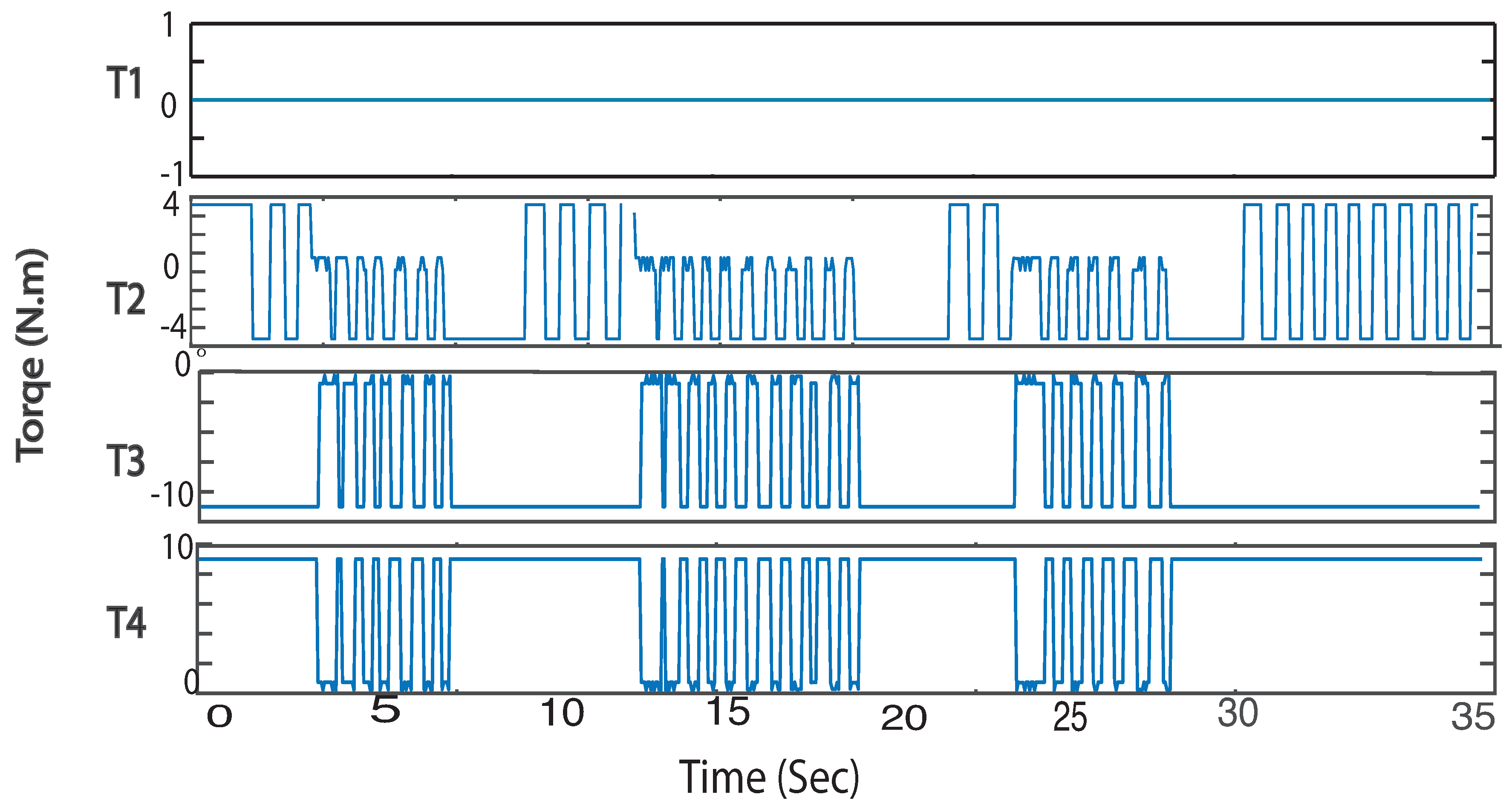
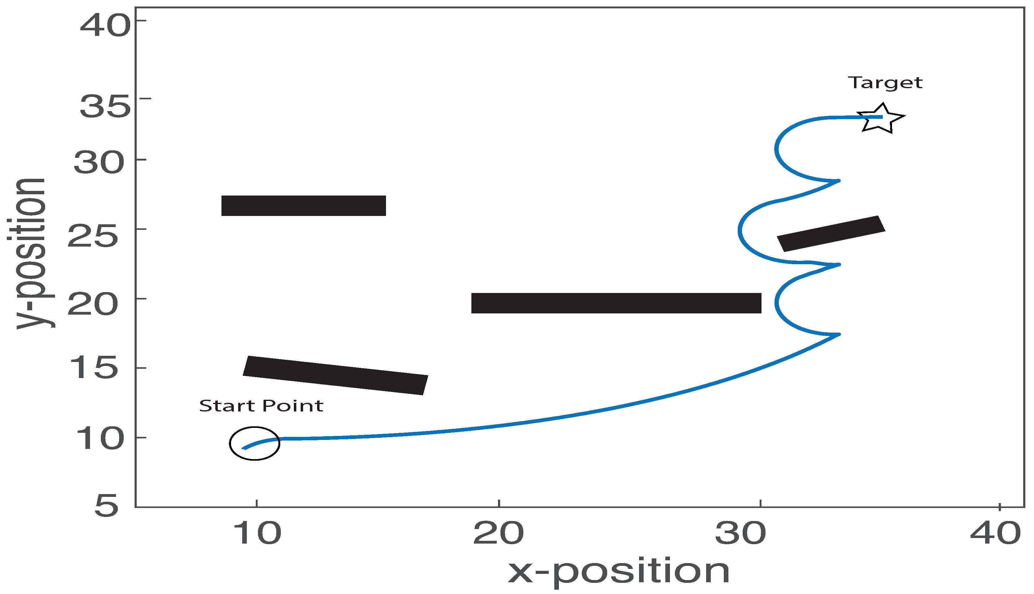
Also,
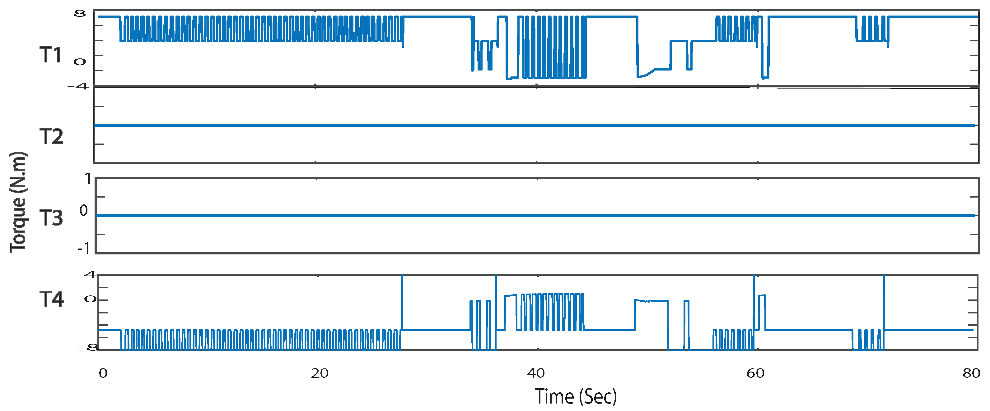
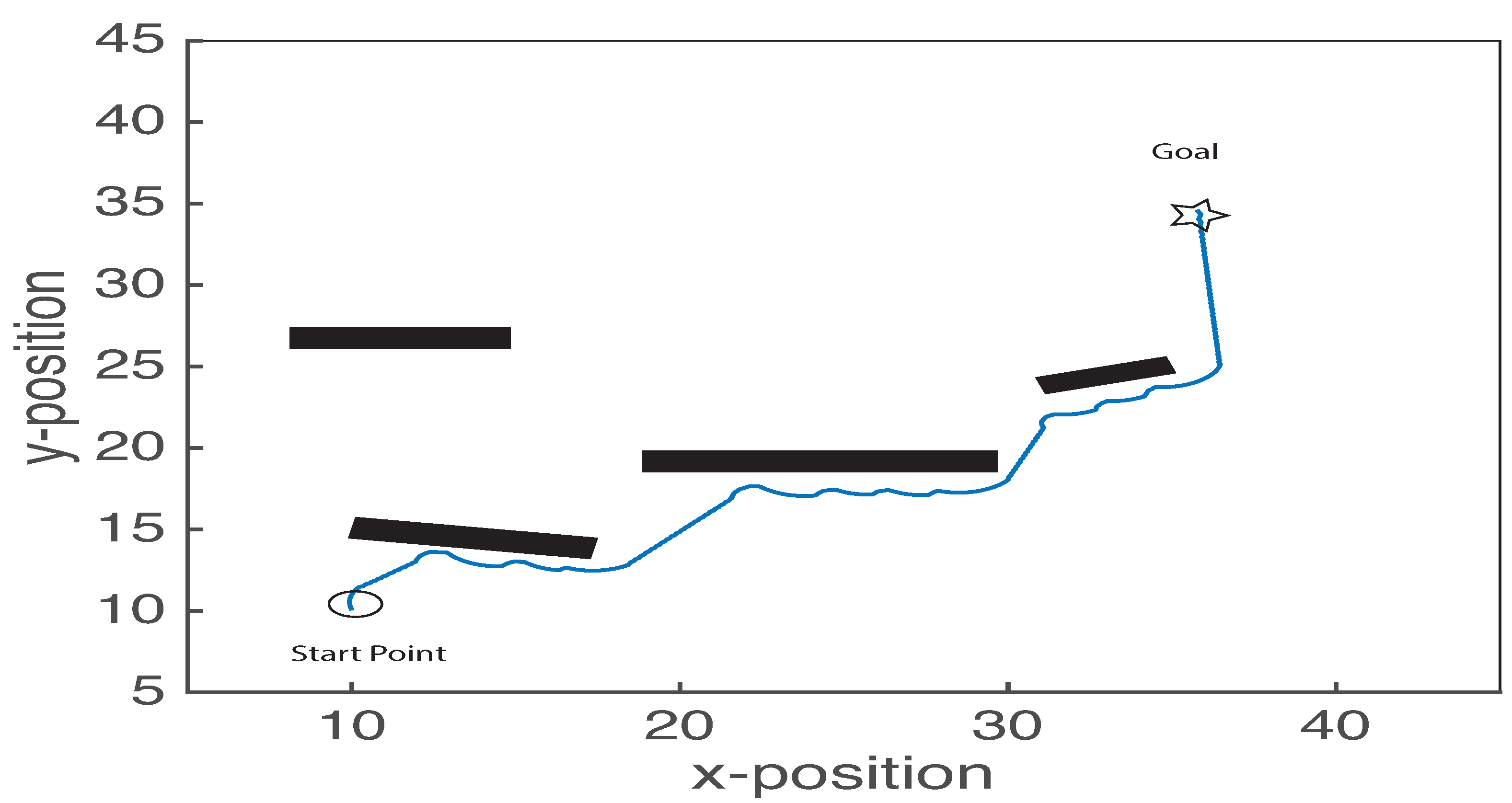
Figure 14 and
Figure 15 show that the robot can finish the desired task when the two right motors (2, 3) are not functional. In this scenario, the right motors work probably, and due to the faults in the left motor, it can be seen that the robot reach the final destination, but it was not able to go straight to the goal because of the actuation faults, it takes some time (going right and left) to reach the goal.
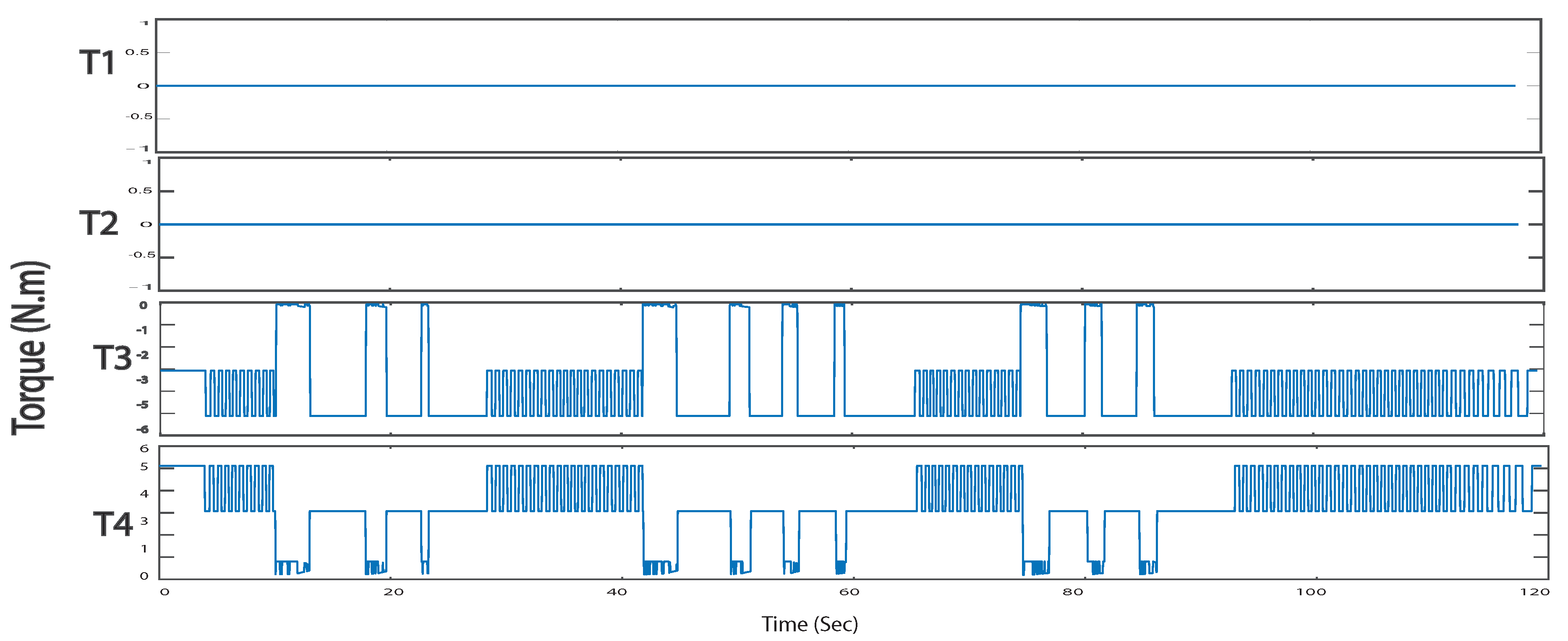
State 5, where the rear wheels are only active, the robot was able to reach the goal smoothly. See
Figure 16 and
Figure 17 that shows the path of the robot and the motors torque.
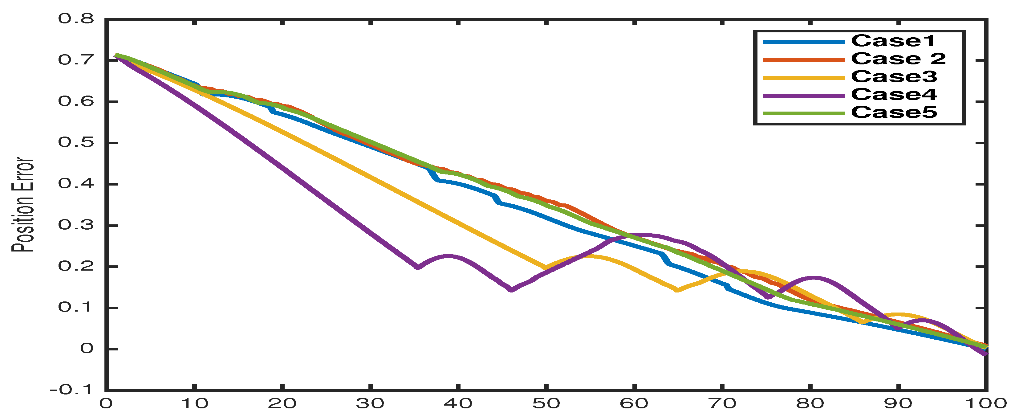
Figure 18 shows the means error of the robot positions in the five simulated scenarios. The robot starts with an error of about
at the initial position (10,10). As the robot gets closer to the destination, the error vanishes. In all scenarios, the error goes to zero after a particular time.

 ,
, 


