Abstract
In this paper, a review of the evolution of the study of cylindrical gear dynamics is presented. After a brief historical introduction to the field, the first attempts to describe the complex interactions in those systems are analyzed introducing the dynamic factor and the first methodologies used to compute it. Next, the sources of excitation in geared systems are analyzed in detail and the models of the various contributions are discussed. Then, the paper focuses on the use of those sources in several dynamic models which are wildly different in terms of scope, applicability, complexity and methodology employed, ranging from simple analytical models, to lumped masses models up to multibody and finite element models. Finally, an outlook to the future evolution of the field is given and conclusions are drawn.
1. Introduction
Gears are among the most widely used methods to transmit motion and power, and they have been so since ancient times. Probably the oldest evidence of their use is the Antikythera mechanism which dates back to the 3rd century BC and was used as an astronomical calendar. The Chinese during the 3rd century developed a chariot with a differential mechanism with gears to keep the statue of the emperor pointing south as it travelled through the country. From the ancient ages the uses of gears have multiplied exponentially and as of today their uses ranges from super-heavy machinery, down to miniaturized high-precision applications like clocks and watches. Recently [1] it has also been discovered that a small insect in its juvenile state uses a geared mechanism to synchronize the movement of its legs during jumps to maximize accuracy and distance covered as visible in Figure 1. This is the first occurrence of a natural geared mechanism ever found. Ideally gears could be considered as rigid bodies and as such, due to their properties and geometry, they should be able to transmit motion at a constant rate without introducing in the system that they’re a part of further sources of dynamic excitations.
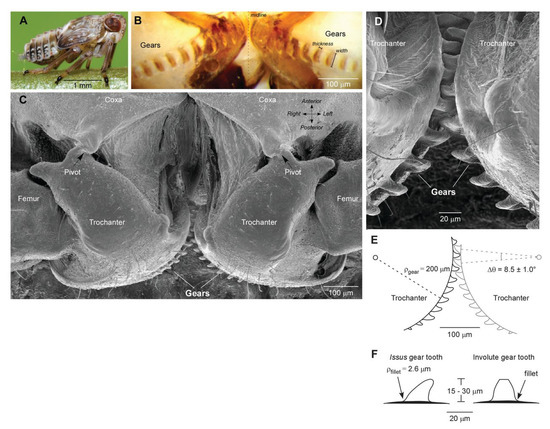
Figure 1.
Naturally occurring geared mechanism from [1].
This would mean that gears would not be sources or victims of mechanical failures, since those are most commonly caused by dynamic problems. Indeed, most of the damage mechanisms, such as fatigue and wear, and all the noise and harshness problems are due to the dynamic nature of the conditions in which the mechanical systems are operating. The large amount of literature related to engagement dynamics and gear dynamics in general ([2,3,4]) proves that this is not the case. This great amount of literature available is due to the various aspects and outputs the engineers are interested in, starting from the stresses in the gears, the cumulated damage, the efficiency of the power transmission, the noise and vibration emission and propagation, the loads on the supporting members such as the bearings and the gearbox casing, all the way to more complex problems like rotor dynamics and the final life assessment of the entire transmission. These dynamic effects are generated by the system kinematics, such as the cyclic variation of load due to gears rotation, and by the system flexibility. The first aspect could surely induce failure of the gears such as fatigue in the tooth root fillet or in the contact surface, but this is implicit in the nature of mating gears and unavoidable and therefore must be treated by a conventional fatigue approach as described in the consolidated standards like AGMA [5] or ISO [6] (Figure 2). Scientific analyses to reduce and mitigate problems related to the second aspect started in the Twenties and Thirties of the 20th century and they were related to the evaluation of the dynamic overloads due to teeth mating and studied which design changes could increase the lasting of the system by reducing noise and vibration. In the Fifties, studies were conducted to understand the overload during engagement with the help of the first dynamic models. More complex models were then introduced in order to improve their accuracy and to take into account the effects of tooth tridimensionality and the nonlinearities of the main components and also due to the effects of friction and lubrication. The increase in computational power and availability the literature is enriched by complex Finite Element (FE) and Multibody models that alsoconsider the micro and macro geometry of the gears, the overall deformations of the gearbox components and the evolution in time of the engagement. The goals of those studies also shifted with time. The earlier works are oriented towards the estimation of the Dynamic Factor which is the load increment due to the dynamics. Others are instead voted to engagement dynamics and they focus their attention on the compliance. Others are more system-oriented and they consider shaft and bearing clearances and flexibilities. With the rise of high spin speed system gyroscopic effects are also taken into account with complex rotor dynamics models of the geared system, while others are more focused on the noise and vibration aspects. This wide variety of goals and methods is justified by the objective complexity of those systems and reflects the difficulty of understanding and modeling the dynamic behavior of geared transmissions. In the early years the objective was to study and define a factor to scale the nominal forces to take into consideration the dynamics during the design of the gears, as is still done today according to AGMA [5] and ISO [6]. The first works were mostly experimental and the first definition of the Dynamic Factor was obtained by comparing the nominal conditions to failure conditions by experimentally varying the spin speed and loads of a transmission and recording ruptures [2]. Failure conditions were then compared to nominal ones and the Dynamic Factor was computed. This clear dependency of the survival of the gears with spin speed and load conditions led Walker [7] to propose the first analytical expression. In that expression the Dynamic Factor () was directly related to the tangential speed and the pitch diameter
where v is the linear speed of the gear at the pitch diameter in feet per minute. This approach overestimated the dynamic contributions since it neglected a lot of parameters. A modification, which became the starting point for the AGMA standard [5], was proposed in [8]:

Figure 2.
Tooth bending strength calculation as detailed AGMA [5] and ISO [6]. For an explanation of the depicted quantities, the reader is referred to the cited standards.
The AGMA standard will later take into consideration the manufacturing quality in the expression of the Dynamic Factor :
where , and is the transmission accuracy level. Tuplin [9] was the first to consider the errors due to gear manufacturing. He defined a natural frequency of the resonance phenomenon that could occur in a gear pair when a pitch error is present and the maximum load that the gear pair could experience. A sketch of this model is visible in Figure 3 and the accelerations and can be computed solving the equations of motion where the external load is represented by the time variation of the distance between the gear and the stiffness k. Tuplin finds that the maximum load cannot exceed the value of the stiffness times the pitch error e. Harris [10] conducted a series of tests to understand the causes of gear vibration. Harris analyses the relative displacement as the variation in the velocity ratio at the pitch diameter for different gears and loads. He finds that the relative displacement at a precise load is strictly related to the static error at that loads and the curves he registers in the so called Harris map (Figure 4) are only related to the variation in stiffness. He therefore introduced the concept of the design load which corresponds to the particular torque for which the mesh excitations of a given gear are minimal. His findings were confirmed by numerous experiments and also proven theoretically for pinion-gear pairs ([11,12]) and for multi-mesh systems [13], thus the importance of the Transmission Error ( see Figure 5) was highlighted. If the gears are considered rigid, they form a perfect kinematic coupling and therefore the displacements along the line of action of the two mating gears are equal, so
where , represent the base diameters of the two mating gears and , their angular displacements. In actual conditions, teeth are flexible, profiles are different from ideal and due to manufacturing and assembly errors the above relationship does not hold anymore. Therefore, the following general definition for the TE can be stated

Figure 3.
Tuplin’s proposed dynamic model, as described in [9].

Figure 4.
Harris map [10].
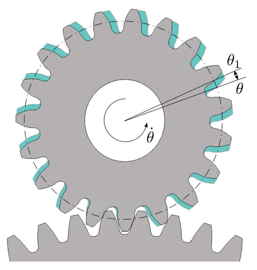
Figure 5.
Visualization of TE: in grey the ideal position, in cyan the actual one.
If conditions can be considered static or quasi-static, this TE is often called Static Transmission Error () or equivalently Loaded Static Transmission Error (). Several approaches have been proposed throughout the years to analyze the ranging from experimental methods ([14,15,16]), analytical ones ([17,18,19]) or adopting the flexibility and accuracy of the FE method ([20,21,22,23]). When the is computed taking into considerations only the modifications from the ideal gears due to the manufacturing process then it is called Manufacturing Transmission Error () ([24,25,26,27,28,29]). Those errors can be of shape, of pitch deviations or indexing and run-out. When the mounting deviations such as center distance variation, eccentricities and misalignments but no loads are acting on the system then that is called the No Load Transmission Error () as described in [30]. Furthermore, due to dynamic effects, the instantaneous load changes and teeth could even lose contact and even have impacts on the coast side of the tooth profile and during rotation all of the above mentioned errors cumulate and the Dynamic Transmission Error () originates, which is hence a function of time, that can be expressed as
During the 1980s, Japanese researchers and engineers conducted several important experimental studies on torsional dynamics of gears including analyses of gear errors and profile modifications providing a solid groundwork for subsequent studies ([31,32,33,34,35,36,37]).
2. Sources of Excitation
2.1. Transmission Error
Evidently, the calculation of those errors, especially the , is crucial in understanding the dynamic interaction in geared systems and obtaining the correct Dynamic Factor and the . The first works in this direction were based on analytical formulations and the first one is by Weber [38] and later by Weber and Banaschek [39]. These works are based on the superposition of the deformation due to the contact between teeth, the deflection of a clamped-free beam with the shape of the tooth and the ring compliance. The compliance due to contact between teeth is analyzed using the bidimensional Hertz theory [40] for cylindrical contact, while Lundberg [41] proposed to consider a distribution of pressure at the surface of an elastic half plane. The clamped-free variable shape beam introduces the flexural, shear and normal compliances. The gear body is accounted for considering the tooth rigid and assuming the ring as a large elastic plane where flexural, shear and normal effects are applied. Ishikawa [42] improved the methodology by considering the tooth as a trapezoidal beam attached on top of a rectangular beam. Attia [43] introduced some modifications to Weber’s model and a sketch for its application is visible in Figure 6.
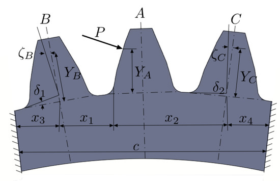
Figure 6.
Sketch of Attia’s model as defined in [43].
Its main contribution is the inclusion of the deflection of the teeth close to the loaded one in the calculation of the static solution. Cornell [44,45] later used a discrete approach instead of Weber’s integral approach to improve the feasibility of a computer implementation. O’Donnel [46] improved the model by implementing influence coefficients in the evaluation of tooth base stiffness. More recently, Sainsot et al. [47] modified the approach to the compliance of the tooth base from the semi-infinite plane of Weber to a semi-analytical formulation based on elastic rings which results in a comprehensive formula. Other authors propose semi empirical models to describe the stiffness variation during the motion of the gear, such as the work of Cai and Hayashi [48,49]. In this paper, the stiffness of the tooth is described as a function of time and contact ratio and the main parameters are the spin speed of the gear and the number of teeth that are contemporarily mating. For helical gears, Umezawa et al. ([50,51]) observed a logarithmic relationship between the stiffness and the position along the tooth face, and later Cai [52] proposed an improved function for the stiffness considering the contact ratio and addendum modifications. As the computational power increased, many researchers started using the FE method, initially to compute the stress in the root fillet, but in [53] the FE was used instead to evaluate the dynamic behavior of the gear pair. An interesting validation of the FE approach is given in [54]. In that paper a comparison of 3D FE with experiments and other base theories is given. From that time many researchers started using FE analyses to calculate the stiffness of the teeth. Some of those consider only the effect of the tooth stiffness neglecting the contact, so the FE model is only related to the structural behavior of the tooth as in [55,56,57]. Others consider separately the summation of Hertzian phenomena and the elastic behavior of the gear ([58,59,60,61,62,63,64]). An in-depth literature overview of the use of FE in the simulation of gear drives is given in [4]. Interestingly, Parker et al. [65] introduced a detailed semi-analytical contact mechanics model close to tooth surface, matched to a FE model of gear teeth and body that closely captures the non-linear dynamic response of spur gears, and another hybrid approach is presented in [66]. The effects of profile and lead modifications was investigated for helical gears in [26,67], where it was found that the meshing process can be modified by those since they affect the contact lines in the base plane and also the quality class of the gear was considered. Houser et al. [68] experimentally verified the strict correlation between the and the noise and vibration levels generated in operation. This relationship led researchers to minimize this source, first by investigating the corner contact [69], then suggesting algorithms to obtain the optimal microgeometries [70,71]. Other attempts at controlling the microgeometry can be found in [72,73] for the improvement of the load distribution along the tooth flank, and in [74] to reduce the overloads. Recently ([75,76,77]) a set of analytical formulas was proposed which defines the optimal set of linear tip relief for spur and helical gears which minimizes the variance of the . The wide literature around these aspects highlights their importance and indeed Wang ([78,79]) analyzes the effects of backlash and the in lightly loaded high speed gears. He concludes that “the backlash alone is not a source of trouble, but backlash coupled with transmission errors can be”. In [80] a study related to gear vibration is carried out using an analytical approach, considering the tooth stiffness variable along the tooth height and the position of the external force moves according to the engagement process.
2.2. Other Sources
While is the dominant source of excitation in geared systems, other phenomena also contribute to the overall dynamic behavior. One of the most easily recognizable secondary sources is the fluctuation of the torque, which in automotive gearboxes can generate vibro-impacts and therefore rattle noise [81] as experimentally investigated in [82]. Wind turbines suffer torque oscillations due to the unsteady aerodynamics [83] as well as vacuum pumps due to low fluidic drag torque interactions [84]. Interestingly, in [85], a model utilizing adaptive selection of the time-step is proposed to take into account both rotational velocity and torque oscillations highlighting the fact that the resulting is not only dependent on the instantaneous stiffness but also greatly affected by the rotational speed with wildly different impacts for the different sub-harmonics. Friction in the engagement also plays a non-negligible role since the relative sliding velocity changes as the contact point passes through the pitch point possibly increasing gear vibration [86]. A method to consider friction in the calculation of the mesh stiffness is shown in [87], while its effects as an excitation source are especially evident along the off-line-of-action direction as highlighted in [88,89]. Manufacturing errors not only influence the and hence the , but are directly involved in the dynamics as experimentally shown in [90] and more recently in [91], while the effect of shaft balancing, positioning and alignment of the gear pairs has been analyzed in [92]. For helical gears the centroid of the normal force moves across the facewidth causing a shuttling moment [93] which can be a further excitation as can be the electromagnetic forces [94] in the increasing number of electric vehicles, showing that for a comprehensive analysis also secondary phenomena can play an important role as excitation sources.
3. Dynamic Models
3.1. 1D Models
In the years between Tuplin’s [9] work and that of Bahgat et al. [80], a great number of studies were conducted and the extensive review by Ozguven and Houser [2] was surely the starting point for the model presented in [95] (Figure 7), which is similar to the one in [51] but makes a distinction between and and uses the former to compute the latter and was validated on the experimental results of dynamic root strains recorded in [96]. Using a similar model, Kahraman and Singh in [97] (Figure 8) study the dynamic behavior of a gear pair simplifying some aspects. For example, the is modeled as a sinusoidal quantity that varies with its own frequency and the fluctuation of the torque is characterized by a fundamental frequency different from the one of the , and those fluctuations make up the excitation sources. However, it introduces a non-linear trend of the elastic contribution to the force equilibrium, which is equal to zero when the displacement measured along the line of action is between the values of the backlash and is linear otherwise. The equation of motion for this model can be written as
where the equivalent mass is obtained from the inertias and of the pinion and gear respectively and their base radii and , is the mesh stiffness, is the static torque, c is proportional damping, is the and is the excitation source described above. Instead, in [65] a similar model is proposed but in this case the external excitation source is not present and the excitation comes from the fluctuation of one of the parameters, namely the Time Varying Mesh Stiffness () computed from the at different torque levels. Thus, the parametrically excited system equation of motion can hence be written as
which highlights the different approach used to simulate the nonlinear behavior of meshing gears. Kahraman and Singh later improved their model [98] by taking into account also the compliance of the shafts and the clearances in the bearings as well as the periodic variation of the mesh stiffness as a source term. Blankenship and Kahraman [99] later developed a test rig to verify the numerical results and they find that if a non-linear jump phenomenon occurs, its jump-up frequency is independent of the load applied, while the jump-down frequency lowers as the load vanishes.
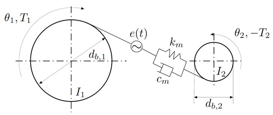
Figure 7.
Ozguven and Houser dynamic model as detailed in [95].

Figure 8.
Nonlinear trend of the elastic contribution as described in [95].
A similar model can be found in [49], but they explicitly state the error contributions, and they are able to linearize the equations and express the error function in Fourier’s series considering the effect of contact ratio and errors on the dynamic response of the gear pair. They then demonstrate that the presence of subharmonics in the response is mainly due to the error harmonics. Profile errors were also simulated in [100] using a digitized approach to include their effect in the dynamic response showing possible increases in dynamic loads due to contact loss caused by those errors. Rather than focusing on the line of action, a rotary model was developed by Yang and Sun [101] which also introduced the alternation of the number of tooth pairs in contact. In [102] the authors provide a detailed description of flank modifications, deviations from the theoretical one and mounting errors resulting in a general definition of the , which was first investigated in [103]. They apply this methodology on a system in which each gear is represented by six degrees of freedom, and it proves to represent well enough a unified approach. Amabili et al. [104] proposed a modified non-linear model that takes into account also the non-linearity in damping and for its description they use the same approach as for the stiffness and also a method to identify important dynamic parameters by the vibration of spur gears [105], while the contribution of composite manufacturing errors in the dynamic response was highlighted in [106]. NASA [107] published a report implementing the state of the art and focus on a parametric evaluation of the dynamic overload with respect to the contact ratio highlighting its importance in ruling gear dynamics. Kahraman and Blankenship ([108,109]) experimentally investigated the relationship between the contact ratio and the magnitude of the dynamic overload and also the one between mesh stiffness variation and contact ratio. One of the first works that employs FE to evaluate gear dynamics is [110] in which different models of increasing complexity are studied and the influence of the engaging shifting due to teeth compliance on the dynamic overload is underlined. An interesting work focused on damping and friction was published by Vaishya and Sing in [111] and later in [112]. They consider the friction coefficient as an explicit function of time by taking into account the instantaneous sliding velocities between the surfaces due to the kinematics and the vibration. They highlight that friction damping is present also at pitch point where theoretically no sliding effects are present and that the absence of instabilities in most practical applications is due to this effect, but that this friction effect is a source of excitation for out of line actions. A further model improvement was published in [113], where the effects of profile modifications, backlash, tooth separation, mesh and bearing damping were included. In [114], Theodossiades and Natsiavas consider the time-dependent mesh stiffness not as an external excitation, but as an intrinsic time-varying parameter of the system and they study the system’s response with analytical and numerical methods analyzing the effects of backlash, damping and other parameters on the response and stability in several conditions highlighting the possibility of occurrence of crises and intermittent chaos for this kind of systems. The same researchers then improved their model [115] including the non-linear characteristics of oil journal bearings and also proposing a reduced order model to take into account also the flexibilities of the shafts and their rotordynamic behavior showing that several possible branches of unstable periodic response are possible. Another approach detailed in [116] introduces nonlinearities also from bearings and by only specifying the external loads the existence of other chaotic phenomena is demonstrated. Potential instabilities were also studied in detail in [117,118,119] with different approaches such as the phase-plane and state-space methods.
3.2. Advanced Models
Parker and Vijayakar [65] (Figure 9) removed the need to provide the mesh stiffness as in input by coupling a FE model with a detailed analytical contact model whose results got a close agreement with experimental data on the dynamic response of spur gears and was also compared to experimental tooth root strains in [120].
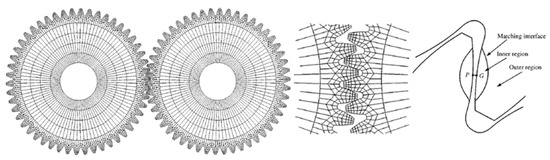
Figure 9.
Coupled FE/Contact mechanics model from [65].
The same method was later extended to the frequency domain in [121]. This approach was even employed to applications in planetary gears [122] and experimental comparisons can be found in [123] also against simpler lumped parameters models. Further improvements to the method were introduced in [124,125,126] where the effects of compliant ring and sun gear was studied and it was shown that a higher flexibility of those components can improve the load sharing on the planets and the overall dynamic response. The effects of the presence of rolling elements was investigated in [127] using the same approach and comparing the results to those from a perturbation analysis. Improvements to reduce the computational effort were introduced in [128,129] still considering several sources of non-linearities and the influence of flexibilities and also the effects of tooth profile modifications [130]. This model was the base upon which the Hybrid Analytical–Computational model was developed in [131]. The authors precompute a Force Deflection Function (Figure 10) for various loads and apply that to a lumped parameters model obtaining extremely accurate results at a fraction of the computational time required by more complex analyses.
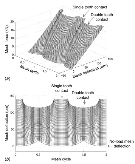
Figure 10.
Force Deflection Function from [131], (a) 3D view, (b) frontal view.
Cooley and Parker also introduced an approach to the simulation of flexible gears by modeling a rotating elastic ring coupled to constant space-fixed foundations ([132,133]) and a study on the parametric instabilities was later conducted introducing fluctuating values of the mesh stiffness [134]. The analytical nature of their model allows them to derive closed-form solutions for the eigenvalues including rotor dynamics effects and study in detail veering and instability phenomena. An interesting paper from Cooley et al. [135] analyzes two different methodologies to compute the mesh stiffness during the engagement and their appropriate use as input in lumped parameters or FE dynamic models (Figure 11). The first one is the average slope approach and it implies the calculation of the mesh stiffness by simply dividing the load by the deflection during engagement:
where and is the tooth mesh load. In this expression the loaded from Equation (5) can be recognized and is the . The local slope approach contemplates the following instead:
where is a small variation in the mesh deflection. The authors find that using the average slope approach is correct for static analyses, but is incorrect for dynamic studies, where the local slope approach should be used instead, thus formulating the equations of motion as
where is the equivalent mass of the system and therefore the excitation depends on the which takes into account both the mean and the fluctuating components of the mesh stiffness. Hotait and Kahraman [136] went back and tried to experimentally deepen the understanding of the relationship between the and the . They recorded for different torques and speeds the as the ratio between the tooth root strain under dynamic conditions and quasi-static ones (Figure 12):
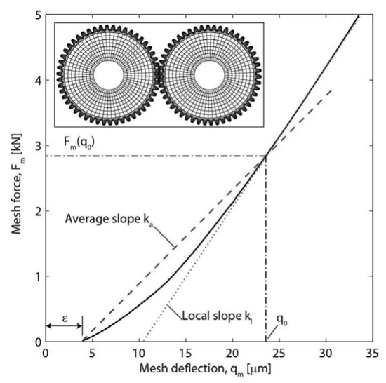
Figure 11.
Average and Local slopes for the estimation of the mesh stiffness from [135].

Figure 12.
Static and dynamic tooth root strains during engagement from [136].
At the same time, they recorded the and found a strong relationship between the two factors finally formulating a linear relationship between them, allowing the estimation of one by knowing the other. Palermo et al. [137], starting from [65], proposed a scalable multibody model for spur and helical gears based on an instantaneous contact solution and considering also the effects of misalignments. Particularly interesting is the description of the shuttling, that is axial fluctuations due to mounting deviations, and its effects on the bearings loads and the dynamic moments along the plane of action. Lim and Singh ([138,139,140]) analyzed in detail the literature regarding the inclusion of the housing in the global dynamic response and coupled the gearbox assembly with its gears and rolling elements to study the overall response. Rigaud and Sabot used a FE model of the gearbox [141] and showed the effects of the inclusion of all components of a gearbox, such as shafts, bearings, couplings and external inertias, on the overall dynamic response. In [142], a detailed FE model of the gearbox was used to its vibroacoustic response, but the dynamics of the gears was decoupled from the FE and only later the excitation through the bearings was applied to the casing. Instead in [143] the dynamics of the gears and the housing was coupled directly by a FE/contact mechanics model. In statics the rolling elements of the bearings were described in detail, while in dynamics they were included as an equivalent lumped-parameter model to reduce their otherwise enormous computational cost.
4. Future Perspectives and Conclusions
In the most recent years, the development of methodologies has not slowed down mainly thanks to the increasing interest in this field coming from the aviation and wind turbines industry, which aims at constantly increasing the power density and reliability of the gearboxes, and from the progressive electrification of vehicles thus increasing the importance of the gearbox generated noise, since in some cases the electric engine is now quieter than the reduction gearbox. This renewed interest has led to development of advanced and complex models, which now can simulate also the effects of the Bearing Time-Varying Stiffness () [144] and also the non-inertial conditions in which the gearing operates [145] which cause diverse nonlinear phenomena. Hybrid FE have been specially developed to simulate the main components of the gearbox, including the housing, with an integrated tooth contact analysis as in [146] and also several chaotic phenomena have been studied considering several clearances in [147] and even the has been made dependent on the instantaneous dynamic mesh force in [148] to further improve accuracy of the results. To further improve the accuracy of the calculation of the , the stiffness and damping contribution of the oil film during engagement are taken into account in [149], while the interaction between friction and is studied in [150]. Alongside those advanced models, several multibody approaches have been developed to reduce the computational times while retaining a good degree of accuracy, such as [151] in which the need to precompute quantities usually treated as inputs, such as the and the is removed, or using different model order reduction techniques such as [152] or [153]. Several attempts have also been made with the goal to minimize the variation of the such as [154,155] and also for the bending stress in dynamic conditions in [156]. Some focus has also been shifted to the predesign phase of the engineering process to design a gearbox by introducing quicker, yet reliable, results for example using a block-oriented approach as in [157] or with the application of the harmonic balance method in [158]. In this context an efficient method with a 3D Non-Hertzian contact model has also been proposed ([159]) and applied for different profile modifications in [160] also detailing the effects of torque inversion during operation. More than one hundred years demonstrate that the study of gear dynamics is still a challenge and an interesting field of investigation. Further research has to be done to understand the numerous phenomena at play in geared systems. This review highlights that the gear dynamics topic has not covered all issues, especially in solving the relationship between fatigue life of an actual component and the predicted dynamic response and the connection between and .
Author Contributions
Conceptualization and resources, F.B. and C.R. All authors have read and agreed to the published version of the manuscript.
Funding
This research received no external funding.
Conflicts of Interest
The authors declare no conflict of interest.
Abbreviations
The following abbreviations are used in this manuscript:
| FE | Finite Element |
| DF | Dynamic Factor |
| TE | Transmission Error |
| (L)STE | (Loaded) Static Transmission Error |
| MTE | Manufacturing Transmission Error |
| NLTE | No Load Transmission Error |
| DTE | Dynamic Transmission Error |
| TVMS | Time-Varying Mesh Stiffness |
| BTVS | Bearing Time-Varying Stiffness |
References
- Burrows, M.; Sutton, G. Interacting Gears Synchronize Propulsive Leg Movements in a Jumping Insect. Science 2013, 341, 1254–1256. [Google Scholar] [CrossRef]
- Ozguven, H.N.; Houser, D.R. Mathematical models used in gear dynamics—A review. J. Sound Vib. 1988, 121, 383–411. [Google Scholar] [CrossRef]
- Abersek, B.; Flasker, J.; Glodez, S. Review of mathematical and experimental models for determination of service life of gears. Eng. Fract. Mech. 2004, 71, 439–453. [Google Scholar] [CrossRef]
- Prasil, L.; Mackerle, J. Finite element analyses and simulations of gears and gear drives a bibliography 1997–2006. Int. J. Comput. Aided Eng. Softw. 2008, 25, 196–219. [Google Scholar] [CrossRef]
- Fundamental Rating Factors and Calculation Methods for Involute Spur and Helical Gear Teeth; AGMA: Virginia, VA, USA, 2001.
- Calculation of Load Capacity of Spur and Helical Gears; ISO: Geneva, Switzerland, 2006.
- Fisher, A. Factors in Calculating the Load Carrying Capacity of Helical. Machinery 1961, 98, 545–552. [Google Scholar]
- Ross, A.A. Tooth Pressures for High-Speed Gears. Machinery 1927, 34, 110–112. [Google Scholar]
- Tuplin, W.A. Gear tooth stresses at high speed. Proc. Inst. Mech. Eng. Part C J. Mech. Eng. Sci. 1950, 163, 162–167. [Google Scholar] [CrossRef]
- Harris, S.L. Dynamic loads on teeth of spur gears. Proc. Inst. Mech. Eng. Part C J. Mech. Eng. Sci. 1958, 172, 87–112. [Google Scholar] [CrossRef]
- Velex, P.; Ajmi, M. On the modelling of excitations in geared systems by transmission errors. J. Sound Vib. 2006, 290, 882–909. [Google Scholar] [CrossRef]
- Velex, P.; Ajmi, M. Dynamic tooth loads and quasi-static transmission errors in helical gears- Approximate dynamic factor formulae. Mech. Mach. Theory 2007, 42, 1512–1526. [Google Scholar] [CrossRef]
- Velex, P.; Chapron, M.; Fakhfakh, H.; Bruyère, J.; Becquerelle, S. On transmission errors and profile modifications minimising dynamic tooth load in multi-mesh gears. J. Sound Vib. 2016, 379, 28–52. [Google Scholar] [CrossRef]
- Chi, C.W.; Howard, I.; Wang, J.D. An Experimental Investigation of the Static Transmission Error and Torsional Mesh Stiffness of Nylon Gears. In Proceedings of the ASME 2007 International Design Engineering Technical Conferences and Computers and Information in Engineering Conference, Las Vegas, NV, USA, 4–7 September 2007; Volume 7, pp. 207–216. [Google Scholar]
- Raghuwanshi, N.K.; Parey, A. Experimental measurement of gear mesh stiffness of cracked spur gear by strain gauge technique. Measurement 2016, 86, 266–275. [Google Scholar] [CrossRef]
- Raghuwanshi, N.K.; Parey, A. Experimental measurement of mesh stiffness by laser displacement sensor technique. Measurement 2018, 128, 63–70. [Google Scholar] [CrossRef]
- Chaari, F.; Fakhfakh, T.; Haddar, M. Analytical modelling of spur gear tooth crack and influence on gearmesh stiffness. Eur. J. Mech. A/Solids 2009, 28, 461–468. [Google Scholar] [CrossRef]
- Ma, H.; Song, R.Z.; Wen, B.C. Time-varying mesh stiffness calculation of cracked spur gears. Eng. Fail. Anal. 2014, 44, 179–194. [Google Scholar] [CrossRef]
- Chen, Z.; Zhou, Z.; Zhai, W.; Wang, K. Improved analytical calculation model of spur gear mesh excitations with tooth profile deviations. Mech. Mach. Theory 2020, 149, 103838. [Google Scholar] [CrossRef]
- Ma, H.; Pang, X.; Feng, R.J.; Zeng, J.; Wen, B.C. Improved time-varying mesh stiffness model of cracked spur gears. Eng. Fail. Anal. 2015, 55, 271–287. [Google Scholar] [CrossRef]
- Hu, Z.H.; Tang, J.Y.; Zhong, J.; Chen, S.Y.; Yan, H.Y. Effects of tooth profile modification on dynamic responses of a high speed gear-rotor-bearing system. Mech. Syst. Signal Process. 2016, 76–77, 294–318. [Google Scholar] [CrossRef]
- Ye, S.; Tsai, S.J. A computerized method for loaded tooth contact analysis of high-contact-ratio spur gears with or without flank modification considering tip corner contact and shaft misalignment. Mech. Mach. Theory 2016, 97, 190–214. [Google Scholar] [CrossRef]
- Wang, Y.; Liu, Y.; Tang, W.; Liu, P. Parametric finite element modeling and tooth contact analysis of spur and helical gears including profile and lead modifications. Eng. Comput. 2017, 34, 2877–2898. [Google Scholar] [CrossRef]
- Munro, R.G. Effect of Geometrical Errors on the Transmission of Motion between Gears. Inst. Mech. Eng. 1969, 184, 79–84. [Google Scholar] [CrossRef]
- Li, S. Effects of machining errors, assembly errors and tooth modifications on loading capacity, load-sharing ratio and transmission error of a pair of spur gears. Mech. Mach. Theory 2007, 42, 698–726. [Google Scholar] [CrossRef]
- Wei, J.; Sun, W.; Wang, L. Effect of flank deviation on load distributions for helical gear. J. Mech. Sci. Technol. 2011, 25, 1781–1789. [Google Scholar] [CrossRef]
- Zhang, Y.; Wang, Q.; Ma, H.; Huang, J.; Zhao, C. Dynamic analysis of three-dimensional helical geared rotor system with geometric eccentricity. J. Mech. Sci. Technol. 2013, 27, 3231–3242. [Google Scholar] [CrossRef]
- Inalpolat, M.; Handschuh, M.; Kahraman, A. Influence of indexing errors on dynamic response of spur gear pairs. Mech. Syst. Signal Process. 2015, 60–61, 391–405. [Google Scholar] [CrossRef]
- Wang, Q.; Zhang, Y. A model for analyzing stiffness and stress in a helical gear pair with tooth profile errors. J. Vib. Control 2017, 23, 272–289. [Google Scholar] [CrossRef]
- Li, H.; Chen, S.; Tang, J.; Chen, W.; Ouyang, H. A novel approach for calculating no-load static transmission error based on measured discrete tooth surfaces. Mech. Mach. Theory 2019, 138, 112–123. [Google Scholar] [CrossRef]
- Sato, T.; Umezawa, K.; Ishikawa, J. Effects of contact ratio and profile correction on gear rotational vibration. Bull. Jpn. Soc. Mech. Eng. 1983, 26, 2010–2016. [Google Scholar] [CrossRef]
- Umezawa, K.; Sato, T.; Ishikawa, J. Simulation on rotational vibration of spur gears. Bull. Jpn. Soc. Mech. Eng. 1984, 27, 102–109. [Google Scholar] [CrossRef][Green Version]
- Umezawa, K.; Sato, T.; Kohno, K. Influence of gear error on rotational vibration of power transmission spur gears (1st report, pressure angle error and normal pitch error). Bull. Jpn. Soc. Mech. Eng. 1984, 27, 569–575. [Google Scholar] [CrossRef]
- Umezawa, K.; Sato, T. Influence of gear error on rotational vibration of power transmission spur gears (2nd report, waved form error). Bull. Jpn. Soc. Mech. Eng. 1985, 28, 2143–2148. [Google Scholar] [CrossRef]
- Umezawa, K.; Ajima, T.; Houhoh, H. Vibration of three axes gear system (in Japanese). Bull. Jpn. Soc. Mech. Eng. 1986, 29, 950–957. [Google Scholar] [CrossRef]
- Kubo, A.; Kiyono, S.; Fujino, M. On analysis and prediction of machine vibration caused by gear meshing (1st report, nature of gear vibration and the total vibrational excitation). Bull. Jpn. Soc. Mech. Eng. 1986, 29, 4424–4429. [Google Scholar] [CrossRef]
- Yang, D.C.H.; Lin, J.Y. Hertzian damping, tooth friction and bending elasticity in gear impact dynamics. Trans. Am. Soc. Mech. Eng. J. Mech. Transm. Autom. Des. 1986, 109, 189–196. [Google Scholar] [CrossRef]
- Weber, C. The Deformation of Load Gears and the Effect on Their Load-Carrying Capacity; Technical Report n.3; British Department of Scientific and Industrial Research: London, UK, 1949. [Google Scholar]
- Weber, C.; Banaschek, K. Formänderung und Profilrücknahme bei Gerad-und Schragverzahnten Antriebstechnik; Vieweg Verlag: Brunswick, Germany, 1953. [Google Scholar]
- Hertz, H.R. On contact between elastic bodies. Collect. Works 1895, 1, 155–173. [Google Scholar]
- Lundberg, G. Elastische Berührung zweier Halbräume. Forsch. Ingenieurwesen 1939, 10, 201–211. [Google Scholar] [CrossRef]
- Ishikawa, J. Fundamental Investigations on the Design of Spur Gears. Bull. T.I.T. 1957, 3, 55–62. [Google Scholar]
- Attia, A.Y. Deflection of spur gear teeth cut in thin rims. J. Eng. Ind. 1964, 86, 333–341. [Google Scholar] [CrossRef]
- Cornell, R.W.; Westervelt, W.W. Dynamic tooth loads and stressing for high contact ratio spur gears. J. Mech. Des. 1978, 100, 69–76. [Google Scholar] [CrossRef]
- Cornell, R.W. Compliance and stress sensitivity of spur gear teeth. J. Mech. Des. 1981, 103, 447–459. [Google Scholar] [CrossRef]
- O’Donnel, W.J. Stress and deflection of built-in beams. J. Eng. Ind. 1963, 85, 265–272. [Google Scholar] [CrossRef]
- Sainsot, P.; Velex, P.; Duverger, O. Contribution of gear body to tooth deflections - A new bidimensional analytical formula. J. Mech. Des. 2004, 126, 748–752. [Google Scholar] [CrossRef]
- Cai, Y.; Hayashi, T. The optimum modification of tooth profile of power transmission spur gears to make the rotational vibration equal zero. Trans. Jpn. Soc. Mech. Eng. 1991, 57, 3957–3963. [Google Scholar] [CrossRef][Green Version]
- Cai, Y.; Hayashi, T. The linear approximated equation of vibration of a pair of spur gears. J. Mech. Des. 1994, 116, 558–564. [Google Scholar] [CrossRef]
- Umezawa, K. The meshing test on helical gears under tooth load transmission (3rd report, the static behaviours of driven gear). Bull. JSME 1974, 17, 1348–1355. [Google Scholar] [CrossRef]
- Umezawa, K.; Suzuki, T.; Sato, T. Vibration of power transmission helical gears: Approximate equation of tooth stiffness. Bull. JSME 1986, 29, 1605–1611. [Google Scholar] [CrossRef]
- Cai, Y. Simulation on the rotational vibration of helical gears in consideration of the tooth separation phenomenon: A new stiffness function of helical involute tooth pair. J. Mech. Des. 1995, 117, 460–469. [Google Scholar] [CrossRef]
- Wang, K.L.; Cheng, H.S. A numerical solution to the dynamic load, film thickness and surface temperatures in spur gears, Part I: Analysis. J. Mech. Des. 1981, 103, 177–187. [Google Scholar] [CrossRef]
- Steward, J.H. The compliance of solid, wide-faced spur gears. J. Mech. Des. 1990, 112, 590–595. [Google Scholar] [CrossRef]
- Deng, G.; Nakanishi, T.; Inoue, K. Bending load capacity enhancement using an asymmetric tooth profile. JSME Int. J. Ser. C 2003, 46, 1171–1177. [Google Scholar] [CrossRef]
- Lin, T.; Ou, H.; Li, R. A finite element method for 3D static and dynamic contact/impact analysis of gear drives. Comput. Methods Appl. Mech. Eng. 2007, 196, 1716–1728. [Google Scholar] [CrossRef]
- Pedersen, N.L.; Jorgenses, M.F. On gear tooth stiffness evaluation. Comput. Struct. 2014, 135, 109–117. [Google Scholar] [CrossRef]
- Arafa, M.H.; Megahed, M.M. Evaluation of spur gear mesh compliance usign the finite element method. Proc. Inst. Mech. Eng. Part C J. Mech. Eng. Sci. 1999, 213, 569–579. [Google Scholar] [CrossRef]
- Hu, W.; Chen, Z. A multi-mesh mpm for simulating the meshing process of spur gears. Comput. Struct. 2003, 81, 1991–2002. [Google Scholar] [CrossRef]
- Wang, J.D.; Howard, I.M. Error analysis of finite element modeling of involute spur gears. J. Mech. Des. 2006, 128, 90–97. [Google Scholar] [CrossRef]
- He, S.; Gunda, R.; Singh, R. Effect of sliding friction on the dynamics of spur gear pair with realistic time-varying stiffness. J. Sound Vib. 2007, 301, 927–949. [Google Scholar] [CrossRef]
- Li, S. Finite element analyses for contact strenght and bending strenght of a pair of spur gears with machining errors, assembly errors and tooth modifications. Mech. Mach. Theory 2007, 42, 88–114. [Google Scholar] [CrossRef]
- Tesfahuneng, Y.A.; Rosa, F.; Gorca, C. The effects of the shape of tooth profile modifications on the transmission error, bending and contact stress of spur gears. Proc. Inst. Mech. Eng. Part C J. Mech. Eng. Sci. 2010, 224, 1749–1758. [Google Scholar] [CrossRef]
- Nikolic, V.; Dolicanin, C.; Dimitrijevic, D. Dynamic model for the stress and strain state analysis of a spur gear transmission. J. Mech. Eng. 2012, 58, 56–67. [Google Scholar] [CrossRef]
- Parker, R.G.; Vijayakar, S.M.; Imajo, T. Non-linear dynamic response of a spur gear pair: Modelling and experimental comparisons. J. Sound Vib. 2000, 237, 435–455. [Google Scholar] [CrossRef]
- Ajmi, M.; Velex, P. A model for simulating the quasi-static and dynamic behaviour of solid wide-faced spur and helical gears. Mech. Mach. Theory 2005, 40, 173–190. [Google Scholar] [CrossRef]
- Guilbault, R.; Gosseling, C.; Cloutier, L. Helical gears, effect of tooth deviations and tooth modifications on load sharing and fillet stresses. J. Mech. Des. 2005, 128, 444–456. [Google Scholar] [CrossRef]
- Houser, D.R.; Oswald, F.; Valco, M. Comparison of transmission error predictions with noise measurements for several spur and helical gears. In Proceedings of the AIAA/ASME/SAE/ASEE 30th Joint Propulsion Conference, Indianapolias, IN, USA, 27–29 June 1994. [Google Scholar]
- Munro, R.G.; Morrish, L.; Palmer, D. Gear transmission error outside the normal path of contact due to corner and top contact. Proc. Inst. Mech. Eng. Part C J. Mech. Eng. Sci. 1999, 213, 389–400. [Google Scholar] [CrossRef]
- Bonori, G.; Barbieri, M.; Pellicano, F. Optimum profile modifications of spur gears by means of genetic algorithms. J. Sound Vib. 2008, 313, 603–616. [Google Scholar] [CrossRef]
- Faggioni, M.; Samani, F.S.; Bertacchi, G.; Pellicano, F. Dynamic optimization of spur gears. Mech. Mach. Theory 2011, 46, 544–557. [Google Scholar] [CrossRef]
- Conry, T.F.; Seireg, A. A mathematical programming method for design of elastic bodies in contact. J. Appl. Mech. 1971, 38, 387–392. [Google Scholar] [CrossRef]
- Conry, T.F.; Seireg, A. A mathematical programming technique for the evaluation of load distribution and optimal modifications of gear systems. J. Eng. Ind. 1973, 95, 1115–1122. [Google Scholar] [CrossRef]
- Maatar, M.; Velex, P. Quasi-static and dynamic analysis of narrow-faced helical gears with profile and lead modifications. J. Mech. Des. 1997, 119, 474–480. [Google Scholar] [CrossRef]
- Bruyere, J.; Velex, P. Derivation of optimum profile modifications in narrow-faced spur and helical gears using a perturbation method. J. Mech. Des. 2013, 135, 071009. [Google Scholar] [CrossRef]
- Bruyere, J.; Velex, P. A simplified multi-objective analysis of optimum profil modification in spur and helical gears. Mech. Mach. Theory 2014, 80, 70–83. [Google Scholar] [CrossRef]
- Bruyere, J.; Gu, X.; Velex, P. On the analytical definition of profile modifications minimising transmission error variation in narrow-faced spur helical gears. Mech. Mach. Theory 2015, 92, 257–272. [Google Scholar] [CrossRef]
- Wang, C.C. Rotational vibration with backlash: Part 1. J. Mech. Des. 1978, 100, 363–373. [Google Scholar] [CrossRef]
- Wang, C.C. Rotational vibration with backlash: Part 2. J. Mech. Des. 1981, 103, 387–397. [Google Scholar] [CrossRef]
- Bahgat, B.M.; Osman, M.O.M.; Sankar, T.S. On the spur-gear dynamic tooth-load under consideration of system elasticity and tooth involute profile. J. Mech. Transm. Autom. Des. 1983, 105, 302–309. [Google Scholar] [CrossRef]
- Kadmiri, Y.; Perret-Liaudet, J.; Rigaud, E.; Le Bot, A.; Vary, L. Influence ofmultiharmonics excitation on rattle noise in automotive gearboxes. Adv. Acoust. Vib. 2011, 2011, 659797. [Google Scholar]
- Brancati, R.; Rocca, E.; Siano, D.; Viscardi, M. Experimental vibro-acoustic analysis of the gear rattle induced by multi-harmonic excitation. Proc. Inst. Mech. Eng. Part C J. Mech. Eng. Sci. 2018, 232, 785–796. [Google Scholar] [CrossRef]
- Bel Mabrouk, I.; El Hami, A.; Walha, L.; Zghal, B. Dynamic vibrations in wind energy systems: Application to vertical axis wind turbine. Mech. Syst. Signal Process. 2017, 85, 396–414. [Google Scholar] [CrossRef]
- Garambois, P.; Donnard, G.; Rigaud, E.; Perret-Liaudet, J. Multiphysics coupling between periodic gear mesh excitation and input/output fluctuating torques: Application to a roots vacuum pump. J. Sound Vib. 2017, 405, 158–174. [Google Scholar] [CrossRef]
- Liu, F.; Zhang, L.; Jiang, H.; Zhang, J. Nonlinear dynamic analysis of two external excitations for the gear system using an original computational algorithm. Mech. Syst. Signal Process. 2020, 144, 106823. [Google Scholar] [CrossRef]
- Jiang, H.; Liu, F. Dynamic modeling and analysis of spur gears considering friction–vibration interactions. J. Braz. Soc. Mech. Sci. Eng. 2017, 39, 4911–4920. [Google Scholar] [CrossRef]
- Han, L.; Xu, L.; Qi, H. Influences of friction and mesh misalignment on time-varying mesh stiffness of helical gears. J. Mech. Sci. Technol. 2017, 31, 3121–3130. [Google Scholar] [CrossRef]
- Jiang, H. Analysis of time-varying friction excitations in helical gears with refined general formulation. Proc. Inst. Mech. Eng. Part C J. Mech. Eng. Sci. 2015, 229, 2467–2483. [Google Scholar] [CrossRef]
- Hou, S.; Wei, J.; Zhang, A.; Lim, T.C.; Zhang, C. Study of dynamic model of helical/herringbone planetary gear system with friction excitation. J. Comput. Nonlinear Dyn. 2018, 13, 121007. [Google Scholar] [CrossRef]
- Hedlund, J.; Lehtovaara, A. Testing method for the evaluation of parametric excitation of cylindrical gears. Nondestruct. Test. Eval. 2008, 23, 285–299. [Google Scholar] [CrossRef]
- Guo, F.; Fang, Z. The statistical analysis of the dynamic performance of a gear system considering random manufacturing errors under different levels of machining precision. Proc. Inst. Mech. Eng. Part C J. Mech. Eng. Sci. 2020, 234, 3–18. [Google Scholar] [CrossRef]
- Inavolu, N.; Kamani, S.N.; Jaganmohan, R.M. Driveline Noise Source Identification and Reduction in Commercial Vehicles; SAE Technical Paper 2018-01-1474; SAE: Warrendale, PA, USA, 2018. [Google Scholar]
- Teja, R.; Milind, T.R.; Glover, R.; Sonawane, S. Dynamic Analysis of Helical Gear Pair Due to te and Shuttling Moment Excitations; SAE Technical Paper 2017-01-1818; SAE: Warrendale, PA, USA, 2017. [Google Scholar]
- Fang, Y.; Zhang, T. Modeling and Analysis of Electric Powertrain nvh under Multi-Source Dynamic Excitation; SAE Technical Paper 2014-01-2870; SAE: Warrendale, PA, USA, 2014. [Google Scholar]
- Ozguven, H.N.; Houser, D.R. Dynamic analysis of high speed gears by using the loaded static transmission error. J. Sound Vib. 1988, 125, 71–83. [Google Scholar] [CrossRef]
- Kubo, A.; Yamada, K.; Aida, T.; Sato, S. Research on ultra high speed gear devices. Bull. JSME 1972, 38, 2692–2715. [Google Scholar] [CrossRef]
- Kahraman, A.; Singh, R. Non-linear dynamics of a spur gear pair. J. Sound Vib. 1990, 142, 45–79. [Google Scholar] [CrossRef]
- Kahraman, A.; Singh, R. Interactions between time-varying mesh stiffness and clearance non-linearities in a geared system. J. Sound Vib. 1991, 146, 135–156. [Google Scholar] [CrossRef]
- Blankenship, G.W.; Kahraman, A. Steady state forced response of a mechanical oscillator with combined parametric excitation and clearance type non-linearity. J. Sound Vib. 1995, 185, 743–765. [Google Scholar] [CrossRef]
- Kasuba, R.; Evans, J.W. An extended model for determining dynamic loads in spur gearing. Trans. Am. Soc. Mech. Eng. J. Mech. Des. 1981, 103, 398–409. [Google Scholar] [CrossRef]
- Yang, D.C.H.; Sun, Z.S. A rotary model for spur gears dynamics. Trans. Am. Soc. Mech. Eng. J. Mech. Transm. Autom. Des. 1985, 107, 529–535. [Google Scholar] [CrossRef]
- Velex, P.; Maatar, M. A mathematical model for analyzing the influence of shape deviations and mounting errors on gear dynamic behaviour. J. Sound Vib. 1996, 191, 629–660. [Google Scholar] [CrossRef]
- Munro, R.G. The D.C. component of gear transmission error. In Proceedings of the 1989 International Power Transmission and Gearing Conference, Chicago, IL, USA, 25–28 April 1989; pp. 467–470. [Google Scholar]
- Amabili, M.; Rivola, A. Dynamic analysis of spur gear pairs: Steady-state response and stability of the sdof model with time-varying meshing damping. Mech. Syst. Signal Process. 1997, 11, 375–390. [Google Scholar] [CrossRef]
- Amabili, M.; Fregolent, A. A method to identify modal parameters and gear errors by vibrations of a spur gear pair. J. Sound Vib. 1998, 214, 339–357. [Google Scholar] [CrossRef]
- Bonori, G.; Pellicano, F. Non-smooth dynamics of spur gears with manufacturing errors. J. Sound Vib. 2007, 306, 271–283. [Google Scholar] [CrossRef]
- Lin, H.H.; Liou, C.H. A Parametric Study of Gear Dynamics; Techincal Report NASA/CR-1998-206598; NASA: Linthicum Heights, MD, USA, 1998. [Google Scholar]
- Kahraman, A.; Blankenship, G.W. Effect of involute tip relief on dynamic reponse of spur gear pairs. J. Mech. Des. Trans. ASME 1999, 121, 313–315. [Google Scholar] [CrossRef]
- Kahraman, A.; Blankenship, G.W. Effect of involute contact ratio on spur gear dynamics. J. Mech. Des. Trans. ASME 1999, 121, 112–118. [Google Scholar] [CrossRef]
- Vedmar, L.; Henriksson, B. A general approach for determining dynamic forces in spur gears. J. Mech. Des. 1998, 120, 593–598. [Google Scholar] [CrossRef]
- Vaishya, M.; Singh, R. Sliding friction-induced non-linearity and parametric effects in gears. J. Sound Vib. 2001, 248, 671–694. [Google Scholar] [CrossRef]
- Vaishya, M.; Singh, R. Strategies for modeling friction in gear dynamics. J. Mech. Des. 2003, 125, 383–393. [Google Scholar] [CrossRef]
- Maliha, R.; Dogruer, C.U.; Ozguven, N.H. Nonlinear dynamic modeling of gear-shaft-disk-bearing systems using finite elements and describing functions. J. Mech. Des. 2004, 126, 534–541. [Google Scholar] [CrossRef]
- Theodossiades, S.; Natsiavas, S. Non-linear dynamics of gear-pair systems with periodic stiffness and backlash. J. Sound Vib. 2000, 229, 287–310. [Google Scholar] [CrossRef]
- Theodossiades, S.; Natsiavas, S. On geared rotordynamic systems with oil journal bearings. J. Sound Vib. 2001, 243, 721–745. [Google Scholar] [CrossRef]
- Theodossiades, S.; Natsiavas, S. Periodic and chaotic dynamics of motor-driven gear-pair systems with backlash. Chaos Solitons Fractals 2001, 12, 2427–2440. [Google Scholar] [CrossRef]
- Bollinger, J.G.; Harker, R.J. Instability potential of high speed gearing. Ind. Math. 1967, 17, 39–55. [Google Scholar]
- Benton, M.; Seireg, A. Simulation of resonances and instability conditions in pinion-gear systems. Trans. Am. Soc. Mech. Eng. J. Mech. Des. 1978, 100, 26–32. [Google Scholar] [CrossRef]
- Kumar, A.S.; Sankar, T.S.; Osman, M.O.M. On dynamic tooth load and stability of a spur-gear system using the state-space approach. J. Mech. Transm. Autom. Des. 1985, 107, 54–60. [Google Scholar] [CrossRef]
- Dai, X.; Cooley, C.G.; Parker, R.G. Dynamic tooth root strains and experimental correlations in spur gear pairs. Mech. Mach. Theory 2016, 101, 60–74. [Google Scholar] [CrossRef]
- Cooley, C.G.; Parker, R.G.; Vijayakar, S.M. A frequency domain finite element approach for three-dimensional gear dynamics. J. Vib. Acoust. 2011, 133, 041004. [Google Scholar] [CrossRef]
- Parker, R.G.; Agashe, V.; Vijayakar, S.M. Dynamic response of a planetary gear system using a finite element/contact mechanics model. J. Mech. Des. 2000, 122, 304–310. [Google Scholar] [CrossRef]
- Ericson, T.M.; Parker, R.G. Planetary gear modal vibration experiments and correlation against lumped-parameter and finite element models. J. Sound Vib. 2013, 332, 2350–2375. [Google Scholar] [CrossRef]
- Kahraman, A.; Vijayakar, S.M. Effect of internal gear flexibility on the quasi-static behavior of a planetary gear set. J. Mech. Des. 2001, 123, 408–415. [Google Scholar] [CrossRef]
- Singh, A.; Kahraman, A.; Ligata, H. Internal gear strains and load sharing in planetary transmissions. J. Mech. Des. 2008, 130, 072602. [Google Scholar] [CrossRef]
- Kahraman, A.; Ligata, H.; Singh, A. Influence of ring gear rim thickness on planetary gear set behaviour. J. Mech. Des. 2010, 132, 1–8. [Google Scholar] [CrossRef]
- Liu, G.; Hong, J.; Parker, R.G. Influence of simultaneous time-varying bearing and tooth mesh stiffness fluctuations on spur gear pair vibration. Nonlinear Dyn. 2019, 97, 1403–1424. [Google Scholar] [CrossRef]
- Eritnel, T.; Parker, R.G. Three-dimensional nonlinear vibration of gear pairs. J. Sound Vib. 2012, 331, 3628–3648. [Google Scholar] [CrossRef]
- Eritnel, T.; Parker, R.G. An investigation of tooth mesh nonlinearity and partial contact loss in gear pairs using a lumped-parameter model. Mech. Mach. Theory 2012, 56, 28–51. [Google Scholar] [CrossRef]
- Eritnel, T.; Parker, R.G. Nonlinear vibration of gears with tooth surface modifications. J. Vib. Acoust. 2013, 135, 051005. [Google Scholar] [CrossRef]
- Dai, X.; Cooley, C.G.; Parker, R.G. An efficient hybrid analytical-computational method for nonlinear vibration of spur gear pairs. J. Vib. Acoust. 2018, 141, 011006. [Google Scholar] [CrossRef]
- Cooley, C.G.; Parker, R.G. Vibration of high-speed rotating rings coupled to spatial space-fixed stiffness. J. Sound Vib. 2014, 333, 2631–2648. [Google Scholar] [CrossRef]
- Cooley, C.G.; Parker, R.G. Limitations of an inextensible model for the vibration of high-speed rotating elastic rings with attached space-fixed discrete stiffness. Eur. J. Mech. A/Solids 2015, 54, 187–197. [Google Scholar] [CrossRef]
- Liu, C.; Cooley, C.G.; Parker, R.G. Parametric instability of spinning elastic rings excited by fluctuating space-fixed stiffnesses. J. Sound Vib. 2017, 400, 533–549. [Google Scholar] [CrossRef]
- Cooley, C.G.; Liu, C.; Dai, X.; Parker, R.G. Techniques for the calculation of gear pair mesh stiffness. In Proceedings of the International Conference on Power Transmissions 2016 (ICPT 2016), Chongqing, China, 27–30 October 2016; Volume 1, pp. 161–166. [Google Scholar]
- Hotait, M.A.; Kahraman, A. Experiments on the relationship between the dynamic transmission error and the dynamic stress factor of spur gear pairs. Mech. Mach. Theory 2013, 70, 116–128. [Google Scholar] [CrossRef]
- Palermo, A.; Mundo, D.; Hadjit, R.; Desmet, W. Multibody element for spur and helical transmission error and the dynamic stress factor of spur gear pairs. Mech. Mach. Theory 2013, 62, 13–30. [Google Scholar] [CrossRef]
- Lim, T.; Singh, R. A Review of Gear Housing Dynamics and Acoustics Literature; NASA Technical Report CR-185148; NASA: Columbus, OH, USA, 1989. [Google Scholar]
- Lim, T.; Singh, R. Vibration transmission through rolling element bearings, part II: System studies. J. Sound Vib. 1990, 139, 201–225. [Google Scholar] [CrossRef]
- Lim, T.; Singh, R. Vibration transmission through rolling element bearings, part III: Geared rotor system studies. J. Sound Vib. 1991, 151, 31–54. [Google Scholar] [CrossRef]
- Rigaud, E.; Sabot, J. Effect of Elasticity of Shafts, Bearings, Casing and Couplings on the Critical Rotational Speeds of a Gearbox; VDI Berichte: Düsseldorf, Germany, 1996; pp. 833–845. [Google Scholar]
- Zhou, J.; Sun, W.; Tao, Q. Gearbox low-noise design method based on panel acoustic contribution. Math. Probl. Eng. 2014, 2014, 850549. [Google Scholar] [CrossRef]
- Guo, Y.; Eritnel, T.; Ericson, T.M.; Parker, R.G. Vibro-acoustic propagation of gear dynamics in a gear-bearing-housing system. J. Sound Vib. 2014, 333, 5762–5785. [Google Scholar] [CrossRef]
- Qiao, Z.; Zhou, J.; Sun, W.; Zhang, X. A Coupling Dynamics Analysis Method for Two-Stage Spur Gear under Multisource Time-Varying Excitation. Shock Vib. 2019, 2019, 7350701. [Google Scholar] [CrossRef]
- Zhang, A.; Wei, J.; Shi, L.; Qin, D.; Lim, T. Modeling and dynamic response of parallel shaft gear transmission in non-inertial system. Nonlinear Dyn. 2019, 98, 997–1017. [Google Scholar] [CrossRef]
- Liu, C.; Fang, Z.; Wang, F. An improved model for dynamic analysis of a double-helical gear reduction unit by hybrid user-defined elements: Experimental and numerical validation. Mech. Mach. Theory 2018, 127, 96–111. [Google Scholar] [CrossRef]
- Huang, K.; Yi, Y.; Cheng, Z.; Chen, H. Nonlinear Dyn. analysis of high contact ratio gears system with multiple clearances. J. Braz. Soc. Mech. Sci. Eng. 2020, 42, 98. [Google Scholar] [CrossRef]
- Cao, Z.; Chen, Z.; Jiang, H. Nonlinear Dyn. of a spur gear pair with force-dependent mesh stiffness. Nonlinear Dyn. 2020, 99, 1227–1241. [Google Scholar] [CrossRef]
- Xiao, Z.; Zhou, C.; Chen, S.; Li, Z. Effects of oil film stiffness and damping on spur gear dynamics. Nonlinear Dyn. 2019, 96, 145–159. [Google Scholar] [CrossRef]
- Han, L.; Qi, H. Dynamic response analysis of helical gear pair considering the interaction between friction and mesh stiffness. Meccanica 2019, 54, 2325–2337. [Google Scholar] [CrossRef]
- Cirelli, M.; Valentini, P.; Pennestrì, E. A study of the non-linear dynamic response of spur gear using a multibody contact based model with flexible teeth. J. Sound Vib. 2019, 445, 148–167. [Google Scholar] [CrossRef]
- Cappellini, N.; Tamarozzi, T.; Blockmans, B.; Fiszer, J.; Cosco, F.; Desmet, W. Semi-analytic contact technique in a non-linear parametric model order reduction method for gear simulations. Meccanica 2018, 53, 49–75. [Google Scholar] [CrossRef]
- Liu, J.; Liu, J.; Shu, X.; Mikkola, A.; Ren, G. An efficient multibody dynamic model of three-dimensional meshing contacts in helical gear-shaft system and its solution. Mech. Mach. Theory 2019, 142, 103607. [Google Scholar] [CrossRef]
- Bruyere, J.; Velex, P.; Guilbert, B.; Houser, D. An analytical study on the combination of profile relief and lead crown minimizing transmission error in narrow-faced helical gears. Mech. Mach. Theory 2019, 136, 224–243. [Google Scholar] [CrossRef]
- Marafona, J.; Marques, P.; Martins, R.; Seabra, J. Towards constant mesh stiffness helical gears: The influence of integer overlap ratios. Mech. Mach. Theory 2019, 136, 141–161. [Google Scholar] [CrossRef]
- Atanasiu, V.; Buium, F.; Leohchi, D. Effects of Hob Tip Radius and Addendum Modification Coefficients on Tooth Bending Stress of Spur Gears under Dynamic Conditions. IOP Conf. Ser. Mater. Sci. Eng. 2018, 444, 052004. [Google Scholar] [CrossRef]
- Rosso, C.; Bonisoli, E. An Unified Framework for Studying Gear Dynamics Through Model Reduction Techniques. In Special Topics in Structural Dynamics, Proceedings of the 34th IMAC, A Conference and Exposition on Structural Dynamics, Orlando, FL, USA, 25–28 January 2016; Springer: Berlin, Germany, 2016; Volume 6, pp. 233–242. [Google Scholar]
- Olivieri, L.; Rosso, C.; Zucca, S. Influence of Actual Static Transmission Error and Contact Ratio on Gear Engagement Dynamics. In Nonlinear Dynamics, Proceedings of the 35th IMAC, A Conference and Exposition on Structural Dynamics, Orange County, CA, USA, 31 January–2 February 2017; Springer: Berlin, Germany, 2017; Volume 1, pp. 143–154. [Google Scholar]
- Bruzzone, F.; Maggi, T.; Marcellini, C.; Rosso, C.; Delprete, C. Proposal of a novel approach for 3D tooth contact analysis and calculation of the static transmission error in loaded gears. Procedia Struct. Integr. 2019, 24, 178–189. [Google Scholar] [CrossRef]
- Rosso, C.; Bruzzone, F.; Maggi, T.; Marcellini, C. Influence of Micro Geometry Modification on Gear Dynamics; SAE Technical Paper 2020-01-1323; SAE: Warrendale, PA, USA, 2020. [Google Scholar]


© 2020 by the authors. Licensee MDPI, Basel, Switzerland. This article is an open access article distributed under the terms and conditions of the Creative Commons Attribution (CC BY) license (http://creativecommons.org/licenses/by/4.0/).