1. Introduction
Pre-rolling heating of metal in heat-treatment furnaces is one of the most energy-intensive processes of making flat-rolled steel. The bulk of such products is made of slab blanks produced by continuous casting machines (CCM).
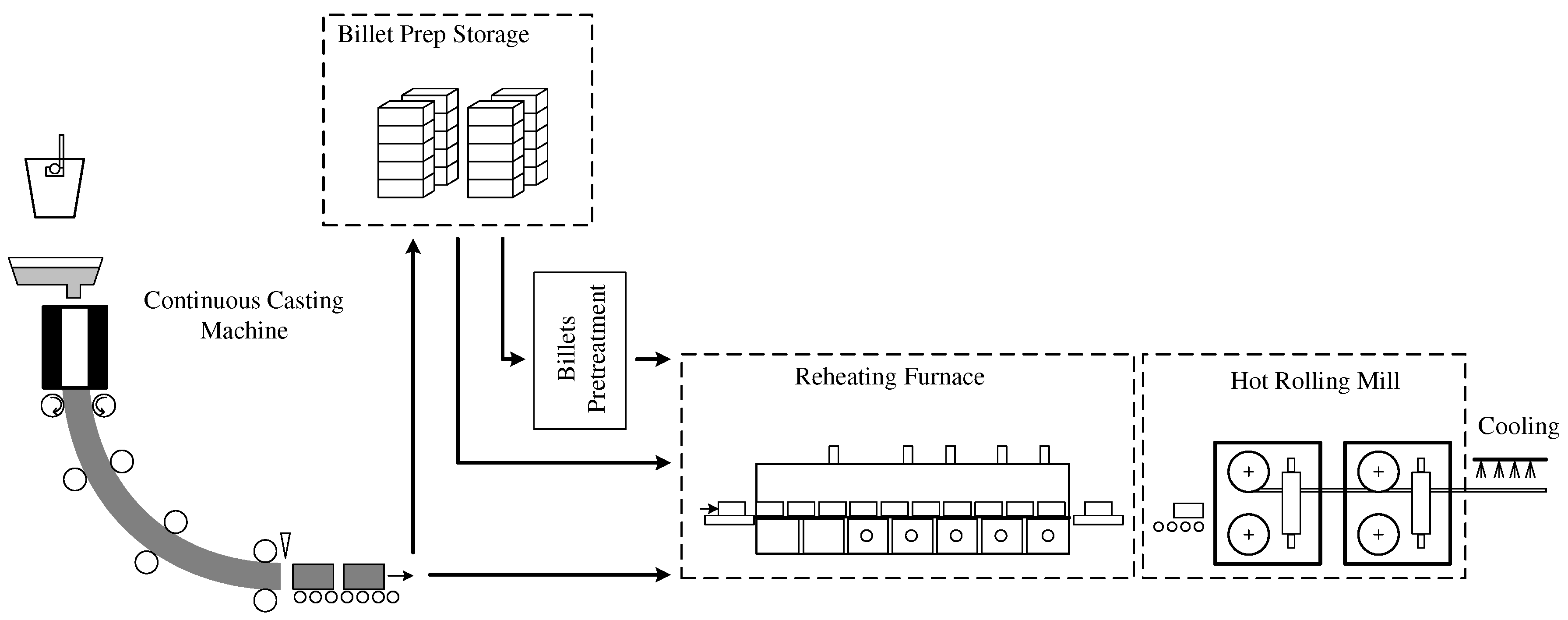
Figure 1 presents the production diagram.
CCM-cast blanks go to the warehouse. Some of them, if possible, go to the heat-treatment furnace to equalize the temperatures within the cross-section and to heat them to the level required for rolling. Storage is necessary to bring the CCM production rates in line with those of the rolling mill.
What complicates heating the blanks is the fact that a single furnace may simultaneously treat blanks of different initial thermal condition, different geometry, and different steel grades. Besides, the furnace performance is tied to that of the rolling mill. Heat-treatment furnaces are naturally continuously-running units that feature significant thermal inertia. A rolling mill is a discrete unit that rolls blanks one by one. Past a certain number of blanks, the mill needs to be stopped for maintenance. While under maintenance, it cannot roll, but the furnace is running. All of this complicates controlling the thermal condition of the furnace and optimizing the energy use of the pre-rolling heat treatment process.
The industry-average fuel consumption of the conventional metal heating process is 1.6 GJ/t [
1], or 18% of the total specific energy costs of rolling steel. The figure could be lowered by altering the rolling technology, improving the furnace design, and optimizing the production planning [
2,
3,
4] or the heat-treatment furnace parameters [
5].
A heat-treatment furnace is a thermal unit that transports blanks from the loading tray through its chamber to the unloading tray, from where the blanks go to the receiving roller table of the mill. The chamber burns fuel fed through rows of burners installed in the furnace vault and lateral walls under the passageway for blanks. Such placement of burners helps independently regulate the heating levels at different points in the furnace to adjust the furnace performance to that of the rolling mill. In turn, controlling the temperature distribution in the furnace helps attain the required heating curves to bring them in line with the chosen heating technology and the rolling stand production rates. The curves must minimize the energy costs of heating.
There are numerous papers on the problem. Thus, Tang [
6] presented a slab heating trajectory algorithm based on penalty functions, concluding that the furnace loads must be calculated in advance to reduce the energy costs of heating. Banadaki [
7] presented a neuro-fuzzy predictive heating model that calculates the required furnace zone-specific thermal loads.
The authors of [
8,
9,
10,
11] proposed mathematical loads to predict the thermal condition and optimize the operation of the heating furnace. The models vary in complexity as well as in the representation of the heat transfer processes. Wang [
12] proposed a dynamic adaptive fuzzy reasoning Petri net for machine state inferences to save energy considering the real-time production information.
The authors of [
4,
13,
14,
15,
16,
17] considered various approaches to dynamic optimization that can generate the blank heating trajectories to the specified criteria. Possible optimization criteria include fuel efficiency and heating quality. Some approaches use simplified mathematical models to generate blank-specific heating trajectories in real time.
When controlling a heating furnace, the main problem is choosing a blank heating trajectory that will minimize the total energy costs of heating the slab to a level required for further rolling.
What complicates the problem is that a furnace may simultaneously process blanks of varying initial thermal condition as well as of different steel grades. Rolling mills tend to have uneven, difficult-to-predict production rates, a fact that cannot be ignored. An additional thermal test of a blank before it exits the furnace helps prevent rolling mill accidents and stops by preventing insufficiently hot blanks from leaving the furnace.
In the mentioned papers, the operation of one particular control system is usually discussed with the stable operation of a rolling mill and without taking into account the operation of other subsystems for controlling parameters of a heating furnace or a current state of the rolling process. In this paper, the general structure of the optimal control system for heating billets before rolling is given. The presented control system shows the relationship of individual subsystems, each of which performs a strictly defined function. The joint work of these subsystems and their information interaction allows them to have common access to information about the technological process state. This allows creating optimal heating modes, taking into account all aspects that arise during the heating process.
2. Statement of Problem
The problem of optimizing the metal heating parameters is down to finding and implementing a heating trajectory at which the functional of heating costs or quality are minimum. Below are the principles of optimal heating control:
Analysis of the pass-through furnaces on an existing enterprise has identified the technological specifics of the pre-rolling heating process [
19]:
Compliance with the heating restrictions includes furnace lining and blank surface temperature constraints as well as constraints on the temperature variance within the cross-section of the heated blank to prevent the thermal stress from exceeding the ultimate stress of the blank material.
The furnace performance should be aligned with that of the rolling mill considering stops and emergency downtimes.
Research has identified the need for a complex optimized control system for heating continuous castings in pass-through furnaces.
3. Materials and Methods
Optimizing the metal heating in pass-through furnaces while minimizing the fuel consumption requires solving a variational problem. It is necessary to generate such control action that will change the thermal condition of the blank from its initial state to the required end state within given time while minimizing the functional of energy costs.
3.1. Theoretical Method for Optimal Control
The most appropriate functional is as follows:
where
T is the configured heating time, s.
is a value proportional to the fuel costs of heating-control temperature,
C.
The value of
is proportional to fuel consumption and, in a first approximation,
can be represented as
where
is the fuel consumption in the heating furnace, m
/h.
is the proportionality factor, h
C/m
.
The value of
is the value of the control action proportional to fuel consumption. Since the fuel consumption in a heating furnace has limits of change, the value of
also varies from
to
. The value of kp is determined experimentally for a heating furnace. The method for determining
is beyond the scope of this paper. Thus, Equation (
1) is an integral criterion expressing the amount of fuel spent on heating.
The system input is the control
proportional to the gas consumption; the output is the heating medium temperature approximated by the first-order inertial link with the time constant
. The differential equation that links the heating-medium temperature to the control action is as follows:
where
is the temperature of the heating medium,
C.
The mathematical description of the heating process of the billet in a heating furnace is represented as a one-dimensional heat equation:
where
is the temperature field;
is the time, s;
x is the spatial coordinate, m;
T is the specified time of the heating process, s;
is the heat capacity per unit volume, J/(m
K);
is the factor of thermal conductivity, W/(m·K); and
S is the assumed thickness of the workpiece, m.
Use the first variation of the functional for systems with distributed parameters and apply L.S. Pontryagin’s maximum method [
20,
21,
22] to write the necessary optimal condition for the stated problem as the functional:
where
,
,
, and
are conjugate variables found by partial differentiation of the functional in Equation (
4) with respect to the variables, to which the conjugates are calculated.
From the optimality condition in Equation (
4), derive the optimal control expression:
Integrating numerically the equation system derived from Equation (
4) by differentiating by conjugate variables means that finding a partial solution requires computing the functions of conjugate variables at zero time, i.e.,
and
.
The method for finding conjugate variables proceeds as follows.
1. Introduce an objective function to calculate the deviation of the computed end state of the system from the specified end state:
where
is the required distribution of temperatures within the blank cross-section,
C.
is the actual distribution of temperatures at the end of the heating time T,
C.
2. Reduce the problem by finding the initial values of the functions of conjugates
and
to a search problem, with reference to Equation (
8). Find such
and
that the criterion
J is minimum.
3. Find the minimum of the function in Equation (
8) by directly searching for the minimum of the function for multiple variables.
To calculate the actual blank temperature as it gets heated in the furnace given a pre-configured zonal temperature distribution, use the mathematical model based on a unidimensional thermal conductivity equation taking into account how the thermophysical properties of the material could be affected by the temperature [
23,
24,
25]. A fairly simple mathematical description enables the user to calculate the heating trajectory for each blank in real time.
3.2. Constraint Satisfaction
The heating process is subject to the process and design constraints of the heating unit. In that case, practical implementation of these calculations becomes difficult, as it is necessary to consider the actual design and process constraints that may exist on the site.
In that case, practical implementation of these calculations becomes difficult, as it is necessary to consider the actual design and process constraints that may exist on the site.
To solve the variational problem with constraints, such control action must be generated in the domain where the controlled process parameter faces its constraint such that it stays within it constraint. The constrained heating process parameters are the maximum temperature difference within the cross-section , the maximum heating-medium temperature , and the maximum blank surface temperature . Besides, it is also necessary to constrain the maximum magnitude of the control action .
To solve the variational problem with the constraints, use the developed algorithm and apply algorithms based on automatic control laws, including the PI control law, to keep the process parameters at their specified values [
26]. As input variable parameters, values are used on which constraints are imposed; as a value for setting the regulator, numerical values of constraints are used.
Automatic algorithms are configured to the requirement that the process parameter reach its maximum permissible value as fast as possible, with minimum subsequent deviations.
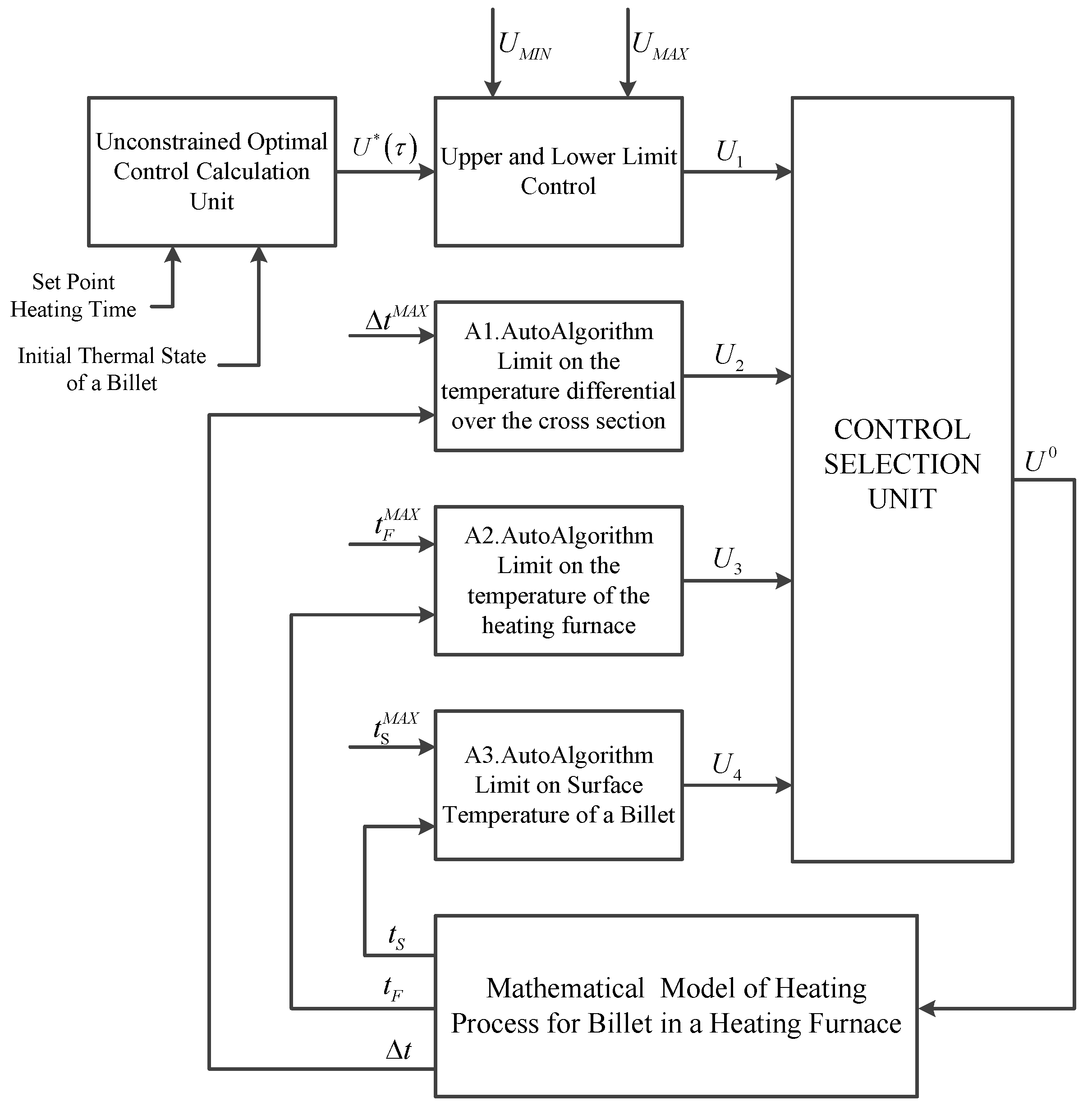
Figure 2 presents the diagram of generating an optimal-heating, minimum-fuel control trajectory accounting for the control action and heating constraints; the process uses automatic algorithms (AutoAlgorithms).
Figure 2 uses the following notations:
is the control action, non-constrained;
–
are algorithm-generated control actions fit to the constraints;
U is the control action chosen to the priority of the constraints in place; and
,
, and
are the heating-medium temperature, the blank surface temperature, and the cross-section temperature difference, respectively,
C.
The control selection block is to select one specific control action value to be in line with the priority of the constraints in place as well as with the optimal control strategy. The chosen control action is fed to the mathematical model of blank heating, which finds the temperature parameters of the heating process. The parameter values are fed to the respective algorithms. Repeat the cycle for each point of the control trajectory to find the full optimal control trajectory and to adjust the heating process parameters.
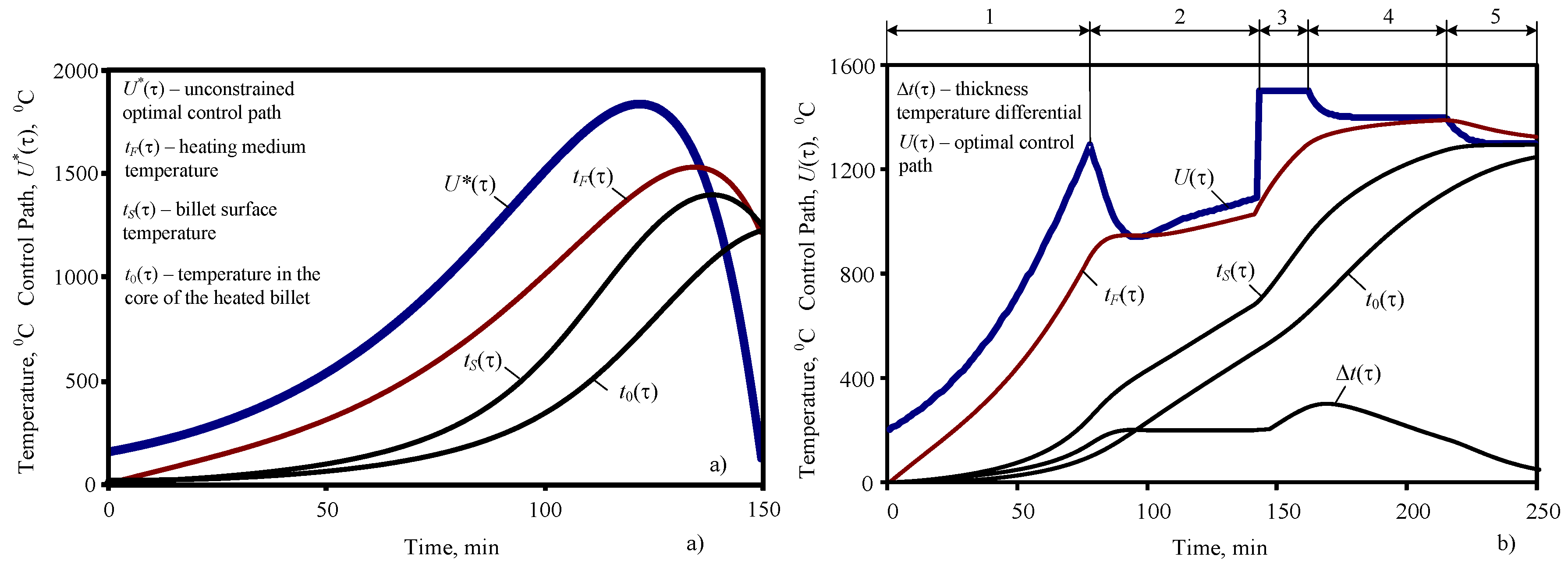
Figure 3 shows the optimal control trajectories with and without constraints.
Figure 3b uses the following notation: (1) no constraints; (2) maximum temperature difference within the cross-section constrained; (3) control action constrained; (4) heating-medium temperature constraints; and (5) surface temperature constrained.
The calculation produces the trajectories of heating-medium temperature and heated-blank surface temperature , the values of which can be fed to the local thermal condition control circuits placed in the zones of a pass-through heat-treatment furnace as the blank goes through it.
4. Implementation
What determines the effectiveness of heating optimization is whether it guarantees heating the blank as required before it exits the furnace. Given how uneven the rolling performance could be, optimized heating must not increase the risk of releasing an underheated blank that has been heated for a shorter time than assumed when calculating the optimal heating trajectory. Exceeding the assumed heating time is not acceptable either. In that case, although the heating quality might meet the requirements, heating could well be inefficient as more gas would have to be consumed to maintain the attained thermal condition.
It is also necessary to account for the redundant power of the heat-treatment furnace. At higher rolling performance, specific heating costs become lower. At peak rolling performance, the furnace also attains its peak performance, in which case further optimization by zonal heating control becomes impossible. This means pre-rolling heating efficiency can only be improved if the furnace performance is below its maximum.
The core subsystems directly involved with the control optimization are:
the instrumentation subsystem that monitors the blank movement in the furnace(s), and predicts and adjusts the blank heating time;
the subsystem that monitors the thermal condition of blanks when they enter and exit the furnace;
the subsystem that configures the zonal controllers to optimize heating and adjust the heating values depending on actual thermal condition of blanks leaving the furnace; and
the fuel combustion control subsystem.
Coordination of these core subsystems enables efficient energy-saving control over blank heating and prevents underheated blanks from leaving the furnace while also stabilizing the transients in transient states.
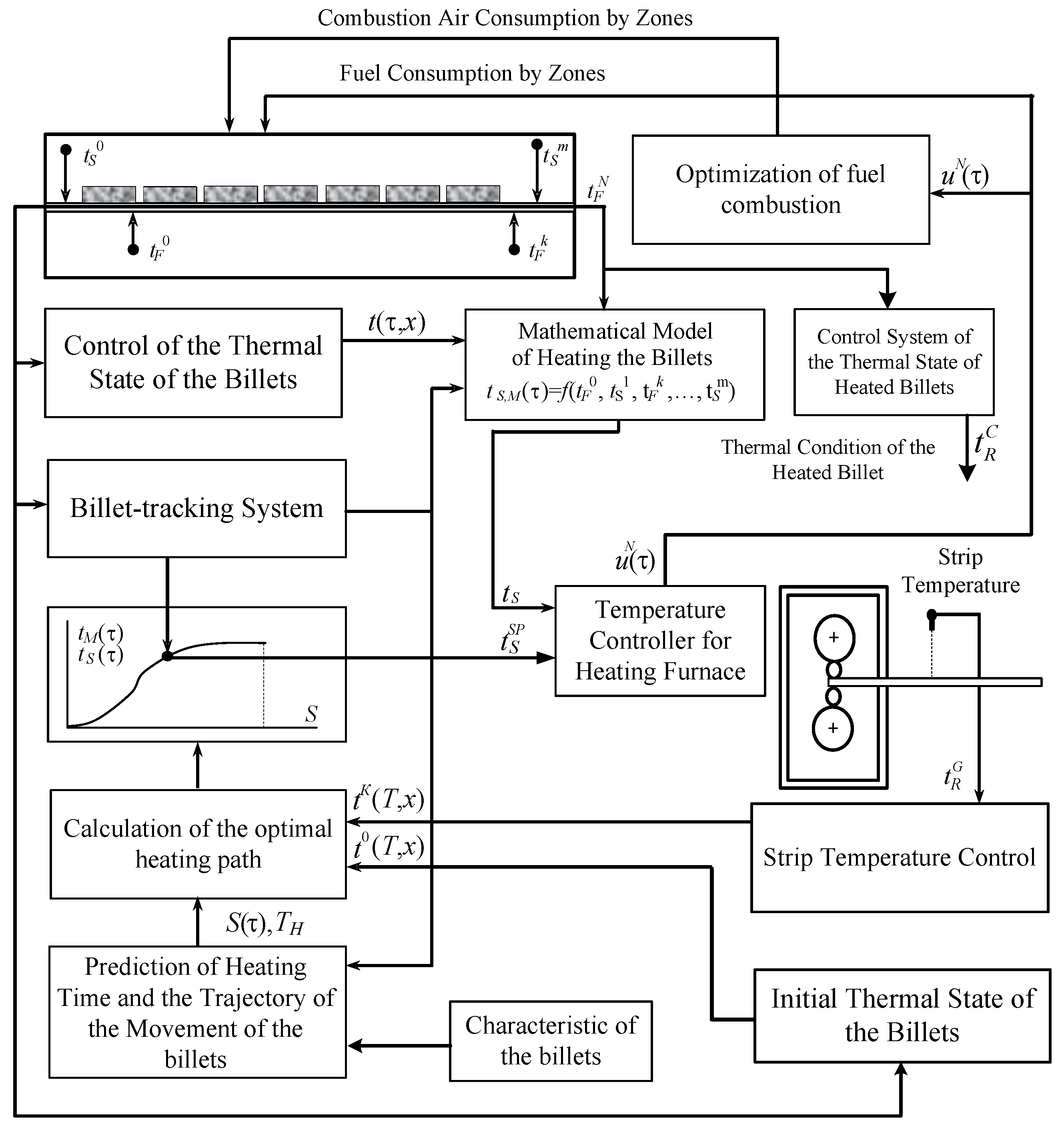
Figure 4 shows the structural diagram of the optimal energy-saving heating control system for a pass-through heat-treatment furnace. For each slab loaded in the furnace, calculate the optimal heating trajectory on the basis of the predicted heating time and initial thermal condition to minimize the energy costs of heating while also complying with all heating constraints; the trajectory is to be used by the furnace as the blank passes through. An additional stand-alone pre-exit heating quality control system will help prevent underheated blanks from leaving the furnace for a better rolling quality.
The blank monitoring system counts the steps taken by the walking beams once the blank is in the furnace; thus, it tracks the position of each blank in the furnace [
27]. The heating modeling algorithm uses the current blank coordinates and the zonal temperature sensor readings to calculate the thermal condition of each blank in the furnace. The energy-saving heating trajectory optimization algorithm is coordinated with the heating time prediction algorithm as well as with the initial state algorithm to calculate the metal surface temperature trajectory that will match the energy-saving heating curve; thus, it calculates the required blank surface temperature specific to its current position in the furnace.
This value is fed to the surface temperature controller operating at a specific point in the furnace. The actual surface temperature is a calculated value, either found by the blank heating model or measured by the surface temperature sensor. The surface temperature controller sends a control signal that adjusts the zone-specific gas flow. The fuel combustion optimization system optimizes the zonal air flow as a function of the actual gas flow. The upon-exit thermal condition monitoring system provides secondary objective heating quality control to prevent underheated blanks from entering the rolling mill. The rolling temperature stabilization system corrects the configured final thermal condition of the metal as it exits the running furnace so as to ensure the required value of the temperature of blanks leaving different furnaces.
One particular feature of this algorithm is that the thermal condition of a blank can be controlled with reference to the surface temperature, whether calculated mathematically or read by the surface temperature sensors. This does not affect the algorithm structures; sensorless furnaces can be gradually upgraded with sensors without altering the algorithm, which simplifies configuring the system.
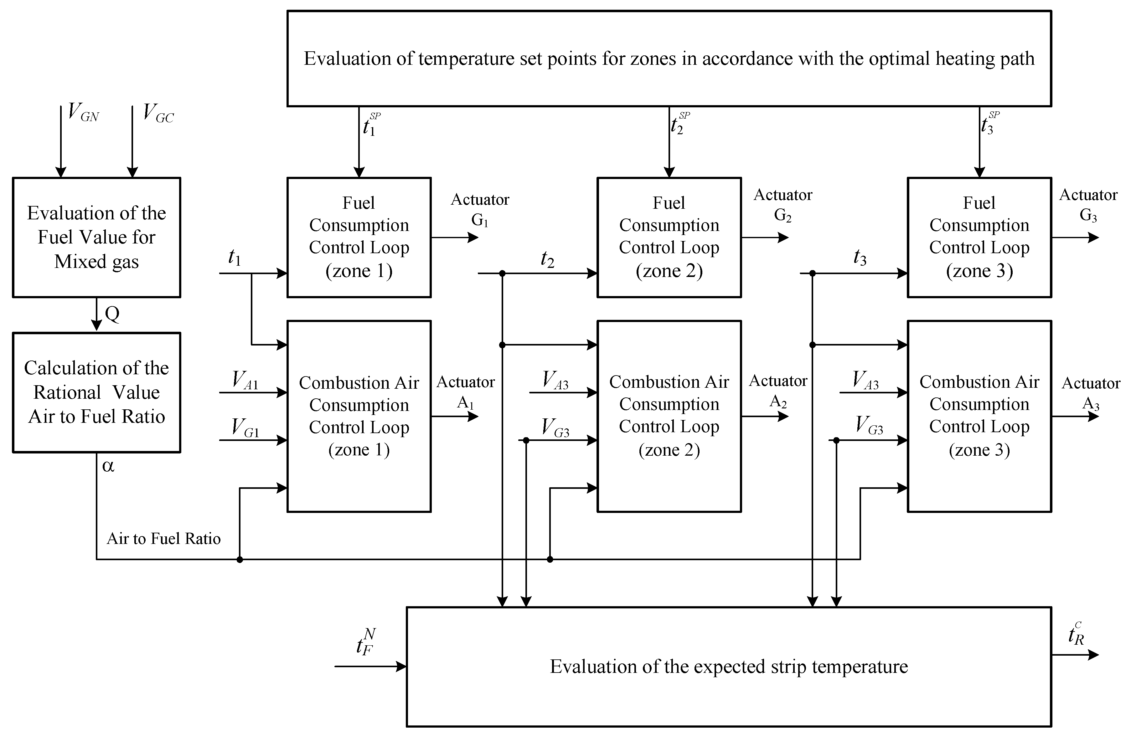
The system has been implemented at Mill 2500, a hot-rolling mill of ”Magnitogorsk Iron and Steel Works Inc”, (Magnitogorsk, Chelyabinsk, Russia). The mill has six push-type heat-treatment furnaces, each featuring five controllable heating zones and firing a mixture of coke and natural gas. The core heating zones are Zones 1–3. The optimal control system has only been implemented for the core heating zones. Zones 4 and 5 are intended to level the temperature cross-section-wise; they have low heat output and are always fueled at max, which is why they are not involved in heating controls.
Figure 5 shows the zone control system structure.
5. Result
The optimal control system configures zone-specific temperatures to optimize the blank heating path. Measured coke and natural gas flow rates are used to optimize the gas-mixture combustion factor and adjust the zone-specific air flow accordingly. The upon-exit thermal condition monitoring system prevents underheated blanks from going to the rolling mill.
When assessing the performance of the system, a period of time was selected at which the productivity of the rolling mill did not change. The productivity of heating furnaces at this time remained constant and equals 140–145 t/h. During this time, the operation of the furnace was transferred to control from the existing system to the optimal control system and returned back. This was done so that all external factors affecting fuel consumption remain unchanged and do not affect the estimate of the amount of change in fuel consumption for heating under different control modes.
Figure 6 presents the gas flow curves for Zones 1–3 with the optimal thermal load control system on and off.
Where the optimal control system is off, the zonal temperatures are set per the process map.
Table 1 shows the changes of gas-flow rates in Zones 1–3 and compares the optimized thermal loads vs. process-map thermal loads.
Table 1 shows the final indicators obtained as a result of averaging the results of several experiments when switching to control the thermal regime from the proposed system with the same productivity of a heating furnace (140–145 t/h).
Experiments have shown that using the optimal control system reduces the fuel consumption by 8.46% given there is enough time to heat the blanks. Whether the system is going to be efficient depends on the furnace runtime, during which redundant power is available. This accounts for 30–45% of the total furnace runtime. The rest of the time, heat-treatment furnaces are running at peak performance and maximum zonal thermal loads. YoY reduction in fuel consumption is 2.54–3.81% per furnace, or 1311 to 1505 thousand m of natural gas per annum.
6. Conclusions
The optimal heating control system is efficient provided that the furnaces have redundant power and are capable of zonal distribution of thermal loads. For a typical hot-rolling mill, redundant power is available for 30–45% of the total runtime; the rest of the time, furnaces run at peak performance and minimum specific fuel costs. Furnace control optimization requires solving a number of interrelated problems using separate subsystems. The implemented optimal control system saves 2.54–3.81% of fuel for heating, which equates to 1311–1505 thousand m of natural gas per annum for Mill 2500 at Magnitogorsk Iron and Steel Works Inc, (Magnitogorsk, Chelyabinsk, Russia).
Moving forward a comprehensive investigation of the process of optimal heating path generation is planned to be conducted. To this end, a mathematical model of the operation of a heating furnace will be created, in which the emphasis will be placed on modeling relationships between individual processes and control systems for these processes. Using a mathematical model, simulations will be made of the supply, movement and heating of a billet in the working space of a heating furnace under different operating conditions. This will clarify the proposed method for an optimal heating path generation, taking into account the influence of the initial thermal state of a billet, mill capacity, thermophysical characteristics of a heated billet, and the interaction of individual subsystems.


