1. Introduction
A bicycle transmission is the set of all those elements that participate in the transfer of power from the pedals, given by the cyclist, to the rear wheel. The most popular system consists of two pedals connected to a crankset that put in rotation one or more chainrings connected to one or more sprockets through a chain. The set of sprockets is called cassette and the task of shifting the chain through different sprockets is assigned to the rear derailleur. The history of bicycle derailleur is widely and deeply analyzed in the literature [
1,
2] and can be summarized here by main achievements. Variable gears for bicycles appeared in some patents between 1868 and 1869 [
3,
4]. Then, a variety of pre-derailleur and epicyclic systems were developed between 1900 and 1907 [
1]. Early rear derailleurs appeared at the beginning of 1900, but the four systems conceived in 1908 by Perrot, Prevel d’Arley, Tri-Direct and Boizot [
1] are considered the starting point of the modern derailleur design that evolved in different versions up to the current market, eventually including electronic control.
The modern rear derailleur is placed under the cassette and consists of two jockey wheels connected to a rotating and translating arm that has the double role of shifter and chain tensioner. The translation is possible thanks to a mechanical parallelogram that was first introduced by Nivex in 1938 [
1]. The parallelogram is actuated by cable or through a servomotor in recent high-end market versions. In both cases, the control is provided by the rider through levers or buttons on the handlebar. The cassette is integral to the wheel and has a partial degree of freedom with respect to the wheel. The free-wheel (or free-hub in older products) is a one directional bearing that allows the relative rotation only in opposite direction with respect to the travelling verse, preventing the moving bicycle from turning the pedals but letting the torque be transmitted when the rider is pedaling.
Alternative systems have been introduced over the years including epicyclic gearing inside the hub [
5,
6,
7,
8], expanding chainrings [
9], belt/cable and pierce shaft drive systems [
1,
10], oscillating drives [
11] and continuously variable transmissions (CVT) [
8,
12,
13,
14]. Some of these alternative solutions have found a position in non-racing market segments such as city and touring bicycles due to lower maintenance requirements and cleaner interaction with the cyclist’s clothes. In particular, interesting CVT solutions were developed in many transportation systems. Due to their compactness and lower maintenance [
15,
16], they have a good potential in application to daily commuting bicycles and green vehicles. However, they never entered the racing market due to the lower and not constant efficiency and/or weight issues [
17]. Other studies were developed around automatic shift [
13,
18,
19,
20,
21] often with particular focus on e-bikes.
The conception of innovative solutions on strongly consolidated market products is often hampered by constraints that prevent the designer from imagining alternatives to the existing one. These constraints can be dictated by the presence of standard components with which the product must interface or simply by the persistence of a certain design solution over years, that influences the vision of the designer [
22,
23,
24]. One area where this situation often occurs is the design of road bicycles for sports use and their components, such as the gear shifter. The rules dictated by the UCI (Unione Cycliste Internationale), combined with the difficulty in introducing new products that require the modification of existing standards, are sometimes very influential project constraints. Often in these situations it may be useful or at least interesting to break away from standards and preconceptions, exploring solutions that are not trivial even if apparently not applicable to the specific context [
25]. Moreover, it has been highlighted by Piancastelli et al. that an innovative approach to the development of an optimized solution requires being trans-disciplinary [
26]. Therefore, it happens that innovation may come from complex paths, for instance through a niche market such as recumbent bicycles or even more extreme projects that have only the pedals and wheels in common with the road bicycle. This is the case of human powered vehicles for high-speed competitions, such as those racing every September at the WHPSC (World Human Powered Speed Challenge) in northern Nevada (US) on a flat straight of 8 km to reach highway speeds (world record 144.17 km/h, Todd Reichert 2016). More details on the boundary conditions that drive this unique race are already presented in the literature [
27,
28,
29,
30] and are discussed below in relation to the project requirements.
In this context, the project of a gear shift with a moving cassette instead of derailleur was born, which led to the filing of two patent applications. Starting from these, a third solution is currently under development for implementation on traditional bicycles. The conception, design and testing of the first two versions are presented in this article by discussing their design requirements and the project evolution. Then, an overview of the new development towards standard bicycle is presented with a focus on issues and non-technical aspects to consider when proposing such a product on a well consolidated market.
2. Project Constraints and Requirements
To express maximum muscular power, the pedaling movement must be performed within a specific cadence range, which depends on subjective factors as well as on the crank length. According to Abbiss et al. [
31], with standard 170 mm cranks, the optimal cadence for an average sized male athlete settles around 100–120 rpm to maximize power and slightly below (90–100 rpm) to maximize efficiency. This is essentially related to the behavior of the muscle fibers (for details, see [
32]).
It follows the need for a variable transmission ratio that allows the cyclist to work in the desired cadence range while varying the vehicle speed. The latter is a function depending on the power input from the rider, the characteristics of the rider-vehicle system (weight, reference area, drag and rolling resistance coefficients, and transmission efficiency) and the boundary conditions (road slope, air density, wind intensity and direction, and acceleration). As summarized by Wilson [
10], all these factors and the vehicle speed are related as:
where
is the power input from the rider (rate of mechanical work delivery),
is the air density,
is the drag coefficient,
A is the reference area,
V is the speed relative to the ground,
is the wind speed in travelling direction,
m is the overall mass,
g is the gravity acceleration constant,
s is the road slope (sine of angle),
is the rolling resistance coefficient,
is the “effective” mass including the rotational inertia of the wheels,
is the instantaneous acceleration of the system and
is the transmission efficiency from the pedals to the wheel. The reference area is typically the frontal projection for unfaired cyclists (where the pressure drag is dominant) and the wet surface for streamlined object such as faired HPVs (where the shear drag is dominant).
A consolidated reference for the bicycle transmission ratio is the metric development, which is the distance travelled with an entire revolution of the pedals. Typical values are 4–5 m for a single-speed city bike and cover a range from 2 m to about 10 m for a road racing bike. To reach the extreme speeds of the WHPSC, metric developments up to over 20 m are required. Limiting the number of gears to a reasonable amount of 11–13 (according to the currently available cassettes on the market), a compromise is needed on the starting metric development. Usually, a starting value around 7 m is acceptable, considering that the competition rules allow for an external hand-push in the first 15 m, while a metric development of 8 m can be critical.
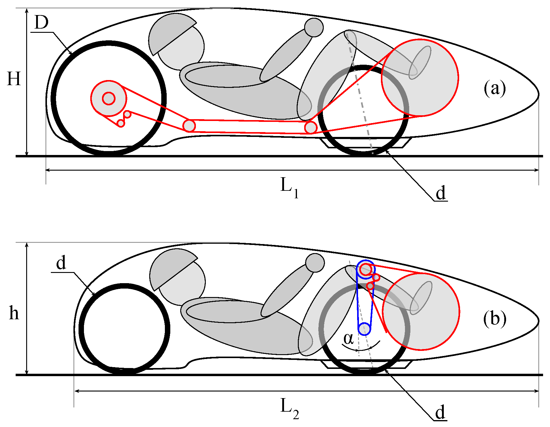
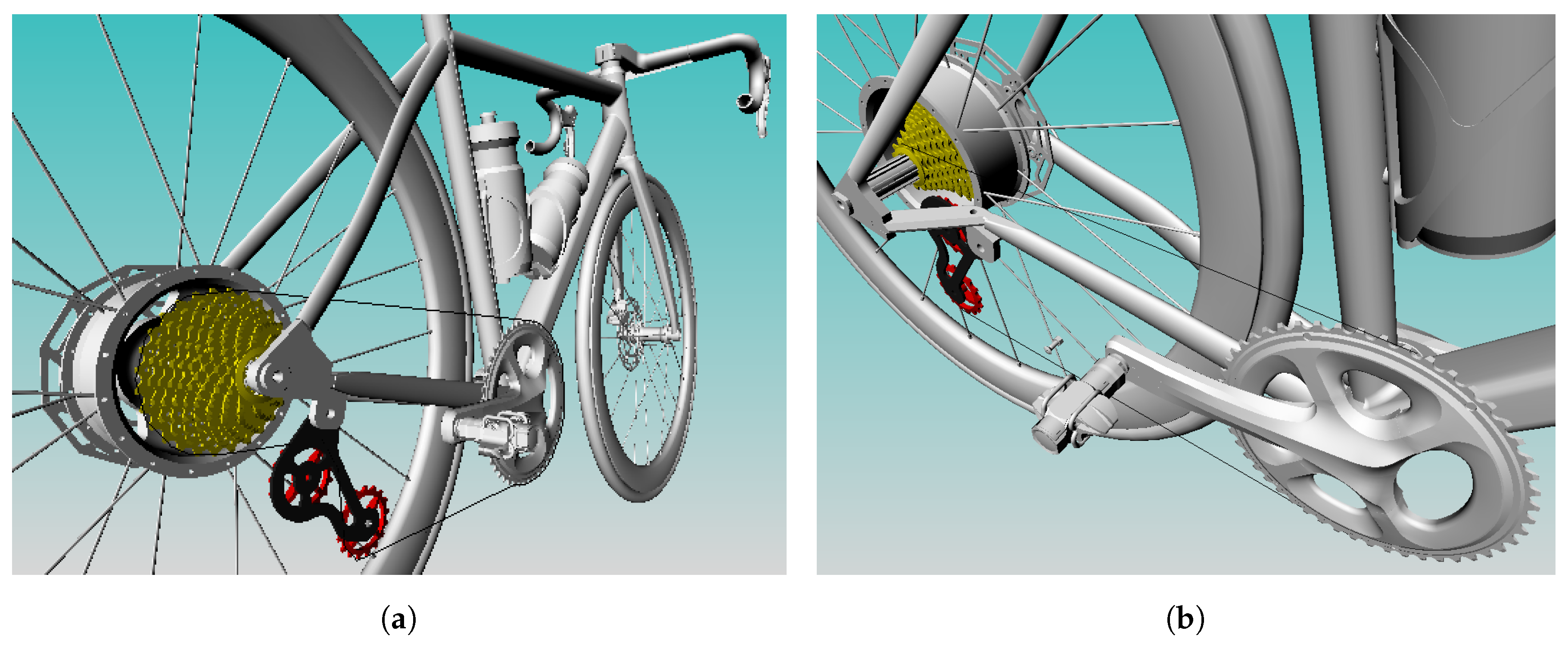
The supine position of the rider in high-speed HPVs imposes additional design constraints. The first critical choice concerns the transmission layout, for which two configurations are the most common:
Rear Wheel Drive (RWD) using a long transmission chain, often requiring a couple of pulleys (single or double-stage depending on the rear wheel size) to pass under the seat, as in
Figure 1a; and
Front Wheel Drive (FWD) using a two-stage transmission, as in
Figure 1b, for two main reasons:
- -
to reach the maximum metric development through an intermediate multiplication since the front wheel is often small; and
- -
to reduce the angle between the axle of the fork and the chain traction force on the wheel, so as to minimize the steering effect of pedaling.
The main advantages of the RWD solution are to allow a larger traction wheel and to require only one chain tensioner, an element that significantly contributes to efficiency losses. However, the price to pay is a higher vehicle with consequent drawback on the frontal area and thus higher aerodynamic resistance. Moreover, if a larger wheel is used at the rear, the vehicle may be longer, affecting the wet surface, which is another important aerodynamic parameter for these kind of shapes.
Currently, all the fastest competitor designs (including the world record holder) are converging towards FWD. With this solution, two main issues challenge the designer:
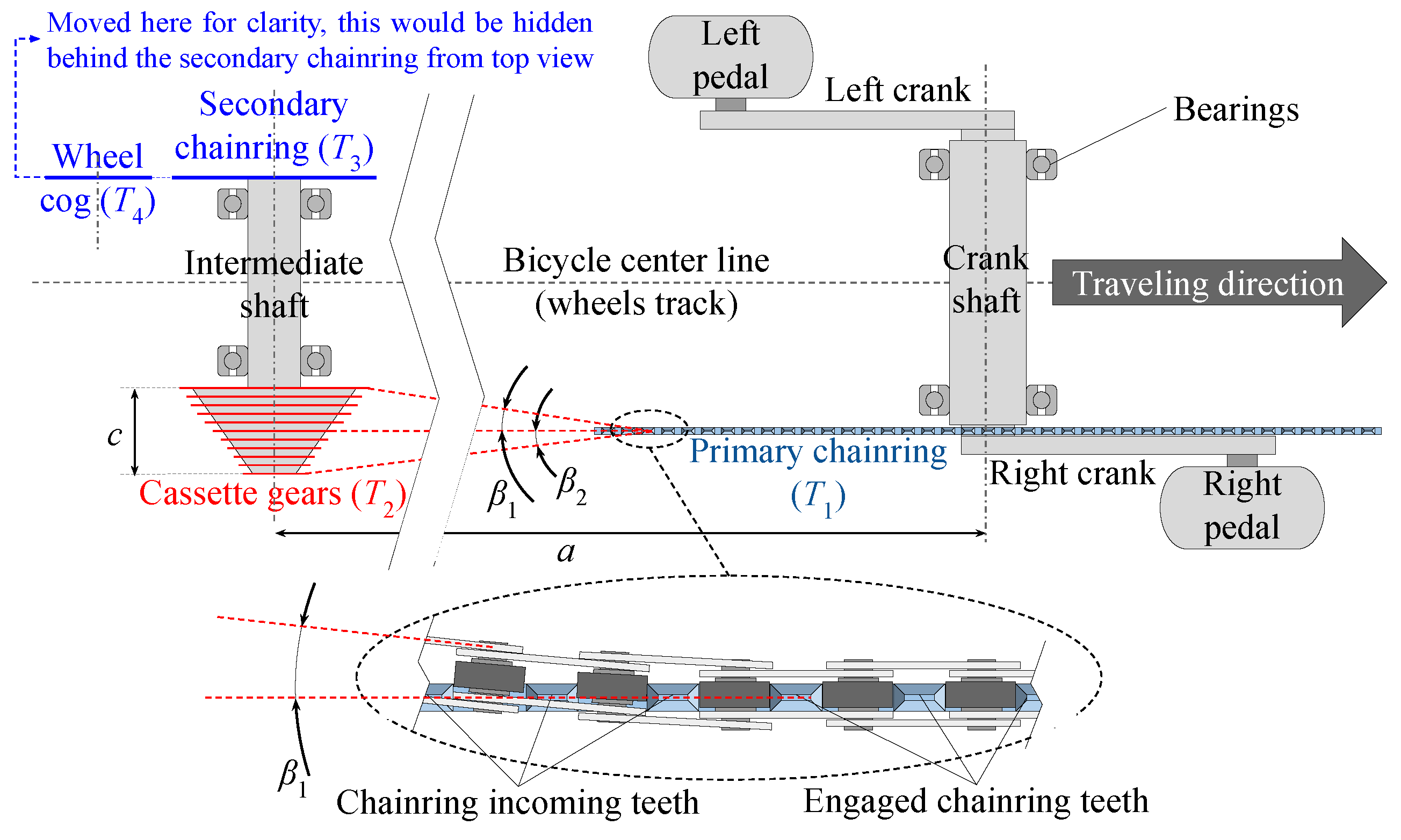
The chain misalignment brings, in general, three issues: slightly reduced efficiency (2–3 Watts according to CeramicSpeed [
33]), higher wear rate (on chain, chainring and cogs) and a higher probability for the chain to drop off the front chainring, growing with the offset angles
and
with reference to
Figure 2. The last issue is also present in traditional bicycles, in particular with the most recent trends in shortening of the wheelbase and toward the use of single front chainring. Even small offset angles can drop the chain off the chainring under dynamic loads coming from the road and different solutions have been introduced on the market to limit this phenomenon, such as chain-keepers and alternated narrow-wide teeth thickness.
To deal with these issues, most WHPSC competitors with FWD designs were using a reduced number of gears (5–7) until 2016, with a significant drop in pedaling cadence after each gear shift and a consequent power loss. A previous solution using a moving cassette shifting system was often mentioned by the most veteran participants, but unfortunately no track of this design is currently available to new participants. Other moving cassette projects were found in the state of art [
34,
35], but all have been developed in a mechanically actuated version by cable.
In this framework and within these design requirements and constraints, a solution for electromechanical actuation of a moving cassette shifter was developed and is presented in the following sections.
3. Design and Construction
The first step in designing the transmission was to evaluate the metric development range needed for the WHPSC purposes. The designated bicycle had a FWD transmission with a double-stage setup, as in
Figure 1b. The selected tire had a E.T.R.T.O. 28-406 [
36], which inflated to the nominal pressure of 8 bar and, subjected to the total load (90 kg), has an effective rolling radius of 233 mm. Starting from these data, a spreadsheet was created to evaluate the metric development and to select the most suitable cassette and left side sprockets. The relation between vehicle speed
V and pedaling cadence for a given chainring/pinion combination on the two stages can be calculated as:
where
represents the number of teeth of each involved chainring/pinion in sequential order from the pedals toward the wheel (
Figure 2) and
M the metric development which is then expressed as function of the effective rolling radius
(accounting for the loaded tire compression) and the pedaling cadence
expressed in rad/s. The obtained speed
V is in m/s. The spreadsheet was built as reported in
Table 1 by considering a decreasing sequence of
as needed to achieve a speed ramp from standing start to the highest desired speed. In the table,
is expressed in rpm and
V in km/h as they are more practical units in the specific context.
For each value of
, the desired maximum cadence is imposed as an input (
) and the corresponding speed
is calculated. Then, by inverting Equation (
2), the
for the next value of
is calculated at a velocity
, which corresponds to the previous
(speed continuity over the ramp), with the exception of the starting cadence obviously set to zero. Once the spreadsheet was available, the best
values were defined according to the following constraints and desiderata:
Reuse the 108 teeth chainring () available from the previous project.
Avoid for higher efficiency (less chain link relative rotation) and, in general, prefer bigger pinions.
Comply with bicycle market cassette and pinions to avoid custom production (also for ).
Avoid cadence drop below 95 rpm and increase the cadence at highest speeds, when the maximum power is required from the rider.
Set a starting metric development from 7.0 to 7.5 m.
3.1. First Design (2017)
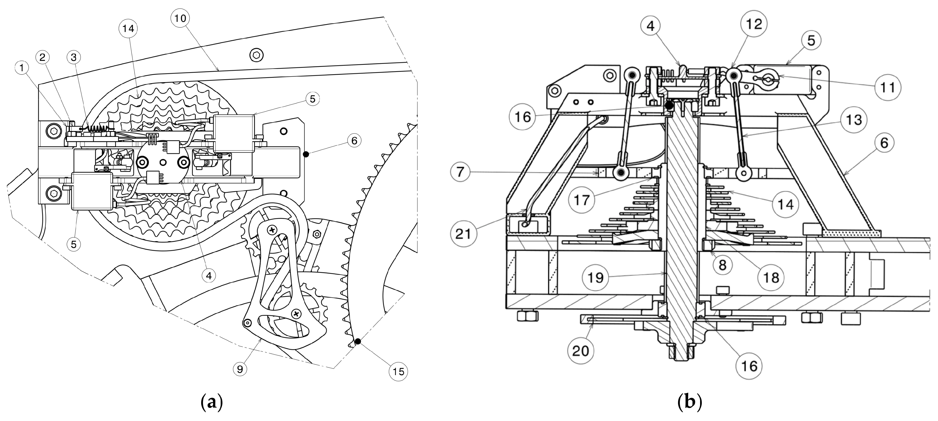
With reference to
Figure 3, the first design of the system developed in 2017 controls the translation of a grooved sleeve (18) on a lubricated splined transmission shaft (19), which is free to rotate thanks to the support bearings (16) and transmits the rotary motion from the left side of the transmission to the right stage chainring (20). Here, a secondary chainring in connected to the pinion at the wheel. The cassette (14) is housed on a grooved sleeve (18) and fixed by a ring nut (8). A chain tensioner (9) is laterally fixed in perfect alignment with the chainring (15) and it allows the exceeding chain (10) to be recovered when working on smaller pinions. The actuation takes place by means of two servomotors (5) mounted on a support (6) and managed through a printed circuit board (4) and an Arduino micro-controller. Each servomotor arm (11) acts, through a rod (13) with spherical joints (12), on the control plate (7), which is mounted on the grooved sleeve (18) by means of a bearing (17). The control plate (7) has an H shape to be able to overlap on the profiles of the portal support (6) and transfer any torque created by the bearing (17) on the structure itself and not on the lever system, increasing the useful life of the handling elements. A feedback loop control by means of an optical sensor (1) was included to read the position of the control plate with respect to an encoder film (2) kept in tension through a spring (3).
When the cyclist presses one of the two buttons on the handlebar, the micro-controller checks that the shifter has not already reached the extreme position in the requested direction and, if not, it sends a signal to the Printed Circuit Board (PCB) (4), which operates the servomotors (5) of the angle necessary to reach the previous or next pinion. This rotation produces a thrust or traction on the control rods (13) and then on the control plate (7), causing the translation of the grooved sleeve (18) and of the pinion cassette (14) constrained thereto. Each gearing position is memorized by the micro-controller in a calibration phase. The stored positions can be calibrated if necessary by accessing a specific sub-routine procedure of the control software.
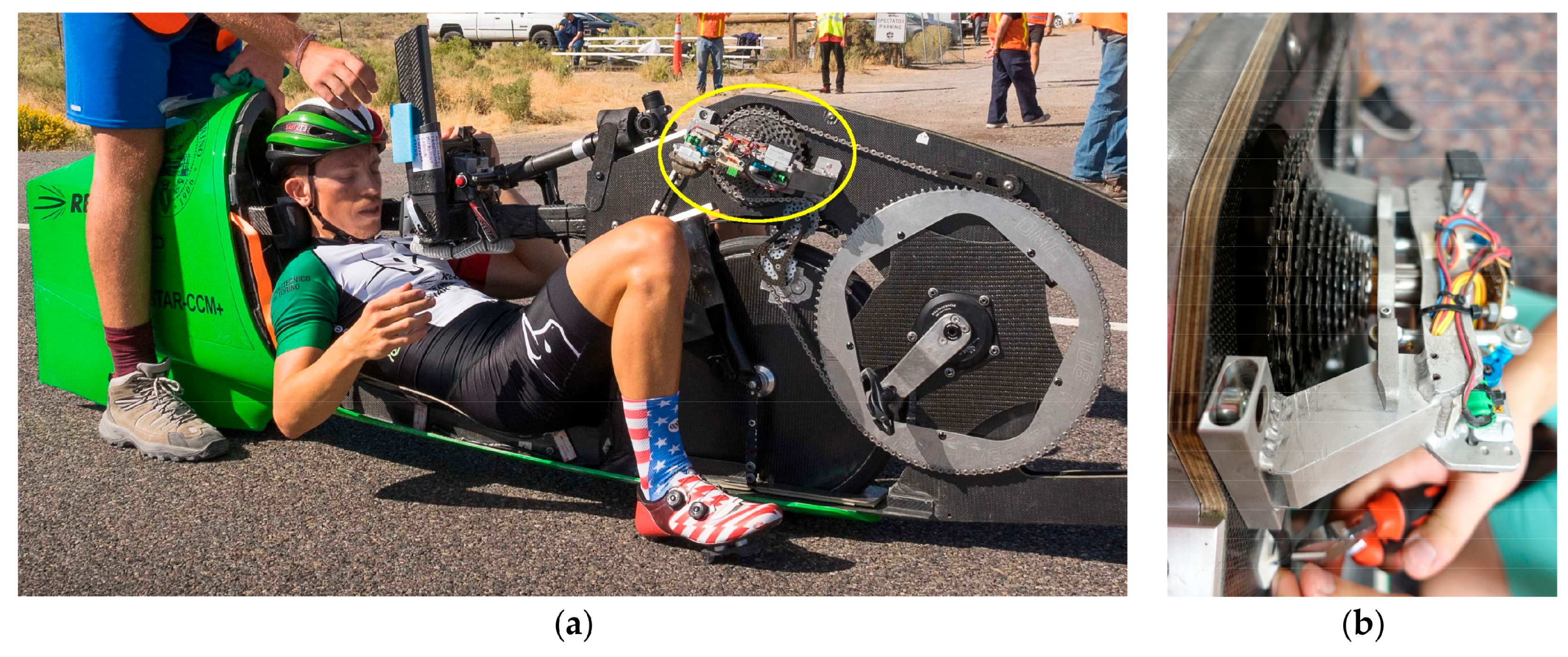
This first design was manufactured, assembled and tested in 2017 on the streamlined HPV of the team, as shown in
Figure 4. After solving some minor issues on the mechanical assembly of the control plate and bearing, the system was tested on the road showing acceptable reliability and precision. In this first prototype, the supporting portal (6) was manufactured in 6061-T6 aluminium alloy as the control plate (7). The shaft (19) was machined from a C45/1.1191 commercial grooved profile that is sold in combination with a bronze sleeve (18). The selection of the servomotors was made by considering the friction coefficient between these reciprocal sliding parts in highest torque conditions. In particular, assuming a pedal force
N on one pedal (60 kg rider in recumbent position), combined with a crankset length
mm as adopted in this HPV project and a starting gear ratio of 108/40 teeth on the right side (
mm and
mm radius, respectively), the resulting torque on the cassette/sleeve/shaft system can be calculated:
This torque is transmitted from the splined sleeve to the shaft at an average radius of 11.5 mm resulting in a total contact force of 2980 N. Considering a friction coefficient of 0.05 in lubricated conditions for the bronze on steel, the servomotors must be able to push 145 N overall. As a consequence, two SAVOX SA-1283 (JSP Group International BVBA, Olen, Belgium) were selected, which are able to provide a maximum force of 180 N when the connecting linkage is at (+24% than the nominal need to account for overload from non-perfect lubrication, eventual dirt or debris, etc.).
A national patent application was filled right before the race in 2017 [
37] with the idea to further develop the project towards standard bicycle market.
The HPV with this shifter was used during the WHPSC 2017, where the team reached second place both in the collegiate category and in the overall male rider ranking. The design was appreciated by other competitors and the team from TU Delft adopted a derived shifting system in its next bike VeloX 8 for the WHPSC 2018 [
38]. However, during testing and competition, some issues emerged from the non-linearity of the actuation system, which required frequent calibration procedures. Furthermore, the optical encoder for reading the position turned out to be inadequate with the vibrations from the road due to its excessive resolution and sensitivity.
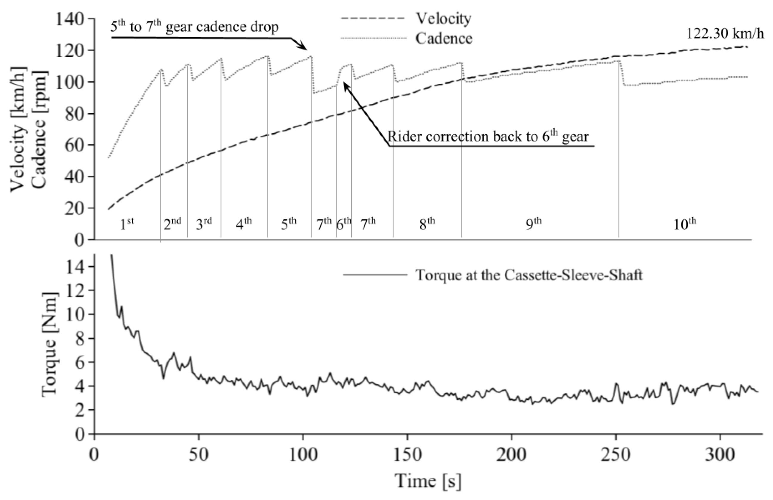
Both rider feedback and race data highlighted occasional shifting errors. An example is shown in
Figure 5, where the cadence drop gives evidence of a shift error skipping from gear No. 5 to No. 7 (the subsequent back-shift to No. 6 follows as correction from the rider). From the power and cadence data, it was possible to calculate the torque at the crankset and then at the cassette shaft by considering the engaged pinion. The first few seconds are missing due to a lag in the data recording start, but the initial torque peak is close to the value estimated in the design phase (12.4 Nm at the cassette). Actually, the value at the start could be much higher, but this is not considered a problem for two reasons: from 0 km/h to about 12 km/h the rider receive a push from outside (within the first 15 m according to the rules) so that the pedaling torque is less than what the initial trend would suggest; this peak value occurs in a phase where the shift is not actuated and the first shifting occurs when the torque is well below 8 Nm, which is far less than the design phase estimation.
As a consequence, in 2018, seizing the opportunity of a revision of the project for weight reduction, the team decided to develop a new design to overcome the previously mentioned issues, as described in the following section.
3.2. Second Design (2018)
The 2018 solution for the moving cassette shifter differs from the previous one due to the linearity of the actuation system. By comparing
Figure 3 and
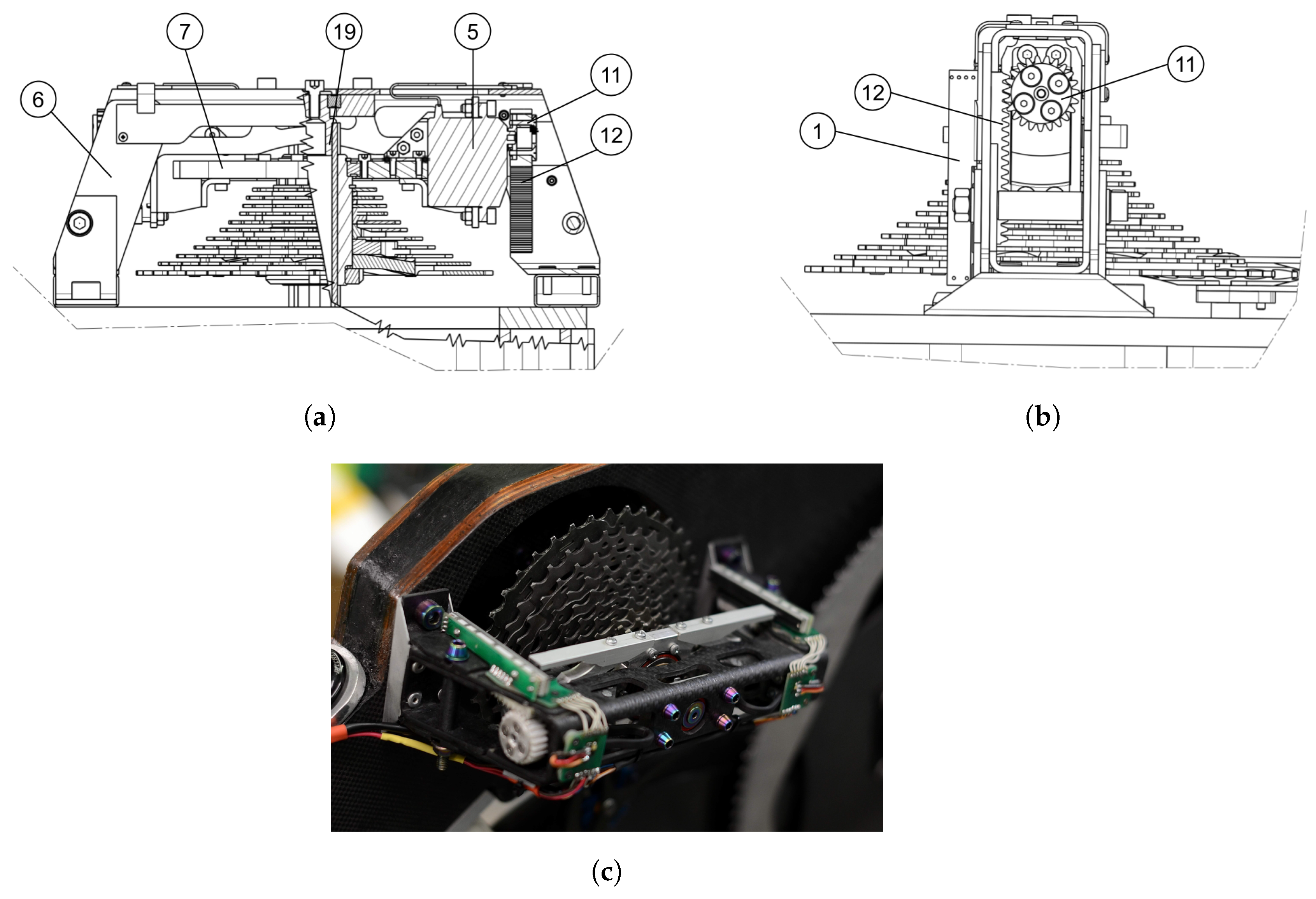
Figure 6, the differences can be noticed: instead of fixing the servomotors (5) on the portal support (6), they were positioned on the moving control plate (7) and so that the movement is actuated by means of a direct pinion-rack system (11,12). In this way, the project has been simplified by eliminating spherical joints and connecting rods that were sources of mechanical clearance. Moreover, the optical encoder has been replaced by two linear potentiometers (1) providing a more stable and reliable signal that is directly sent to the servomotors replacing their own position feedback internal loop, thus accounting for clearance and pinion-rack backlash. Finally, in the new design and construction (
Figure 6c), the support portal has been glued from CF-epoxy profiles and the splined shaft (19) has been hollowed, with a total saving of 1.1 kg.
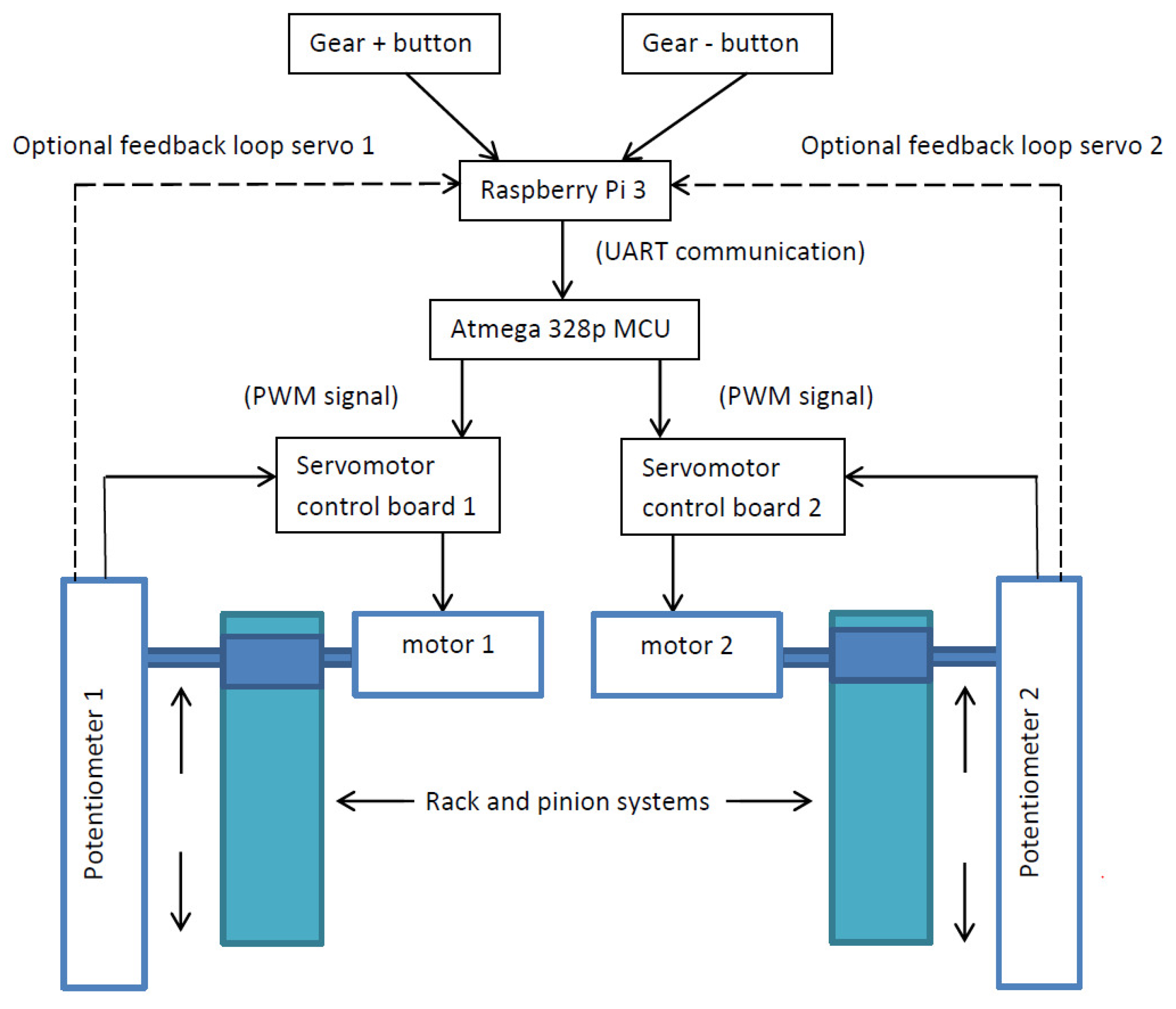
With the calibration function, each gear gets a specific value for each servomotor. These may be different due to electrical and mechanical inaccuracies. The value will range from the minimum and the maximum position of the rack and pinion system. The value is feed by the Raspberry Pi 3 to the micro-controller unit (MCU), which converts it to a suitable pulse-width modulation (PWM) signal that is passed to the controller of the servomotor. The servomotor board handles the feedback signal with an electronic comparator. No software is involved in this part of the system. An optional feedback line can be closed to the Raspberry Pi 3, but this signal serves a safety precaution. If the system is moved while the transmission is turned off, the controller will detect the variation of position and prevent the transmission from moving when turned on. The flow chart in
Figure 7 shows the layout and the logic of the involved electronics.
Due to the substantial difference in the actuation system, a new national patent was deposited [
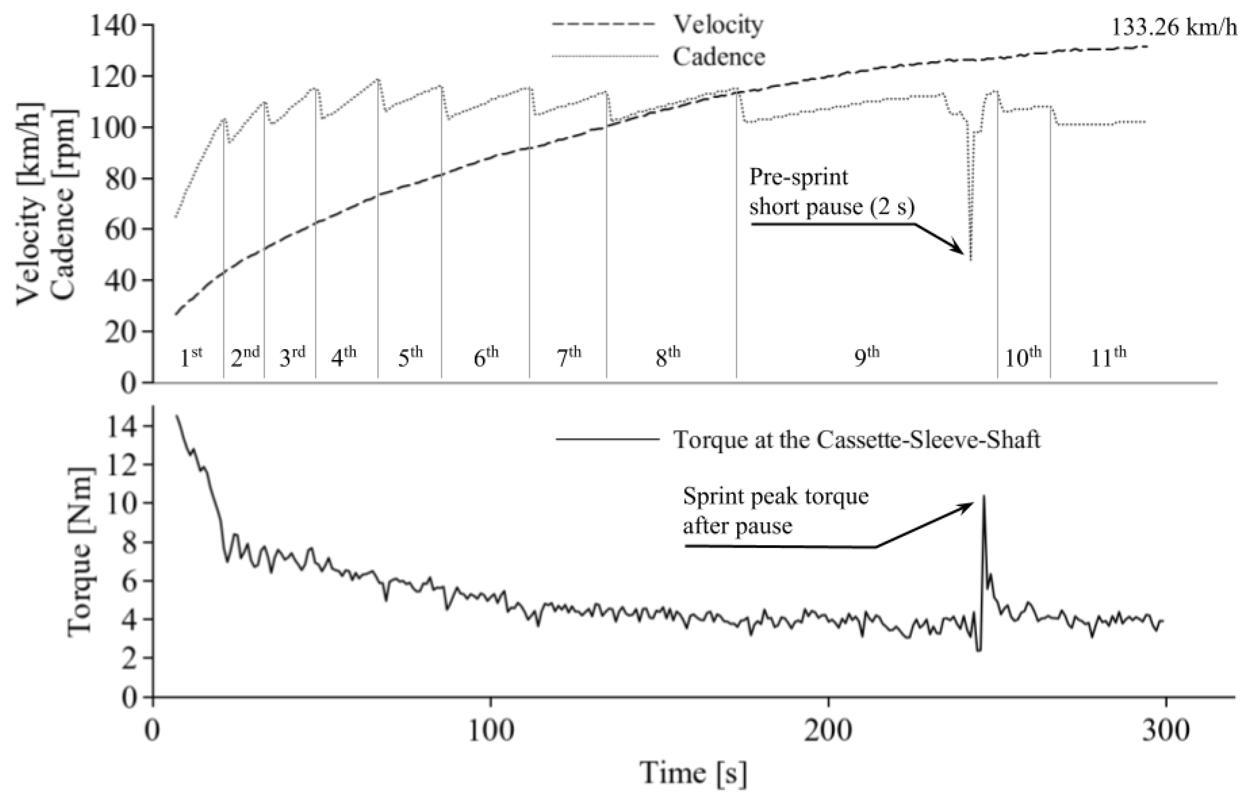
39]. The new system replaced the previous one on the same streamlined HPV and showed higher accuracy and reliability in both testing and competition. Combined with other improvements (mainly in rolling resistance), this updated system allowed the team to win the WHPSC 2018 both in collegiate and overall male rider ranking with a top speed of 133.26 km/h.
An example of run data from the 2018 edition is shown in
Figure 8. With respect to
Figure 5, no trace of shifting errors is present here and the only drop in cadence (in the ninth gear) is due to a voluntary choice of the rider to make a short pause of a couple of seconds before the final sprint, with the intent to allow a blood re-flow in the leg muscular fibers. Since the gear ratio was unchanged, the range and peak of cadence is similar between
Figure 5 and
Figure 8, but the new version shows perfect execution and absence of gear skipping, which allowed the rider to concentrate on his power output without the need to correct misbehavior from the shifter.
Again, the improvement was noticed by other competitors and the TU Delft team is currently implementing a moving cassette with rack-and-pinion linear actuation on its new bike VeloX 9 [
40] for the WHPSC 2019 that will be held next September.
4. Comparative Data Analysis
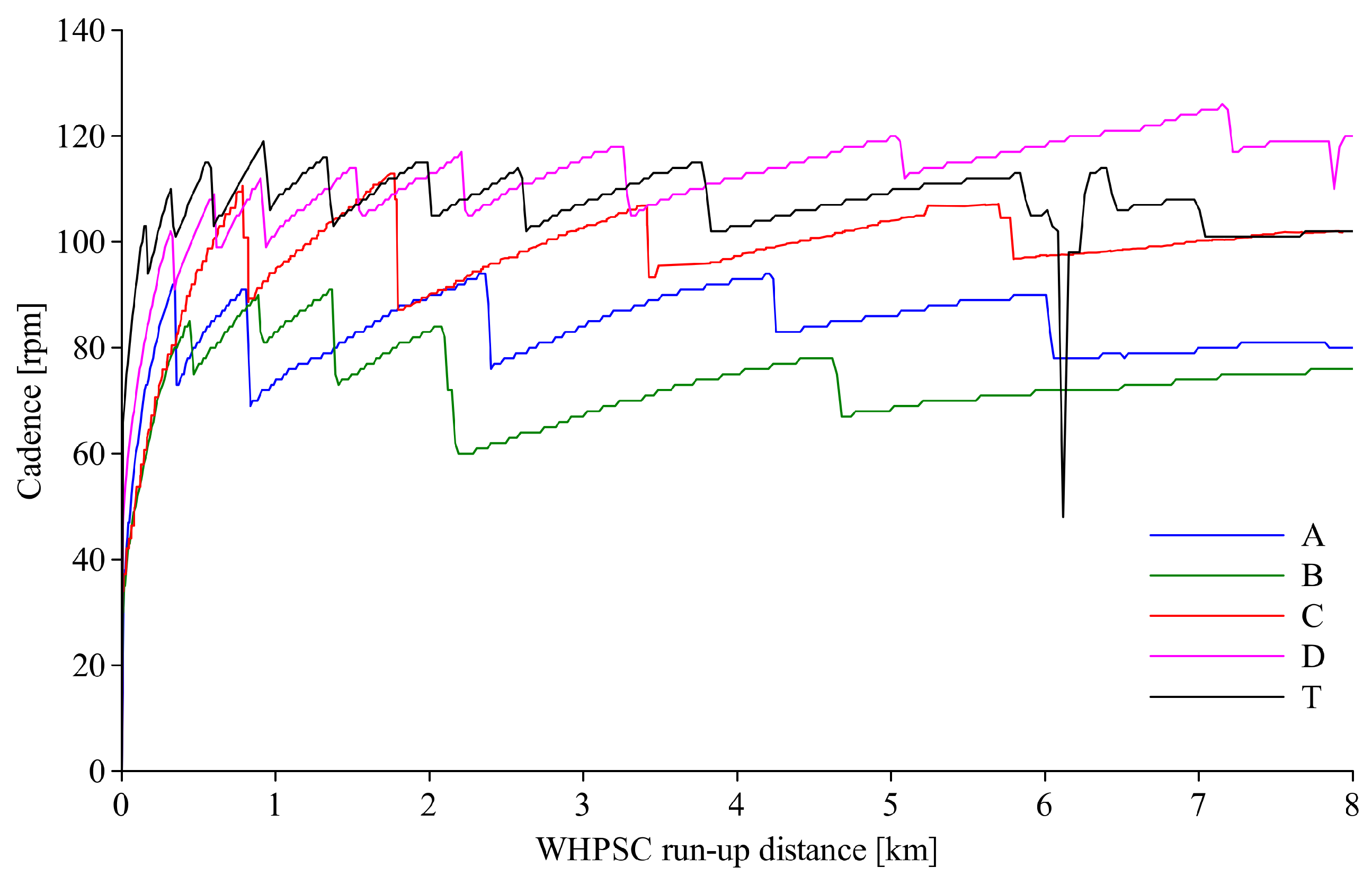
With the aim of assessing the benefits of the developed transmission, a comparison with some run data made available by other WHPSC competitors over years is presented. These data were shared in private communications with the authors under agreement of publishing them anonymously with respect to team, rider and vehicle, thus they are generically indicated as A, B, C, D while the solution presented in this article is referred as T (Taurus). Known characteristics of the compared vehicles are summarized in
Table 2.
Since the data come from vehicles with different characteristics (, A, , m, , crank length and gear ratios) and ridden by athletes with different average and maximum power, some consideration is necessary to correctly proceed in a comparison. The initial goal of the project was to avoid large falls in cadence allowing the cyclist to express his power around an optimal pedaling rate. Therefore, the following comparative analysis focuses on cadence data without considering the reached speed, which is instead the result of the overall characteristics of the vehicle combined with the power expressed by the cyclist.
Assuming that each team developed the vehicle transmission in order to work, at regime, around an optimal cadence that depends on the rider size [
41], it is considered a benefit to reduce the cadence drop at each gear change and, in general, to keep the pedaling rate within a narrower range during the whole effort.
A comparison of the obtained data is shown in
Figure 9 and a statistical analysis of cadence in the regime section (excluding the first gear ramp and intentional pedaling pauses) is reported in
Table 3. From the plot it is evident that, in the very first part of the run (0.5 km), the solution presented in this article (T) allows the rider to reach the regime cadence faster than the others, thanks to the increased number of gears, resulting in higher chances to express significant power since the early stage of the run-up. Moreover, the statistical analysis in
Table 3 highlights that the developed solution allows the rider to pedal in a smaller range of cadence at regime, which means always close to his optimal value.
5. Further Developments
Recently, the project won a Proof of Concept (PoC) grant for developing a version focused on the standard bicycle market. The current evolution under the PoC grant, named MOCA (from Moving Cassette), has been developed towards full integration of the actuation system inside the splined shaft. A general overview of this evolution is shown in
Figure 10, but further details cannot be shown here to preserve the possibility of a new patent application.
As usually happens when facing the consumer market, the project needs to overcome obstacles that are not only technical. First, the real value proposition has to be identified and proved by answering many questions:
Is the marginal gain in efficiency worthwhile?
Is the reduction in wear of transmission components effective? Is it a significant aspect for the final customer?
Is the system failure by chain dropping 100% solved with the alignment? Is it a perceived issue for the current traditional bicycle gear shifters?
Moreover, even if these doubts were to find a positive answer, to adapt the system on standard bicycles, two important changes would be required on the frame and on the wheel hub (
Figure 10). The use of a dedicated and bell-shaped wheel hub is necessary to house the moving cassette. In the first prototype under construction, a custom rear frame was required to host the selected 12-speed cassette. This also resulted in a slight lengthening of the rear stay (430 mm, in contrast with the racing bike market trend) to avoid interference with the pedaling cyclist’s heel. Potentially, thanks to the constant chain alignment, the MO.CA. allows for any number of pinions (even 15), provided the acceptance of an even larger rear dropout width.
A recently born spin-off company (Gregario—Cycling Development Lab), focused on bringing innovative products to the bicycle market, will negotiate a patent licence with the aim of further developing the project and to find an answer to the above questions.
6. Conclusions
In this paper, the need to develop an electronic bicycle shifter with moving cassette within a niche competition context for HPVs is explained. The evolution of the project across two years including a first working solution and a second improved version is detailed since the early design phase. The first prototype limitations are discussed, highlighting the non-linearity of the actuation system, the inadequate accuracy of the position feedback sensor and the occasional shifting errors that emerged in both testing and racing conditions. The need to overcome these issues led to a project revision that proved to be effective and contributed to a significant result in the context of an international competition. A comparison with data from other competitors shows that the solution allows for smaller standard deviation and variance in cadence, enabling the rider to pedal around his optimal pedaling rate for the whole run-up and to reach the regime cadence faster at start.
Further developments towards implementation of the electronic moving cassette shifter on traditional bicycles are presented with an overview of the emerging critical aspects with respect to market standards.
The next step in the project development is the ongoing construction of a prototype bicycle with quasi-standard geometry to host the third design. Then, procedures are being defined to perform both laboratory and road testing for assessing functionality, reliability and robustness of the system, including electrical insulation from rain, battery endurance and shifting speed. Moreover, a market analysis on some specific segments will be carried out to understand if the product can meet customer requirements, i.e. in the field of triathlon bicycles or hand-bikes for paralympic athletes.


