Abstract
In this paper, the critical speeds of a rotating shaft fitted with eccentric balance sleeves are identified from a scaled, high speed experimental test facility. The results are compared with the results of dynamic finite element simulations. It is shown that the stiffness of the sleeves must be accommodated when considering passive control characteristics critical speeds of a rotating shaft using eccentric sleeves.
1. Introduction
The analysis presented in the paper considers industrial shaft machinery that rotates at high speeds, specifically the rotating shaft in sub-15MW industrial gas turbine units, typically used for power generation or mechanical drive purposes. Operation of such machinery is accompanied by vibration, attributable in part to mass unbalance due to asymmetry and manufacturing imperfection in the rotating shaft, resulting in forces being exerted on surrounding structures [1]. It is vitally important to ensure that such forces are controlled by eliminating the geometric unbalance of the rotor where possible. Primarily this is achieved through design and high tolerances in manufacture [2]. Nevertheless, this is frequently insufficient and other means of reducing vibration levels are necessary post-manufacture.
Safe operation is ensured by adherence to regulation, such as API 671, which dictates that, in the case of a flexible coupling shaft, the lateral critical speed (LCS) margin should be 1.5 times the maximum operating speed [3,4]. Therefore, the flexible coupling shaft design is dictated by the LCS margin, resulting in couplings, which are more flexible than would otherwise be desirable. This in turn results in shafts that are difficult to dynamically balance across a wide range of operating speeds. As such, rotor unbalance is a commonly encountered issue in rotating machinery, requiring periodic remediation. Vibration-based identification and characterization of rotor unbalance and other faults in rotating machines has been the subject of numerous studies [5]. A model-based method for the estimation of multi-plane unbalance and misalignment in a rotating shaft from a single machine rundown was proposed by Sinha et al. [6]. The method was applied to a small, experimental test-rig, with a sensitivity analysis showing the robustness of the method, particularly with regard to phase estimation. Sudhakar et al. proposed a model based methodology for the identification of rotor unbalance in an experimental rotor bearing system utilizing two approaches: equivalent loads minimization and vibration minimization [7]. Considering errors in phase and amplitude estimation, it was concluded that the combined equivalent loads and vibration minimization method was more effective than the equivalent loads minimization method alone. More recently, a method for the identification and optimization of unbalance parameters in rotor-bearing systems was proposed by Yao et al. [8]. The method combined a modal expansion approach with optimization algorithms and allowed for the identification of the axial location of the unbalance, as well as its magnitude and phase, showing good agreement with experimental observations.
Once the degree of residual unbalance in the rotor in terms of amplitude and phase has been established, conventional corrective balancing techniques then involve the addition or subtraction of mass at specified locations [9,10]. This is typically done using a series of fixed balancing flanges on the shaft. Knowles et al. proposed an alternative method in which balance corrections are applied to the free ends of a pair of balancing sleeves, attached to each end of the rotating shaft [11,12].
By this means, the trim balance mass applies a corrective centrifugal force to the drive shaft to limit the shaft end-reaction forces. The balancing sleeves are flexible by design; as such, the magnitude of the correcting forces is greater at higher speeds due to the increasingly eccentric position of the trim balance mass. The sleeves also impart a corrective bending moment to the rotating shaft, which has a beneficial tendency to limit the shaft deflection [13]. However, the addition of mass to the system in the form of a sleeve can result in a change in the natural frequency and hence the critical speed of the system. Significant research is required to analyze the behavior of the system due to the addition of the eccentric sleeves prior to embedding them into engines. From this analysis, additional passive control characteristics may be identified.
In this paper, the critical speeds of a rotating shaft fitted with eccentric balance sleeves are identified from a scaled, high speed experimental test facility. The results are compared with the results of dynamic finite element simulations. It is shown that the stiffness of the sleeves must be accommodated when considering passive control characteristics critical speeds of a rotating shaft using eccentric sleeves.
2. Methodology
2.1. High Speed Test Facility
A high speed test facility was designed for this work, as shown in Figure 1. It consisted of two induction motors (QDI13.2-2F, Oswald Elektromotoren GmbH, Miltenberg, Germany). The motors were supplied by a 415 V three phase supply and were capable of producing 49 kW with a maximum operating speed of 20,000 rpm. The motors were controlled using a Unidrive SP AC Drive A and positive feedback was provided using a rotary encoder (512 bit PPR TTL 5 V Quadrature encoder, Heidenhaim Corporation, Traunreut, Germany).
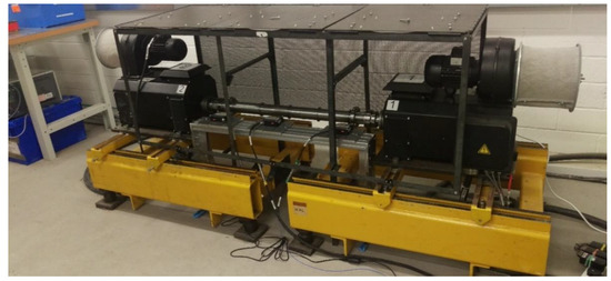
Figure 1.
High speed test facility.
The motors were mounted on engine support frames that were bolted to the floor on vibration isolation feet.
2.1.1. Test Shaft and Eccentric Sleeve
A test shaft linked the motors in the high speed test facility together. The shaft was dimensionally scaled from a full sized SGT-400 MD coupling shaft. The shaft assembly consists of two hubs, four adaptors, two flexible element packs, two eccentric balance sleeves and a single spacer shaft, as shown in Figure 2.
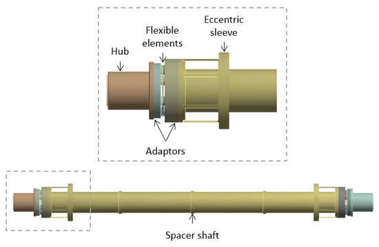
Figure 2.
Test shaft and eccentric sleeve.
The spacer shaft length was 920 mm and inner and outer diameters 56 and 62 mm, respectively. The shaft assembly hubs were fitted directly onto the motors with short, solid shafts. An interference fit was provided by use of two externally fitted Tollock couplings. The spacer shaft, adaptors and eccentric balance sleeves are constrained by the flexible element section of the coupling. The flexible element constrains axial displacement and rotation but allows for limited rotation about the y- and z-axes. The stiffness of the flexible elements was found to be 1 × 10⁴ N/m. The material properties of the shaft assembly components are given in Table 1.

Table 1.
Material properties.
To investigate the effect of sleeve flexibility on the dynamics of the system, three eccentric sleeves of varying length were designed a manufactured, as detailed in Table 2.
Table 2.
Sleeve lengths used in analysis.
Shaft balancing was conducted by the manufacturer prior to delivery. Table 3 summarizes the residual unbalance in each of the four eccentric balance sleeve configurations considered as supplied in manufacturer’s certificate of conformity.
Table 3.
Residual unbalance in test shaft/sleeve configurations.
2.1.2. Instrumentation
Shaft and sleeve deflections were measured using three laser displacement sensors (optoNCDT ILD2300-20, Micro-Epsilon Messtechnik GmbH & Co. KG, Ortenburg, Germany), as shown in Figure 3. The displacement sensors allowed for high accuracy measurement (<1 μm) with a sampling rate of up to 50 kHz.
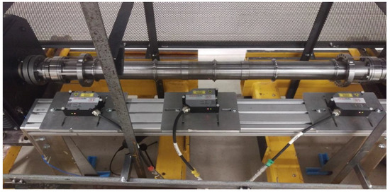
Figure 3.
Laser displacement sensors measuring shaft.
2.2. Finite Element Model Development
A dynamic finite element model of the full rotating shaft and eccentric sleeve system has been developed in ANSYS Workbench (Version 17.0). A modal analysis was carried out using a rotating coordinate system. An appropriate meshing strategy was obtained using a convergence study. All components were meshed using 10 node higher order 3D (SOLID187) elements, as shown in Figure 4.
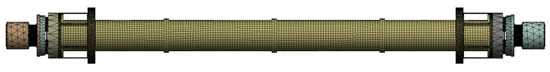
Figure 4.
Meshed geometry.
The model was fixed at each end to replicate connection to driving and driven equipment using a remote displacement scoped to the hubs, constraining translational motion and rotation about the y- and z-axes. A rotational velocity was applied about the x-axis.
To investigate the effect of sleeve flexibility on the dynamics of the system, finite elements models incorporating the three lengths of eccentric sleeve detailed in Table 2 were created. Models were also created in which the geometry of the eccentric sleeves was removed and replaced with a point mass with equivalent inertia properties. This allowed for the effect of the mass of the sleeve on the dynamics of the system to be considered in the absence of any stiffness effects.
3. Results and Discussion
The experimental work focussed on determining the critical speeds of the shaft for four eccentric balance sleeve configurations: no sleeve, short sleeve, medium sleeve and long sleeve. The numerical work focussed on ascertaining the effect of sleeve flexibility on the dynamics of the system.
3.1. Experimental Results
The critical speeds of the system were identified by determining its peak response in terms of measured shaft displacement (v) at the mid-point for each of the four eccentric balance sleeve configurations considered with respect to rotational velocity, assuming only unbalance excitation resulting in forward synchronous whirl. Previous studies have utilized mounted, wireless accelerometers for on shaft vibration measurement to determine the natural frequencies during run-up, allowing for the construction of experimentally-determined Campbell diagrams to identify the critical speeds [14,15]. However, the high rotational velocities used in this study necessitate that the critical speeds are inferred from the peak response. Figure 5 shows example shaft displacement (v) measurements at the mid-point for each of the four eccentric balance sleeve configurations considered with respect to rotational velocity. During run-up, a 10 s record of shaft deflection at steady state speed was taken at 100 rpm intervals between 0 and 12,000 rpm. Symmetry of orbit and centering of shaft displacement were checked and a mean displacement obtained for each data set.
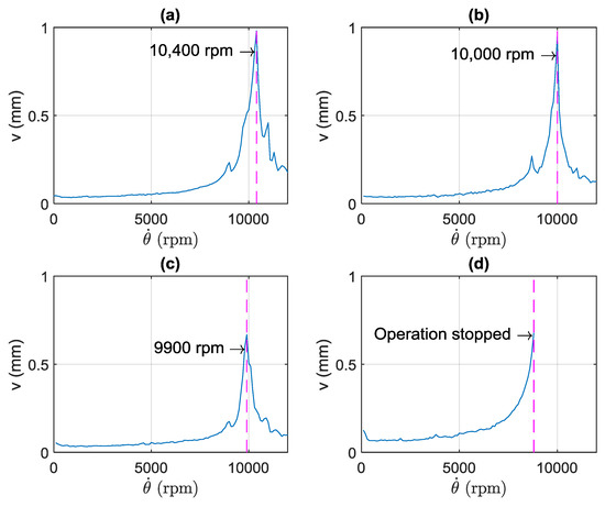
Figure 5.
Raw displacement data from the shaft for different sleeve configurations: (a) no sleeve, (b) short sleeve, (c) medium sleeve and (d) long sleeve.
Figure 5a–c reveals a reduction in critical speed and maximum transverse displacement with increasing eccentric balancing sleeve length. Operation of the long sleeve configuration was stopped at 8600 rpm due to unacceptably high levels of shaft and base vibration, as shown in Figure 5d. This could be attributed to the increased flexibility of the sleeve and resultant high vibration of the sleeve itself.
3.2. Numerical Results
Shaft critical speeds were obtained by modal analysis and Campbell diagrams. Natural frequencies ( were obtained for rotational velocities () of between 0 and 12,000 rpm. Figure 6 and Figure 7 show the Campbell diagrams for both the full geometry and point mass simulations for the first bending mode of the shaft. For the purposes of clarity, the natural frequencies have been normalised with respect to the non-rotating natural frequency for each configuration. The natural frequencies of the system were obtained using a rotating coordinate system, with the critical speeds determined as the speed at which the frequency of the mode becomes zero [16]. A forward whirling, synchronous critical speed in a stationary coordinate system is determined by the coincidence of a forward whirling mode with the excitation frequency. However, when observed in a rotating coordinate system, the same critical speed corresponds to zero frequency. Table 4 provides a summary of the critical speeds for each of the four eccentric balance sleeve configurations for both the full geometry and point mass simulations, as well as the experimental results.
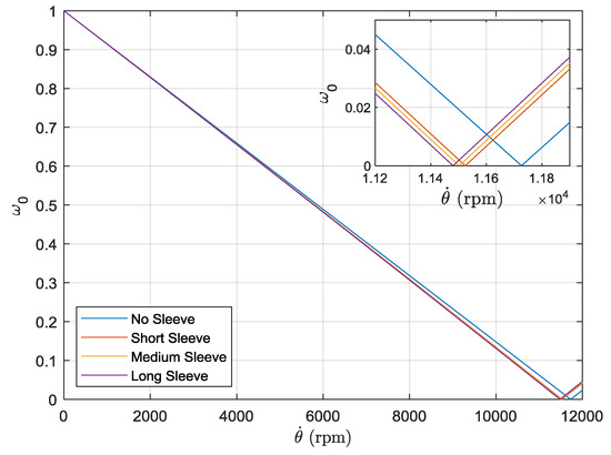
Figure 6.
Campbell diagram for finite element model with point masses. Inset shows natural frequencies and rotational velocity close to critical speeds.
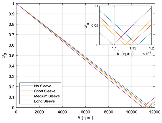
Figure 7.
Campbell diagram for the full geometry finite element model. Inset shows natural frequencies and rotational velocity close to critical speeds.
Table 4.
Summary of shaft critical speeds.
Comparison of the Figure 6 and Figure 7 and results in Table 4 show a disparity in the relative change of critical speed between the two simulations. The point mass simulation shows a marked decrease in critical speed with the addition of the short sleeve but no further significant change with the addition of sleeves of increasing length. By contrast, the full geometry shows a continuing decrease in critical speed with the addition of sleeves of increasing length, consistent with the experimental observations. This discrepancy between the simulation results can be attributed to the point mass simulation only considering the mass/inertia effects of the sleeves, as opposed to the full geometry simulation which accounts for stiffness effects on the system. The effect of increasing sleeve length on stiffness can be readily observed in the mode shapes of the system under free vibration, as shown in Figure 8, Figure 9 and Figure 10. For the short sleeve, the deflection of the sleeve is roughly equal to that at the same point on the shaft; essentially it is rigid. However, as the length of the sleeve is increased, the deflection becomes significantly greater than that of the shaft at the same point. This can be rationalized by considering that, as the sleeve increases in length, it becomes more flexible. This indicates that sleeve flexibility becomes progressively more influential on the dynamics of the system as sleeve length increases.
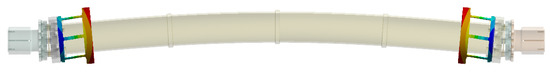
Figure 8.
Finite element obtained first bending mode of shaft with short sleeve.
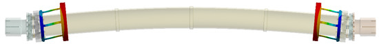
Figure 9.
Finite element obtained first bending mode of shaft with medium sleeve.
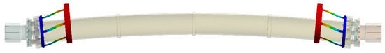
Figure 10.
Finite element obtained first bending mode of shaft with long sleeve.
3.3. Modifications to the Finite Element Model
Table 4 reveals that both the full geometry and point mass simulations overestimate the critical speed for all sleeve configurations. This can be attributed to the increased length of the entire drive train when the electric motor rotor shafts are considered, as well as the existence of bearings within the motors. The combined effect of this is a reduction in the critical speed of the shaft.
Modifications were made to the finite element model detailed in Section 2.2 to include the effects of the support structures. The motor casing was 450 mm in length, whilst the internal motor rotor shafts were 250 mm long. The rotor shaft was supported by two bearings, one mounted at the front edge of the motor casing, with the other at end of the shaft. The remainder of the motor casing was empty to aid ventilation and prevent overheating. Figure 11 shows the shaft with the motor shafts and bearings modelled as well as an outline internal schematic of the motor casing.
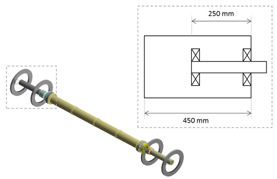
Figure 11.
Modified finite element model including support structures.
Based on the work conducted in [17], a parametric study was conducted in which the lateral stiffness of the bearings was altered and the critical speed of the first bending mode recorded. Damping and cross coupling terms were not included. A critical speed map is shown in Figure 12. For the no-sleeve configuration, the experimental critical speed was found to be 10,400 rpm. To obtain a matched critical speed in the modified finite element model, the critical speed map indicates that a bearing stiffness of 3.5 × 10⁷ N/m should be incorporated. This is consistent with the nominal stiffness for the type of bearings used (spindle) of between 1 × 10⁷ to 1 × 10⁸ N/m.
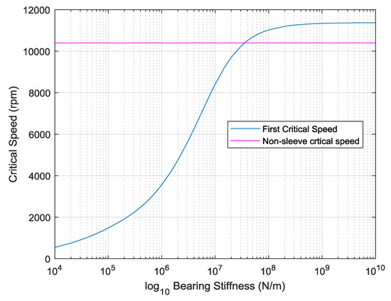
Figure 12.
Critical speed map for first bending mode for no-sleeve configuration.
The critical speeds for each of the four eccentric balance sleeve configurations and all experimental and model variants are shown in Figure 13. The results for the model, which does not account for sleeve flexibility (point mass simulation) fall outside of the 100 rpm tolerance of the experimental measurement and do not exhibit a strong correlation with the trend of the experimental data. The models, which include sleeve flexibility (full geometry and modified simulations) provide the best qualitative correlation with the experimental results, indicating that sleeve flexibility plays an important role in determining the critical speeds of the combined shaft system. Through the inclusion of support structures in the modified simulation, the simulated critical speeds were brought to within the 100 rpm tolerance of the experimental measurement.
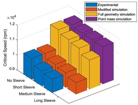
Figure 13.
Critical speeds for all modelling approaches and experimental.
4. Conclusions
A detailed experimental and numerical study into the use of an eccentric sleeve mechanism for the passive control of the critical speeds of a rotating shaft has been conducted. The addition of an eccentric balancing sleeve to a rotating shaft has been shown to reduce the critical speed of the shaft. Increasing the length of the eccentric balancing sleeve length was shown to further reduce the critical speed of the shaft through modification of the mass and stiffness characteristics of the system.
The results of dynamic finite element simulations that neglect sleeve flexibility show poor correlation with experimental measurements when compared with results from simulations in which the full geometry was modelled. The inclusion of support structures incorporating bearing stiffness in the full geometry finite element models yielded results that were within the 100 rpm margin of error in the experimental measurement. This indicates that mass/inertia effects alone are not sufficient to describe the change in critical speed as eccentric sleeve length is increased and sleeve flexibility is an important parameter in the passive control of the shaft critical speeds.
Author Contributions
Conceptualization, A.K.; methodology, A.K.; software, A.K.; validation, A.K. and J.G.; formal analysis, A.K. and J.G.; investigation, A.K. and J.G.; writing—original draft preparation, A.K.; writing—review and editing, J.G.
Funding
This research was funded by Siemens Industrial Turbomachinery Ltd.
Conflicts of Interest
The authors declare no conflict of interest.
References
- Adams, M.L. Rotating Machinery Vibration, 2nd ed.; CRC Press: Boca Raton, FL, USA, 2010. [Google Scholar]
- Chuan, M.; Changsheng, Z. Unbalance Compensation for Active Magnetic Bearing Rotor System Using a Variable Step Size Real-Time Iterative Seeking Algorithm. IEEE Trans. Ind. Electron. 2018, 65, 4177–4186. [Google Scholar] [CrossRef]
- American Petroleum Institute. AQPI Standard 617—Special Purpose Couplings for Petroleum, Chemical and Gas Industry Services; American Petroleum Institute: Washington, DC, USA, 2017. [Google Scholar]
- Meeus, H.; Verrelst, B.; Moens, D.; Guillaume, P.; Lefeber, D. Experimental Study of the Shaft Penetration Factor on the Torsional Dynamic Response of a Drive Train. Machines 2018, 6, 31. [Google Scholar] [CrossRef]
- Lees, A.W.; Sinha, J.K.; Friswell, M.I. Model-based identification of rotating machines. Mech. Syst. Signal Process. 2009, 23, 1884–1893. [Google Scholar] [CrossRef]
- Sinha, J.K.; Lees, A.W.; Friswell, M.I. Estimating unbalance and misalignment of a flexible rotating machine from a single run-down. J. Sound Vib. 2004, 272, 967–989. [Google Scholar] [CrossRef]
- Sudhakar, G.N.D.S.; Sekhar, A.S. Identification of unbalance in a rotor bearing system. J. Sound Vib. 2011, 330, 2299–2313. [Google Scholar] [CrossRef]
- Yao, J.; Liu, L.; Yang, F.; Scarpa, F.; Gao, J. Identification and optimization of unbalance parameters in rotor-bearing systems. J. Sound Vib. 2018, 431, 54–69. [Google Scholar] [CrossRef]
- Morton, P.G. Modal balancing of flexible shafts without trial weights. IMechE Part C Mech. Eng. Sci. 1985, 199, 71–78. [Google Scholar] [CrossRef]
- Parkinson, A.G. Balancing of rotating machinery. IMechE Part C Mech. Eng. Sci. 1991, 205, 53–66. [Google Scholar] [CrossRef]
- Knowles, G.; Kirk, A.; Stewart, J.; Bickerton, R.; Bingham, C. Theoretical investigation into balancing high-speed flexible shafts, by the use of a novel compensating balancing sleeve. IMechE Part C 2014, 228, 2323–2336. [Google Scholar] [CrossRef]
- Kirk, A.J.; Griffiths, J.; Bingham, C.; Knowles, G.; Bickerton, R. Passive Control of Critical Speeds of a Rotating Shaft Using Eccentric Sleeves: Model Development. In Proceedings of the 2016 ASME Turbo Expo, Seoul, Korea, 13–17 June 2016; Volume 7A, p. V07AT32A034. [Google Scholar]
- Knowles, G.; Kirk, A.; Bingham, C.; Bickerton, R. Generalised analysis of compensating balancing sleeves with experimental results from a scaled industrial turbine coupling shaft. IMechE Part C 2017, 232, 3453–3468. [Google Scholar] [CrossRef]
- Elnady, M.E.; Sinha, J.K.; Oyadiji, S.O. Identification of Critical Speeds of Rotating Machines Using On-Shaft Wireless Vibration Measurement. J. Phys. Conf. Ser. 2012, 364, 012142. [Google Scholar] [CrossRef]
- Elnady, M.E.; Abdelbary, A.; Sinha, J.K.; Oyadiji, S.O. FE and Experimental Modeling of On-shaft Vibration Measurement. In Proceedings of the 15th International Conference on Aerospace Sciences & Aviation Technology, Cairo, Egypt, 28–30 May 2013. Paper: ASAT-15-168-ST. [Google Scholar]
- Vollen, A.; Komzsik, L. Computational Techniques of Rotor Dynamics with the Finite Element Model; CRC Press: Boca Raton, FL, USA, 2012. [Google Scholar]
- Tiwari, R.; Lees, A.; Friswell, M. Identification of dynamic bearing parameters: A review. Shock Vib. Dig. 2004, 36, 99–124. [Google Scholar] [CrossRef]


© 2019 by the authors. Licensee MDPI, Basel, Switzerland. This article is an open access article distributed under the terms and conditions of the Creative Commons Attribution (CC BY) license (http://creativecommons.org/licenses/by/4.0/).