Abstract
The trade-off between the design phase and the experimental setup is crucial in satisfying the accuracy requirements of large deployable reflectors. Manufacturing errors and tolerances change the root mean square (RMS) of the reflecting surface and require careful calibration of the tie-rod system to be able to fit into the initial design specifications. To give a possible solution to this problem, two calibration methods—for rigid and flexible ring truss supports, respectively—are described in this study. Starting from the acquired experimental data on the net nodal co-ordinates, the initial problem of satisfying the static equilibrium with the measured configuration is described. Then, two constrained optimization problems (for rigid or flexible ring truss supports) are defined to meet the desired RMS accuracy of the reflecting surface by modifying the tie lengths. Finally, a case study to demonstrate the validity of the proposed methods is presented.
1. Introduction
Satellite communications have become increasingly wide-spread, thanks to the possibility of having high transmitting capacities at a relatively low cost, compared to the establishment of a terrestrial broadcasting network. Deployable reflectors represent the most widely-used type of structure, due to their features, such as large scale, high packaging efficiency, high accuracy, and low weight. Typically, their architecture consists of a deployable ring truss support, two cable nets (facing each other and linked by a series of tension ties), and a RF mesh attached to the backside of the front net. The most representative kind of this type of reflector is the AstroMesh [1], and its components are shown in Figure 1.
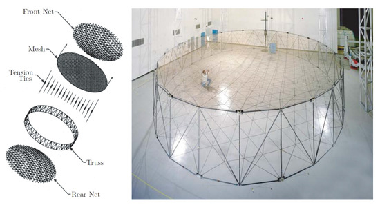
Figure 1.
AstroMesh.
The electromagnetic performance of these antennae is closely related to the shape of the reflector surface. In turn, this depends on the position of the nodes located on the front net. Therefore, it is clear that the measurement process of 3D node co-ordinates needs to be made with extreme accuracy, so as to avoid invalidating the real root mean square (RMS) value.
Several measurement systems have been developed, depending on the application area. Generally, they can be divided into three categories:
- Photogrammetry,
- Laser tracker, and
- Laser radar.
Photogrammetry is a measurement technique that uses two-dimensional images of an object to obtain its dimensions.
As depicted in Figure 2, photogrammetry is based exclusively on angle measurements: Three-dimensional co-ordinates are calculated by an optical triangulation (or intersection) of two or more images taken from different positions. The object to be measured is identified by targets mounted on it, usually made of reflective material to produce a high contrast between the target and the background [2]. Typically, a calibrated scale bar is integrated into the object, in order to reproduce it in true scale. At the end of the measurements, a dedicated software calculates the 3D co-ordinates in the chosen Cartesian co-ordinate system (x, y, z).
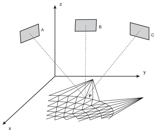
Figure 2.
Photogrammetry.
Laser trackers and laser radars, alternatively, are measurement systems based on the estimation of two angles and one length, as shown in Figure 3. Two high-resolution encoders measure the azimuth () and elevation () angles, whereas the radial co-ordinate (r) relative to the center of the target is measured by means of optical interference [3]. Several types of target can be mounted, but the most widely-used is the spherically mounted retro-reflector (SMR).
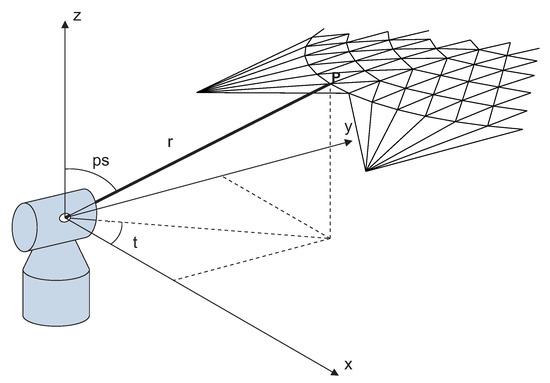
Figure 3.
Laser tracker.
Differing from the laser tracker, a laser radar does not require a retro-reflector. As a matter of fact, it is capable of measuring the surface of an object with just 1% of the reflected signal [4].
Each of these measurement systems, however, has advantages and disadvantages, which need to be assessed on the basis of various factors. Van Gestel et al. [4] identified influencing factors to be taken into account before making the measurement: Task requirements, part restrictions, and environmental restrictions. Regarding task requirements, the main element to be considered when measuring the position of the nodes is accuracy, since the permissible RMS error on the reflecting surface is less than 1 mm. Whilst the laser tracker has errors on the order of 1 m, it is too costly due to the high price of each SMR and given the number of nodes (at least a hundred). The photogrammetry turned out to be the best choice [5,6], considering the affordable cost and accuracy of the measure. Furthermore, the possibility of obtaining multiple images from different angles makes it possible to overcome the lower accuracy of the angular encoders of laser trackers.
The acquisition of node co-ordinates is essential for the next calibration step, in order to meet the RMS design requirements of the reflecting surface. Generally, the main strategies followed by LDR developers and designers is to use the tie system, connecting front and rear nets, in order to locally move single nodes. This operation is long and delicate, but allows the adjustment of different error sources, such as manufacturing errors [7,8,9], material definition errors, clearance [10,11], friction [12,13], hysteresis [14], mechanical vibrations [15,16], and imperfect behaviour of the elastic properties of components. This paper describes a method for the tie-system calibration of LDRs with a rigid or flexible ring truss. To our knowledge, this topic has not been deeply investigated in the literature and the adjustment phase is entrusted with proprietary solutions of LDR companies. The outline of this paper is as follows. In Section 2, the problem of correcting the parameters to satisfy the static equilibrium in the deployed configuration is first addressed. Then, the method for finding the necessary corrections to the tie-system is discussed, for the two cases of LDR (i.e., with rigid or flexible ring truss). In Section 3, the method is applied to a LDR with an asymmetric ring truss, developed by Thales Alenia Space. A simulated error distribution is superimposed to the design configuration to represent a real experimental test. The tie-system corrections (expressed in terms of length elongation or shortening) necessary to meet RMS design requirement are obtained for both rigid and flexible ring truss cases. Finally, in Section 4, the conclusions of the paper are presented.
2. Experimental Settings for Calibration
Once the antenna has been manufactured, it is necessary to carry out some experimental tests in order to check the RMS of the reflector in the deployed configuration. To do this, the first operation consists of measuring the position of all nodes of the nets with respect to a reference system through one of the methods described above. Due to different sources of errors, such as manufacturing errors or assembly errors, the deployed configuration will be different from the design configuration and the RMS will usually be greater than the design requirement. Even the measurement operation of the node co-ordinates will be affected by errors. Laser trackers and photogrammetry have errors on the order of 1 m; while laser radar reaches m. Errors related to the measurement systems are, regardless, significantly below the preceeding mechanical errors. In the following, two methods for the experimental setting of the rigid and flexible ring truss supports are described.
Several experimental methodologies [17,18,19,20] based on a multi-body approach have been developed [21,22,23,24,25,26,27,28,29]. Recently, methods based on fuzzy logic [30,31,32,33,34], neural networks [35], and genetic algorithms have been applied for the tensioning of space trusses [36,37]. The proposed methods act on the tensioning system of the ties in order to fix the errors coming from the construction of the antenna.
2.1. Rigid Ring Truss Support: Construction Length Determination
Tie-cable regulation is usually independent of the actuators used for the LDA deployment [38,39,40] and from the control system [41,42,43,44]. Here, the method to regulate tie cable tension in an antenna with rigid ring truss support is first described. Once the deployment has been carried out and all node co-ordinates of the net have been measured, the reflective surface will typically deviate from the design configuration due to mechanical errors. As a consequence of this deviation, the system of equilibrium equation is not satisfied for the current configuration. Then, denoting with , , , and the Young modulus, the cross-section area, the measured length, and the construction length of cable , respectively, and with , , and the spring constant, the measured length, and the construction length of tie , respectively, the system of nonlinear equations for each free node i, with j adjacent nodes, is not satisfied:
where , , and are the measured Cartesian co-ordinates of the l-th node. It is noteworthy to remark that the only measured parameters are the node co-ordinates; while the measured length is derived using the Euclidian norm. The remaining parameters of the previous system are design parameters, instead; each affected by different types of error. Here, denoting by and the measured and construction length for both cable and tie, respectively, we choose to gather all these errors inside the construction length , defined as the distance between the centers of the eyelets i and j belonging to the same cable, as shown in Figure 4. This choice is motivated by the fact that the construction length of the cables is affected by two main sources of errors, such as the manufacturing errors generated during the cutting operation of (Computer Numerical Control) CNC machines [45], and the assembly errors coming from the bad placement of the eyelets (which are necessary to connect two or more cables). In order to restore the equilibrium condition in System (1), only the design parameters can be adjusted, while the measured parameters describe the real configuration of equilibrium: The measured configuration is already in equilibrium and, thus, System (1) is to be satisfied in this configuration without changing the node co-ordinates.

Figure 4.
Layout of a cable: The construction length is affected by manufacturing errors generated during the cutting operation and assembly errors coming from a bad placement of the eyelets necessary to connect two or more cables.
Then, as each cable works in traction force only, the constraint must be imposed. To solve the system of nonlinear equations, Matlab provides the command fsolve, but it does not allow the inclusion of any constraints. To overcome this problem, the nonlinear programming solver fmincon can be used by giving a constant objective function and setting (1) as the nonlinear equality constraint, in addition to the linear inequality constraint . The resulting constrained optimization problem is described below:
Hence, a first check is required. As the springs used in tension ties require a pre-stress value, here denoted by , representing the minimum value necessary for their activation, the condition for each tension tie cable must be verified, where
is the spring force of tie . If the condition is satisfied, the next step can be conducted; otherwise, the spring belonging to the tie which has failed the test must be replaced and the algorithm starts again by calculating the array of all construction lengths.
2.2. Rear Node Determination
In the event that only the co-ordinates of the nodes of the front net are known by measurement, before implementing the algorithm described above, the rear node co-ordinates have to be estimated. Their co-ordinates are initialized with the design data and System (1) is implemented for each free node of the front and rear net. Note the dualism between the two methods: In the former, the unknowns are the construction lengths; in the latter, they are the rear node co-ordinates. Next, the construction lengths are obtained as a consequence of using the Euclidian norm. We checked that both methods lead to the same results (except for negligible errors) if the experimental configuration is not too distant from the design one.
2.3. Rigid Ring Truss Support: Tie Calibration
Once the configuration satisfying the static equilibrium has been found, the algorithm continues with the estimation of the values of stretching or shortening for each tension tie-cable, which ensures that the surface accuracy of the reflector can be met. Figure 5 shows the screw adjustment system for a tie. One fixed part is connected to a node of the front net, while one mobile part—adjustable with a screw—is connected to a node of the rear net. Now, the system of nonlinear equations of each free node i can be written as follows:

Figure 5.
Screw adjustment in the tie system: (left) Tie system before adjustment; and (right) tie system after the screw regulation.
This system, similar to (1), is used to determine the vector , with the difference that the variables to be found are the stretching/shortening values and the co-ordinates of the free nodes of the front and rear net. The values can be positive or negative: Here, we assume positive values for tie-shortening and negative for tie-stretching. Additionally, this system is subject to some constraints: One condition for all net cables is . For the tension tie-cables, for which the values are to be considered, the constraint condition is that the final force must be one of traction:
Finally, the third constraint is related to the surface accuracy, since the RMS error must be lower than the desired design value . This is a typical constrained optimization problem, largely used in the design optimization of complex systems [46,47,48,49] and mechanisms [50,51,52]. The optimization problem can be summarised as follows:
where , , and are the free node co-ordinates and is the array containing all corrections . The RMS is calculated by measuring the minimum distance of the free nodes of the front net, compared to the ideal surface of the paraboloid [53]. The initial condition for the free nodes is represented by their experimental measurement, while the guess value for is set equal to zero.
2.4. Flexible Ring Truss Support
The truss support is generally manufactured out of carbon fiber and it is, therefore, reasonable to consider truss deformation under the effect of the tension of the cable net.
The elastodynamic model of the flexible ring truss support can be found using analytic techniques combined with matrix structural analysis [54,55,56,57], elliptic integrals [58,59], FEM models [60,61,62], and flexible multibody formulations [63].
This implies the displacement of the nodes connected to the truss support, also called vertices, when the net system is tensioned. By considering the stiffness of the structure, the nonlinear system (4), described in the previous section, becomes as follows:
where c is the total number of cables connected to the i-th node; r is the number of rods; , , and are the unknown co-ordinates of the j-th vertex; and , , and are the initial co-ordinates of the vertex itself. The stiffness of the truss support can be represented as a three-dimensional bushing, with stiffnesses , and , connecting the rods to the vertex, as shown in Figure 6.
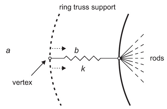
Figure 6.
Displacement of the vertex due to the deformation of the flexible ring truss support.
The constrained optimization (6) still applies to this flexible ring truss case and the overall algorithm is summarised in the flowchart in Figure 7.
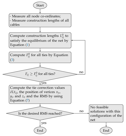
Figure 7.
Flowchart for the algorithm of the proposed method. RMS, Root Mean Square.
3. Results
In order to verify the validity of the proposed method, a case study of an asymmetric large deployable reflector, designed by Thales Alenia Space [53], is described. The relevant parameters and geometric data are listed as follows:
- Focal length: 6 m
- Number of free nodes: 296
- Number of vertices: 14
- Number of total cables: 1044
- Cable section: 4 mm2
- Young modulus of cables: N/m2
- Initial RMS error: 0.5872 mm
- Design value of the RMS faceting error: 0.21 mm
The value of the spring constant for tie cables ranges from N/m to N/m, with a radial step of N/m starting from the centre (central node) to the outer ring cables. The initial RMS error on the front net was simulated by introducing an additional value to each node proportionally to the length of the tie connected to it. By imposing the equilibrium in System (1), we can determine the construction lengths described in Section 2. Nevertheless, from Figure 8 it can be noted that the maximum error obtained was about 1 mm, representing only 1% of the total cables; the largest percentage (86%) showed an error between 0.6 mm and 1 mm.
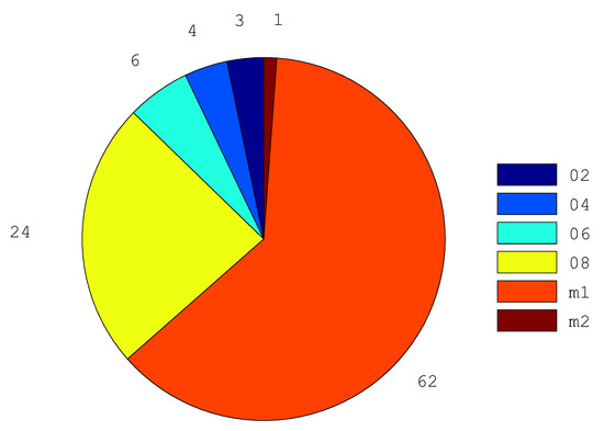
Figure 8.
Pie chart of the error (absolute value), grouped by measuring ranges (mm), between the measured construction lengths and those obtained by solving for equilibrium in System (1).
In Figure 9 the local faceting error for the chosen initial configuration is shown. The local faceting error is calculated by considering the centroid of the triangular facets into which the surface can be decomposed [64,65,66,67]. As can be observed, the faceting error follows the shape of the asymmetric reflector since the chosen error is proportional to the tie lengths. As a matter of fact, the central zone is the one with the shortest cables and, therefore, with the lowest faceting error. On the contrary, the tie lengths, and consequently the errors, grow; moving from the centre to the outer perimeter of the net.
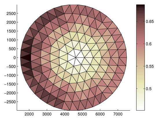
Figure 9.
Faceted RMS (mm) of the front tension truss in the initial configuration.
The optimization method described in the previous sections is first applied to the rigid ring truss support. Figure 10 shows the error of each free node of the front net with respect to the ideal surface, coupled with the stretching/shortening value necessary to reach the desired surface accuracy. The reason why the correction values are all positive is that the initial error is simulated by positioning all nodes of the front net above the ideal surface, so there is a need to shorten the tie lengths to satisfy the RMS design value. The bars are grouped by spring constant value.
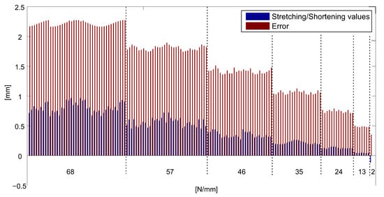
Figure 10.
Error and correction values (rigid case).
The corresponding faceting error is shown in Figure 11. As can be observed, the RMS of the faceting error decreases until the required value of 0.2036 mm is furnished, as per specification.
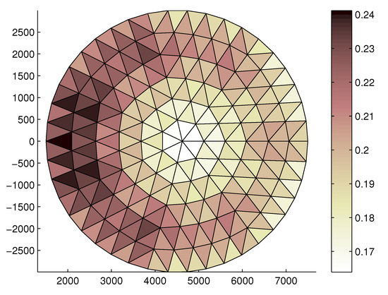
Figure 11.
Faceting error (mm) distribution on the front tension truss, obtained for the rigid ring truss support.
Then, the same analysis has been performed for the flexible ring truss support. It can be noted that, in Figure 12, the correction values are lower than the corresponding values for the rigid truss support: This is because the additional tensioning of ties further deforms the shape of the truss support, resulting in a closure of the support itself [68]. As a result, this causes a slight lowering of the front net, thus reducing the shortening action of the tie lengths. Finally, Figure 13 shows the faceting error distribution on the front net. Even in this case, the final RMS faceting error reached 0.2045 mm, representing the design value of the RMS. Comparing Figure 11 and Figure 13, it can be observed that the faceting error distribution is more uniform for the flexible ring truss support. This result can be explained by considering that the deformation of the truss support relaxes the front and rear tension truss systems, making the tension distribution more uniform.
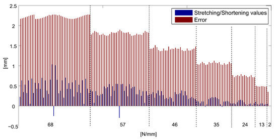
Figure 12.
Error and correction values (flexible case).
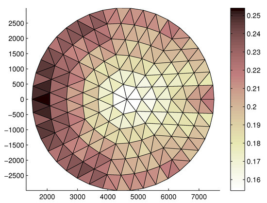
Figure 13.
Faceting error (mm) distribution on the front tension truss, obtained for the flexible ring truss support.
Moreover, other simulations with different initial RMS errors revealed that, with the given design data, the maximum initial RMS error which can be fixed is about 1 mm. Beyond this limiting value, a revision of the design data is needed. This demonstrates the validity of the method only for small RMS errors.
4. Conclusions
In this paper, a method for the tie-system calibration of large deployable reflectors (LDRs) is provided. The LDRs are very sensitive to errors and usually require a careful experimental setup to meet the design requirements for surface accuracy. Due to manufacturing errors, clearance, friction, and the imperfect behaviour of materials, the real configuration moves away from the design configuration and a fine calibration is needed to improve the quality of the reflecting surface, expressed in terms of closeness to the ideal paraboloidal geometry. The proposed method follows two steps: The determination of the parameters satisfying the static equilibrium in the real deployed configuration; and a fine calibration to meet the RMS design requirements. For the first step, a constrained optimization problem was proposed, in order to find the cable construction lengths once all node co-ordinates had been measured. The second step was developed by acting on the system of screw-adjustable ties. A further constrained optimization problem was formulated to find the length corrections of each tie. Using the same approach, the cases of LDR with a rigid or flexible tension truss were studied. Finally, the method was applied to a LDR with an asymmetrical ring truss designed by Thales Alenia Space. Considering an initial RMS of 0.58 mm, the results (not yet validated by experimental test) seemed comforting in reaching the design RMS. The convergence of the method depends on the starting and desired RMS. Here, the convergence was insured up to a reasonably high initial RMS value of 1 mm. Beyond this value, the tie system was not able to reach the equilibrium and satisfy the constraints, and a different solution should be adopted.
Author Contributions
This research paper was principally developed by the first and last author (A.C. and P.D.M.). The other two authors (R.S. and R.R.) have dealt with the significant review activity.
Funding
This research was funded by ESA grant number AO/1-7217/NL/CP—Innovative Scalable Large Deployable Antenna Reflectors.
Acknowledgments
This work has been partially financed by the University of Catania within the project “Piano della Ricerca Dipartimentale 2016–2018” of the Department of Civil Engineering and Architecture.
Conflicts of Interest
The authors declare no conflict of interest.
Abbreviations
The following abbreviations are used in this manuscript:
| MDPI | Multidisciplinary Digital Publishing Institute |
| DOAJ | Directory of open access journals |
| TLA | Three letter acronym |
| LD | linear dichroism |
References
- Thomson, M. AstroMesh™ deployable reflectors for ku and ka band commercial satellites. In Proceedings of the 20th AIAA International Communication Satellite Systems Conference and Exhibit, Montreal, QC, Canada, 12–15 May 2002; p. 2032. [Google Scholar]
- Estler, W.T.; Edmundson, K.; Peggs, G.; Parker, D. Large-scale metrology—An update. CIRP Ann. Manuf. Technol. 2002, 51, 587–609. [Google Scholar] [CrossRef]
- De Simone, M.C.; Guida, D. On the Development of a Low Cost Device for Retrofitting Tracked Vehicles for Autonomous Navigation. In Proceedings of the AIMETA, Salerno, Italy, 4–7 September 2017. [Google Scholar]
- Cuypers, W.; Van Gestel, N.; Voet, A.; Kruth, J.P.; Mingneau, J.; Bleys, P. Optical measurement techniques for mobile and large-scale dimensional metrology. Opt. Lasers Eng. 2009, 47, 292–300. [Google Scholar] [CrossRef]
- Dong, M.L.; Deng, W.Y.; Sun, Y.; Wang, Y. Photogrammetric Measurement of Deformation of Large Deployable Mesh Microwave Antenna. Key Engineering Materials. Trans. Tech. Publ. 2008, 381, 309–312. [Google Scholar]
- Stegman, M.D.; Fedyk, M.; Kuehn, S. Solar thermal vacuum testing of deployable mesh reflector for model correlation. In Proceedings of the 2010 IEEE Aerospace Conference, Big Sky, MT, USA, 6–13 March 2010; pp. 1–15. [Google Scholar]
- Zhang, Y.; Li, Z.; Gao, J.; Hong, J.; Villecco, F.; Li, Y. A method for designing assembly tolerance networks of mechanical assemblies. Math. Probl. Eng. 2012, 2012, 513958. [Google Scholar] [CrossRef]
- Villecco, F.; Pellegrino, A. Evaluation of uncertainties in the design process of complex mechanical systems. Entropy 2017, 19, 475. [Google Scholar] [CrossRef]
- Villecco, F. On the evaluation of errors in the virtual design of mechanical systems. Machines 2018, 6, 36. [Google Scholar] [CrossRef]
- Cammarata, A.; Lacagnina, M.; Sinatra, R. Closed-form solutions for the inverse kinematics of the Agile Eye with constraint errors on the revolute joint axes. In Proceedings of the 2016 IEEE/RSJ International Conference on Intelligent Robots and Systems (IROS), Daejeon, Korea, 9–14 October 2016; pp. 317–322. [Google Scholar]
- Cammarata, A. A novel method to determine position and orientation errors in clearance-affected overconstrained mechanisms. Mech. Machine Theory 2017, 118, 247–264. [Google Scholar] [CrossRef]
- De Simone, M.; Guida, D. Dry friction influence on structure dynamics. In Proceedings of the COMPDYN, Crete Island, Greece, 25–27 May 2015. [Google Scholar]
- De Simone, M.C.; Guida, D. Modal Coupling in Presence of Dry Friction. Machines 2018, 6, 8. [Google Scholar] [CrossRef]
- Guida, D.; Pappalardo, C.M. Control design of an active suspension system for a quarter-car model with hysteresis. J. Vib. Eng. Technol. 2015, 3, 277–299. [Google Scholar]
- Pappalardo, C.M.; Guida, D. Adjoint-based optimization procedure for active vibration control of nonlinear mechanical systems. J. Dyn. Syst. Meas. Control 2017, 139, 081010. [Google Scholar] [CrossRef]
- Pappalardo, C.M.; Guida, D. Control of nonlinear vibrations using the adjoint method. Meccanica 2017, 52, 2503–2526. [Google Scholar] [CrossRef]
- Pappalardo, C.M.; Guida, D. A time-domain system identification numerical procedure for obtaining linear dynamical models of multibody mechanical systems. Arch. Appl. Mech. 2018, 88, 1325–1347. [Google Scholar] [CrossRef]
- Pappalardo, C.M.; Guida, D. On the use of two-dimensional Euler parameters for the dynamic simulation of planar rigid multibody systems. Arch. Appl. Mech. 2017, 87, 1647–1665. [Google Scholar] [CrossRef]
- Pappalardo, C.M.; Guida, D. System Identification Algorithm for Computing the Modal Parameters of Linear Mechanical Systems. Machines 2018, 6, 12. [Google Scholar] [CrossRef]
- Pappalardo, C.M.; Guida, D. System Identification and Experimental Modal Analysis of a Frame Structure. Eng. Lett. 2018, 26. [Google Scholar]
- Cavacece, M.; Pennestri, E.; Sinatra, R. Experiences in teaching multibody dynamics. Multibody Syst. Dyn. 2005, 13, 363–369. [Google Scholar] [CrossRef]
- Callegari, M.; Cammarata, A.; Gabrielli, A.; Sinatra, R. Kinematics and dynamics of a 3-CRU spherical parallel robot. In Proceedings of the ASME 2007 International Design Engineering Technical Conferences and Computers and Information in Engineering Conference, Las Vegas, NV, USA, 4–7 September 2007; pp. 933–941. [Google Scholar]
- Cammarata, A.; Angeles, J.; Sinatra, R. Kinetostatic and inertial conditioning of the McGill Schönflies-motion generator. Adv. Mech. Eng. 2010, 2, 186203. [Google Scholar] [CrossRef]
- Barbagallo, R.; Sequenzia, G.; Oliveri, S.; Cammarata, A. Dynamics of a high-performance motorcycle by an advanced multibody/control co-simulation. Proc. Inst. Mech. Eng. Part K J. Multibody Dyn. 2016, 230, 207–221. [Google Scholar] [CrossRef]
- Barbagallo, R.; Sequenzia, G.; Cammarata, A.; Oliveri, S.; Fatuzzo, G. Redesign and multibody simulation of a motorcycle rear suspension with eccentric mechanism. Int. J. Interact. Des. Manuf. 2017, 12, 1–8. [Google Scholar] [CrossRef]
- De Simone, M.C.; Russo, S.; Rivera, Z.B.; Guida, D. Multibody model of a UAV in presence of wind fields. In Proceedings of the 2017 International Conference on Control, Artificial Intelligence, Robotics & Optimization (ICCAIRO), Prague, Czech Republic, 20–22 May 2017; pp. 83–88. [Google Scholar]
- Pappalardo, C.M.; Guida, D. Dynamic analysis of planar rigid multibody systems modeled using natural absolute coordinates. Appl. Comput. Mech. 2018, 12. [Google Scholar] [CrossRef]
- Pappalardo, C.M.; Guida, D. On the Lagrange multipliers of the intrinsic constraint equations of rigid multibody mechanical systems. Arch. Appl. Mech. 2018, 88, 419–451. [Google Scholar] [CrossRef]
- Pappalardo, C.M.; Guida, D. On the Computational Methods for Solving the Differential-Algebraic Equations of Motion of Multibody Systems. Machines 2018, 6, 20. [Google Scholar] [CrossRef]
- Ghomshei, M.; Villecco, F.; Porkhial, S.; Pappalardo, M. Complexity in energy policy: A fuzzy logic methodology. In Proceedings of the 2009 Sixth International Conference on Fuzzy Systems and Knowledge Discovery, Tianjin, China, 14–16 August 2009; Volume 7, pp. 128–131. [Google Scholar]
- Ghomshei, M.; Villecco, F. Energy metrics and Sustainability. In Proceedings of the 2009 International Conference on Computational Science and Its Applications, Yongin, Korea, 29 June 2009–2 July 2009; Springer: Berlin/Heidelberg, Germany, 2009; pp. 693–698. [Google Scholar]
- Sena, P.; Attianese, P.; Carbone, F.; Pellegrino, A.; Pinto, A.; Villecco, F. A fuzzy model to interpret data of drive performances from patients with sleep deprivation. Comput. Math. Meth. Med. 2012, 2012. [Google Scholar] [CrossRef] [PubMed]
- Sena, P.; d’Amore, M.; Pappalardo, M.; Pellegrino, A.; Fiorentino, A.; Villecco, F. Studying the influence of cognitive load on driver’s performances by a Fuzzy analysis of Lane Keeping in a drive simulation. IFAC Proc. Vol. 2013, 46, 151–156. [Google Scholar] [CrossRef]
- Sena, P.; Attianese, P.; Pappalardo, M.; Villecco, F. FIDELITY: Fuzzy inferential diagnostic engine for on-line support to physicians. In Proceedings of the 4th International Conference on Biomedical Engineering in Vietnam 2013, Ho Chi Minh City, Vietnam, 28 February 2013; Springer: Berlin/Heidelberg, Germany, 2013; pp. 396–400. [Google Scholar]
- Simone, D.; Claudio, M.; Domenico, G. Object Recognition by Using Neural Networks For Robotics Precision Agriculture Application. Eng. Lett. 2018. under review. [Google Scholar]
- Salajegheh, E.; Salajegheh, J.; Seyedpoor, S.M.; Khatibinia, M. Optimal design of geometrically nonlinear space trusses using an adaptive neuro-fuzzy inference system. Trans. Civ. Eng. 2009, 16, 403–414. [Google Scholar]
- Finotto, V.C.; da Silva, W.R.; Valášek, M.; Štemberk, P. Hybrid fuzzy-genetic system for optimising cabled-truss structures. Adv. Eng. Softw. 2013, 62, 85–96. [Google Scholar] [CrossRef]
- Pirrotta, S.; Sinatra, R.; Meschini, A. A novel simulation model for ring type ultrasonic motor. Meccanica 2007, 42, 127–139. [Google Scholar] [CrossRef]
- De Simone, M.C.; Rivera, Z.B.; Guida, D. Obstacle Avoidance System for Unmanned Ground Vehicles by Using Ultrasonic Sensors. Machines 2018, 6, 18. [Google Scholar] [CrossRef]
- Iannone, V.; De Simone, M.C. Modelling of a DC Gear Motor for Feed-Forward Control Law Design for Unmanned Ground Vehicles. Actuators 2018. under review. [Google Scholar]
- Zhai, Y.; Liu, L.; Lu, W.; Li, Y.; Yang, S.; Villecco, F. The application of disturbance observer to propulsion control of sub-mini underwater robot. In Proceedings of the International Conference on Computational Science and Its Applications, Saint Petersburg, Russia, 1–4 July 2019; Springer: Berlin/Heidelberg, Germany, 2010; pp. 590–598. [Google Scholar]
- De, S.; Rivera, Z.; Guida, D. A new semi-active suspension system for racing vehicles. FME Trans. 2017, 45, 578–584. [Google Scholar]
- De Simone, M.C.; Guida, D. Identification and Control of a Unmanned Ground Vehicle By using Arduino. UPB Sci. Bull. Ser. D 2018, 80, 141–154. [Google Scholar]
- De Simone, M.C.; Guida, D. Control design for an under-actuated UAV model. FME Trans. 2018, 46, 443–452. [Google Scholar]
- Quatrano, A.; De, S.; Rivera, Z.; Guida, D. Development and implementation of a control system for a retrofitted CNC machine by using Arduino. FME Trans. 2017, 45, 565–571. [Google Scholar] [CrossRef]
- Pellegrino, A.; Villecco, F. Design optimization of a natural gas substation with intensification of the energy cycle. Math. Probl. Eng. 2010, 2010. [Google Scholar] [CrossRef]
- Formato, A.; Ianniello, D.; Villecco, F.; Lenza, T.L.L.; Guida, D. Design optimization of the plough working surface by computerized mathematical model. Emir. J. Food Agric. 2017, 29, 36–44. [Google Scholar] [CrossRef]
- Formato, A.; Guida, D.; Ianniello, D.; Villecco, F.; Lenza, T.; Pellegrino, A. Design of Delivery Valve for Hydraulic Pumps. Machines 2018, 6, 44. [Google Scholar] [CrossRef]
- Muscat, M.; Cammarata, A.; Maddio, P.D.; Sinatra, R. Design and development of a towfish to monitor marine pollution. Euro Mediterr. J. Environ. Integr. 2018, 3, 11. [Google Scholar] [CrossRef]
- Cammarata, A. Optimized design of a large-workspace 2-DOF parallel robot for solar tracking systems. Mech. Mach. Theory 2015, 83, 175–186. [Google Scholar] [CrossRef]
- Sequenzia, G.; Fatuzzo, G.; Oliveri, S.; Barbagallo, R. Interactive re-design of a novel variable geometry bicycle saddle to prevent neurological pathologies. Int. J. Interact. Des. Manuf. 2016, 10, 165–172. [Google Scholar] [CrossRef]
- Barbagallo, R.; Sequenzia, G.; Cammarata, A.; Oliveri, S. An integrated approach to design an innovative motorcycle rear suspension with eccentric mechanism. In Advances on Mechanics, Design Engineering and Manufacturing; Springer: Cham, Switzerland, 2017; pp. 609–619. [Google Scholar]
- Maddio, P.; Meschini, A.; Sinatra, R.; Cammarata, A. An optimized form-finding method of an asymmetric large deployable reflector. Eng. Struct. 2019, 181, 27–34. [Google Scholar] [CrossRef]
- Cammarata, A.; Sinatra, R. On the elastostatics of spherical parallel machines with curved links. In Recent Advances in Mechanism Design for Robotics; Springer: Cham, Switzerland, 2015; pp. 347–356. [Google Scholar]
- Cammarata, A.; Caliò, I.; Greco, A.; Lacagnina, M.; Fichera, G. Dynamic stiffness model of spherical parallel robots. J. Sound Vib. 2016, 384, 312–324. [Google Scholar] [CrossRef]
- Cammarata, A. Unified formulation for the stiffness analysis of spatial mechanisms. Mech. Mach. Theory 2016, 105, 272–284. [Google Scholar] [CrossRef]
- Cammarata, A.; Sinatra, R.; Maddio, P. A Two-Step Algorithm for the Dynamic Reduction of Flexible Mechanisms. In Proceedings of the IFToMM Symposium on Mechanism Design for Robotics, Udine, Italy, 11–13 September 2018; pp. 25–32. [Google Scholar]
- Cammarata, A.; Sequenzia, G.; Oliveri, S.M.; Fatuzzo, G. Modified chain algorithm to study planar compliant mechanisms. Int. J. Interact. Des. Manuf. 2016, 10, 191–201. [Google Scholar] [CrossRef]
- Cammarata, A.; Lacagnina, M.; Sequenzia, G. Alternative elliptic integral solution to the beam deflection equations for the design of compliant mechanisms. Int. J. Interact. Des. Manuf. 2018, 1–7. [Google Scholar] [CrossRef]
- De Simone, M.C.; Rivera, Z.; Guida, D. Finite element analysis on squeal-noise in railway applications. FME Trans. 2018, 46, 93–100. [Google Scholar]
- Oliveri, S.; Sequenzia, G.; Calì, M. Flexible multibody model of desmodromic timing system. Mech. Des. Struct. Mach. 2009, 37, 15–30. [Google Scholar] [CrossRef]
- Calì, M.; Oliveri, S.M.; Sequenzia, G. Geometric modeling and modal stress formulation for flexible multi-body dynamic analysis of crankshaft. In Proceedings of the 25th Conference and Exposition on Structural Dynamics, Orlando, FL, USA, 19–22 February 2007; pp. 1–9. [Google Scholar]
- Pappalardo, C.M. A natural absolute coordinate formulation for the kinematic and dynamic analysis of rigid multibody systems. Nonlinear Dyn. 2015, 81, 1841–1869. [Google Scholar] [CrossRef]
- Agrawal, P.; Anderson, M.; Card, M. Preliminary design of large reflectors with flat facets. IEEE Trans. Antennas Propag. 1981, 29, 688–694. [Google Scholar] [CrossRef]
- Li, P.; Liu, C.; Tian, Q.; Hu, H.; Song, Y. Dynamics of a deployable mesh reflector of satellite antenna: form-finding and modal analysis. J. Comput. Nonlinear Dyn. 2016, 11, 041017. [Google Scholar] [CrossRef]
- Yuan, S.; Yang, B.; Fang, H. Improvement of Surface Accuracy for Large Deployable Mesh Reflectors. In Proceedings of the AIAA/AAS Astrodynamics Specialist Conference, Long Beach, CA, USA, 13–16 September 2016; p. 5571. [Google Scholar]
- Morterolle, S.; Maurin, B.; Quirant, J.; Dupuy, C. Numerical form-finding of geotensoid tension truss for mesh reflector. Acta Astronaut. 2012, 76, 154–163. [Google Scholar] [CrossRef]
- Liu, W.; Li, D.X.; Yu, X.Z.; Jiang, J.P. Exact mesh shape design of large cable-network antenna reflectors with flexible ring truss supports. Acta Mech. Sin. 2014, 30, 198–205. [Google Scholar] [CrossRef]
© 2019 by the authors. Licensee MDPI, Basel, Switzerland. This article is an open access article distributed under the terms and conditions of the Creative Commons Attribution (CC BY) license (http://creativecommons.org/licenses/by/4.0/).