Article

Tailor-Made Hand Exoskeletons at the University of Florence: From Kinematics to Mechatronic Design †

1
Department of Industrial Engineering, University of Florence, 50139 Florence, Italy
2
IRCCS Don Carlo Gnocchi Foundation, Via di Scandicci, 269, 50143 Florence, Italy
3
Institute for Complex Systems, National Research Council, Via Madonna del Piano, 10, 50019 Sesto Fiorentino, Italy
*
Author to whom correspondence should be addressed.
This paper is an extended version of our paper published in Secciani, N.; Bianchi, M.; Meschini, A.; Ridolfi, A.; Volpe, Y.; Governi, L.; Allotta, B. Assistive Hand Exoskeletons: The Prototypes Evolution at the University of Florence. In proceedings of the International Conference of IFToMM ITALY, Cassino, Italy, 29–30 November 2018.
Machines 2019, 7(2), 22; https://doi.org/10.3390/machines7020022
Submission received: 13 March 2019 / Revised: 31 March 2019 / Accepted: 2 April 2019 / Published: 3 April 2019
(This article belongs to the Special Issue Advances of Italian Machine Design)

Abstract

:
Recently, robotics has increasingly become a companion for the human being and assisting physically impaired people with robotic devices is showing encouraging signs regarding the application of this largely investigated technology to the clinical field. As of today, however, exoskeleton design can still be considered a hurdle task and, even in modern robotics, aiding those patients who have lost or injured their limbs is surely one of the most challenging goal. In this framework, the research activity carried out by the Department of Industrial Engineering of the University of Florence concentrated on the development of portable, wearable and highly customizable hand exoskeletons to aid patients suffering from hand disabilities, and on the definition of patient-centered design strategies to tailor-made devices specifically developed on the different users’ needs. Three hand exoskeletons versions will be presented in this paper proving the major taken steps in mechanical designing and controlling a compact and lightweight solution. The performance of the resulting systems has been tested in a real-use scenario. The obtained results have been satisfying, indicating that the derived solutions may constitute a valid alternative to existing hand exoskeletons so far studied in the rehabilitation and assistance fields.

1. Introduction

Over the past few decades, wearable robotics have been adopted in more and more sectors and, lately, the so called “assistive technology”, that is the set of all the products that helps people to live as healthy, productive, independent, and dignified as possible, whatever their condition, has started to be more and more widely used also by the health care system [1,2,3,4]. There are more than 1 billion people all over the world who need at least one assistive device, however, and high costs and inadequate funding mechanisms allow only the 10% of the ones in need to have access to these products [5]. Keeping in mind the current state of the art [6,7,8,9], the authors have tackled this issue moving a step forward the democratization of the assistive technology by developing a low-cost hand exoskeleton to help and assist people with hand(s) impairments since, as easily verifiable, a key role in carrying out the Activities of Daily Living (ADLs) is played by the hands.
Robotic devices are thought to physically interact with human users suffering from disabilities for long periods of time [10] and, hence, they have to be designed meeting strict requirements in terms of safety, comfort and wearability. This is why one of the most difficult aspects of the human-robot interaction field is nowadays represented by the integration of robotics with assistive products. As if that were not enough, the complex anatomy and the wide variety of possible movements make the hand a great challenge both for the mechanical design and the control strategy [11].
An accurate state of the art assessment has been conducted, in the very first phase of the research activity, to define the underpinnings which the design process in based on, and, throughout the activity described in the paper, the critical evaluation of the wearable technologies in literature has been kept on to understand the research trends in designing exoskeletons responding to the patients’ needs which, consequently, has paved the way to the development of an actually usable device.
An important aspect that must be considered is the clustering of the aimed technology. The design phase can be thus conducted heading to the fulfilling of each request group of the whole project (i.e., the exoskeleton design).
In accordance with the state of the art [6,7,8,9], hand exoskletons are classified using various criteria: linking system, Degrees of Freedom (DOFs) and actuation type.
As regards the linking system between the hand and the exoskeleton, there are two main different types: multiphalanx devices [12,13], which directly control each phalanx separately, and singlephalanx exoskeletons [14], which actuate only that part of the hand they are connected to. The multiphalanx approach exploits mechanisms made up of several parts and, thus, presents more complex control strategies [15,16,17]. Usually, these devices are not totally portable and they are supposed to be used for rehabilitative purposes [15,18] or in haptics [19], where the portability requirement is not a strict constraint. Nevertheless, this kind of devices allows to actuate the patients’ hands exactly as well as they would do if they could by themselves. Singlephalanx devices use, instead, simpler actuation systems and control algorithms despite of less control capabilities than the multiphalanx ones.
Another possible classification is based on the number of DOFs of the mechanisms. Rigid multiDOFs kinematic chains are widely reported [20,21,22], while the number of rigid singleDOF mechanisms is not so large [23,24]. Since exoskeletons using a rigid multiDOFs kinematic architecture demand multiphalanx approaches, they usually present the same pros and cons. Current singleDOF devices present a very simplified kinematics [7,25], which is quite far from the physiological hand kinematics.
In recent years, softrobotic applications have, then, increasingly been developed. They present a totally different type of mechanism based on elastomeric materials or fluid structures [26,27,28,29,30]. These devices result very lightweight and safe for the user because of their limited stiffness.
Concerning the type of actuator, hand exoskeletons may be driven by electric actuators [31,32] or pneumatic actuators [33]. The former actuation provides smaller forces to the hand than the latter, which, in turn, leads to higher weight and size due to its actuation system.
The proposed assistive and rehabilitative device for the hand focusing on the long fingers [34] has been designed considering the aforementioned research scenario. In particular, throughout the paper, three prototypes will be described to define the step by step design process that has lead to a novel single phalanx, rigid, singleDOF and cabledriven mechanism especially developed within this research activity.
In this manifold context, the use of optimization-based methods for the mechanical design, the exploitation of additive manufacturing technologies for the fabrication and considered choices of materials and electronics have proved to be effective tools for the development of well-performing prototypes of hand exoskeletons even in a low-cost perspective.
In this paper, the development process of a low-cost and fully wearable hand exoskeleton is discussed. The remainder of this section will present the overall framework this research activity has been carried out in. Then, starting from the same structure and kinematic architecture reported in Section 2), three different versions of the prototype have been sequentially developed to get closer to the user’s needs. Section 3, Section 4 and Section 5 will describe the main accomplishments of each version in mechanical design, actuation system and control strategy.

Overall Framework

The research activity was conducted at the Mechatronics and Dynamic Modeling Laboratory (MDM Lab) of the Department of Industrial Engineering of Florence (DIEF). The MDM Lab has been active in the field of wearable robotics since 2013. In that year, the very first prototype started to be developed. A patient affected by Spinal Muscolar Atrophy (SMA) was the first user of the device, which was specifically developed for his needs and basing on his requirements. This first version of the hand exoskeleton prototype represented a first embodiment of the novel 1-DOF kinematic mechanism architecture which has then been later developed during the following years. In 2016, a collaboration with the Don Carlo Gnocchi Foundation Rehabilitation Center of Florence allowed to enlarge the target of possible users of the device. This scenario demands for the adaptation of the designed robotic system to different patients’ hands. Exploiting the Motion Capture (MoCap) system available at the Don Gnocchi Rehabilitation Center, several studies focusing on the hand kinematics were carried out and a new Acrylonitrile Butadiene Styrene (ABS) exoskeleton was developed in accordance with the necessity of tailoring different fingers gestures. Currently, the collaboration with the Don Gnocchi Foundation deals with the study of innovative control strategies for hand exoskeleton systems based on surface ElectroMyoGrapchic (sEMG) signals. Preliminary studies have been successfully concluded and some patients have already been enrolled for the testing campaign, which is about to start. At the time of writing, two projects are ongoing: HOLD, funded by the University of Florence and BMIFOCUS, funded by the Tuscany region.

2. Kinematic Architecture

Assistive robotic devices are, in general, made of both mechanical parts and electronics (e.g., sensors, power supply circuits, micro-processors and motors). They need thus to be carefully controlled in order to provide an intuitive and safe utilization. Achieving a smooth, comfortable, and robust control is a requirement that has to be kept in mind since the very beginning of the whole design process. The accurate development of a novel mechanism, characterized by a single DOF per finger allowed to precisely and comfortably reproduce the complex hand kinematics. Exploiting a single-DOF mechanism per finger granted for the control of only one variable (per finger) and resulted in the exploitation of less sensors and in the reduction of the computational burden.
The overall architecture of the system is split into two parts: a fixed frame, integral with the back of the hand, which houses motors and electronics, and four mobile finger mechanisms which act on the four long fingers. Motion and forces are transferred from the motors to the fingers by means of a cable transmission. An indepth analysis of the kinematics of the singleDOF finger mechanism is presented in this paper for the first time and detailed in the following. For the sake of brevity, what reported below is related to just one finger mechanism, but the same analysis can be applied to all long fingers mechanisms as well.
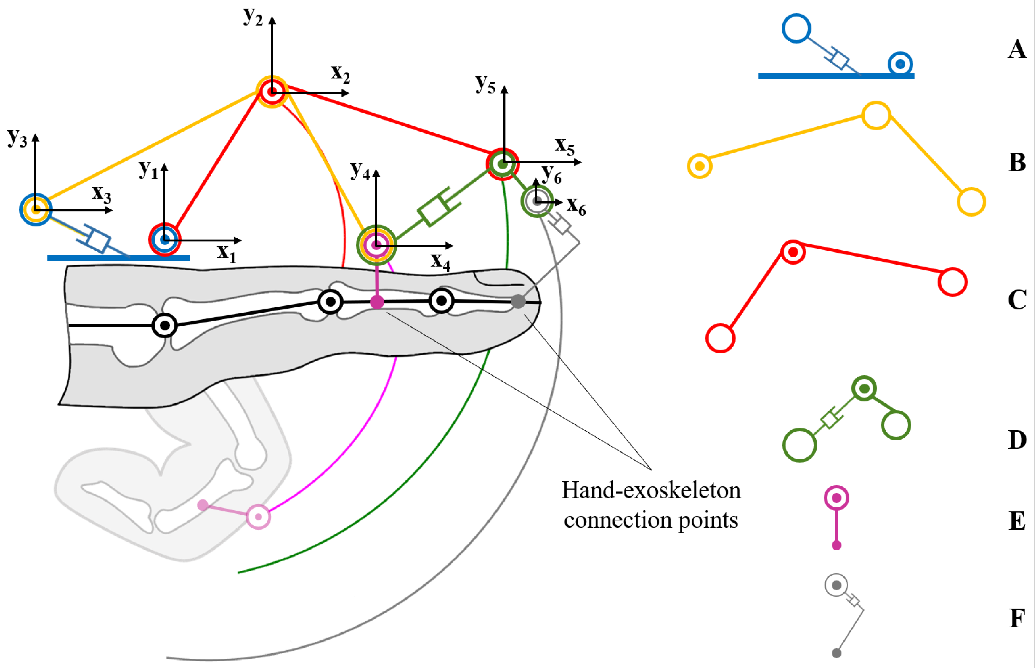
Figure 1 shows the single-DOF kinematic chain exploited to move each long finger: The center of the reference system x 1 y 1 related to the body A is fixed to the hand, roughly right above the MetaCarpoPhalangeal (MCP) joint. The other reference systems x 2 y 2 , x 3 y 3 , x 4 y 4 , x 5 y 5 and x 6 y 6 are integral with the bodies C, B, E, D and F. To simplify the notation each reference frame will also be related to a specific joint following the numerical progression (e.g., joint 1 is related to frame x 1 y 1 , joint 2 to frame x 2 y 2 and so on). Component F is a thimble which has been added in the first version of the presented hand exoskeleton whose presence does not modify the 1-DOF kinematic chain of the device. For this reason, even if the thimble introduces a second connection point with the hand, this will not be considered a proper end-effector and the attention will mainly focus on component E.
The forward kinematics equations of the mechanism can be obtained starting from the revolute constraints, identifying rotational joints, in O x 1 y 1 , O x 2 y 2 , O x 4 y 4 :
0 = 1 p 2 + R 2 1 2 p 1
1 p 2 = 1 p 3 + R 3 1 3 p 2
1 p 4 = 1 p 3 + R 3 1 3 p 4 .
where, referring to Figure 1 and according to the mathematical notations reported in [6], the position of the origin of the i-frame with respect to j-frame has been denoted by the vector j p i = j p i x j p i y T R 2 (the component on z i axis has been omitted as the proposed mechanism acts on a plane) and R i j represents the orientation of i-frame with respect to j-frame, which, in this case, results in a rotation about z i axis through an angle α i .
By analyzing the two cylindrical joints 3 and 5, the constraints equations are:
a 1 1 p 3 x + b 1 1 p 3 y + c 1 = 0
a 2 4 p 5 x + b 2 4 p 5 y + c 2 = 0
where
1 p 5 = 1 p 2 + R 2 1 2 p 5
and
1 p 5 = 1 p 4 + R 4 1 4 p 5 .
In Equations (4) and (5), a 1 , b 1 , c 1 and a 2 , b 2 , c 2 represent the two linear constraints of the mechanism and Equations (6) and (7) have been obtained considering the rotational joint in 5. Finally, even if it does not alter the kinematics of the device, an additional reference system (i.e., x 6 y 6 ) has been considered in the kinematic synthesis.
1 p 6 = 1 p 4 + R 4 1 4 p 6 .
Referring to Equations (1)–(8), the state of the system is represented by the vector
q = 1 p 2 T , 1 p 3 T , 1 p 4 T , 1 p 5 T , 1 p 6 T , α 2 , α 3 , α 4 T R 13
and depends on the control variable α 2 . The unknowns representing the state of the system can be thus calculated as a function of only α 2 by solving Equations (1)–(8). All the interesting points of the mechanism (included in the state vector q ) are in fact completely described as functions of the angle α 2 and of the geometrical parameters S R 16 :
S = [ 2 p 1 T , 3 p 2 T , 2 p 5 T , 3 p 4 T , 4 p 6 T , a 1 , b 1 , c 1 , a 2 , b 2 , c 2 ] T .
All these parameters are completely known because they represent geometric quantities, depending only on the design of the exoskeleton parts. Consequently, it is possible to solve the extended direct kinematic model q ˜ = f ( α 2 , S ) R 12 (see Equation (11)) of the mechanism writing a function of α 2 and S , where q ˜ is the unknown part of the state vector q :
q ˜ = [ 1 p 2 x , 1 p 2 y , 1 p 3 x , 1 p 3 y , α 3 , 1 p 4 x , 1 p 4 y , α 4 , 1 p 5 x , 1 p 5 y , 1 p 6 x , 1 p 6 y ] T = f ( α 2 , S ) .
The closed form resolution of the aforementioned forward kinematic is given hereinafter. Each component of vector q ˜ is highlighted in blue when it is solved in terms of only α 2 and elements of S . Starting from Equation (1), it is possible to obtain Equations (12) and (13):
1 p 2 x ( α 2 ) = - ( c α 2 · 2 p 1 x - s α 2 · 2 p 1 y )
1 p 2 y ( α 2 ) = - c α 2 · 2 p 1 y - s α 2 · 2 p 1 x .
From Equations (2) and (4), the following equations can be written:
1 p 2 x - 1 p 3 x = c α 3 · 3 p 2 x - s α 3 · 3 p 2 y 1 p 2 y - 1 p 3 y = c α 3 · 3 p 2 y + s α 3 · 3 p 2 x a 1 · 1 p 3 x + b 1 · 1 p 3 y + c 1 = 0 .
and solving the system:
1 p 3 y ( α 2 ) = - 1 p 2 x · b 1 a 1 + b 1 · c 1 a 1 2 - 1 p 2 y b 1 a 1 2 + 1 + 1 p 2 x · b 1 a 1 + b 1 · c 1 a 1 2 - 1 p 2 y 2 - b 1 a 1 2 + 1 · H b 1 a 1 2 + 1
1 p 3 x ( α 2 ) = - 1 a 1 · b 1 · 1 p 3 y + c 1
where
H = 1 p 2 x 2 + 1 p 2 y 2 - 3 p 2 x 2 - 3 p 2 y 2 + 2 · 1 p 2 x · b 1 a 1 + c 1 a 1 2 .
and depends only on known values. Now α 3 can be computed as:
α 3 ( α 2 ) = a tan 2 - 1 p 2 x + 1 p 3 x + 3 p 2 x 3 p 2 y · 1 p 2 y - 3 p 2 x 3 p 2 y · 1 p 3 y 3 p 2 y + 3 p 2 x 2 3 p 2 y , 1 p 2 y - s α 3 · 3 p 2 x - 1 p 3 y 3 p 2 y .
At this point, Equations (19) and (20) can be written from Equation (3):
1 p 4 x ( α 2 ) = 1 p 3 x + c α 3 · 3 p 4 x - s α 3 · 3 p 4 y
1 p 4 y ( α 2 ) = 1 p 3 y + c α 3 · 3 p 4 y + s α 3 · 3 p 4 x .
From Equation (6), one can get
1 p 5 x ( α 2 ) = 1 p 2 x + c α 2 · 2 p 5 x - s α 2 · 2 p 5 y
1 p 5 y ( α 2 ) = 1 p 2 y + c α 2 · 2 p 5 y + s α 2 · 2 p 5 x
and from Equations (5) and (7):
1 p 5 x - 1 p 4 x = c α 4 · 4 p 5 x - s α 4 · 4 p 5 y 1 p 5 y - 1 p 4 y = c α 4 · 4 p 5 y + s α 4 · 4 p 5 x a 2 · 4 p 5 x + b 2 · 4 p 5 y + c 2 = 0 .
As in the previous cases, it can be obtained
4 p 5 y ( α 2 ) = - b 2 · c 2 + b 2 · c 2 2 - b 2 2 + a 2 2 · T b 2 2 + a 2 2
4 p 5 x ( α 2 ) = - 1 a 2 · b 2 · 4 p 5 y + c 2
where:
T = - a 2 2 · 1 p 5 x - 1 p 4 x 2 + 1 p 5 y - 1 p 4 y 2 + c 2 2 .
α 4 is now calculated as:
α 4 ( α 2 ) = a t a n 2 - 1 p 4 y + 1 p 5 y - 4 p 5 y 4 p 5 x · 1 p 5 x + 4 p 5 y 4 p 5 x · 1 p 4 x - 4 p 5 x + 4 p 5 y 2 4 p 5 x , 1 p 5 x + s α 4 · 4 p 5 y - 1 p 4 x 4 p 5 x .
Finally, 1 p 6 results:
1 p 6 x ( α 2 ) = 1 p 4 x + c α 4 · 4 p 6 x - s α 4 · 4 p 6 y
1 p 6 y ( α 2 ) = 1 p 4 y + c α 4 · 4 p 6 y + s α 4 · 4 p 6 x
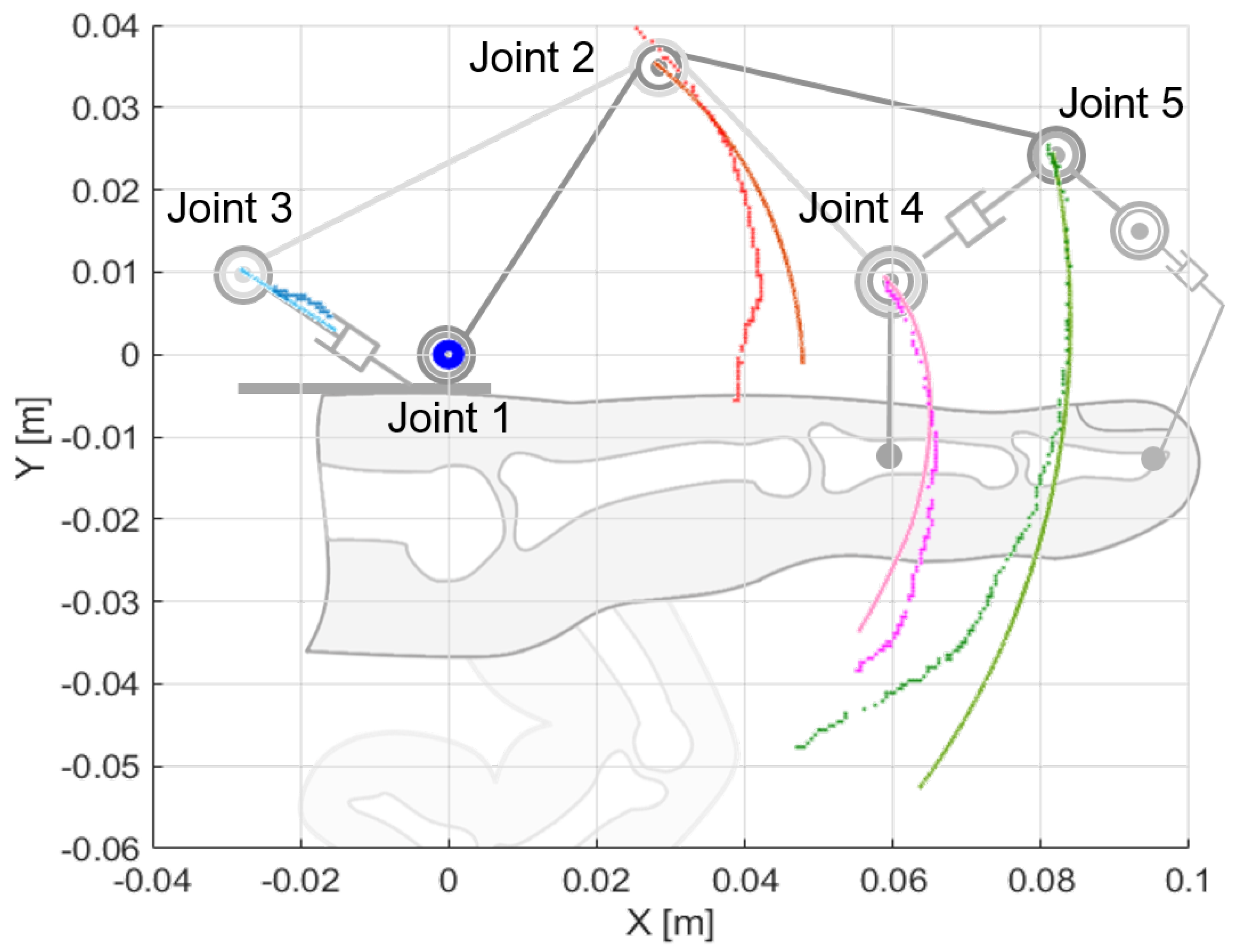
At this point, the motion is completely described and the positions of every joint relative to the 1-frame is given. Figure 1 also shows the trajectories of the finger mechanism joints, providing a qualitative overview of the resulted kinematics of the mechanism when fingers are actuated.

3. First Prototype: Kinematic Validation

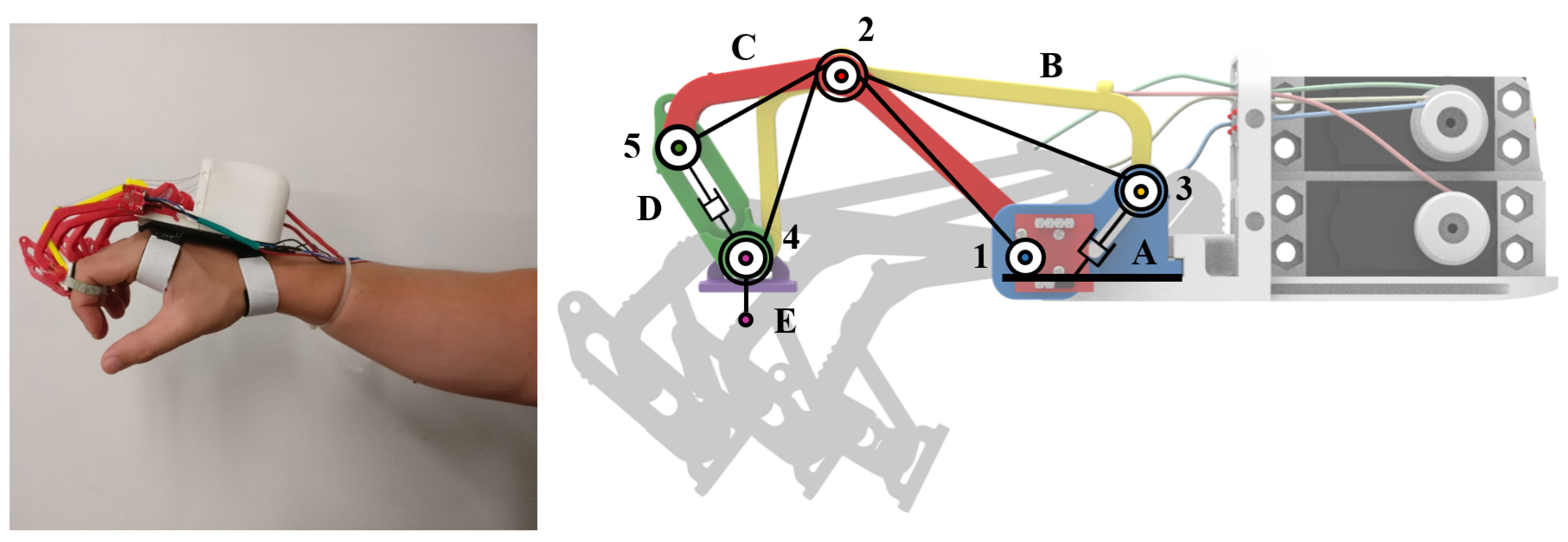
A first version of the hand exoskeleton (shown Figure 2 and detailed in [34,35]) has been designed and manufactured to test the embodiment of the kinematic model proposed in Section 2. A patient affected by SMA was the first user of the device, specifically developed for him.

3.1. Mechanical Design

All the mechanical parts have been 3D-printed using a Dimension Elite by Stratasys in ABS thermoplastic polymer. One of the main advantages of 3D-printing technology is that it allows to manufacture components without considering technological constraints due to the particular production method as well as it may happen using subtracting processes. Then, among different 3D-printable materials, ABS has been chosen because it represents a satisfying trade-off between good mechanical characteristics, lightness, and cheapness.
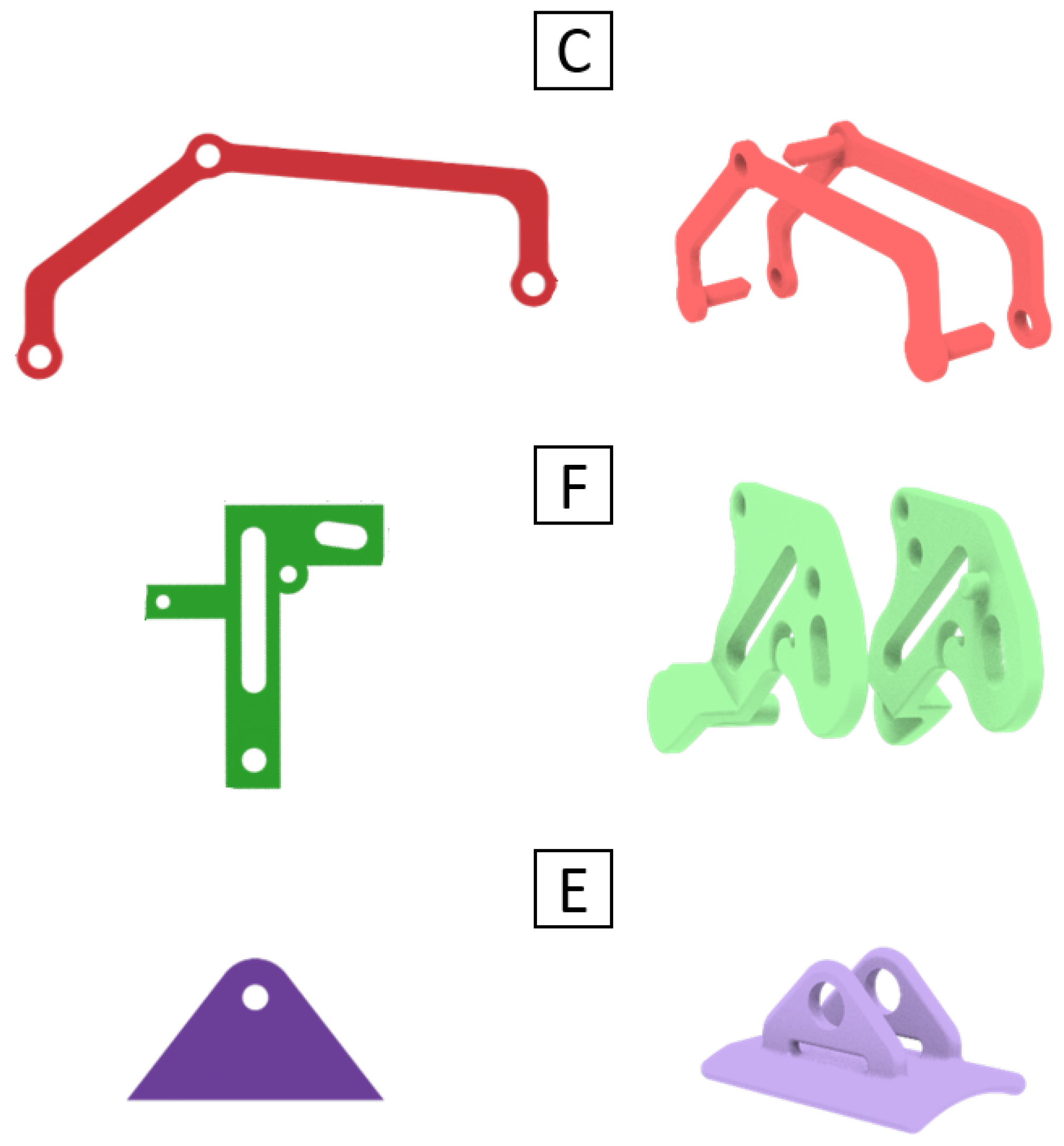
The design process was composed of three sequential phases. Firstly, 2D trajectories of the index finger of the specific user were acquired exploiting open source software Kinovea, https://www.kinovea.org/ (accessed on 26 March 2019). Secondly, an optimization MATLAB-based algorithm [36] minimized the constrained nonlinear multi-variable function describing the kinematics of the mechanism, modifying its geometrical parameters and leading the mechanism kinematics to fit the acquired trajectories. Thirdly, a scaling phase allowed to adapt the kinematic model to each patient’s finger by resizing the geometry of the index finger mechanism accordingly to the dimensions of the other fingers. Then, once the mechanism features was defined, virtual tests exploiting SolidWorks Motion Simulation tools have then been carried out to assess, before the manufacturing of the device, the hand-exoskeleton kinematic coupling and interaction in simple opening and closing gestures. Finally, right before the manufacturing, the mechanical parts have undergone a further reshaping process which has changed their structure, but which has not changed their overall kinematics (as shown in Figure 2, the shapes of the real parts differ from the straight lines of the kinematic model, but the position of the joints has remained unchanged). This later step was required to avoid possible interpenetrations with the hand and, as described in the following lines, for reasons of mounting and loading conditions.
In particular, component C was split in two parts guaranteeing a symmetric load configuration during the use of the exoskeleton and obtaining a more stable solution. Components D was made in two parts as well, allowing them to be assembled together. Component E, which represents the hand-exoskeleton interface, has been designed to wrap only the back side of the finger phalanx not to reduce the sense of touch, while a Velcro held the finger tight achieving a solid connection. To reduce the lateral encumbrances of each mechanism, pins and shafts were directly integrated in the ABS components as lateral rods. All the aforementioned modifications are graphically reported in Figure 3.

3.2. Actuation System and Control Strategy

As visible in Figure 2, both the transmission and the actuation system are placed on the hand backside, as well as the mechanisms are positioned on the fingers, and they do not impede objects handling. The reduction of the total mass, which was one of the main requirements of the device, has led to the choice of high power density actuators to be directly mounted on the back of the hand.
Four Savox SH-0254 servomotors, http://www.savoxusa.com (accessed on 26 March 2019), one per long finger, have been selected for their characteristics: maximum torque of 0.38 Nm and maximum angular speed of 7.69 rad/s at 6.0 V, with a size of 22.8 × 12 × 29.4 mm and weight of 16 g. These motors have been modified to allow for the continuous rotation of the shaft despite the resulting loss of position feedbacks. The four servomotors are in charge of opening the fingers at the same time by pulling cables which have two connection points on each finger mechanism. Closing gesture is, instead, passively allowed releasing the same cables.
The control unit was based on a 6-channels MicroMaestro control board, https://www.pololu.com (accessed 26 March 2019) which has been chosen for its cheapness, its lightness (only 5 g), its small dimensions (21 × 30 mm ) and, above all, because its six channel matched the number of external devices that had to be connected to the board: the aforementioned four servomotors and two buttons, one for opening and one for closure triggering action. The control unit and the actuators were powered by a compact 4-cell Lithium battery (at 6.0 V), which was placed in an elastic band on the arm of the user, provided with a safety switch close to the buttons case, mounted instead on the forearm.
Regarding the control strategy, the system was controlled by a simple script, stored and running directly on the MicroMaestro chip-set. The code had to continuously check for one of the two buttons to be pushed and held down and then react by sending the corresponding command to the actuators. This version did not include sensors for fingers position feedback and the bounds of the exoskeleton range of motion were manually managed by the user (keeping pushed or releasing the buttons) in order not to overcome his anatomical limits. Even thought there was one motor per finger, the possibility to move each of them independently from the others has not been considered for simplicity and all the long fingers were moved together.

3.3. Testing

The whole mechatronic system described in the previous sections has then been assembled and tested to evaluate the manufacturability of the adopted solution (see Figure 2). The single DOF mechanism, the one visible in Figure 1, consists in a closed kinematic chain mechanism capable of applying a defined roto-translation motion to the middle point of the intermediate phalanx. Again, Kinovea software has been employed in this testing phase. The exoskeleton has been worn by the user who has been told to perform some opening and closing gestures. Colored markers have been placed on the mechanism joints and their trajectories have been extracted from the images. Finally, the acquired trajectories has been compared to the kinematic model ones. The comparison between real data and simulated trajectories are presented in Figure 4 only for the index finger mechanism. The same considerations can be adopted for all other long fingers.
Despite the fact that the comparison of the trajectories has given encouraging results—in particular with regard to the joint 2, which is the main point of interaction between the exoskeleton and the finger—tests conducted on this first version highlighted several flaws which negatively impacted on its usability.
  • The patient pointed out that being forced by the exoskeleton to move the fingers only on the flex/extension plane (this prototype did not allow for the ab/adduction movement of the MCP joint) resulted in an extremely annoying feeling.
  • As well as the comfort, also the intuitiveness of control was very low: the patient had, in fact, to use both hand to move just one because of the buttons-driven actuation system.
  • The lack of a proper position feedback over the flex/extension angle of the finger did not allow for a safe automatic control over the Range of Motion (ROM).
  • The solution provided by the exploited optimization algorithm was, by the nature of the algorithm itself, strongly dependable on the choice of the initial state, which was arbitrarily made accordingly to the imposed geometric constraints. This process hence resulted in being low-adaptable to different hand sizes because of the necessity of proper setting the initial state of the algorithm every time, and it also offered no guarantees of finding a real optimum solution.
The tested device hence resulted in being still far from a clinical application and many improvements had to be made to move towards that direction.

4. Second Prototype: Ergonomics and Adaptability Improvements

Starting from the weaknesses of the exoskeleton version discussed in Section 3 and considering that the adaptability and the ease of wearing requirements must be, not only kept, but also improved, a second prototype of the hand exoskeleton has been developed and printed. In particular, thanks to the experience gained during the testing phase several modifications have been made to produce a more comfortable and wearable system, and develop a new design procedure easier to adapt to different users. The high wearability of a system is hence endorsed by its transparency with respect to the hand natural kinematics, rising from a device which is not felt as a constraint, but whose use actually results straightforwardly intuitive. Both the optimization strategy, leading to a mechanism which replicates at best the fingers gestures, and the revamping design, heading to a lighter solution, contribute to a system better accepted by the end user.

4.1. Mechanical Design

The optimization algorithm, in charge of modifying the geometry of the device accordingly to the fingers trajectories has been replaced: a Nelder-Mead based optimization algorithm, used to solve non convex, non linear constrained problems, has been applied achieving a straightforward adaptability to several users [37]. Taking acquisition data (collected exploiting a BTS SMART-Suite MoCap System by BTS Bioengineering (BTS Bioengineering, Garbagnate Milanese (MI), Italy)) and the kinematics of the mechanism as inputs, the implemented algorithm provides a customized geometry specific for each patient.
A CAD model has then been developed by using parametric dimensions to make the whole procedure automatic. This choice leads to two important consequences. Firstly, the position of each joint results directly connected to the outputs of the optimization routine without requiring manual intervention. In addition, as well as tested with the first prototype, a parametric CAD model enable wearing simulations. By replicating virtual opening and closing gestures with the device worn by the user, the exoskeleton kinematics and its coupling with each finger can be checked and assessed. The ABS prototype is then print out exploiting the Fused Deposition Modeling (FDM) additive manufacturing technique.
Even though the overall kinematics of the finger mechanism has not been changed with respect to the first prototype, the mechanical architecture of the exoskeleton has been subjected to important modifications. The thimble wrapping the finger tip has been eliminated leaving only one contact point between each finger and the device. By removing this component, the driving purpose of the finger mechanism has been kept but the uncomfortable feeling of having the whole finger constraint to a rigid system has been avoid. This choice also leaves the touching feeling while grabbing objects. A passive DOF has been added upstream joint 1 (refer to Figure 1) to follow finger abduction and adduction motions during hand opening and closing. This solution also improves the auto-alignment between finger and mechanism joints.

4.2. Actuation System and Control Strategy

To get closer to the needs come out during the tests on the previous prototype, this new “release” of the hand exoskeleton presents only two servomotors Hitec HS-5495BH (http://hitecrcd.com/products/servos/sport-servos/digital-sport-servos/hs-5495bh-hv-digital-karbonite-gear-sport-servo/product): one of them guides the index finger flexion/extension, the other one is in charge of moving the other three long fingers. In addition to reducing the overall weight and encumbrance of the system, reducing the number of actuators overcome an issue that has immediately occurred the high difficulty to prevent the four motors from acquiring more and more relative phase shift with the prolonged use.
Two motors, one the other side, require an important change in the transmission system: because of the different sizes of each finger mechanisms (due to, in turn, the dissimilar dimensions of the fingers), closing and opening velocity for each finger must be different one to the others. To overcome this issue, the pulley spliced to the output shaft of the actuator in charge of moving three long fingers has been thought with three different diameters. That introduced a set gear ratio and, since the wires connected to the three fingers mechanisms winds pulley with different diameters, middle, ring and small finger mechanisms are moved at the same time with the same motor but each one at its own suitable speed. The overall weight of this new prototype resulted in 242 g. Regarding the characteristics of the new actuators, they present a maximum torque of 0.735 Nm at 7.4 V with a size of 39.8 × 19.8 × 38.0 mm and a weight of 44.5 g. The maximum angular speed is 66.67 rad/s at 7.4 V.
Also the control system has been developed aiming to the same goal headed to during the mechanical design: the total costs, complexity and weight of the system must be kept as low as possible. In this framework, Arduino Nano represented a simple, cheap, but performing solution. Two magnetic encoders (15-bit resolution) are spliced on joint 1 of the finger mechanisms (Figure 5). Since one servomotor actuates the index and the other one the other three long fingers, in order to guarantee a suitable control of the grasping, only two encoders are needed: one placed on the index and one on the little finger. They measure the value of the angle α 2 , which identifies pose of the mechanism and, consequently, of the finger fixed to it.
The control strategy is characterized by two main control loops that have been added to safely stop the motion of the exoskeleton once the ROM limits are reached (namely maximum opening and closure), and to check if an object is grabbed. While the permanence within the ROM boundaries is easily checked by means of the direct measurement from the encoders, the grabbing of an object is recognized and detected by the evaluation of the length of the unrolled cable twice. The first evaluation is made by the kinematic equations of the mechanism and the second one exploiting the motors speed and the pulleys radius. Comparing the differential measurement to a fixed threshold (set at 10 mm, which is roughly the length of a quarter of the motor pulley circumference) allows to understand if the actuation system is still releasing cable while the hand is not further moving. This means that an object is likely grasped. In both cases each motor stops while holding its current angular position.

Testing

In this the results obtained related to the validation and testing of the second prototype will be presented and discussed. A real ABS prototype has been hence 3D-printed to test the manufacturability of the kinematic architecture and assess the goodness of the optimization strategy for different users. The tests have been carried out at the Don Carlo Gnocchi Foundation Rehabilitation Center in Florence, Italy, making use of the MoCap system used also to evaluate the motion of the hand alone; the cameras configuration exploited to validate the second prototype is the same used during the motion capture of the hand.
The right index finger motion of the 13 subjects enrolled to validate the performance of the optimization procedure has been assessed through a MoCap analysis during three consecutive flexion/extension movements. Taking the aforementioned trajectories as reference, the proposed optimization process has been carried out over the 13 healthy subjects and the results are reported in Table 1.
The results reported in Table 1 allowed to verify and check the reliability of the optimization algorithm when different hand exoskeletons have to be adapted to hands characterized by different dimensions. The average of the maximum calculated errors (this measurement provides a quantitative value of the difference—maximum distance—between the trajectory tracked by the user’s finger and the one generated by the finger mechanism of hand exoskeleton) was 3.16 mm (standard deviation 1.47 mm). That proves the goodness of the implemented optimization strategy in adapting the apriori defined oneDOF kinematic chain to the user’s anatomy.
These new tests have shown promising results with regard to the portability of the device. With the addition of the passive DOF on the ab/adduction movement of the MCP joint, the exoskeleton is considerably more compliant with the hand movements and can be worn longer without feeling as uncomfortable as before. Moreover, the automatic control over the ROM reliably prevents the exoskeleton to move the fingers towards unnatural or painful positions, liberating the user from the fear of hurting himself if not enough attention was paid. The result achieved with new optimization strategy of the geometry of the finger mechanism can be considered even more important though. In fact, this new process allowed the mechanism to be quickly adapted to different users, paving the way to future experimental campaigns on multiple patients. However, the buttons-triggered actuation still remained an open up point to be further investigated.

5. Third Prototype: Intuitive Control

This current version of the exoskeleton (Figure 6) is represented by a fully portable, wearable and highly customizable device that can be used both as an assistive hand exoskeleton and as a rehabilitative one. Both mechatronic design and control system are developed basing on the patients needs in order to satisfy users’ daily requirements increasing their social interaction capabilities.

5.1. Mechanical Design

The mechanics of this last exoskeleton has been revamped to achieve a more lightweight solution improving its wearability without influencing the obtained results in terms of accuracy while replicating hand gestures. The new system is actuated by a single servomotor and a specific cable driven transmission system has been developed to open all the four long fingers together at the same time. Different mechanisms velocities are obtained thanks to different pulleys diameters, which are calculated depending on users’ fingers dimensions, and coupled with the same common shaft which is moved by the motor through a belt transmission. The mechanism kinematic architecture has been further modified by eliminating component D of Figure 1. Thickness of components C and B has thus been increased to bear the heavier load cycle these components are now subjected to during functioning.

5.2. Actuation System and Control Strategy

The first important difference with respect to the previous systems is that, as reported above, another motor has been removed adopting a single-motor actuation system. Even though the motor has not been changed, the exploitation of just one actuator has brought with it some advantages: the total weight of the system has been remarkably reduced and the control code has resulted in being computationally lighter, not having to manage the coordination between motors. Nevertheless, the main difference of this prototype lies in the triggering system. Tests conducted on the second version of the prototype have hence stressed the importance for the user of being able to use both hands independently, pushing the buttons-based triggering action to be replaced with something which could allow for an autonomous control of each hand. Following the most recent research trends in literature (e.g., [38,39]), a specific EMG-based control architecture has been developed letting the user the total control of the exoskeleton actuation without being forced to use the other hand (as it happened with the first and the second prototypes).
Accordingly to the guidelines of the research work, also the electronics of the system has been reduced to the minimum necessary. Two MyoWare Muscle Sensors (AT-04-001) by Advancer Technologies https://learn.sparkfun.com/tutorials/myoware-muscle-sensor-kit have been chosen for collecting EMG signals from specific forearm muscles, i.e., flexor digitorum superficialis and extensor digitorum superficialis. These sensors, small (20.8 × 52.3 mm) and low-powered, measure the electrical activity of a muscle, outputting either raw EMG signals or enveloped EMG signals, which are amplified, rectified and integrated.
The proposed control strategy, presented in [40] and detailed in [41], can be split in two main parts, which are sequentially executed every 33 ms (i.e., at 30 Hz). The first one is in charge of classifying user’s intentions from the muscular activity measurements, the second one instead manages the corresponding actuation of the system. Within the second part of the code, an outer control loop checks if the system overcomes a fixed ROM and an inner control loop, which is only active during hand closing, is meant to check if an object is grasped. by evaluating the closing velocity of the index finger. when it drops below a fixed threshold while the motor is still running, it is reasonable to think that the hand has encountered an object or an obstacle. Real-time information about the position and the velocity of the index finger is collected by means of the magnetic encoder mounted on the exoskeleton in correspondence of the MCP joint of the finger.
Since the human hand can perform lots of different gestures and the corresponding muscles are very close to each other, a precise classification of every user intention usually requires the use of workstations, which is definitely far away from the idea of cheapness and wearability this project is based on. Hand opening, hand closing and hand resting have then been considered as the only possible user’s intentions to be classified, as they represent the basic hand motions for the ADLs.
The classification phase is carried out by means of an algorithm called “Point-in-Polygon algorithm”. This algorithm works on the base of a ray-casting to the right. It takes as inputs the number of the polygon vertices, their coordinates and the coordinates of a test point; each iteration of the loop, the line (ray) drawn (cast) rightwards from the test point is checked against the polygon perimeter and the number of times this line intersect a different edge is counted; if the number of crosses is an odd number of times, then the point is inside, if an even number, the point is outside. This classifier is tuned during a preliminary training phase through a custom Qt Graphical User Interface (GUI) developed by the authors. It is a user-friendly tool which allows for collecting EMG signals and for displaying them on a 2D Cartesian plane, whose axis report respectively data from the first and the second sensor. Once the EMG data has been collected for all the three aforementioned gestures, it is possible to manually draw the geometric figures which delimit the data corresponding to the same gesture. The correct choice of the parameters of the polygons (e.g., vertices, shape, size) represent a crucial point of the classification phase which is supposed to be performed basing on patient’s needs to improve the accuracy and the rejection of disturbs.

5.3. Testing

At the time of writing, the version of the exoskeleton presented in this section is at the heart of an application for an experimental campaign protocol that has not been submitted to an Ethical Committee yet. Only a few preliminary tests have been conducted and their results can be found in [41]. Although quantitative data about the proposed control strategy still lack, it can be asserted that it, surely, represent a step towards intuitiveness and a step forward for the prototype itself.

6. Conclusions

This work collects the results of the research activity on wearable robotics carried out at the Mechatronics and Dynamic Modeling Laboratory of the Department of Industrial Engineering of the University of Florence during the years 2015–2018. The activity focused on the study of design strategies for hand exoskeletons, starting from the analysis of stateoftheart solutions and leading to the development of new robotic devices. Hand exoskeletons mechanical design constituted the main subject of the research, motivated by the issue that people who have lost or injured hand skills are deeply compromised in the possibility of an independent and healthy life with a sensitive reduction in the quality of their lives themselves. Since robotic devices, such as hand exoskeletons, may represent an effective solution for the patient affected by hand opening disabilities, or other mobility impairments, the focus was particularly given to the development of a robotic solution provider of an aid during prolonged and highintensity rehabilitation treatments. Such systems also contribute to reduce costs and burden for the therapists, as long as being an effective aid in the execution of ADLs.
The overall research activity aimed not only to present the design of the hand exoskeletons developed by the University of Florence, but also, and actually mainly, to propose new usercentered and patientbased strategies which can be adopted in the production of wearable systems. The optimizationbased scaling strategy (which, starting from the users’ own gestures, leads to a tailormade device) along with the mechanical choices (which guarantee the outline of a lightweight and compact overall system) center the enduser on the design process and the proposed wearable systems are fully designed around him. In all the presented hand exoskeleton prototypes, the system kinematics plays the main role for the design of a tool as much wearable as possible, which guarantees a comfortable feeling even during the prolonged use.
Starting from the same kinematic architecture, three different hand exoskeletons have been developed heading for four features mandatory for the actual use of the device: the comfortable feeling for the user, the adaptability of the kinematic chain of the finger mechanism to the patient’s hand, the safe use of the device, and the userfriendly activation system and control of the exoskeleton. Table 2 summarizes the main results achieved in the design of each prototype.
However, achieving the aforementioned feature was particularly difficult when the constraints of the single DOF had to be maintained. The proposed solution resulted in a tight (due the 1 DOF per finger, cabledriven, singlemotor system) device capable of precisely replicating the hand gestures. The satisfying results highlighted the goodness of the derived solutions, which may constitute a suitable alternative to existing hand exoskeletons. Nonetheless, there is still room for improvement: for instance, clinical trials exploiting the reached device may allow for the assessment of the impact the hand exoskeleton would have during real rehabilitation sessions. A testing phase, employing a real actuation system, represents the first opened up point, which could lead to the necessity of improving the mechanical architecture of the whole exoskeleton in order to increase its usability and efficacy. Also the employment of different materials, whose structural features may benefit the robustness of the device, inspires the possibility for further investigations [42,43]. The last, but not least, important issue which is worth being explored in the near future is the assessment of the pose of the hand depending on the task it is required to accomplish. As reported in [44], the control of hand posture involves a few postural synergies leading to reduce the number of degrees measured by the hands anatomy and independently on the grip taxonomies. In this sense, considering the synergies occurred in some specific gestures [45] in the motion analysis assessment (Section 4.1) would allow the exoskeleton to guide the fingers with more effectiveness.
All these issues, whose resolution constitutes a natural continuation of the research activity carried out thus far, will be subjected to further investigation in the very near future.

Author Contributions

Design & Development, N.S. and M.B. (Matteo Bianchi); Supervision A.R. and Y.V.; Validation, F.V. and M.B. (Massimo Bianchini); Conceptualization, L.G. and B.A.

Funding

This work has been supported by Don Carlo Gnocchi Foundation (Italy) and by the HOLD project (Hand exoskeleton system, for rehabilitation and activities Of daily Living, specifically Designed on the patient anatomy), funded by the University of Florence.

Conflicts of Interest

The authors declare no conflict of interest.

References

  1. Heller, A.; Wade, D.; Wood, V.; Sunderland, A.; Hewer, R.; Ward, E. Arm function after stroke: Measurement and recovery over the first three months. J. Neurol. Neurosurg. Psychiatry 1987, 131, 714–719. [Google Scholar] [CrossRef] [PubMed]
  2. Wade, D.; Langton-Hewer, R.; Wood, V.; Skilbeck, C.; Ismail, H. The hemiplegic arm after stroke: Measurement and recovery. J. Neurol. Neurosurg. Psychiatry 1983, 46, 521–524. [Google Scholar] [CrossRef]
  3. Sunderland, A.; Tinson, D.; Bradley, L.; Hewer, R. Arm function after stroke. An evaluation of grip strength as a measure of recovery and a prognostic indicator. J. Neurol. Neurosurg. Psychiatry 1989, 52, 1267–1272. [Google Scholar] [CrossRef] [PubMed]
  4. Nakayama, H.; Jørgensen, H.; Raaschou, H.; Olsen, T. Recovery of upper extremity function in stroke patients: The Copenhagen Stroke Study. Arch. Phys. Med. Rehabil. 1994, 75, 394–398. [Google Scholar] [CrossRef]
  5. World Health Organization. WHO Global Disability Action Plan 2014–2021: Better Health for All People with Disability; Technical Report; World Health Organization: Geneva, Switzerland, 2014. [Google Scholar]
  6. Bruno, S.; Oussama, K. Springer Handbook of Robotics; Springer: Berlin, Germany, 2016. [Google Scholar]
  7. Heo, P.; Gu, G.M.; Lee, S. Current hand exoskeleton technologies for rehabilitation and assistive engineering. Int. J. Precis. Eng. Manuf. 2012, 13, 807–824. [Google Scholar] [CrossRef]
  8. Troncossi, M.; Mozaffari-Foumashi, M.; Parenti-Castelli, V. An Original Classification of Rehabilitation Hand Exoskeletons. J. Robot. Mech. Eng. Res. 2016, 1, 17–29. [Google Scholar] [CrossRef]
  9. Bos, R.A.; Haarman, C.J.; Stortelder, T.; Nizamis, K.; Herder, J.L.; Stienen, A.H.; Plettenburg, D.H. A structured overview of trends and technologies used in dynamic hand orthoses. J. NeuroEng. Rehabil. 2016, 13, 62. [Google Scholar] [CrossRef] [PubMed]
  10. Harwin, W.S.; Patton, J.L.; Edgerton, V.R. Challenges and opportunities for robot-mediated neurorehabilitation. Proc. IEEE 2006, 94, 1717–1726. [Google Scholar] [CrossRef]
  11. Rosenstein, L.; Ridgel, A.L.; Thota, A.; Samame, B.; Alberts, J.L. Effects of combined robotic therapy and repetitive-task practice on upper-extremity function in a patient with chronic stroke. Am. J. Occup. Ther. 2008, 1, 28–35. [Google Scholar] [CrossRef]
  12. Martinez, L.; Olaloye, O.; Talarico, M.; Shah, S.; Arends, R.; BuSha, B. A power-assisted exoskeleton optimized for pinching and grasping motions. In Proceedings of the 2010 Northeast Bioengineering Conference, New York, NY, USA, 26–28 March 2010; pp. 1–2. [Google Scholar] [CrossRef]
  13. Moromugi, S.; Koujina, Y.; Ariki, S.; Okamoto, A.; Tanaka, T.; Feng, M.Q.; Ishimatsu, T. Muscle stiffness sensor to control an assistance device for the disabled. Artif. Life Robot. 2004, 8, 42–45. [Google Scholar] [CrossRef]
  14. Iqbal, J.; Tsagarakis, N.; Fiorilla, A.; Caldwell, D. A portable rehabilitation device for the hand. In Proceedings of the International Conference of the IEEE Engineering in Medicine and Biology, Buenos Aires, Argentina, 1–4 September 2010; pp. 3694–3697. [Google Scholar] [CrossRef]
  15. Jones, C.; Wang, F.; Osswald, C.; Kang, X.; Sarkar, N.; Kamper, D. Control and kinematic performance analysis of an Actuated Finger Exoskeleton for hand rehabilitation following stroke. In Proceedings of the International Conference on Biomedical Robotics and Biomechatronics (BioRob), Tokyo, Japan, 26–29 September 2010; pp. 282–287. [Google Scholar] [CrossRef]
  16. Li, J.; Zheng, R.; Zhang, Y.; Yao, J. iHandRehab: An interactive hand exoskeleton for active and passive rehabilitation. In Proceedings of the International Conference on Rehabilitation Robotics (ICORR), Tokyo, Japan, 26–29 September 2010; pp. 1–6. [Google Scholar] [CrossRef]
  17. Hasegawa, Y.; Mikami, Y.; Watanabe, K.; Sankai, Y. Five-fingered assistive hand with mechanical compliance of human finger. In Proceedings of the International Conference on Robotics and Automation (ICRA), Pasadena, CA, USA, 19–23 May 2008; pp. 718–724. [Google Scholar] [CrossRef]
  18. Schabowsky, C.; Godfrey, S.; Holley, R.; Lum, P. Development and pilot testing of HEXORR: Hand EXOskeleton Rehabilitation Robot. J. Neuroeng. Rehabil. 2010. [Google Scholar] [CrossRef] [PubMed]
  19. Wege, A.; Kondak, K.; Hommel, G. Mechanical design and motion control of a hand exoskeleton for rehabilitation. In Proceedings of the International Conference on Mechatronics and Automation, Niagara Falls, ON, Canada, 20 July–1 August 2005; pp. 155–519. [Google Scholar] [CrossRef]
  20. Chiri, A.; Vitiello, N.; Giovacchini, F.; Roccella, S.; Vecchi, F.; Carrozza, M. Mechatronic Design and Characterization of the Index Finger Module of a Hand Exoskeleton for Post-Stroke Rehabilitation. IEEE/ASME Trans. Mech. 2012, 17, 884–894. [Google Scholar] [CrossRef]
  21. Wege, A.; Hommel, G. Development and control of a hand exoskeleton for rehabilitation of hand injuries. In Proceedings of the International Conference on Intelligent Robots and Systems (IROS 2005), Edmonton, AB, Canada, 2–6 August 2005; pp. 3046–3051. [Google Scholar] [CrossRef]
  22. Takahashi, C.; Der-Yeghiaian, L.; Le, V.; Motiwala, R.; Cramer, S. Robot-based hand motor therapy after stroke. Brain 2008, 131, 425–437. [Google Scholar] [CrossRef] [PubMed]
  23. Mulas, M.; Folgheraiter, M.; Gini, G. An EMG-controlled exoskeleton for hand rehabilitation. In Proceedings of the International Conference on Rehabilitation Robotics, Bellevue, WA, USA, 20–24 June 2013; pp. 371–374. [Google Scholar] [CrossRef]
  24. Rotella, M.F.; Reuther, K.; Hofmann, C.; Hage, E.; BuSha, B. An orthotic hand-assistive exoskeleton for actuated pinch and grasp. In Proceedings of the Northeast Bioengineering Conference, Cambridge, MA, USA, 3–5 April 2009; pp. 1–2. [Google Scholar] [CrossRef]
  25. Brokaw, E.; Black, I.; Holley, R.; Lum, P. Hand Spring Operated Movement Enhancer (HandSOME): A Portable, Passive Hand Exoskeleton for Stroke Rehabilitation. Trans. Neural Syst. Rehabil. Eng. 2011, 19, 391–399. [Google Scholar] [CrossRef] [PubMed]
  26. Stilli, A.; Cremoni, A.; Bianchi, M.; Ridolfi, A.; Gerii, F.; Vannetti, F.; Wurdemann, H.A.; Allotta, B.; Althoefer, K. AirExGlove—A novel pneumatic exoskeleton glove for adaptive hand rehabilitation in post-stroke patients. In Proceedings of the 2018 IEEE International Conference on Soft Robotics, Livorno, Italy, 24–28 April 2018; pp. 579–584. [Google Scholar] [CrossRef]
  27. Yap, H.; Nasrallah, F.; Lim, J.; Low, F.; Goh, J.; Yeow, R. MRC-glove: A fMRI compatible soft robotic glove for hand rehabilitation application. In Proceedings of the International Conference on Rehabilitation Robotics, Singapore, 11–14 August 2015; pp. 735–740. [Google Scholar] [CrossRef]
  28. Polygerinos, P.; Wang, Z.; Galloway, K.; Wood, R.; Walsh, C.J. Soft robotic glove for combined assistance and at-home rehabilitation. Robot. Auton. Syst. 2015, 73, 135–143. [Google Scholar] [CrossRef]
  29. Deimel, R.; Brock, O. A novel type of compliant and underactuated robotic hand for dexterous grasping. Int. J. Robot. Res. 2016, 35, 161–185. [Google Scholar] [CrossRef]
  30. Delph, M.A.; Fischer, S.; Gauthier, P.; Luna, C.; Clancy, E.; Fischer, G. A soft robotic exomusculature glove with integrated sEMG sensing for hand rehabilitation. In Proceedings of the International Conference on Rehabilitation Robotics, Bellevue, WA, USA, 20–24 June 2013. [Google Scholar] [CrossRef]
  31. Tong, K.; Ho, S.; Pang, P.; Hu, X.; Tam, W.; Fung, K.; Wei, X.; Chen, P.; Chen, M. An intention driven hand functions task training robotic system. In Proceedings of the International Conference of the IEEE Engineering in Medicine and Biology, Buenos Aires, Argentina, 31 August–4 September 2010. [Google Scholar]
  32. Iqbal, J.; Khelifa, B. Stroke rehabilitation using exoskeleton-based robotic exercisers: Mini Review. Biomed. Res. 2015, 26, 197–201. [Google Scholar]
  33. Lucas, L.; DiCicco, M.; Matsuoka, Y. An EMG-Controlled Hand Exoskeleton for Natural Pinching. J. Robot. Mech. 2004, 16, 1–7. [Google Scholar] [CrossRef]
  34. Conti, R.; Meli, E.; Ridolfi, A.; Bianchi, M.; Governi, L.; Volpe, Y.; Allotta, B. Kinematic synthesis and testing of a new portable hand exoskeleton. Meccanica 2017. [Google Scholar] [CrossRef]
  35. Allotta, B.; Conti, R.; Governi, L.; Meli, E.; Ridolfi, A.; Volpe, Y. Development and experimental testing of a portable hand exoskeleton. In Proceedings of the 2015 IEEE/RSJ International Conference on Intelligent Robots and Systems, Hamburg, Germany, 28 September–2 October 2015; pp. 5339–5344. [Google Scholar] [CrossRef]
  36. Byrd, R.H.; Gilbert, J.C.; Nocedal, J. A trust region method based on interior point techniques for nonlinear programming. Math. Program. 2000, 89, 149–185. [Google Scholar] [CrossRef]
  37. Bianchi, M.; Fanelli, F.; Giordani, L.; Ridolfi, A.; Vannetti, F.; Allotta, B. An automatic scaling procedure for a wearable and portable hand exoskeleton. In Proceedings of the 2016 IEEE 2nd International Forum on Research and Technologies for Society and Industry Leveraging a Better Tomorrow, Bologna, Italy, 7–9 September 2016; pp. 1–5. [Google Scholar] [CrossRef]
  38. Lobo-Prat, J.; Kooren, P.N.; Stienen, A.H.; Herder, J.L.; Koopman, B.F.; Veltink, P.H. Non-invasive control interfaces forintention detection in active movement-assistive devices. J. NeuroEng. Rehabil. 2014, 11, 168. [Google Scholar] [CrossRef] [PubMed]
  39. Adewuyi, A.A.; Hargrove, L.J.; Kuiken, T.A. Evaluating EMG Feature and Classifier Selection for Application to Partial-Hand Prosthesis Control. Front. Neurorobot. 2016, 10, 15. [Google Scholar] [CrossRef] [PubMed]
  40. Secciani, N.; Bianchi, M.; Ridolfi, A.; Vannetti, F.; Allotta, B. Assessment of a Hand Exoskeleton Control Strategy Based on User’s Intentions Classification Starting from Surface EMG Signals. In Wearable Robotics: Challenges and Trends; Carrozza, M.C., Micera, S., Pons, J.L., Eds.; Springer International Publishing: Cham, Switzerland, 2019; pp. 40–444. [Google Scholar]
  41. Secciani, N.; Bianchi, M.; Meli, E.; Volpe, Y.; Ridolfi, A. A novel application of a surface ElectroMyoGraphy-based control strategy for a hand exoskeleton system: A single-case study. Int. J. Adv. Robot. Syst. 2019, 16. [Google Scholar] [CrossRef]
  42. Bianchi, M.; Buonamici, F.; Furferi, R.; Vanni, N. Design and Optimization of a Flexion/Extension Mechanism for a Hand Exoskeleton System. In Proceedings of the ASME 2016 International Design Engineering Technical Conferences and Computers and Information in Engineering Conference, Charlotte, NC, USA, 21–24 August 2016. [Google Scholar]
  43. Bianchi, M.; Cempini, M.; Conti, R.; Meli, E.; Ridolfi, A.; Vitiello, N.; Allotta, B. Design of a Series Elastic Transmission for hand exoskeletons. Mechatronics 2018, 51, 8–18. [Google Scholar] [CrossRef]
  44. Santello, M.; Flanders, M.; Soechting, J. Postural hand synergies for tool use. J. Neurosci. 1998, 18, 10105–10115. [Google Scholar] [CrossRef] [PubMed]
  45. Santello, M.; Bianchi, M.; Gabiccini, M.; Ricciardi, E.; Salvietti, G.; Prattichizzo, D.; Ernst, M.; Moscatelli, A.; Jörntell, H.; Kappers, A.M.; et al. Hand synergies: Integration of robotics and neuroscience for understanding the control of biological and artificial hands. Phys. Life Rev. 2016, 17, 1–23. [Google Scholar] [CrossRef] [PubMed]
Sample Availability: Prototypes of the presented exoskeletons are available from the authors.
Figure 1. The figure shows the kinematic chain of the finger mechanism exploited in the presented work. While component A is integral with the back of the hand, the other parts are all mobile and their pose is uniquely identified once known the joint coordinate of joint 1.
Machines 07 00022 g001
Figure 2. The figure shows, on the left, the first version of the hand exoskeleton prototype worn by the patient and, on the right, the corresponding kinematic chain and Computer Aided Manufacturing (CAD) model. Colors and names (capital letters) of the components, and joints enumeration are reported as introduced in Section 2.
Machines 07 00022 g002
Figure 3. The figure shows the adaptation of components C, F, and E.
Machines 07 00022 g003
Figure 4. The figure shows the comparison between the trajectories of the joints of the exoskeleton generated by the kinematic model (solid lines) and the real ones (dashed lines) for the index finger.
Machines 07 00022 g004
Figure 5. The figure shows, on the left, the second version of the exoskeleton system worn by a healthy subject and, on the right, the corresponding kinematic chain and CAD model. Colors and names (capital letters) of the components, and joints enumeration are reported as introduced in Section 2.
Machines 07 00022 g005
Figure 6. The figure shows, on the left, the final and current version of the exoskeleton prototype developed by the DIEF worn by a healthy subject and, on the right, the corresponding kinematic chain and CAD model. Colors and names (capital letters) of the components, and joints enumeration are reported as introduced in Section 2.
Machines 07 00022 g006
Table 1. Length and width of the hand, maximum, average and standard deviation (Std Dev) of the error between the desired and the real trajectory for the index finger, and maximum, average and standard percentage error expressed with respect to the subjects’ finger length.
Dimensions [mm 2 ]Error [mm]Error/Finger Extension [%]
Length × WidthMaximumAverageStd DevMaximumAverageStd Dev
200 × 944.962.661.184.52.41.1
165 × 823.722.291.134.22.61.3
191 × 784.823.151.304.73.11.3
192 × 845.593.681.705.53.61.7
189 × 955.923.831.635.93.81.6
192 × 913.052.050.813.02.00.8
197 × 883.452.101.213.32.01.1
193 × 896.304.121.406.34.11.4
187 × 810.900.530.310.90.50.3
150 × 754.762.921.425.93.61.7
193 × 804.993.081.484.93.01.4
220 × 908.836.801.797.65.91.5
195 × 925.573.961.245.33.81.2
Table 2. Results achieved in the design of the three developed prototypes. Symbol ✓ indicates the achievement of an acceptable level for the feature reported on the first column of the table, while symbol ✕ points out an open up point that had to be revised in the next version.
Performance CriteriaPrototype
123
Number of DOFs111
Number of linkages654
Trigger strategyButtonsButtonsEMGbased
Autoalignment
Comfort for the user
Adaptability to the hand
Safe use
Userfriendly activation