1. Introduction
Haptic interfaces have found application in a wide range of areas including: training of surgical skills [
1,
2], rehabilitation [
3,
4] and entertainment [
5,
6]. However, the majority of haptic devices, both commercial and research, are intended for small scale, precise movements. To gain adoption in more application areas, haptic technology must be extended to match or exceed the physical characteristics of a human as many potential uses of haptic interfaces require much larger motions. Often, small, precise movements are combined with larger ballistic movements in a single procedure to change the point of interaction, or to reach and grasp for an object. For example, a surgeon performing open surgery may operate on a particular area of the body at different points during a procedure or reach for a new instrument when needed. In particular, the resurgence of interest in immersive Virtual Reality lends itself toward large, unrestricted interaction styles. Current force feedback technology places restrictions on the scale and speed of haptic displays at a time when visual displays are freeing the user from the confines of a desktop sized workspace.
Large workspace haptic interfaces, often referred to as human-scale haptics [
7] have received much less attention in the research literature than small devices. Das and Behara [
8] give the normal horizontal working area (95th percentile) of the right hand for an adult male as an approximate semicircle lying on a horizontal plane, centred on the shoulder, extending 477 mm to the right side of the median plane, −237 mm to the left side and 404 mm away from the frontal plane. Thus, to accommodate this, the horizontal workspace of a haptic device for a single arm would need to be at least 714 mm. Typically, however, common haptic devices support a range of input motion less than that of a human arm rotating about the elbow [
9].
Speed of movement in haptics has also received little attention, possibly because high movement speeds are unlikely to be reached without large workspaces, however, humans are capable of high velocities even during small scale, targeted tasks. In tests conducted by Marteniuk
et al. [
10] subjects performed horizontal (40 cm across the front of the body) reach to grasp tasks, they were asked to move as fast and as accurately as possible. Peak velocities were recorded as 1.84 ms
−1 (SD 0.36 ms
−1) showing subjects were exceeding 2 ms
−1 for these relatively small lateral motions. Whereas unconstrained movements can result in much higher velocities, in golf swings for example, the hand speed can exceed 10 ms
−1 [
11].
Many designs exist which provide haptic interaction over larger workspaces, though most focus on particular performance goals at the expense of others depending on the application area and so many challenges still remain, particularly, being able to support both large and fast movements. The work presented here builds on earlier work by the authors [
12] exploring solutions to the problem of large and fast movements in haptic interaction.
1.1. Challenges for Large Workspace Haptics
It is challenging to build mechanical devices able to match a human’s perceptual range, in particular, the perception of contact with stiff surfaces, which corresponds to a rapid change in impedance, and the ability to perceive a wide range of impedances. These difficulties are further compounded as the workspace of a haptic device increases.
1.1.1. Performance Limitations of Large Workspace Haptic Devices
Of the robotic control schemes applicable to haptics, most can be divided into: admittance, usually using end-point force sensing, and impedance often relying on back-drivable devices. A detailed explanation of the common control methods in use can be found in Ueberle
et al. [
13].
Colgate and Brown [
14] defined the performance of a haptic interface in terms of the range of impedances it is able to display without the operator inducing limit cycles. This is often referred to as the device’s impedance bandwidth, or “z-width”.
Both control schemes have problems which are compounded when the size of the system is increased. These problems can be summarized as:
In impedance control, the haptic device measures the change of position caused by the user moving the device and responds by applying a force, usually, calculated as a virtual spring connecting the actual and desired Cartesian positions. Most commercial haptic devices use an impedance control structure that relies on a direct relationship between joint and motor torques that can then translate to endpoint forces via the Jacobian. The maximum spring force, and therefore highest impedance, is limited by closed loop stability and affected by factors such as linkage compliance. The minimum achievable impedance is a function of factors such as the masses in the structure, friction, and inertia of gearing and actuator. As an impedance controlled haptic device is scaled up, the impedance width is reduced because the increased inertia in the links and actuators raises the lowest achievable impedance and the maximum closed loop impedance is lowered due to the increase in positional error resulting from reduced resolution caused by longer links and greater flexibility in the structure.
In admittance control, the haptic device measures the force acting on it due to the user and responds by moving the system to keep the force at a desired level. Achieving low impedance is more challenging with an admittance control scheme as, in order to accelerate the kinematic structure quickly enough to reduce the perceived inertia, the force sensor readings require high gain amplification that risks the transition of poles into the unstable region. Problems of admittance control are further exacerbated by the fact that the force sensor is usually not collocated with the joint actuator further increasing the risk of unstable poles. If a haptic device based on a typical admittance control scheme is scaled up, the impedance width is reduced because increased mass of the links results in a slower response, raising the lowest achievable impedance, and longer link lengths may result in greater structural compliance lowering the maximum achievable impedance. The limits of stability for this type of linear admittance controller can be assessed using established techniques such as two port methods [
15].
However, it may be readily seen that the low impedance bound in an admittance control scheme is also a function of input frequency. If the input acceleration is low, the force required to accelerate the haptic device is also lower. In fact, the relationship between input bandwidth and impedance is important in haptic device design as will be explored in subsequent sections of this paper.
1.1.2. Safety
Safety is a key issue in large volume haptic displays [
16]. There is little published concerning safe design of haptic devices and most authors reference the manipulator robotics literature. Work by Zinn
et al. [
17] attempts to quantify the relationship between robot stiffness and injury based on head injury criteria however there is no evidence that the method can be transferred from the automobile industry to robotics and haptics. There is a growing awareness of the need for safety standards in medical, rehabilitation and service robotics with some initial discussion on safety standards by the International Industry Society in Advanced Rehabilitation Technology (IISART). Some of the possible causes of injury when a human is in close proximity of, or attached to a robot are: impact, jarring and vibration, hyperextension of joints and trip hazards [
16]. The larger and more powerful a device becomes, the greater these potential hazards are. Unfortunately, the design goals of haptic interfaces (fast moving rigid structures) are in conflict with safety goals, particularly when workspace is increased. In this case, any technique which reduces the endpoint mass can help such as string based systems or relocating actuation sources to the base of the device [
18].
1.2. Large Workspace Haptic Device Design
Building large workspace haptic devices requires compromise as human centred design goals often conflict with the reality of making large mechanical devices, particularly for high input speed and bandwidth. As with all aspects of haptic device design, there are no generic solutions and many strategies are employed to meet different requirements.
1.2.1. Scaling up
The simplest solution is to make larger devices based on proven designs. Larger devices are typically heavier, increasing the inertia presented to the user and longer linkages normally mean greater compliance and reduced sensor accuracy impairing closed-loop performance. Sensable’s Phantom range is an example of this effect, the largest device, the Premium 3.0, achieves less than a third of the stiffness and more than doubles the apparent mass of the smaller Premium 1.5 [
9].
An example of a large workspace admittance controlled system is the HapticMaster from Moog [
19]. The HapticMaster has a large workspace volume (0.8 m
3) and high continuous force (100 N) but a high tip inertia (2 kg) compared to the largest Phantom Premium (0.159 kg) and a maximum velocity of 1 ms
−1 making it less suitable for typical fast reaching or sports like activities.
Devices using string or cable linkages such as the SPIDAR [
20] can be scaled up with negligible increase in apparent mass though force resolution and tracking accuracy are reduced [
18]. In addition, the maximum speed is limited as winding and tensioning systems can have problems with rapid movement. Magnetic based devices are particularly difficult to scale up as the required field strength rises with the cube of the distance, making them impractical for large workspaces.
1.2.2. Redundant Mechanisms
Haptic devices employing redundant mechanisms can help the large workspace problem in two ways: By having more than one joint involved when moving in a particular direction, the dynamic properties of the mechanism can be enhanced; and the accessible work area may be maximized as it is possible to avoid unwanted kinematic configurations such as linkage collisions or singularities [
21]. An example of a redundant device is the ViShaRD10 [
21] which has 10 DOF. However, the kinematics and dynamics of the system are highly complex and, as it uses admittance control, the bandwidth of the system is still limited by the accuracy and response of the force and position sensing.
1.2.3. Macro-Micro
A variation on the redundant mechanism design is the macro-micro configuration. Originally from the manipulator robotics domain [
22], it is the practice of mounting a small, high performance robot on a larger coarse positioning stage. Previous research shows this technique has many benefits for haptics though some issues remain.
When applied to haptics, the principle is that a small workspace device which already has an acceptable performance over a small workspace can be carried by a larger device to increase its workspace. Salcudean
et al. used a macro-micro architecture to overcome the severe workspace limitations of magnetic levitation devices [
23]. While the total achievable workspace was increased dramatically, they concluded that the limited workspace of the maglev device meant the coarse transport stage had to achieve the full motion bandwidth of the human hand.
Dominjon
et al. [
7], and concurrently Gosselin
et al. [
24], also experimented with the macro-micro concept by mounting a Virtuose 6D35-45 haptic interface on a linear positioning stage. They investigated two control schemes, one where the macro device is integrated into the force control loop and one where it has a separate position control loop and provides a dynamic offset to the micro device. While the findings were only preliminary, they reported issues with the combined control scheme involving a reduction in global stiffness due to the additive effect of more back drivable joints and problems with internal oscillations. When the two devices were controlled independently they reported less effect on the global stiffness, but difficulty tuning the response of the macro device to balance speed of response without affecting the behaviour of the haptic device. Additionally, they describe the macro device used as “slow” suggesting that, when used as a separate positioning stage it would be unlikely to be able to permit the full range of natural human motions.
Although previous studies have shown there are outstanding issues to be overcome, the macro-micro concept has many potential benefits. The goal of the following work is to investigate a haptic device design which can permit near human movement performance over a large workspace whilst maintaining a wide impedance range.
2. Analysis of a Coupled Haptic Device
The z-width (impedance width) measure is commonly used to compare haptic device performance, originally by graphing the relationship between display of virtual stiffness and virtual damping [
14], and in later work as an envelope of passive impedances as a function of frequency [
25]. The work of Lawrence and Chapel [
26] considers a theoretical frequency response based on the operator’s perception of impedance and as such represents an aspirational response for a haptic device.
Performance of a force reflecting hand controller can be represented as an impedance transfer function in terms of the motion of the device,
X(jω
), and the force applied,
F(jω
). Using this definition, the impedance transfer function of a simple 1DOF haptic device would be:
where,
m1 and
b1 are mass and damping terms respectively, and
k1 is typically a combination of the flexing of the linkage structure and controller gain. The component representing controller gain is set to zero for free space (
Zf) and to some positive value (usually close to the limit for stability) for constrained space (
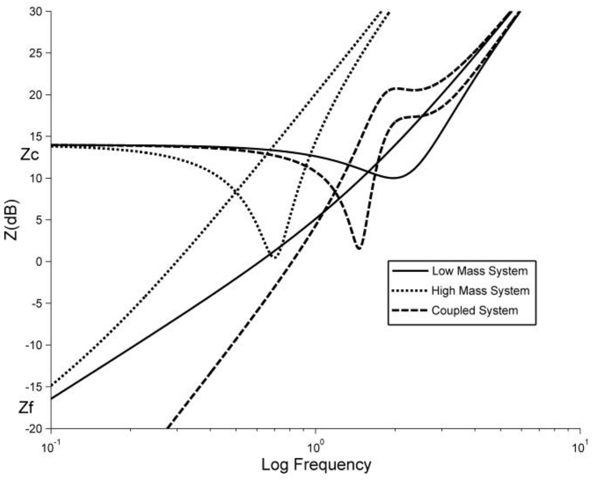
Zc). If the workspace of the device is made larger, then the inertial mass of the system will also increase, scaling as the cube of the length scale. The friction or damping scales as the square of the length scale and the stiffness can be considered proportional [
27]. The closed-loop performance is also affected but it can be assumed that a larger workspace device would have higher values of damping and larger motors which would minimize the effect on the closed loop response. Thus it can be seen that simply scaling the workspace of the haptic device reduces the time constant or natural frequency, this affect can be seen in
Figure 1.
Now consider that rather than increasing the size of the back-drivable device to increase its workspace it is instead mounted on a much larger, high performance servomechanism. The servomechanism attempts to move the base of the smaller haptic device to keep the human interaction point centred relative to its own coordinate frame. The design principles supporting this configuration can be analysed using a simple state space model.
The base system is assumed to have mass m2 and the “carried” haptic interface has an effective mass m1. The implicit assumption is that m1 is chosen to be small allowing the relatively low levels of kinetic energy to be transferred into other components such as the device friction and damping.
The force on mass
m1 is assumed to be the combination of the lighter actuator force
fa and the force exerted by the human
fh. The force on mass
m2 is assumed to be due to a large actuator providing force
f2. Although there will be an additional reaction force on
m2 from the lighter actuator this will be small and treated as a disturbance in the control system. Thus the governing equations are:
The actuator forces are controlled with feedback gains
k1 and
k2, where
f2 = k2x2 and
fa = k1x1. The force on
m2 comes from the actuators, whereas the force on
m1 is the combination of the actuator and the force applied by the person, thus
fa + f1 = fh. The state space form for the resulting system is then:
Equation (4) can be solved in the Laplace domain (assuming all the initial states are 0) as . Since we are primarily interested in the relationship between the force applied by the human, fh, and the resulting movement, x1, this can be recovered from the above as where c1,3 is the row 1, column 3 cofactor of .
This equation can be written in impedance form as:
Several observations can be made from this equation. First the similarity to Equation (1), but with the final term acting as a low pass filter plus differentiator. The gain k2 can be set as high as possible without causing undue under damping or instability to allow fast movement of the base. Once this is achieved the effective impedance of the system is that of the “carried” haptic device and if this is a high quality back drivable device this will be determined primarily by the inherent mass of the interface m1 and the programmed stiffness k1.
The response is only valid up until the servo or smaller device saturates and reaches the limit of its workspace. If we assume that the servo can be made as large as necessary then only the saturation of the back-drivable device is of interest.
For a particular amplitude of input movement that is greater than the workspace of the back-drivable device alone there will be a bandwidth over which the servo is able to keep the smaller device within its workspace. At some frequency , the distance between the position of the servo and the input position will exceed the workspace of the haptic device and it will have reached saturation. The critical value defines the bandwidth over which the system can sustain a level of performance at least as high as the uncoupled back-drivable device. Unlike the simple back-drivable device the performance of the servo mechanism can be increased with minimal adverse effects on either the closed or open loop response. Thus the major limit on the achievable workspace and input bandwidth are the dimensions of the servomechanism and the acceleration it can produce. However, as will be discussed later, as the difference between the accelerations of the servo mechanism and the user interaction point increase, the friction and inertia in the kinematic structure of the small haptic device are no longer negligible and will be perceivable by the user as a disturbance.
The following section presents the design and construction of a prototype coupled haptic interface to test the concepts discussed in this section.
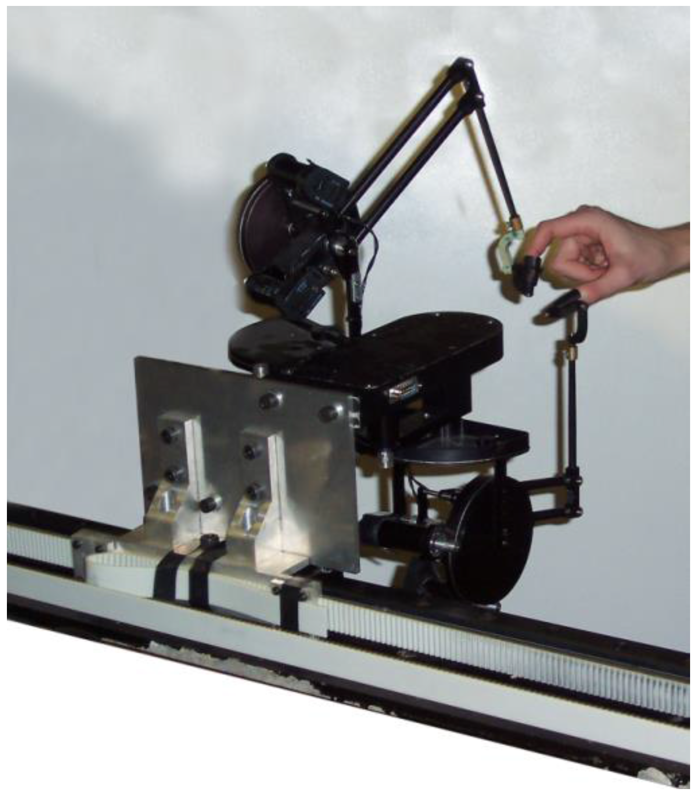
3. Prototype Design
A prototype system, called The Stoat, has been developed consisting of a servomechanism based on a linear track designed to carry two Phantom Premium 1.5 haptic devices (from Sensable) allowing us to study multi-finger dexterous manipulations as in [
28], see
Figure 2.
The servomechanism prototype comprised a 1.6 m TKO linear track driven by two 1500 Watts printed armature DC motors (Printed Motor Works model number: G19M4) connected via a toothed drive belt. The motors have a measured torque constant of 0.7928 Nm/A and are driven at 40 V/10 A by two Maxon ADS 50/10 servo amplifiers. The gearing is such that each motor contributes 28 Newtons pre Amp when converted into linear force by the drive belt. The peak output force is approximately 500 N. Maximum measured velocity in use was greater than 6 ms−1. The position of the platform holding the Phantoms is measured directly via a linear encoder strip. In addition, an ADXL210 ±10 g accelerometer is mounted at the base of the Phantoms to measure the acceleration.
A frequency analysis was performed to calculate the open loop dynamics of The Stoat. From this, the open loop transfer function of The Stoat with two Phantoms attached was found to be:
where the mass is in Kg and the damping is in N/ms
−1 (That is a time constant of approximately 1/6 s). A transfer function was also obtained for the base rotation of a Phantom, as this is the primary degree of freedom taking part in movement in the same direction as the linear track (the remaining axes were fixed at right angles in their default reset position). The resulting transfer function is Equation (7), again the units are in Kg and N/ms
−1.
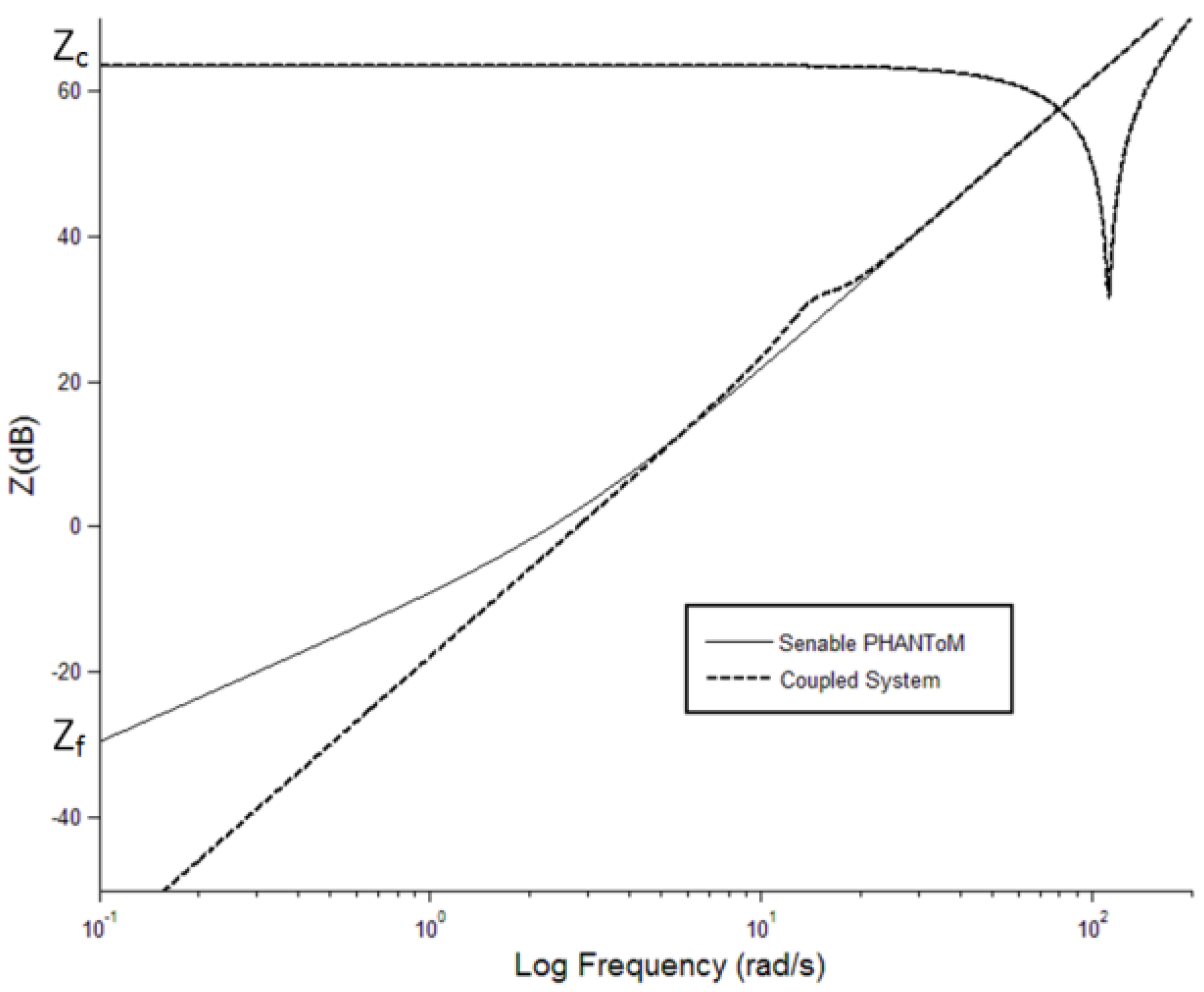
Figure 3 shows the impedance response of the comparison between haptic device and coupled system, using the dynamics values from the prototype. The gain value which the servomechanism uses to centre the haptic device is 1600 Nm
−1 and was found by manual tuning until a responsive, stable performance was achieved. The haptic device’s gain used to demonstrate closed loop response was 1500 Nm
−1 and was chosen by experience as a value close to the upper limit of stability for the device.
As can be seen in
Figure 3 the centring response of the servomechanism to input movement actually results in a lowering of open loop impedance at low frequencies. This was noticeable using the prototype, making the coupled system feel lighter than the haptic device alone. Additionally it is clear that the limiting factor for impedance response in both open and closed loop is the haptic device not the servomechanism.
Figure 3 shows only part of the picture however. The coupled system has two limitations. Firstly, saturation, the point at which the servomechanism lags behind input position sufficiently to cause the haptic device to reach the limit of its workspace. Secondly, assuming the servomechanism is sufficiently powerful, its gain and damping can be adjusted to keep the haptic device centred even at high input accelerations. However, this results in high accelerations of the base of the haptic device, causing the linkages to move and a disturbance force to be perceived at the tip.
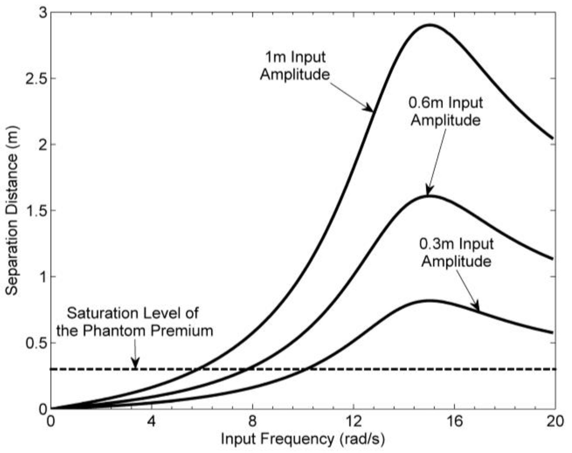
Figure 4 demonstrates the variation of the maximum separation distance between the position of the haptic device tip and servomechanism for a range of sinusoidal input frequencies and three input amplitudes: 0.3, 0.6 and 1.0 m. The values used for mass and damping are those measured on The Stoat and the closed loop gain of the servomechanism is the same as for
Figure 3 (1500 N/m). The horizontal line represents the maximum separation that can be accommodated by the Sensable Phantom Premium 1.5. Frequency and amplitude combinations that have separation distances above this threshold would result in the user hitting the end stops of the Phantom’s workspace.
A simple proportional controller was used to centre the servomechanism. In order to maximize the bandwidth over which the haptic device does not saturate, it is necessary to apply a more sophisticated control algorithm, however, high accelerations of the servo will be perceptible to the user and possibly affect to user interaction. As such, it is necessary to understand what affect different control strategies have on the user’s perception and performance.
4. Evaluation of the Servomechanism Control Scheme
To maximize the input bandwidth and achievable workspace, the servomechanism must respond as quickly as possible with minimal overshoot. However, high servo acceleration will result in disturbances forces being transmitted to the user and so a trade-off exists between workspace-bandwidth performance and perceived device transparency. To understand this trade-off and what it tells us about the design of haptic interfaces based on a macro-micro approach it is necessary to gain an understanding of what affect the different elements of the servo control scheme have on user experience and what can be done to maximize servo performance whilst minimizing the impact on the user.
It has been shown that in point to point reaching tasks humans tend to move in approximately straight lines and the velocity profile can be characterized by a symmetric bell shape [
10]. In light of this expected profile, it was hypothesized that the relationship between servo control scheme and user experience could be better understood by comparing the effect of adding different components into the servo control scheme on the velocity and position traces of users performing repetitive motions.
A small number of informal tests were conducted where individuals were asked to perform a reciprocal tapping task with different components of the control scheme activated. Each subject was asked to alternately tap two targets spaced 0.6 m apart in a quick but smooth and continuous manner.
For each condition, the traces were averaged for each subject separately and compared manually to identify common features. All showed similar features, though some were more pronounced than others. The traces used as examples below were selected because they showed typical features well but were not extreme.
The criteria for a good system response were: to minimise movement of the haptic device (relative to itself) and the similarity of user’s input (combined servo and haptic device) velocity to the natural bell shape expected in a target acquisition task. To objectively asses this difference, the combined velocity profiles were fit to a 5th order polynomial from work on human minimum-jerk movement [
29] resulting in an average sum of squared error (SSE) and goodness of fit (
R2) for each control scheme condition.
4.1. PD Control
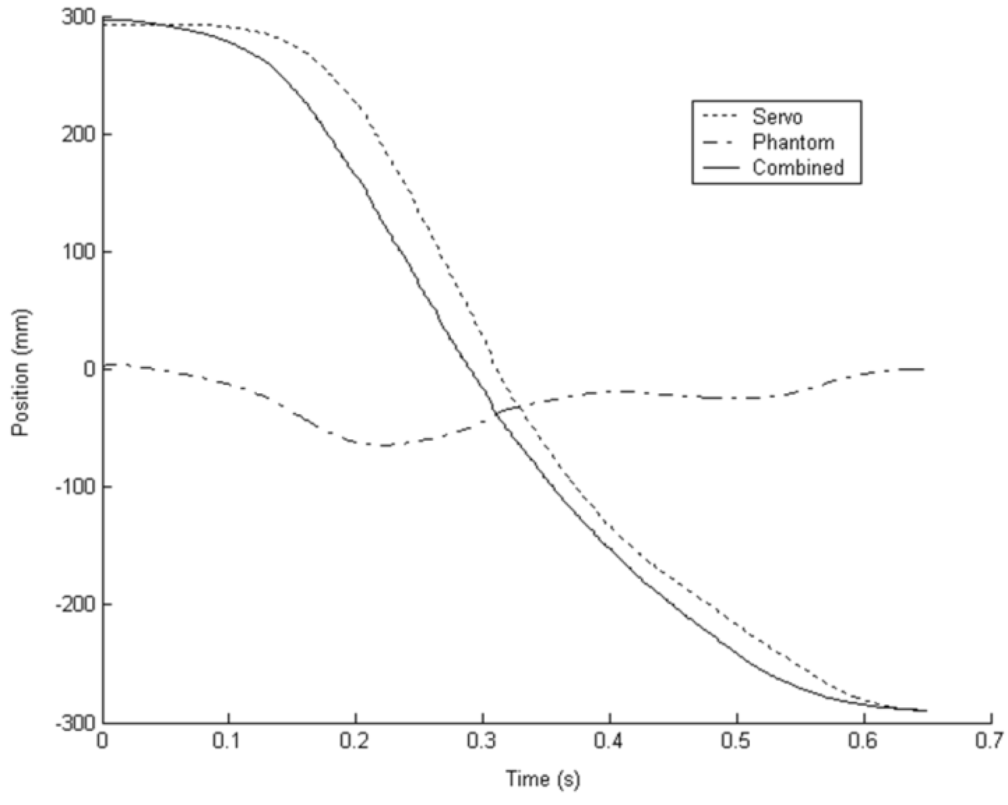
The first condition employed a simple PD feedback controller. The control loop used the distance of the haptic device’s end-effector from the centre of its workspace as the error signal with an extra damping term using the velocity of the servo itself to reduce oscillations. The parameters were tuned manually to give a fast response with minimal overshoot to a step input.
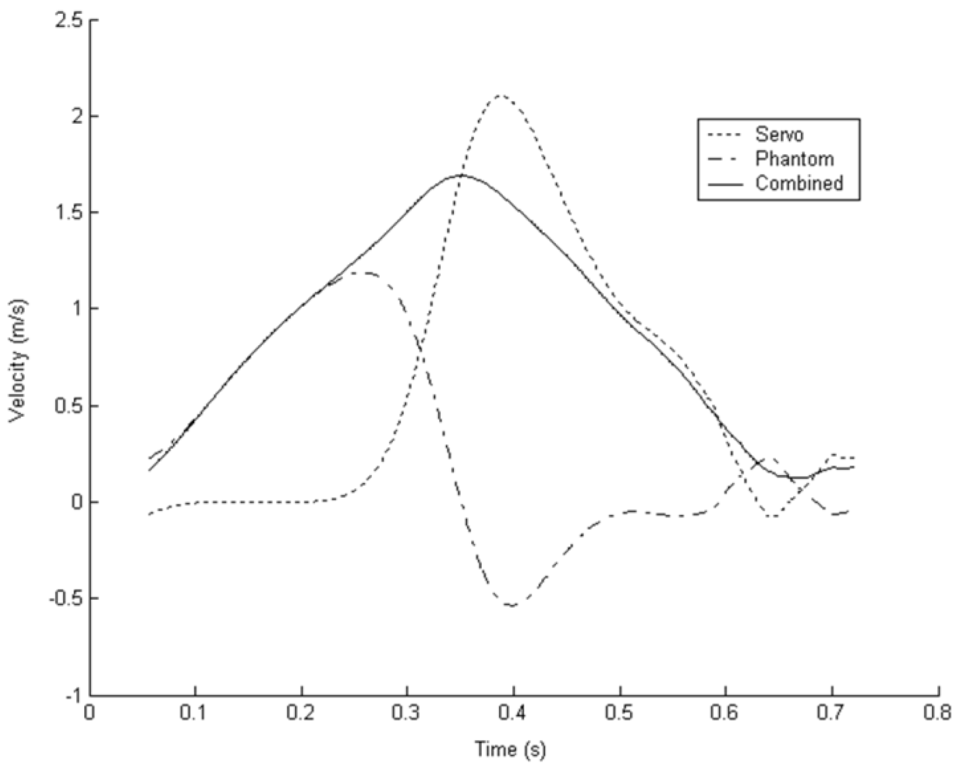
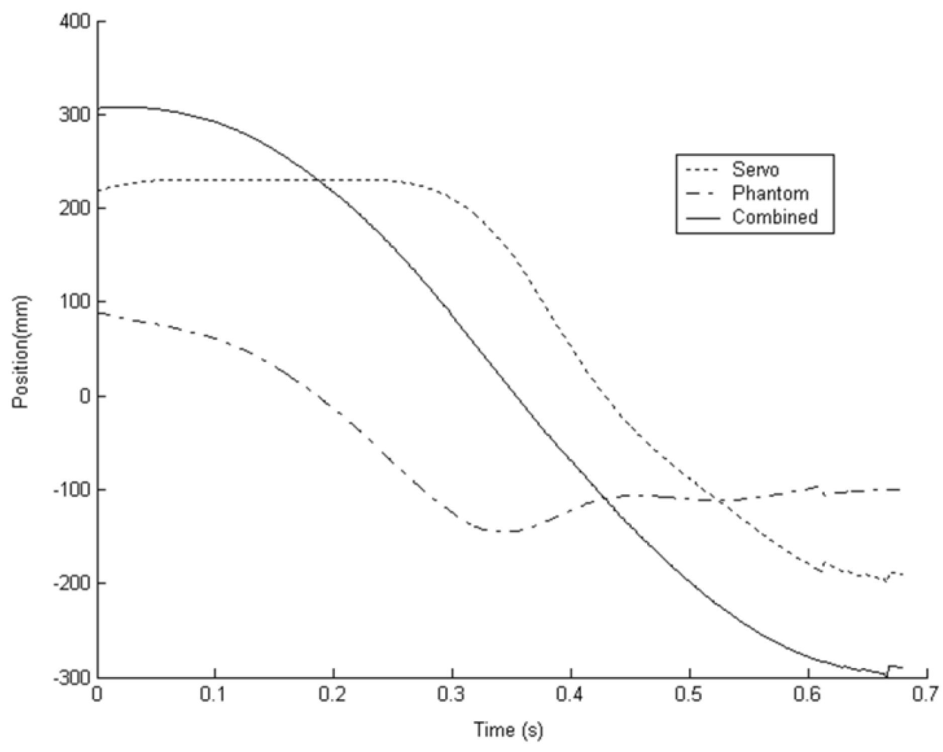
Figure 5 and
Figure 6 show the position and velocity traces respectively for a subject moving to reach a target with this simple PD controller in use. The workspace of the Phantom 1.5 is approximately ±180 mm and in
Figure 5 it can be seen that only a small fraction of this workspace is used with the servomechanism performing most of the movement. However, as the user decelerates, the interaction between servo position and haptic device position causes oscillations. These oscillations and the resultant distortion to the bell shape of the combined velocity profile can be seen in
Figure 6.
4.2. Dead-Band
To reduce oscillation of the servomechanism the second condition added a dead zone of ±100 mm about the centre of the haptic device.
Figure 7 and
Figure 8 show the averaged position and velocity profiles for the dead-band controller. The effect of the dead-band on the motion of the haptic device can be clearly seen. The Phantom haptic device accounts for a much greater portion of the total movement. The ultimate result of this is to reduce the saturation bandwidth for movements greater than the workspace of the haptic device. Oscillations, however, were reduced but at the expense of the bell shape of the combined velocity profile.
The much greater acceleration by the servo has flattened out the acceleration/deceleration portions of the combined movement for most subjects and increased the average peak velocity. It can be assumed from this that the subjects are not moving in the manner which they intended thus reducing the transparency of the system. For comparison with the subsequent results, the average fit of the velocity profiles to the expected bell shape function was SSE = 3.095 and R2 = 0.9719.
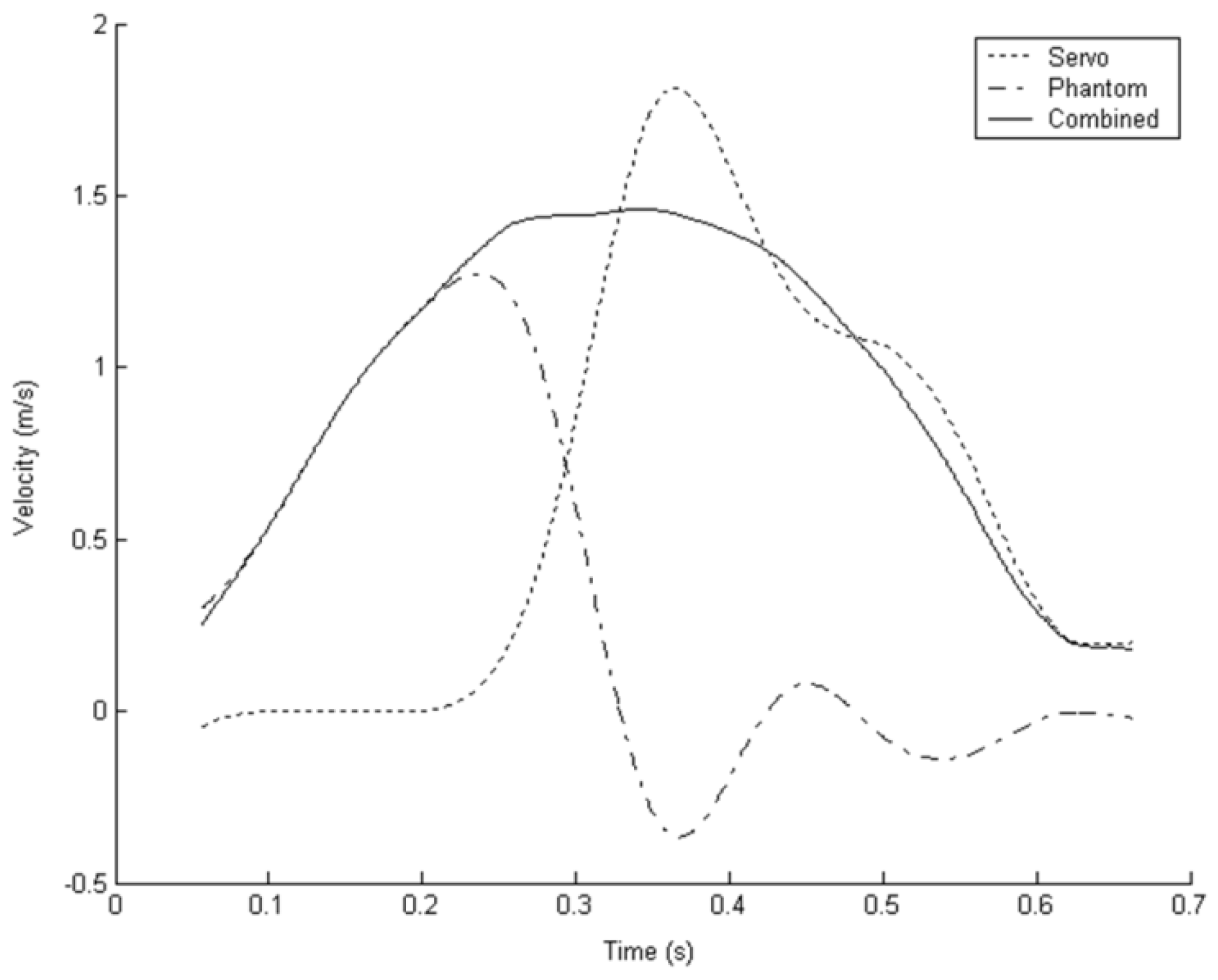
4.3. Velocity Feedforward
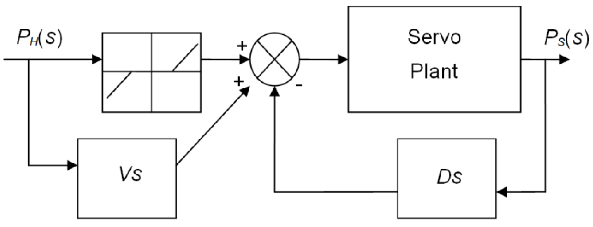
The third condition added velocity of the haptic device into the error signal to smooth out the sharp accelerations of the servo due to the dead-band and also to restore some of the lost saturation bandwidth by allowing the servo more time to respond to high velocity input movement from the user.
Figure 9 shows the schematic of the PD controller with dead-band and haptic velocity feedforward, where V is the haptic device velocity feedforward gain. The velocity is estimated using a finite-differencing scheme over 10 samples at 2 KHz.
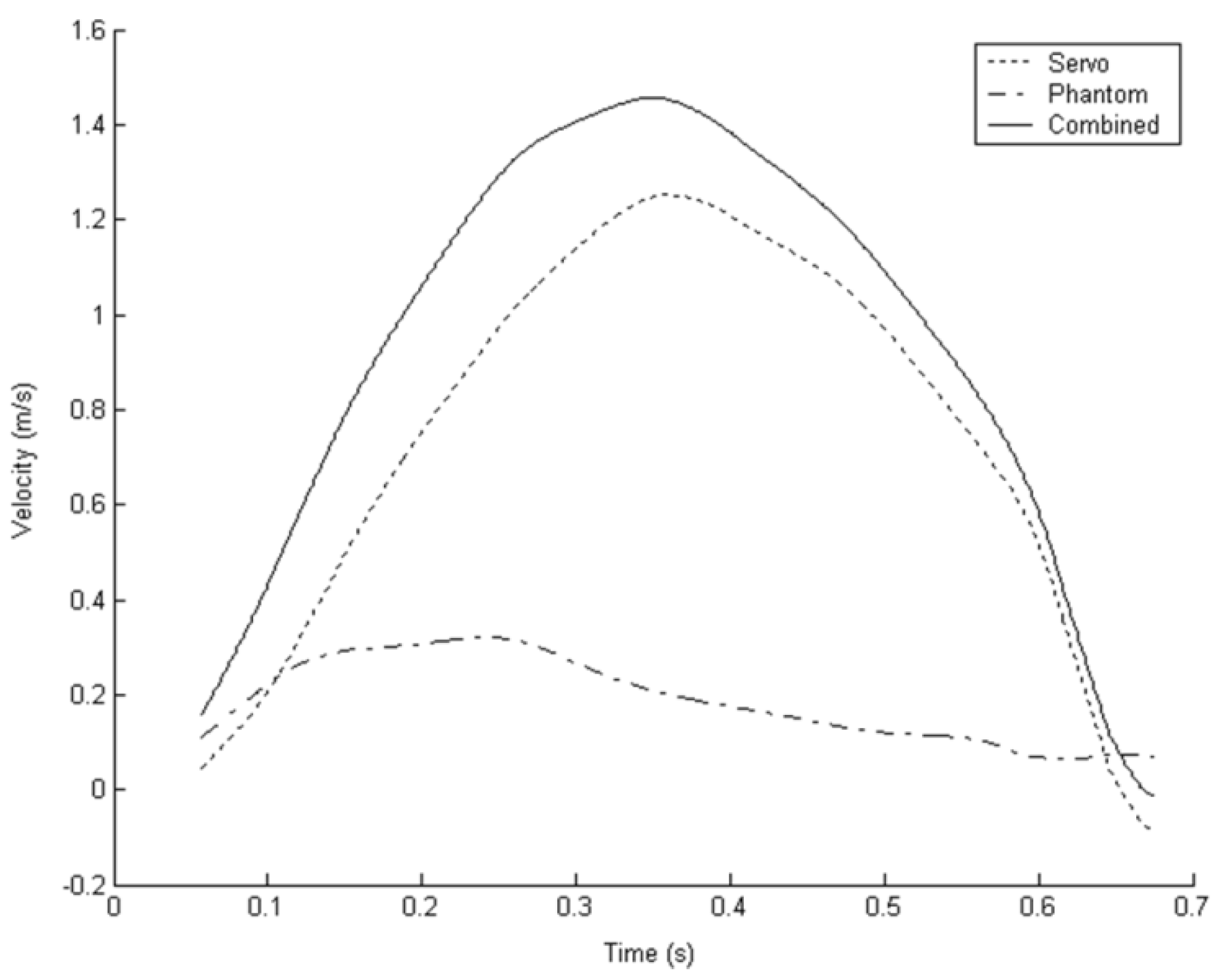
Figure 10 shows a typical velocity profile for subjects performing the task with velocity feedforward active. It can be seen that the motion of the haptic device and the servomechanism is smoother with the resultant combined velocity restoring the shape of the bell curve over the dead-band only condition (SSE = 0.703,
R2 = 0.9939).
4.4. Acceleration Compensation
Adding velocity of the haptic device into the servo controller smoothed out the combined velocity profile as the magnitude of the servo’s acceleration was reduced substantially. However, sudden discontinuous input movements by the user still result in high acceleration of the servomechanism. These high accelerations are felt by the user as disturbance forces, distorting the intended motion and impairing the transparency of the device as a whole.
The disturbances felt by the user are caused by the acceleration of the base of the haptic device. A possible solution is to allow the haptic device controller to apply a precise force to cause an equal but opposite acceleration at the tip, reducing the disturbance felt by the user.
If the dynamics of the haptic device are known then a motor torque for each degree of freedom can be calculated to produce a required acceleration at the tip. It was observed that, due to the balanced design of the Phantom Premium and the friction in the joints, for the range of accelerations the servomechanism produces under normal use, the magnitude of acceleration of the haptic device relative to itself is small. Thus, it is possible to simplify the calculation of tip acceleration by assuming that the acceleration of the distal end of the device,
ad, in world coordinates is simply the acceleration of the base,
ab. In order to counter
ad, the haptic device must apply motor torques which will cause its end-effector to accelerate
−ab. If the acceleration of the base is known then all that is required to calculate the desired joint torques is to convert the acceleration from world to joint coordinates, which can be achieved by differentiating the velocity Jacobian and rearranging for joint space acceleration. The Jacobian and Lagrangian equations, link measurements and inertias used in this work were based on the derivation by Cavusoglu
et al. [
30].
In this condition, the acceleration compensator was applied to the dead-band only controller as the higher base accelerations produce clear trajectory disturbances which the compensator should be able to reduce. However, in practice velocity feedforward would be also be used for best performance.
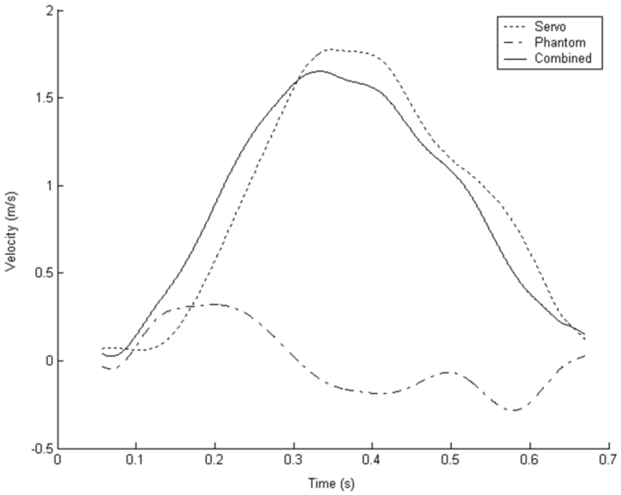
Figure 11 shows a velocity profile for the dead-band controller with acceleration compensation running on the haptic device. When fit to the bell polynomial the resulting average fit had SSE = 0.414,
R2 = 0.9961. Comparing with
Figure 8, the dead-band only plot (average SSE = 3.095,
R2 = 0.9719), it is clear that even though the servomechanism is moving in a similar manner, the resultant combined profile much more closely resembles the desired bell shape. The resultant motion also compares favourably with the velocity feedback controller (SSE = 0.703,
R2 = 0.9939) despite the much more erratic movement of the servomechanism suggesting that the disturbance force has been greatly reduced.
5. Evaluation Using Fitts’ Law
The goal of the coupled system presented in this work is to increase the workspace of the small haptic device without adversely affecting its transparency both for small movements, within the workspace of the small device, and for large, fast movements far exceeding the original workspace.
5.1. Fitts’ Law
Fitts’ Law [
31] is a method of measuring the information capacity of the human motor system by applying concepts from information theory to humans performing quick, aimed movements. The Fitts model is often used to compare and predict the performance of physical computer interfaces in human-computer interaction and has previously been applied to the Sensable Phantom Premium 1.5 by Wall and Harwin [
32] and Chun
et al. [
33].
Fitts’ Law is usually explored by having test subjects perform a series of repetitive movements with varying amplitude and target sizes. While Fitts’ original task involved tapping back and forth between two plates with a stylus [
31], Soukoreff and MacKenzie [
32] recommend a circular pattern to avoid confounding factors related to orientation. Further, Grossman and Balakrishnan [
34] explored a three dimensional Fitts paradigm showing that performance varies with user centred direction.
Fitts introduced the concept of Index of Difficulty (ID), which is measured in bits, and combines the distance of movement (D) with the size of the target (S) into a single variable. For comparison with Wall and Harwin’s study, the tests presented here use the Welford formulation of ID [
35]:
There is a trade-off between movement time (MT) and ID; smaller and more widely separated targets requiring more time to attain than larger or closer ones. It has been widely shown that there is an approximately linear relationship between ID and MT which can be plotted and used to compare the performance of different experimental setups. The same relationship can be expressed as throughput (TP) Equation (9) and is also useful for comparing performance between conditions.
Wall and Harwin compared performance in a standard linear (two targets with varying size and separation) Fitts style test between two conditions: where the subject can see the target but not feel contact and where the subject can both see and feel contact with the target. This makes the study a useful point of comparison as The Stoat prototype should be able to reproduce the performance of the Phantom in both non-haptic and haptic scenarios. In addition, if it is true that extending the workspace has not adversely affected performance, then the inclusion of target separations greater than the workspace of the Premium 1.5 should still result in an equivalent Fitts throughput. To investigate this, a simple Fitts’ Law study was performed on The Stoat.
5.2. Method and Procedure
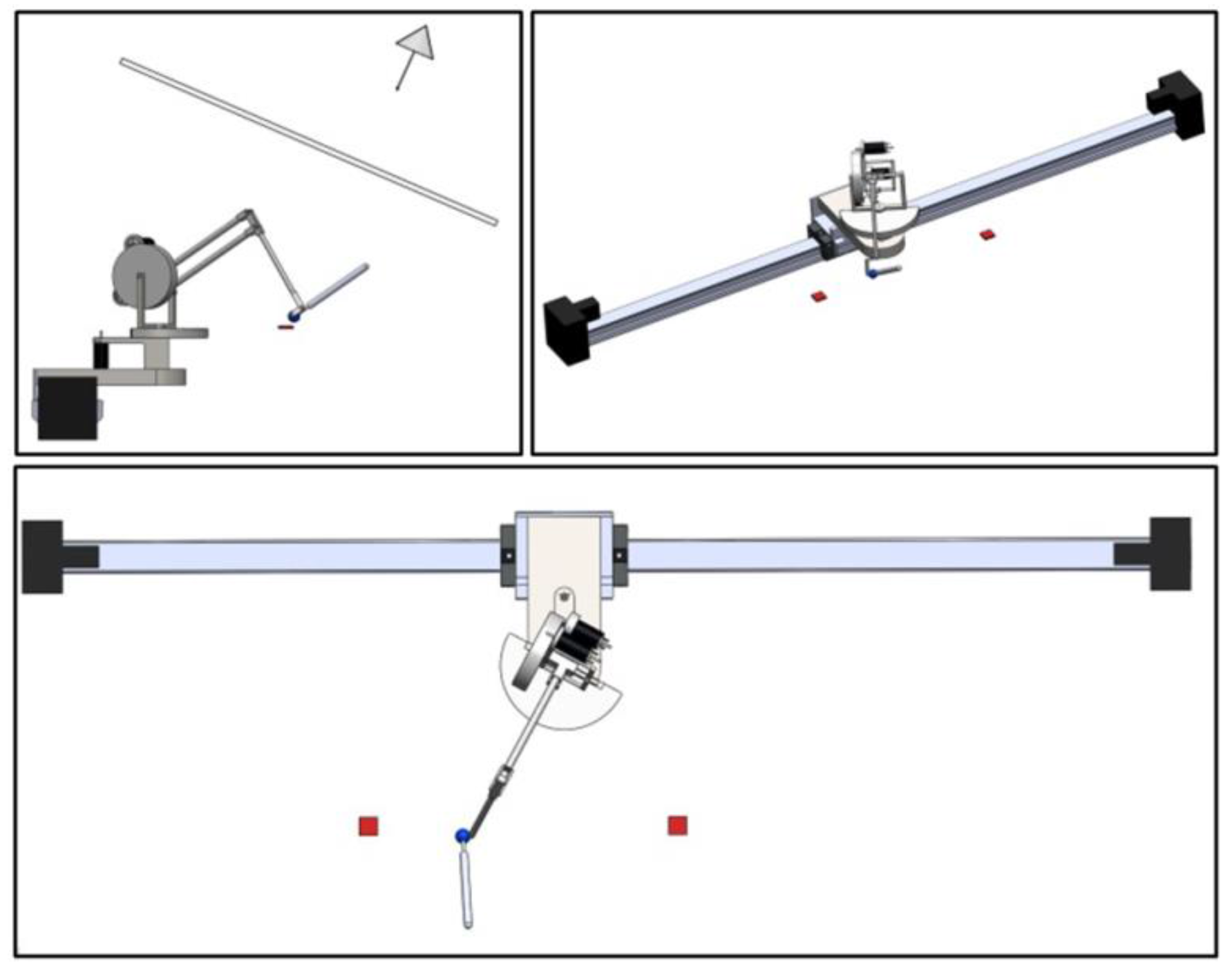
The experimental apparatus used was The Stoat and consisted of a single Phantom Premium 1.5 with the stylus attachment mounted on a 1.6 m linear servomechanism as previously described. This configuration does not easily allow for a display positioned behind the haptic device and instead incorporates a front projected, angled (approximately 30°) display surface which blocks the user’s view of their hands and the haptic device (
Figure 12, top left). This deviates from the setup used by Wall and Harwin but is equivalent to one of the experimental conditions in the study by Chun
et al. Two projectors with circular polarizing filters project onto the display surface and the user wears matching polarized glasses and a head tracking marker so that they see a stereo 3D view of the virtual scene which adjusts to their head position. Configuration of the colocation is achieved by manual measurement of the corners of the projected display with respect to the same common world reference point as the haptic device and origin of the head tracker. The correct viewer-perspective off-axis view frustum is then calculated in real-time using the corners of the display surface and viewer head position. Head tracking was performed using the optical target recognition library ATRoolKit in conjunction with a 640 × 480 pixel, 30 fps uncompressed FireWire camera. The tracking system’s latency was measured as 80 ms, unfortunately precise information on the repeatable position accuracy of the setup is not available.
The end of the stylus is represented graphically by a blue sphere 20 mm in diameter in virtual coordinates and the targets are red cuboids, 3 mm high and of varying width, see
Figure 12. The nature of the perspective graphics means that the actual size of objects on screen (in pixels) changes depending on distance from the user’s viewing position.
Although both 2D and 3D arrangements of targets are recommended in Fitts’ Law studies, this study used a 1D arrangement of target positions (although the user can still move in 3D, similar to Fitts’ original study) as: the prototype system only extends the usable workspace in a single (horizontal) dimension and the previous study using the Phantom Premium by Wall and Harwin was also based on a linear task.
There were six different separation distances used and four sizes of target (
Table 1) making 24 configurations which were presented to the subjects in a Latin Square pattern to control for order effects. Each configuration required 15 taps between the targets before it was completed. Additionally, each subject performed two sets of the 24 configurations, one set without any haptic feedback and one with haptic feedback enabled allowing the user to feel the contact between stylus and target. The order of the haptic and non-haptic sets was also alternated between subjects. A total of ten subjects took part in the study, thus the total number of trials was 10 × 15 × 24 × 2 = 7200.
The subjects were aged between 19 and 37, four females and six males (2:3). All had prior experience with haptic devices, were able-bodied and had normal or corrected to normal vision. The task was explained to each subject and they were asked to complete each trial as quickly as possible but emphasizing accuracy. As all subjects had previous experience with haptic interfaces it was considered that four practice configurations would be sufficient to familiarize them with the task and apparatus. When each new configuration was presented, an audible beep sounded to tell the subject to begin. Timing started from the first contact with either target and the targets disappeared after 15 taps had been completed. The subjects were permitted to rest between configurations whenever they felt tired.
5.3. Results
Calculation of the index of difficulty for each configuration was performed using Equation (8). The value of “S” in Equation (8) was the sum of the target width and the cursor width giving an ID range of 0.4150 to 4.6147 bits. As suggested by Soukoreff
et al. [
36] any data points outside 3 standard deviations of the mean were investigated and removed if they appeared to be outliers. After examination of movement times and corresponding movement traces a total of 47 and 158 trials were removed from the haptic and non-haptic conditions respectively. The movement traces suggest that almost all removed trials corresponded to the subject moving on before making contact with the target resulting in a doubled movement time.
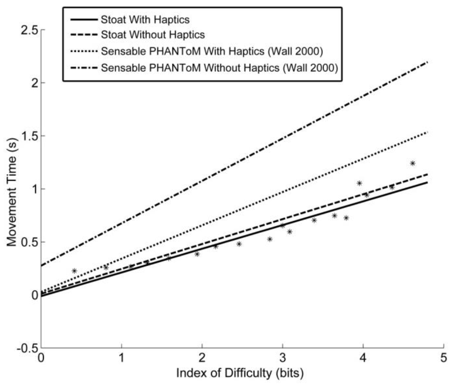
A best fit line was then calculated from the averaged data points for the haptic and non-haptic conditions using linear regression, these were MT = 0.224 × ID − 0.0118 and MT = 0.2346 × ID + 0.0106 respectively.
Figure 13 shows the regression slopes for the Phantom Premium 1.5 by Wall and Harwin in both “haptics on” and “haptics off” conditions compared against those for The Stoat. As can be seen, Wall
et al. found a clear performance improvement for the haptic condition over non-haptic. As the coupled device showed a slight improvement for haptics a test of significance was conducted to verify this. As recommended by Soukoreff
et al. [
36] the mean throughput (ID/MT) was calculated for each configuration and each subject separately for the two conditions. The conditions were then compared as a repeated measures 1-way ANOVA. The result was not significant (F = 1.704,
p = 0.233, η
p2 = 0.196) suggesting the difference was likely due to natural variation and not an effect of haptics. However the performance of the coupled device is better than was found by both Wall and Harwin and Chun
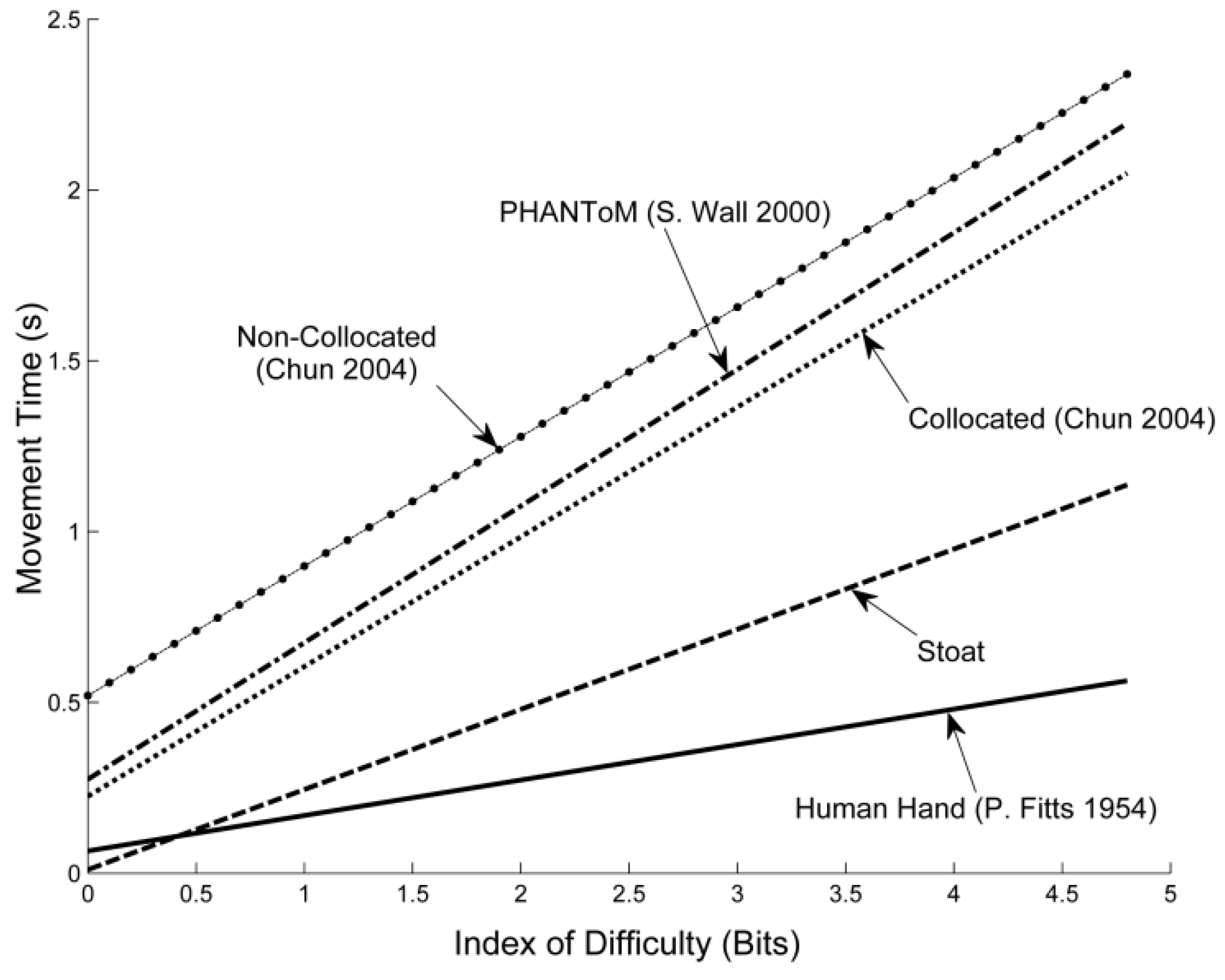
et al. for the Phantom on its own and, as can be seen in
Figure 14, closer to that of the original tests performed by Fitts.
6. Discussion
There is a large body of work demonstrating that the relationship between index of difficulty and movement time in Fitts’ Law holds for a wide variety of conditions including teleoperation. There is no reason to suspect Fitts’ Law would not apply in a virtual environment that includes a haptic interface, yet there are few if any comprehensive studies that study Fitts’ Law in haptics. Fitts’ Law should provide a good indication of device transparency during movement since it encompasses both fine motor skills and ballistic movements. Conditions such as haptic-visual collocation, level of visual cues and the device itself could all be assessed in a Fitts' Law paradigm.
Work by Chun
et al. [
33] used a Phantom Premium haptic device to assess shutter glasses in both collocated and non-collocated conditions. The result published for the non-collocated condition (following conversion to the Welford index of difficulty to allow comparison (This is achieved by assuming that the Welford and Shannon index of difficulty are linearly related.)) was MT = 0.379 × ID + 0.52 which is almost identical to the slope of the Wall non-haptic condition. The best collocated condition, was MT = 0.38 × ID + 0.225 which lies between the Wall non-haptic condition and the Wall haptic condition.
The results of the macro-micro approach above shows a performance benefit over both Chun et al. and Wall and Harwin’s study. Although not expected, it might be explained in two ways. Firstly, at low frequencies the servo part of the coupled system actually reduces the impedance of the whole system, this was quite noticeable on the prototype system and expected from the theory. It is possible that by lowering the impedance of the system it makes the task more like that of the unrestricted human hand. Secondly, in this study we ensured that the haptic and visual conditions were collocated, in comparison to Wall et al. who performed their tests with the graphics displayed on a standard monitor placed in front of the user, thus requiring the operator to associate haptic and visual distances as well as transform between these two coordinate frames. The Chen et al. results partially support this hypothesis, but there are few details on their haptic condition.
Where Wall and Harwin found a significant difference between haptic and non-haptic conditions, this study did not. It is possible that this indicates a reduction in the quality of haptic feedback and thus the subjects were not able to benefit from it. More likely it confirms that the tapping movements were highly learned and the “bounce” of the tap contributed a relatively small amount to the movement time. Alternatively, given that the performance in this study was better in both tested conditions when compared to Wall and Harwin, is possible that, the subjects simply have more of the necessary information provided visually and adding haptic feedback of any quality is only of negligible benefit. This assumption allows a direct evaluation of the transparency of the device by comparing results to other Fitts’ Law studies. There is a need in haptics research to use Fitts’ Law to explore the relationship between transparency, visual cues and level of collocation.
On a more general level of discussion, the approach used here to increase device workspace by linking back driveable haptic device with a servomechanism appears promising. Up to a certain bandwidth, the free space impedance of the coupled system is actually lower than the haptic device on its own and the closed loop impedance is identical at low frequencies, dropping off after a critical frequency. Therefore, for a certain range of frequencies the performance of the system is at least as good as the back-drivable haptic device on its own but over a workspace only limited by the dimensions of the servo mechanism.
The result of this from a design point of view is that, the performance of the back-drivable part of the system can be increased by reducing its workspace, i.e., resulting in reduced free-space impedance and increased closed loop impedance. The usable workspace can then be restored by a sufficiently powerful servomechanism that can actuate the smaller device quickly enough to achieve the required overall bandwidth.
Logically then, the ideal coupled system has a small back-drivable part and a large, powerful servomechanism. However, when the servomechanism accelerates, some of the movement of the haptic device’s base is transmitted to the user due to the inertia of the kinematic linkage. The smaller the back-drivable device becomes, the greater the required acceleration of the servomechanism and thus the greater the disturbance forces felt by the user. Therefore, attention must be paid to the design of the back-drivable device, keeping the kinematics as lightweight as possible, and to applying accurate active acceleration compensation otherwise disturbance forces will be perceptible to the user.
7. Conclusions
The advantages of coupling a back-drivable haptic device to a larger, served positioning system have been discussed and demonstrated with an evaluation using both a comparison to a minimum jerk velocity profile and Fitts’ Law. Using a back-drivable interface as the point of contact, (the micro device) relieves the requirement of having a system with high inertia (the macro device) which must respond almost instantaneously when rendering free space to the user. Thus the back-drivable haptic interface allows for rapid acceleration and deceleration whereas the servomechanism increases the usable haptic workspace. In addition to the results presented here, in general use, the prototype system is capable of keeping the micro device within its workspace at very high input accelerations, with significant and highly unusual effort required from users to exceed it.
Fitts’ Law is especially appropriate for evaluating the performance of this haptic device, in particular it allowed the comparison of fine movements with relatively small amplitudes of movement (50 mm) to ballistic movements over an amplitude of 0.6 m. Results were compared to previously published work. Fitts’ Law may be a good measure to compare disparate haptic devices under a range of visual and visual-haptic conditions since it not only allows comparison across devices and tasks, but also allows transparency to be assessed by comparing results of the original Fitts’ Law target tapping and target capture studies.
Thus this work shows that large workspace haptics operating at high speeds is an achievable goal in a practical haptic device.
There are still problems to be resolved in workspace kinematics, visual environment, and linkage design, but the work raises the potential for haptics in applications such as sports skills training or those requiring a combination of gross and fine movements such as open surgery.


