Article

A Configurable Test Bench for Mechanical Clearance Studies: Multibody Modeling and Experimental Features


by
Zeeshan Hamid Malik
*,
Emilio Sanjurjo
,
Mario López-Lombardero
,
Antonio J. Rodríguez
,
Miguel Á. Naya
and
Francisco González
Laboratorio de Ingeniería Mecánica, Centro de Investigación en Tecnoloxías Navais e Industriais, Universidade da Coruña, Campus Industrial de Ferrol, 15403 Ferrol, Spain
*
Author to whom correspondence should be addressed.
Machines 2026, 14(9), 1073; https://doi.org/10.3390/machines14091073 (registering DOI)
Submission received: 2 August 2026 / Revised: 11 September 2026 / Accepted: 13 September 2026 / Published: 18 September 2026

Abstract

Mechanical clearances are present in mechanical systems due to manufacturing tolerances, assembly imperfections, wear, and material deformation. Their presence can significantly influence dynamic behavior, vibration levels, and long-term component performance. As a result, the characterization, monitoring, and estimation of clearances have become important research topics. Considerable research has been devoted to the dynamic analysis of mechanical systems with clearances using multibody formulations, while more recent studies have explored hybrid model-based estimation techniques and data-driven methods for clearance identification. The development of such approaches requires experimental platforms capable of systematically reproducing and investigating clearance-induced dynamic behaviors. This work presents the development of a configurable slider–crank test bench designed for experimental investigation of mechanical clearance, which allows the selection of clearance location and magnitude, operating speed, and mechanism orientation. A multibody model was developed to support the system design, monitor its operation, and provide a numerical reference for the obtained experimental data, retrieved from accelerometers and encoders. The results obtained during experimental tests demonstrate that the platform generates repeatable measurements while remaining sensitive to variations in operating conditions and clearance configurations. Results also served to assess the ability of multibody formulations and clearance modeling approaches to correctly characterize the dynamic effects caused by joint clearances. Formulations that describe the system motion using minimal coordinates resulted in reduced uncertainty in simulation results. The selected contact models succeeded at capturing the effect of revolute joint clearances on the accelerations of the mechanism, establishing a first step in the detailed description of the contact dynamics that is necessary for the use of forward-dynamics simulation results in the development of hybrid model-based and data-driven clearance characterization methods.

1. Introduction

Advances in science, technology, and modern industry have increased the reliance on mechanical systems operating under demanding conditions, including high loads, friction, and wear. These systems typically consist of interconnected components linked through various types of joints, which play a critical role in transmitting motion and forces. During operation, joint contact surfaces are subjected not only to external loads but also to continuous relative motion, which leads to the development of wear. Over time, this wear can generate mechanical clearances that alter the intended kinematic and dynamic behavior of the system, degrading performance, increasing vibration levels, and reducing operational reliability. Therefore, the timely detection and characterization of mechanical clearances are essential to prevent machine failures, reduce maintenance costs, and, in critical applications, avoid risks to human safety.
Mechanical clearances arise from manufacturing tolerances, assembly imperfections, material deformation, and progressive wear, creating unintended gaps between contacting joint surfaces. Although a certain level of clearance is unavoidable in practical applications, undesired clearance introduces additional relative motion and alters the intended behavior of the mechanism [1]. The existence of joint clearance results in highly nonlinear dynamic phenomena, including intermittent contact, impacts, friction-induced effects, backlash, increased vibration levels, and energy dissipation. These phenomena can substantially alter the dynamic response of a mechanism, degrade motion accuracy, accelerate component deterioration, and reduce the operational reliability of industrial machinery. In severe cases, excessive clearance may lead to functional failure and costly downtime. Since wear is one of the primary mechanisms driving clearance growth, understanding and characterizing clearance-induced dynamic behavior has become an important topic in multibody dynamics research. The accurate modeling, estimation, and monitoring of clearance are essential not only for evaluating system performance but also for supporting condition monitoring and predictive maintenance strategies.
Multibody dynamics has become a widely adopted framework for investigating the influence of joint clearances on mechanical system behavior. While conventional formulations often represent joints as ideal kinematic constraints, realistic models account for the existence of clearance by introducing contact-impact interactions between the bodies connected by the affected joint. These interactions result in highly nonlinear responses characterized by intermittent contact, impacts, friction, and backlash [2].
Over the past decades, extensive research has focused on the development of clearance joint models and their application to benchmark mechanisms such as the slider–crank system [2]. Revolute clearance joints have received special attention, although studies on translational clearance exist as well [3,4,5,6]. These studies have shown that the dynamic response of the mechanism is strongly influenced by clearance size, joint location, contact circumstances, and operating speed. In particular, clearance joints located closer to the driving crank were found to experience higher contact forces and wear rates, while variations in operating conditions could induce substantial changes in system behavior, including transitions between periodic and chaotic responses [7,8,9,10]. Multibody simulation has proven to be a useful tool for comprehending clearance-induced dynamics and forecasting the corresponding deterioration of system performance. Most of the employed formulations rely on contact-impact models based on constitutive relations, such as the Hunt–Crossley [11] and Lankarani–Nikravesh [12] formulations, to describe the interaction forces between contacting bodies [13]. Despite their usefulness, clearance joint models remain highly dependent on contact parameters such as stiffness, damping, friction properties, and restitution characteristics. These parameters are often difficult to identify accurately and may vary with operating conditions, lubrication state, and progressive wear. Consequently, reliable experimental data are essential not only for model calibration and evaluation but also for the development of methodologies capable of monitoring and estimating clearance-related parameters under realistic operating conditions.
Obtaining an accurate description of clearance-induced phenomena has been the target of a large number of publications by the multibody research community, e.g., [2,14]. The resulting representations are useful in capturing the behavior of mechanical systems subjected to clearance, and enable the prediction of the effects caused by this issue when the defect has been accurately characterized, i.e., when its location and nature have been determined, and its model parameters, such as contact stiffness and clearance gap, have been identified with reasonable accuracy. A complementary line of research that has received comparatively less attention in multibody dynamics research focuses on characterizing clearance from the dynamic response of the mechanical system. According to this approach, experimental data from sensors mounted on the mechanical system could be used to infer the existence of joint clearances and estimate their size. The ability to perform this task would enable the development of predictive maintenance solutions. In the vast majority of cases of industrial interest, however, sensors cannot be directly placed at all relevant locations. Moreover, important information about clearances, such as the defect size, cannot be directly measured without dismantling the affected machine. Virtual sensing through the use of state, parameter, and input observers is a practical workaround to overcome these issues. In multibody dynamics, Kalman filters have been successfully used to develop such observers, merging experimental and simulation data, and demonstrating the potential of estimation frameworks to infer quantities that cannot be directly measured [15]. This method has recently been applied to the estimation of clearance size [16,17,18] using synthetic data from multibody simulations.
In parallel, data-driven methodologies have also been explored as an alternative means of extracting clearance information directly from measured vibration signals. These approaches, ranging from conventional machine learning techniques to deep learning architectures, have shown promising capabilities for recognizing clearance-related patterns without the need for explicit physical models [19]. Initial results have confirmed the ability of neural networks to characterize clearance parameters, again using synthetic data from numerical simulations. The methods developed following this line of research will benefit from the confirmation of their findings with experimental data, and this requires dedicated test platforms that can generate controlled, repeatable, and well-characterized clearance conditions. Additionally, the experimental data retrieved from the test bench will be the starting point for the formulation of clearance prediction methods that mix model-based and data-driven approaches. Experimental data are difficult and often expensive to obtain, especially in industrial environments. Synthetic data, conversely, are easier to generate, but may not accurately describe the behavior of the system under study if the computational methods used to obtain them do not capture critical aspects of its dynamics that depend on parameters and models with considerable levels of uncertainty. The combination of both approaches is a promising way to alleviate experimental data scarcity while overcoming the issues of computational descriptions, but it needs to rely on the validation delivered by experiments performed in carefully controlled test environments.
This article presents the development of a configurable slider–crank test bench for the experimental investigation of the mechanical clearances and describes its mechanical design, instrumentation architecture, calibration procedures, configurability features, and data-processing. The developed test bench enables the on-purpose introduction of clearances at different joints, while allowing systematic variation of clearance magnitude, operating speed, and mechanism orientation. To complement the experimental infrastructure, a multibody model of the mechanism was developed to support system design, experimental interpretation, and the generation of the representative synthetic data. The test bench was experimentally characterized under multiple operating conditions to assess its dynamic response, measurement repeatability, and sensitivity to the clearance variations. The acquired results demonstrate the capability of the platform to generate controlled, reproducible, and configurable datasets, establishing an experimental framework for the development and evaluation of model-based and data-driven mechanical-clearance estimation methodologies.

2. Experimental Test Bench Design and Development

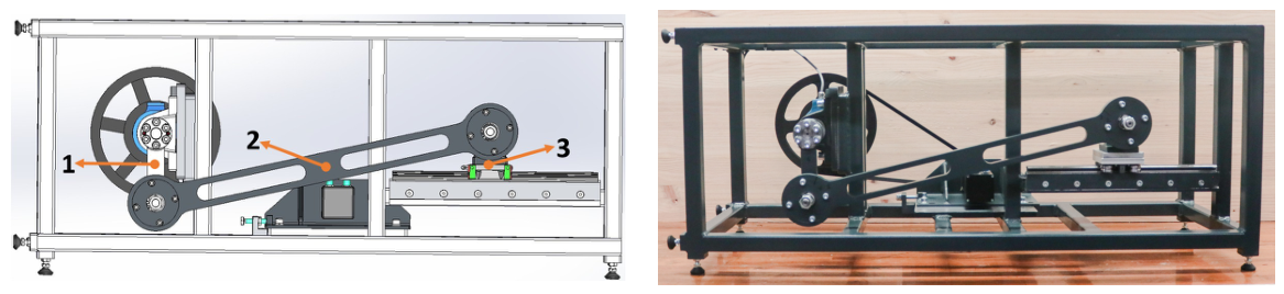
The developed slider–crank test bench is intended to provide a controlled platform for the investigation of mechanical clearances and the acquisition of sensor data under configurable operating conditions. The platform was conceived to support the experimental assessment of clearance-related phenomena and to generate datasets for the development and evaluation of clearance estimation methodologies. Figure 1 presents the CAD model and the actual experimental prototype of the test bench. Similar test benches can be found in the multibody dynamics clearance literature, e.g., [20,21], although often with smaller dimensions. The larger size of the present bench is expected to bring its behavior closer to that of industrial machinery.

2.1. Mechanical Design

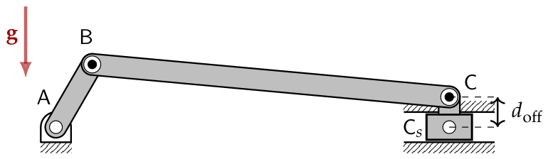
Figure 2 shows a kinematic diagram of the slider–crank test bench. The mechanism consists of four bodies: the ground, crank (body 1), connecting rod (body 2), and slider (body 3), interconnected through revolute and translational joints. The crank is actuated by an electric motor through a belt transmission. The rotational motion of body 1 is transmitted to the connecting rod, which subsequently drives the translational motion of the slider.
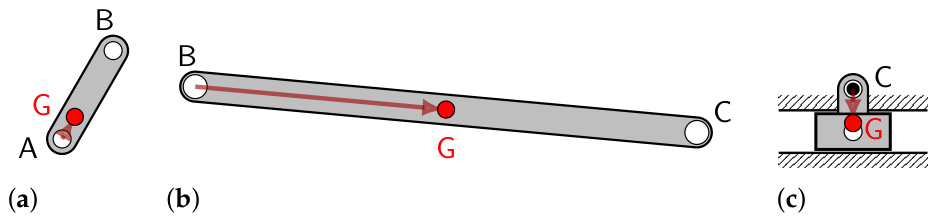
The geometric and inertial properties of the mechanism are summarized in Table 1 and Figure 3. The mass of each body was measured with a scale. Its inertia was determined from the CAD model of each component, once its mass was known. The mass and inertia of the crank include also those of its shaft and the pulley that transmits the motor torque. The inertia values in Table 1 are referred to the center of mass of each body. The x G coordinate of the center of mass of each body is the distance to its origin point ( A for the crank, B for the connecting rod, and C for the slider) measured along its longitudinal axis.
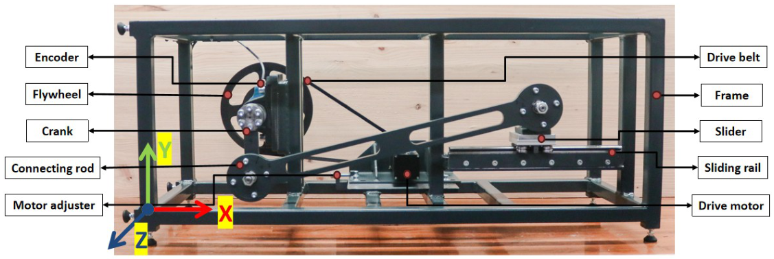
The test bench was specifically designed to facilitate the on-purpose introduction of mechanical clearances while preserving the nominal geometry of the mechanism. Controlled radial clearances can be introduced at the crank–connecting rod and connecting rod–slider revolute joints, whereas a two-sided clearance can be introduced at the slider-guide interface. This modular architecture enables the reproduction of different degradation scenarios under controlled laboratory conditions and supports systematic investigations of their influence on sensor measurements. Figure 4 shows the main components of the experimental setup.

2.2. Configurable Features

The developed test bench incorporates several configurable mechanical and operational features that enable systematic investigations of clearance-induced dynamic phenomena under controlled laboratory conditions. These features include adjustable joint clearances, variable operating speeds, and multiple mechanism orientations, allowing a broad range of experimental scenarios to be reproduced.

2.2.1. Adjustable Joint Clearances

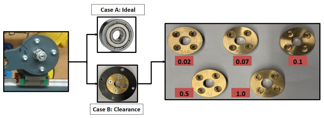
The mechanism is designed to enable the introduction of revolute clearances at the crank–connecting rod joint ( B ) and the connecting rod–slider joint ( C ). A two-sided clearance can also act and the slider–guide interface. In the present study, clearance at the slider–guide interface was minimized using an adjustable linear guide system with preloaded guide bearings, whose preload can be adjusted to eliminate guide clearance and ensure an ideal translational motion of the slider. The revolute-joint clearances, in contrast, are introduced using interchangeable bushing assemblies. Figure 5 illustrates the two joint configurations (Case A and Case B) available in the test bench. Case ‘A’ employs a precision deep-groove ball bearing to provide an essentially clearance-free reference condition, whereas the case ‘B’ uses interchangeable bushings to introduce prescribed radial clearances. The available diametrical clearance values are 0.02 mm, 0.05 mm, 0.07 mm, 0.10 mm, 0.50 mm, 1.00 mm. The clearance-free configuration (Case A) was adopted as the reference condition for all experimental comparisons.

2.2.2. Variable Operating Speed

The test bench can operate over a wide range of rotational speeds, enabling the investigation of excitation-frequency effects on the dynamic response of the mechanism. Motion is transmitted from the motor to the crank through a belt-drive system with a transmission ratio of 1:3.97. For the experimental investigations reported in this work, crank speeds corresponding to motor operating conditions of 250, 500, and 750 rpm were considered.

2.2.3. Adjustable Mechanism Orientation

The supporting structure allows the entire mechanism to be reoriented along the x-, y-, and z-directions. This capability enables controlled modification of the gravitational loading relative to the clearance joints and provides additional flexibility for future experimental investigations. Although the test bench can operate in all three orientations, the experimental characterization presented in this work is limited to the y-vertical orientation configuration.

2.3. Instrumentation

The developed test bench integrates data-acquisition, actuation, and sensing systems to monitor the dynamic response of the slider–crank mechanism under various operating conditions. Particular emphasis is placed on the measurement of acceleration signals associated with clearance-induced impacts and contact phenomena within the mechanism.

2.3.1. Data Acquisition

An MCC USB-1808X data acquisition (DAQ) device (Measurement Computing Corporation, Norton, MA, USA). is used to capture all MEMS accelerometers signals. The system provides simultaneous-sampling analog inputs with an 18-bit analog-to-digital converter (ADC) resolution, allowing concurrent acquisition of all measurement channels and minimizing phase errors between signals. The USB-1808X supports per-channel sampling rates of up to 200 kS/s, making it suitable for capturing both low-frequency kinematic responses and high-frequency acceleration phenomena associated with clearance-induced contact and impact events.
A custom python acquisition application was developed to configure the measurement channels, generate the motor command voltage, and record the accelerometer and encoder signals. During the experiments, all measurements were acquired at a sampling frequency of 100 kHz. This sampling rate was selected to accurately capture the mechanism dynamics while preserving the high-frequency acceleration components generated during intermittent contact and impact conditions.
The DAQ system simultaneously acquires the analog outputs of the six MEMS accelerometers together with the encoder signals, providing time-consistent measurements of the local acceleration responses at joints B and C , slider acceleration, and crank angular position. The acquired data are subsequently processed to obtain acceleration, crank angle, and angular velocity information for the computational and experimental analyses presented in this work.

2.3.2. Actuation System

The slider–crank mechanism is driven by a Maxon IDX 56L ENC S IO (24 V) brushless motor (Maxon Group, Sachseln, Switzerland) with an integrated controller. The motor provides a nominal continuous torque of 795 mNm and a peak torque of 1589 mNm for short-duration operation. Motor parameterization and control settings are configured using the EPOS Studio software 3.7 environment. For the present study, the controller was configured such that an analog command voltage in the range of 0–10 V, supplied by the MCC USB-1808X data acquisition system, corresponds to a motor speed range of 0–1000 rpm. The drive system incorporates a single-turn absolute encoder with a resolution of 12 bit (4096 counts per revolution). The encoder feedback is used internally by the motor controller for closed-loop speed control.

2.3.3. Acceleration Measurements

Acceleration measurements are used to characterize the dynamic response of the mechanism and to identify signatures associated with clearance-induced impacts as well as intermittent and sustained contact. The sensor arrangement is designed to provide local measurements in the vicinity of the investigated joints while simultaneously monitoring the motion of the slider.
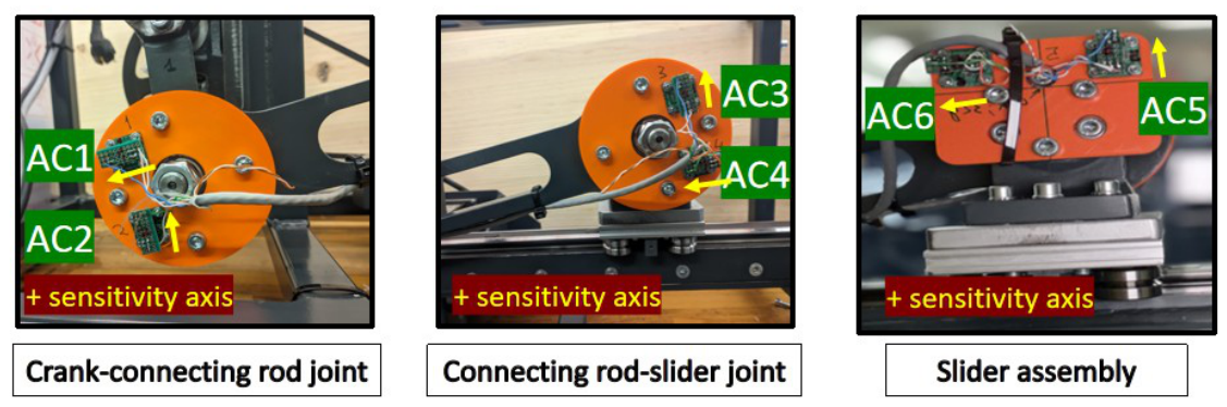
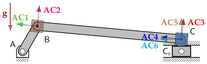
A total of six uniaxial MEMS accelerometers are installed on the test bench. Two ADXL1001 accelerometers, denoted AC1 (longitudinal) and AC2 (perpendicular), are mounted near joint B (crank–connecting rod joint). Similarly, two additional ADXL1001 accelerometers (Analog Devices, Inc., Wilmington, MA, USA), AC4 (longitudinal) and AC3 (perpendicular), are installed near joint C (connecting rod–slider joint). The slider assembly is instrumented with two ADXL1002 (Analog Devices, Inc., Wilmington, MA, USA) accelerometers, AC5 (vertical) and AC6 (horizontal), respectively. The accelerometer locations enable the monitoring of dynamic phenomena in the vicinity of the clearance joints while also capturing the overall vibration response of the mechanism. Figure 6 illustrates the location and orientation of the accelerometers used in the experimental campaign. The ADXL1001 accelerometers have a sensitivity of 20 mV g−1, whereas the ADXL1002 accelerometers provide a sensitivity of 40 mV g−1. These sensitivity values were subsequently used in the signal processing and calibration procedure to convert the measured voltages into acceleration values. According to the manufacturer specifications, the corresponding noise densities are approximately 30 g/Hz and 25 g/Hz, respectively. The ADXL1001 and ADXL1002 accelerometers provide a linear frequency response from DC to 11 kHz (3 dB bandwidth), enabling the measurement of both low-frequency motion components and high-frequency acceleration signatures associated with clearance-induced contact and impact events.
A SICK DGS80 incremental encoder (SICK AG, Waldkirch, Germany) is mounted on the crankshaft to measure its angular position. The encoder signals are used for crank-angle tracking and cycle identification during the experimental investigations. The encoder is sampled using 4× counting, resulting in an effective resolution of 32,768 counts per revolution and a corresponding angular increment of approximately 0.011° per count.
Calibration Procedure
Prior to the experimental campaign, all MEMS accelerometers were statically calibrated to determine their zero-g offset voltages. The calibration procedure was performed with the connecting rod positioned horizontally and verified using a high-precision leveling instrument. Under this configuration, accelerometers (AC1, AC4 and AC6) whose sensitive axes were perpendicular to gravitational direction were subjected to approximately 0 g, whereas accelerometers (AC2, AC3 and AC5) whose sensitive axes were aligned with gravity were subjected to approximately +1 g. For sensors under the 0 g condition, the zero-g offset voltage was determined as the mean value of the recorded calibration signal using Equation (1):
V 0 g = 1 N i = 1 N V i ,
where N denotes the number of acquired samples and V i the measured voltage.
For sensors under the +1 g condition, the corresponding zero-g offset voltage was estimated using
V 0 g = V + 1 g S ,
where V + 1 g is the average voltage measured under the +1 g condition and S is the accelerometer sensitivity. After determining the offset voltage, the acquired accelerometer voltages were corrected according to Equation (3), where V meas is the voltage measured by the accelerometer and V 0 g is the corresponding zero-g offset voltage.
V corr = V meas V 0 g
Finally, the corrected voltages were converted into acceleration values using Equation (4), where a g is the acceleration expressed in units of g. The resulting calibrated acceleration signals were used for all subsequent processing and analyses.
a g = V corr S .
The crank-angle measurement system, the incremental encoder, was also referenced prior to the experimental campaign. During encoder installation, the encoder mounting sleeve was adjusted such that the zero-count position corresponded to the crank aligned with the negative y-axis. This reference position was maintained throughout the experimental campaign and served as the angular reference for crank-angle tracking and cycle identification.

3. Multibody Methods

State, input, and parameter observers built using Kalman filter approaches require a computational model of the system that they monitor. In the case of neural networks, in principle they could be trained exclusively with experimental results, but the availability of synthetic data of good quality can be used to reduce the cost and speed up this process. In this work, the dynamics of the test bench is described by means of a multibody model of the system formulated using dependent coordinates. Although independent-coordinate approaches could also be used, a set of dependent coordinates was selected because it simplifies the replacement of perfect joints by others affected by clearance with minimal modifications in the system equations.
The dynamics of a multibody system defined with a set of n dependent coordinates, q , subjected to m kinematic constraint equations Φ = 0 can be expressed as
M q ¨ + Φ q T λ = Q
Φ q = 0
where M is the mass matrix, Φ q = Φ / q is the Jacobian matrix of the constraints, λ is a set of m Lagrange multipliers, and Q includes the applied forces [22]. In the example considered in this work, all the constraints can be considered holonomic and scleronomic, so their configuration-level expression is a function of the system coordinates, but not of time t.
Equations (5) and (6) are a system of differential-algebraic equations (DAEs). A common approach to handle these numerical problems is transforming them into a system of ordinary differential equations (ODEs) by replacing Equation (6) with its second derivative with respect to time:
Φ ¨ = Φ q q ¨ + Φ ˙ q q ˙ = 0
The resulting system of equations can be written as
M Φ q T Φ q 0 q ¨ λ = Q Φ ˙ q q ˙
The direct solution and numerical integration of system (8) gives rise to several issues. In the first place, its leading matrix is singular if the constraints Jacobian Φ q does not have a full row rank, as is the case in systems with redundant constraints or singular configurations [23]. Moreover, because the kinematic constraints are only enforced at the acceleration level, constraint violations at the velocity and configuration ones may accumulate over time, a phenomenon that is known as constraint drift. Some multibody formulations, based on Baumgarte’s stabilization technique, have been proposed to correct these issues. The penalty formulation [24] is a well-known example in which the expression of the Lagrange multipliers in (8) is replaced with
λ = α Φ ¨ + 2 ξ Φ ˙ + ω 2 Φ
where α is a penalty term, and ξ and ω are damping and stiffness parameters that play a role similar to that of Baumgarte’s terms. Equation (9) makes the constraint reactions proportional to the constraint violations at the configuration, velocity, and acceleration levels. This modification makes it possible to rewrite system (8) as
M + α Φ q T Φ q q ¨ = Q α Φ q T Φ ˙ q q ˙ + 2 ξ Φ ˙ + ω 2 Φ
which is a set of n ODEs with a symmetric, positive-definite leading matrix, regardless of the rank of the constraints Jacobian, provided that an appropriate penalty factor has been selected. Moreover, the stabilization terms in the right-hand side of Equation (10) alleviate constraint drift. The penalty formulation, however, still requires a careful tuning of its parameters to deliver an accurate performance [25,26]. Additionally, it cannot achieve an exact fulfillment of the kinematic constraints, as some level of constraint violation is always required to develop reaction forces and torques. Improved versions of the penalty formulation, such as the augmented Lagrangian method [27], have also been proposed in an attempt to overcome these problems. Even though these methods certainly improve the behavior of the original penalty formulation, they still require parameter tuning and often need special actions, such as the use of projections, to completely remove constraint violations. Parameter tuning is particularly critical in systems with mechanical clearances, as the parameters must be chosen in terms of the system frequencies [25]. In mechanisms with clearances, the overall motion often takes place at a relatively low frequency, while the impacts and vibrations at the joints affected by the defect introduce high-frequency components. In practice, this complicates the task of selecting appropriate formulation parameters, increasing the risk of introducing numerical compliance in the constraints, which leads to artificial energy dissipation, or, conversely, making the system stiff and introducing instabilities in its solution process.
Another way to transform Equations (5) and (6) into a system of ODEs is expressing the dynamics in terms of a set of r independent coordinates z . This can be done by means of a velocity transformation [22]:
q ˙ = R z ˙
where z ˙ is an array of r independent velocities that can often be selected as a subset of q ˙ , and R is an n × r velocity-transformation matrix that verifies
Φ q R = 0
The velocity transformation (11) can be used to convert Equation (5) into
R T M R z ¨ = R T Q M R ˙ z ˙
which is a system of r ODEs. This transformation method is often referred to as the R-matrix formulation. In the simulation of mechanical systems with clearances, the formulation in (13) is advantageous when compared to penalty-based methods, because it results in the satisfaction of the kinematic constraints down to machine precision, and does not require parameter tuning. For these reasons, it has been used in the kinematics and dynamics simulations reported in this paper.

Slider–Crank Multibody Model

To investigate the dynamic response of the test bench under different clearance conditions, a multibody model of the slider–crank mechanism was developed using natural coordinates [22]. The model also serves as a reference framework for comparing the experimentally measured responses with the predictions obtained from numerical simulations.
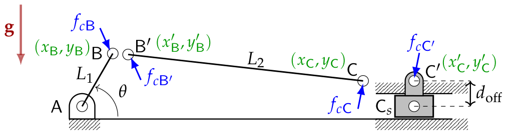
Figure 7 illustrates the adopted multibody representation. Radial clearances are introduced at the crank–connecting rod joint through the clearance pair ( B , B ) and at the connecting rod–slider joint through the clearance pair ( C , C ) . The coordinates of the clearance nodes are represented by ( x B , y B ) , ( x B , y B ) , ( x C , y C ) , and ( x C , y C ) , respectively. Contact interactions occurring at the clearance interfaces are represented through the contact forces f c B , f c B , f c C , and f c C , which become active when contact between the corresponding pin and bushing surfaces is established. In addition, the offset d off between the connecting rod–slider revolute joint C and the slider reference point C s is explicitly included in the formulation in order to reproduce the geometry of the experimental mechanism.
The motion of the mechanism is described using the Cartesian coordinates of selected points associated with the clearance pairs and the mechanism bodies. In the ideal case, where all joints are assumed to be perfect, the coordinates of joints B and C would be sufficient to define the system configuration. However, the presence of radial clearances requires the introduction of additional coordinates associated with points B , C , and the slider orientation.
q = x B y B x B y B x C y C x C θ T
To represent the motion of the ideal system without clearances, a set of seven kinematic constraints Φ = 0 needs to be imposed on the coordinates in (14). These constraints include the constant lengths of links 1 and 2, the expression of angle θ as a function of x B or y B and, for the mechanism with ideal joints, the conditions
x B = x B , y B = y B
x C = x C , y C = y C
that constrain the points in each pair B - B and C - C to share the same position during motion.
The consideration of clearance at joint B or C removes the constraint Equations (15) or (16), respectively, replacing them by a force element that introduces the impact and contact forces that take place at the interface between the two links connected by the joint. This way, ideal joints can be replaced with their counterparts affected by clearance by simply removing the ideal joint constraints and introducing a force element, while keeping the coordinate set in Equation (14) unchanged. In this work, the two-sided clearance at the slider guide was not considered; its introduction in the dynamic model would require the addition of new variables to the set of generalized coordinates.
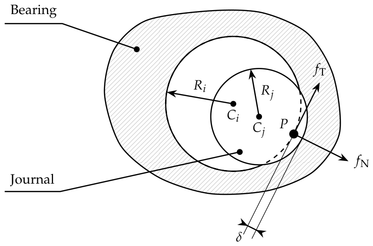
Replacing an ideal revolute joint with another affected by clearance introduces two additional degrees of freedom associated with the relative motion between the bearing and journal centers, C i and C j , as shown in Figure 8. This relative motion is limited by the contact between the body surfaces, which gives rise to contact-impact forces that contribute to the generalized force vector Q in the equations of motion. We describe these interactions by means of the contact model proposed by Lankarani and Nikravesh [12]. This widely used approach represents the normal contact force f N through a nonlinear Hertzian-based contact law,
f N = K δ n 1 + 3 ( 1 e 2 ) 4 δ ˙ δ ˙ ( )
where F N is the normal contact force, K is the contact stiffness coefficient, δ is the penetration depth between the contacting bodies (see Figure 8), and δ ˙ ( ) denotes the initial impact velocity at the beginning of the contact event. The contact stiffness depends on the geometry and material properties of the contacting bodies i and j:
K = 4 3 h i + h j R i R j R i R j 1 / 2 ; with h k = 1 ν k 2 E k , k = i , j
where R is the radius of the body at the contact point, E is its Young modulus, and ν stands for Poisson’s coefficient. The restitution coefficient e governs the energy dissipation during impact. The original contact model was originally intended to describe the interaction between two free spheres, and some adjustments must be performed to use it in a multibody system. In particular, it must be ensured that the ratio between the penetration rate δ and the initial impact velocity δ ˙ ( ) in Equation (17) remains larger than 1 during the separation phase, to avoid the introduction of unrealistic sticking behavior, a solution similar to the arrangement used in [28].
The exponential coefficient in Equation (18) was set to n = 1.5 , a common approach in the clearances literature to describe contact between metal components, e.g., [20]. The coefficient of restitution was tuned to a baseline value e = 0.4 , after comparison between experimental and simulation results. The material properties employed in the contact calculations are summarized in Table 2. The clearance-contact interfaces are formed by F125 steel pins and RG10 bronze bushings, which correspond to the materials used in the experimental test bench.
Ideal joints with bearings were considered to be frictionless. The multibody model, however, introduced friction forces at the interface between the bodies connected by joints affected by clearance. The selected model was the regularized Coulomb friction proposed in [29], which evaluates the magnitude of the tangential force at the contact as
f T = μ f N
where μ is a corrected friction coefficient, computed as a function of the relative velocity v r between the points of the two bodies at the contact, as
μ = 0 if v r v 0 μ 0 v r v 0 / v 1 v 0 if v 0 v r v 1 μ 0 if v r v 1
with v 0 and v 1 threshold velocity values used for regularization, selected as v 0 = 5 · 10 4 m/s and v 1 = 10 3 m/s in this work. Term μ 0 is the dynamic friction coefficient at the contact interface; the results in this work were obtained with μ 0 = 0.05 . The friction force calculated with Equation (19) is subsequently applied at the contact points of the involved bodies in the negative direction of their tangential relative velocity. A friction force of 2.5 N for nonzero velocity was also introduced at the slider guide.
To compare the behavior of the mutibody model with respect to the test bench experiments, the same outputs have to be generated from both systems. The encoder provides the crank angle, which corresponds to the angle coordinate of the crank in the multibody model. The only potential problem is if the angular reference is different for both systems. However, even in this case, the data of one of the systems might be corrected to be consistent with the other system just by adding a constant offset to the whole data series of one of the systems. The accelerometers need more careful consideration: they measure all the accelerations except the gravity. Therefore, this has to be compensated for before making comparisons between multibody simulations and experimental data. In addition, the exact position of each of the accelerometers does not necessarily fit one of the points of the multibody model. To achieve reliable comparisons, the exact position of the accelerometers must be taken into account. In this work, the methodology explained in [30] is used to model the accelerometers. The general position and orientation of the accelerometers can be seen in Figure 9, and a description of the position of the sensors is provided in Table 3. Although the exact position of the accelerometers is not represented in the figure, it was taken into account to generate their virtual representation from the multibody model.

4. Numerical and Experimental Methodology

The developed multibody model and experimental test bench were employed to investigate the dynamic response of the slider–crank mechanism under different operating and clearance conditions. A common experimental matrix was defined for both numerical and experimental studies to assess the influence of clearance location and the effect on simulation results of the contact and friction parameters. The following subsections summarize the numerical setup, the experimental procedure, and the dynamic response analysis methodologies adopted in this work.

4.1. Comparison of Multibody Dynamics Approaches

A preliminary evaluation of the multibody methods presented in Section 3 was carried out to determine their suitability to describe the motion of mechanical systems with clearance in a predictable and reliable way. A 5 s forward-dynamics simulation of the motion of the slider–crank mechanism was simulated using the penalty and R-matrix formulations. The system is initially at rest at an angle θ = π / 3 and it is left to move freely with gravity g = 9.81 m/s2 acting along the negative y-axis. For the purposes of the intended comparison it was not necessary to consider the existence of mechanical clearance, so an ideal mechanism with perfect joints was used as simulation model. The system motion was integrated using a step-size h = 10 4 s and a symplectic Euler integration formula, given by the equations
y k + 1 = y k + h y ˙ k + 1 y ˙ k + 1 = y ˙ k + h y ¨ k
where y stands for the generalized coordinates used in the integration process: q if dependent coordinates are used, and z if independent ones are employed instead.
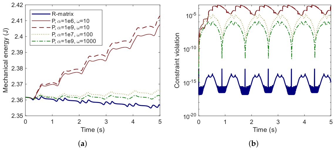
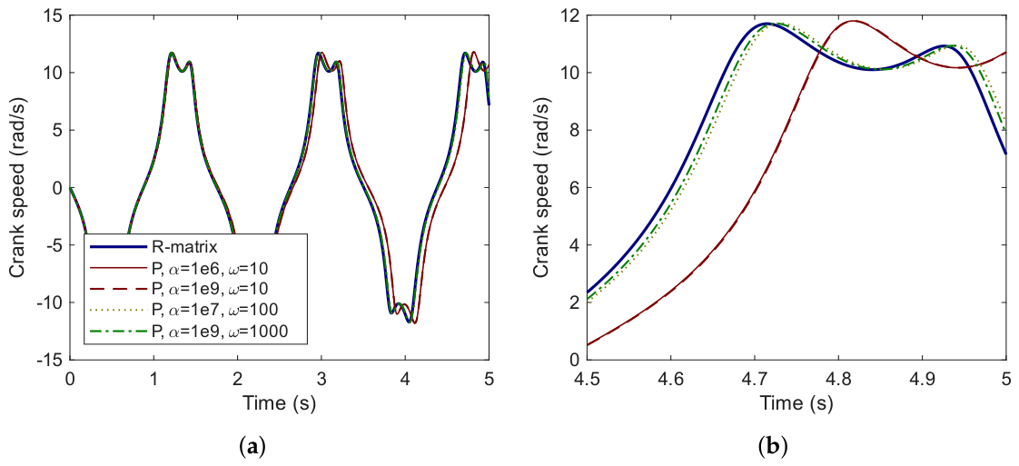
Figure 10 shows the angular velocity of the crank predicted by the R-matrix and the penalty formulations. Different values of the penalty factor α and the stabilization term ω were used for the latter, as shown in the figure. The results show that the selection of these parameters affects the simulation predictions.
Figure 11a shows the mechanical energy of the system during motion to provide further insight into the behavior of the dynamic formulations. In theory, if no friction is considered between the links of the mechanical system, its mechanical energy should remain constant during motion. The results delivered by the R-matrix formulation show a slight energy dissipation, which can be attributed to the error introduced by the numerical integration. The tuning of the parameters of the penalty formulation results in different plots of the mechanical energy. For the particular problem at hand, and the integration step-size selected, α = 10 9 and ω = 1000 deliver the best results. However, it is not guaranteed that this selection will be appropriate if the problem conditions are modified. In the general case, mechanical systems are not conservative, and so it is difficult to know in practice whether the parameter selection introduces additional errors in the results besides those derived from numerical integration. In fact, the simulation fails to converge with these parameters if the integration step-size is set to h = 10 3 s. Figure 11b displays the norm of the constraints term, Φ . Its value should ideally be zero if the kinematic constraints are exactly fulfilled. The R-matrix method brings its value down to machine precision. The penalty approaches, however, allow a violation of the constraints which translates into an internal oscillatory motion of the system elements. In the simulation of a system with clearances, this oscillation is superimposed on those introduced by the impact and contact phenomena at the clearance, making it difficult to distinguish physical behavior from numerical artifacts.
The use of penalty-based methods may be appropriate in applications in which a trade-off between accuracy and computational efficiency is necessary, e.g., real-time simulation of machinery. They can also be used for the simulation of systems with clearance, but this requires a careful tuning of their parameters and a verification of their results. For the test bench presented in this work, formulations that lead to the integration of independent coordinates, such as the R-matrix, avoid the uncertainty that stems from having to tune the formulation parameters and are a preferable choice.

4.2. Test Bench Setup

For the tests reported in this work, the motor controller of the test bench was configured to follow a speed command. In this case, an analog voltage signal of ±10 V provided to the motor corresponds to a commanded speed of ±1000 RPM. Although the motor controller uses the encoder output as feedback, the reciprocating motion of the slider and the system inertia prevent the motor from rotating at a constant speed during the maneuvers. Avoiding completely this behavior would require either adding a heavy flywheel to the crank or using a much more powerful motor. However, since the goal of this test bench is to represent generic industrial mechanisms, this speed variability is not a concern.
The motion transmission from the motor to the crank is done by a V-belt. This system has the advantage of being able to produce continuous power transmission without induced vibrations due to teeth engagement and disengagement, or variable gear ratio, such as chains, gears or timing belts. However, the lack of teeth makes it impossible to guarantee that the motion is synchronous. Therefore, in this test bench, even if the motor is able to achieve the exact commanded speed, the crank might not be rotating at the desired rate. The bench design includes an encoder at the crank axle, which enables the measurement of its angular position independently of the sliding of the belt and the performance of the motor controller.
The first step before conducting a test is to configure the bench to perform it. To avoid undesired phenomena, which could interfere with the dynamic effects caused by clearances, all the setup must be done carefully. The first task is to level the test bench frame by adjusting its threaded legs. Next, the bench must be firmly attached to a solid support. In this case, we are using strong ratchet straps to fix it to a rigid work bench. After that, the proper alignment of the test bench elements and the V-belt tension should be checked. First, the pins of both joints at the end of the slider must be parallel to each other. If they are not completely parallel, the position of the bearings that support the crank shaft can be adjusted to fix this misalignment. The V-belt alignment and its tension can be checked afterwards. The motor can be moved relative to the bench frame to adjust these parameters. These settings are quite robust, so it is not required to check them continuously unless the test bench has been disassembled or if has been subjected to large impacts.
In order to change the clearances of the connecting rod, the affected joints have to be disassembled. Again, proper alignment of all the elements is required for the joints to work as expected. In this case, special care has to be taken when switching from a configuration with no clearances, which uses ball bearings, to a configuration with clearances, which uses journal bearings. The reason is twofold: on the one hand, the thickness of the two types of bearings is different. Therefore, spacer sleeves have to be used to keep proper alignment of the connecting rod. On the other hand, the axial support on both elements is adjusted differently. In both cases we use a nut and a jam nut. When the ball bearing is installed, the nut is tightened against the inner track of the ball bearing. However, when the journal bearing is installed, the nut cannot be tight because there will be relative motion between the nut and the bushing. If the nut is tight in these situation, the bushing would be damaged and the joints would suffer excessive friction.
After installing the joints with the desired configuration, the alignment of the connecting rod must be verified. The misalignment when using ball bearings would produce deformations, increased friction and wear, and variable residual forces. When using journal bearings, the misalignment between the pin and the bushing reduces the effective clearance, or even eliminates it if the misalignment is severe enough. The effective clearance can be checked using a dial indicator and manually shaking the connecting rod vertically without moving the rest of the mechanism.
Once the mechanical setup is ready to perform the tests, the accelerometers must be calibrated. To conduct this calibration, the connecting rod is held horizontally by means of a support. With the test bench in this position, the data acquisition system is started and several seconds are recorded with the mechanism at rest. In this position, accelerometers 1, 4, and 6 are completely horizontal, so they do not measure any acceleration, and accelerometers 2, 3, and 5 are completely vertical upwards (see Figure 9). With this information the offset of the accelerometers can be corrected using the calibration procedure explained in Section 2.3.3.

4.3. Experimental Plan

The experimental plan is geared towards showing the effect of a clearance in joints B, C, or both. In this work, all the tests were done with the y-axis up (see Figure 4), so that gravity acted along its negative direction. Three different rotational speeds were considered for every clearance configuration; the tested scenarios are shown in the experimental matrix of Table 4.
Each of the tests in Table 4 consisted of a 10-second motion of the slider–crank mechanism, with the angular velocity controller of the crank set at the desired speed. For practical reasons, tests with the same mechanical configuration were run consecutively, using the following test structure: at the beginning of a test, the bench is stopped for 2 s, then the first and slowest velocity is commanded to the motor for 10 s, after that the motor is stopped for 2 s, then the second velocity is commanded for 10 s, then stopped for 2 s, after that the third and fastest velocity is commanded, and finally, the motor is stopped for 2 more seconds, and the test bench is shut down. With this structure, three 10-second tests can be performed in 38 s.
During the tests, the six accelerometers, the encoder, and the input signal of the motor were logged with a 100 kHz rate. Each experiment was repeated five times to assess the reproducibility of the results.
The multibody model described in Section Slider–Crank Multibody Model was used to replicate the tests performed with the test bench. The actual test bench is driven by a motor through a V-belt. Modeling and characterizing the motor and transmission would be time-consuming and add complexity and computational cost to the multibody model. Since the goal of this work is to focus on the clearances within the slider–crank mechanism, a PID controller was used to impose the motion of the crank measured during the experimental campaign. This contributes to impose the correct motion of the multibody model while avoiding unnecessary complexity. The step size selected for the simulation of the mechanism was 0.01 ms. This time step matches the sampling frequency of 100 kHz used for logging the experimental data of the test bench, which eases the comparison of test bench and simulation data.

5. Results

This section presents the experimental characterization of the developed slider–crank test bench under different operating conditions and presents a comparison of experimental and simulation results.
The first task conducted on the experimental data was the assessment of the repeatability of the test bench results, comparing the output of the five runs of each test carried out with each bench configuration. The initial position of the test bench was not precisely controlled during the tests, so small differences in position can be expected from one run to another, but the general behavior should be consistent from one test to another.
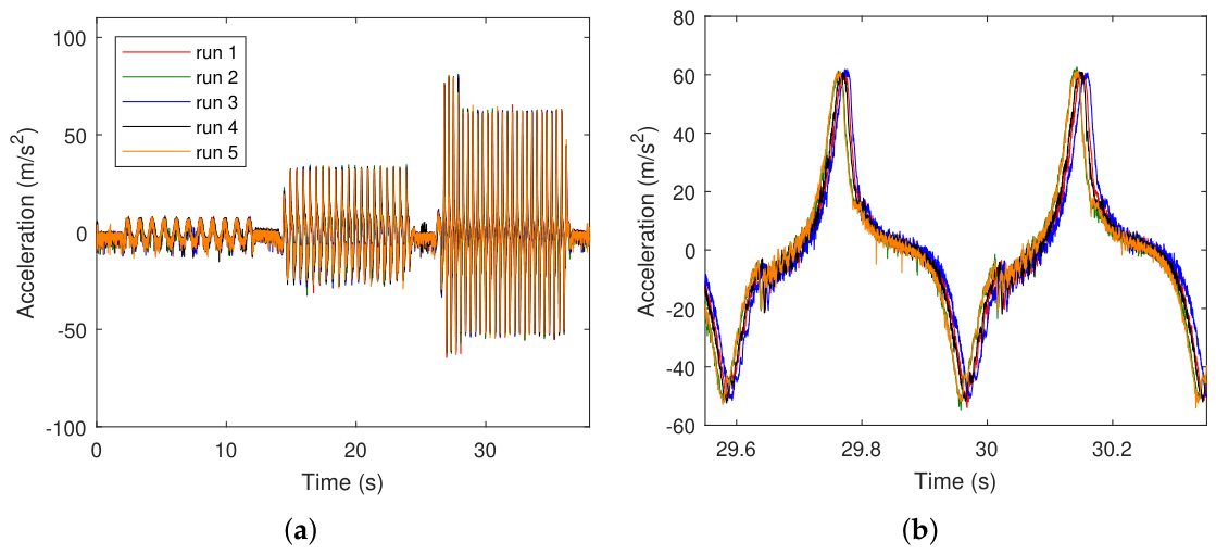
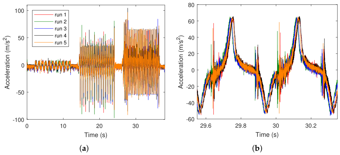
Figure 12 shows the signal provided by accelerometer AC4 during tests with ideal, clearance-free joints. Figure 12a shows the full experiment duration, which included three speed steps corresponding to test IDs 1, 2, and 3 in Table 4. Figure 12b shows a zoom around t = 30 s, when the highest speed was commanded to the mechanism. To assess the repeatability of the test bench, the signals shown in Figure 12b were compared in pairs using the Dynamic Time Warping (DTW) distance, normalized using the difference between the maximum and minimum acceleration of the first maneuver. The maximum difference between recorded signals was obtained between runs 3 and 5, with a normalized distance of 0.296 %. The averaged time shift required to obtain this distance was 0.0139 s, which confirms that the test bench is highly repeatable when no clearances are present.
Figure 13 shows five runs of tests IDs 4, 5, and 6 in Table 4. These repeat the same maneuver as tests 1, 2, and 3, but including a diametral clearance of 0.1 mm introduced at joint C . It can be appreciated that the overall system motion is very similar to that of the ideal mechanism. However, spikes enter the plot when the acceleration is close to zero, showing that the relative motion within the joint with clearance was excited and gave rise to impacts. In this case, the worst match between the maneuvers happened between runs 2 and 4, with a normalized DTW distance of 0.6953 %, and an average time shift of 0.0167 s. This is still a very good match, but the effect of the clearance slightly degrades the repeatability of the test bench.
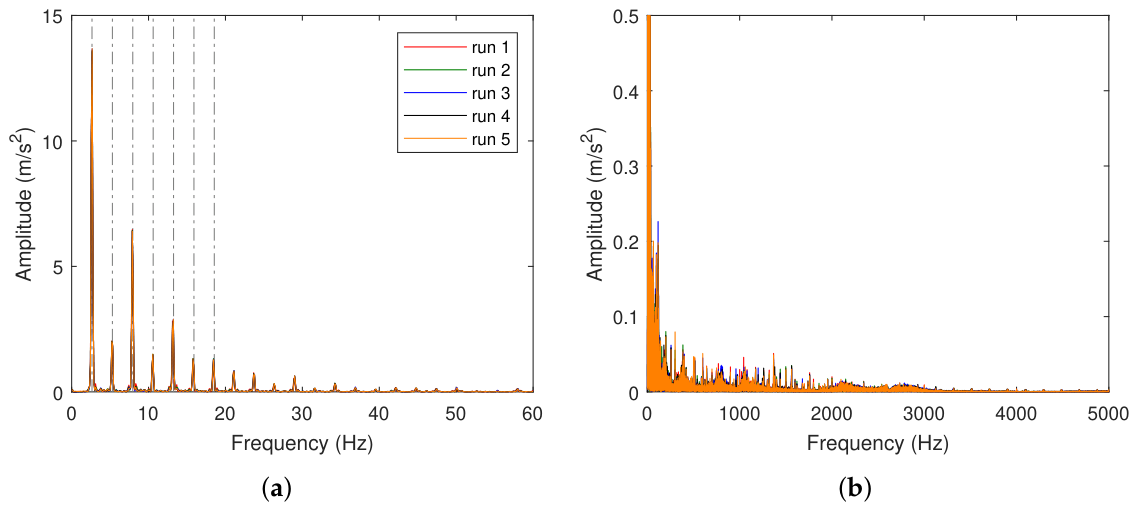
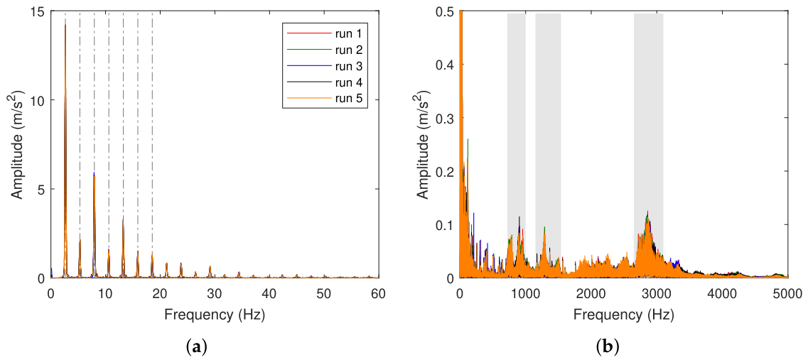
The results in Figure 12 and Figure 13 agree with the expected behavior of the mechanical system. Moreover, the plots and the DTW analysis suggest a good repeatability of the results across different runs of the same maneuver. Nonetheless, a further assessment was performed examining the fast Fourier transform (FFT) of the obtained results. A Hann window was applied to the time-domain signal prior to the FFT to reduce the spectral leakage. Figure 14 shows the FFT analysis for the five repetitions of test ID 3, corresponding to the mechanism without clearances moving at the highest speed. The left plot, Figure 14a, shows the low-frequency components of the FFT, while the right plot in Figure 14b depicts the lower amplitude acceleration components that occur at higher frequencies. Figure 15 is a counterpart to Figure 14 that contains the FFT of the signal from accelerometer 4 obtained with a 0.1 mm clearance at joint C .
Figure 14 and Figure 15 confirm that the test bench is able to deliver reproducible results, with all the runs of each tests resulting in similar time-histories and FFT transforms. Moreover, the inspection of the low-frequency plots for test IDs 3 and 6 reveals that the general motion of the test bench is very similar in both cases. The small-amplitude components at higher frequencies, conversely, show the differences caused by clearance, with impacts giving rise to larger amplitudes at high frequencies, but specially around 1000 Hz and 3000 Hz, as highlighted by the shadowed bands in Figure 15b. These results confirm that FFT is a suitable way to identify the existence of clearance from accelerometer readings.
The comparison between experimental and simulation results is motivated by the assessment of the capability of the multibody results to capture the modification of the ideal system behavior introduced by joint clearances. As explained in Section 4.3, the forward-dynamics simulations were guided by encoder readings retrieved from the physical bench during experimental tests, and this reference tracked by means of a PID controller. In order to determine the ability of the numerical simulation to identify the presence of clearance, the same input was fed to forward-dynamics simulation runs of a model of the slider–crank mechanism with and without clearance.
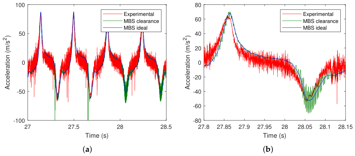
Figure 16 compares the accelerations delivered by two multibody models, one with ideal joints, and another with a 0.1 mm diametral clearance at joint C , in terms of their ability to reproduce the system behavior registered in experiments. In both cases, the crank angle from the fifth repetition of test ID 6 was used as input. The numerical simulations were performed using the R-matrix method from Section 3, integrated with a symplectic Euler formula and a step-size h = 0.01 ms. Results from accelerometer AC6, mounted horizontally on the slider, are shown in Figure 16. The experimental results reflect the relative motion between the pin and the bushing at the slider joint when the slider acceleration reverses its sign. The clearance at the joint in the experimental setup causes a loss of contact between the affected bodies and a subsequent impact when contact is re-established, which translates into spikes in the accelerometer readings. The accelerations predicted by the multibody simulation reproduce this behavior when the clearance between the connecting rod and the slider is considered in the model. The first two cycles in Figure 16a show high-amplitude impacts at the right instants in time. The following cycles do not show impacts, but high-frequency oscillations are induced after the points where the relative motion between the pin and the bushing happens. This oscillation can be seen in more detail in Figure 16b. These effects cannot be observed if the multibody model only includes ideal joints. Although it is driven by the exact same signal, the ideal representation is unable to predict impacts or vibrations caused by clearance. This confirms the necessity of modeling the defect to obtain accurate acceleration predictions and, more importantly, rules out the possibility that spikes in the simulated acceleration are caused by the velocity controller. It could be argued that, because the simulation input is the crank angle from an experiment in which joint C was subjected to clearance, the impacts caused by the defect could be entering the numerical simulation through sudden variations in the recorded angle, but the results shown in Figure 16 exclude this possibility.

6. Discussion

The experimental results confirmed that the developed test bench is capable of generating consistent and repeatable mechanical behavior under controlled operating conditions. The observed acceleration signals exhibit the expected dynamic characteristics of a slider–crank mechanism subjected to clearance. These characteristics establish the proposed test bench as a suitable experimental asset for the generation of benchmark datasets for hybrid model-based and data-driven clearance characterization.
The results also confirmed the ability of multibody system dynamics simulations to capture the fundamental behavior of the test bench when clearance is introduced in its joints. Forward-dynamics simulation replicates the test bench motion for the same input command. In addition, it is possible, after adjusting the contact and friction model properties, to obtain simulation results that predict the existence of impacts derived from clearance at the same instants as in the experimental setup. The characterization of these impacts, however, remains an open issue and will require further developments regarding the contact and friction models. Accelerometer readings showed that clearance-induced impacts result in acceleration peaks that quickly reach their maximum value and subside in a few milliseconds. Simulation reproduces this behavior at some points in the time-history with the contact model used in this research, while at others the acceleration oscillates in time without dissipating, a behavior also reported in other works, e.g., [20]. The evaluation of models that describe contact interactions between cylinders [31,32] to characterize peak accelerations based on physical parameters will be an upcoming task. Accurately determining the energy dissipation remains an open task, as the employed models must be able to account for damping both after an impact and during sustained contact. To enable the use of simulation-generated synthetic data in hybrid model-based and data-driven approaches to characterize clearance, it is necessary that not only the occurrence in time of impact phenomena is appropriately represented. Simulation results should also capture to a certain degree of accuracy the amplitude and nature of the acceleration changes caused by clearance. Neural networks could be trained exclusively with experimental results from the bench. This, however, would be an expensive and time-consuming solution. Such experimental data can be augmented with simulation results, but these would need to be consistent with the experiments in terms, for instance, of the resulting FFT. A similar issue affects multibody models if these are to be used to describe the plant in a Kalman filter.
It must also be noted that the velocity control used to select the operation point of the test bench poses an additional difficulty from the point of view of numerical simulation. The velocity controller used by the bench motor is not explicitly known. In order to replicate the obtained motion in the simulation, an angular velocity controller must be applied to the motion of the crank. There exist the possibility that this control introduces dynamics effects in the system that do not exist in the test bench. Employing a torque control command for the bench motor can be used to remove this uncertainty. Instead of regulating the angular velocity of the crank, experiments can be conducted specifying an input torque to the motor and then releasing the mechanism after it reaches a certain velocity. This approach will be the basis of an upcoming experimental plan for the mechanism.

7. Conclusions

This work presented the development of a configurable slider–crank experimental platform for the investigation of mechanical clearances under controlled and repeatable operating conditions. The developed test bench enables the on-purpose introduction of radial clearances at different joints of the mechanism while allowing systematic variation of operating parameters such as rotational speed and mechanism orientation. A corresponding multibody model was also developed to support the design and analysis of the platform, as well as to help identify the sources of the differences between simulation and experimental results.
The preliminary comparison of the simulation results confirmed that formulations based on independent coordinates, such as the R-matrix method, are preferable to penalty-based multibody formulations when dealing with mechanical systems subjected to clearance. The uncertainty associated with the tuning of the parameters used to remove constraint drift in penalty-based methods, as well as the introduction of high-frequency oscillations in the system dynamics are avoided by formulations that use minimal coordinates.
An experimental characterization campaign was conducted to evaluate the dynamic response of the developed system through acceleration measurements. The obtained results are consistent with the expected dynamic behavior of clearance-affected multibody systems and confirm the capability of the platform to capture clearance-induced vibration phenomena. The repeatability analysis performed through repeated experimental measurements showed acceptable variations for all investigated conditions, indicating good measurement consistency and robustness of the experimental setup. Furthermore, the frequency-domain analysis revealed identifiable changes in spectral content associated with the presence of clearance, demonstrating the ability of the platform to generate informative vibration signatures suitable for detailed dynamic investigations.
Overall, the combination of configurability, measurement repeatability, and sensitivity to clearance variations confirms the suitability of the proposed platform for experimental studies of mechanical clearances. The developed infrastructure provides a reliable basis for the generation of benchmark datasets and establishes a valuable framework for future research on vibration-based clearance identification, condition monitoring, and predictive maintenance methodologies. The analysis of the results also confirmed the necessity of further research to determine the appropriate simulation modeling approaches to describe the frequency response of the system, a requirement for the use of synthetic data in hybrid data-augmented solutions for the prediction and characterization of mechanical clearance.

Author Contributions

Model development, Experiments, Data curation, Writing—original draft, Z.H.M.; Experiments, Visualization, Conceptualization, Supervision, E.S.; Multibody system model setup, Validation, Visualization, M.L.-L.; Visualization, Conceptualization, Model development, A.J.R.; Conceptualization, Funding acquisition, Supervision, Validation, M.Á.N.; Conceptualization, Funding acquisition, Project administration, Validation, Writing—review and editing, Resources, Supervision, F.G. All authors have read and agreed to the published version of the manuscript.

Funding

This research was funded by MICIU/AEI/10.13039/501100011033 and ERDF, EU, through grant PID2022-139832NB-I00, and by the Government of Galicia through grant ED431C 2023/01.

Data Availability Statement

The datasets presented in this article are not readily available because the data are part of an ongoing study. Requests to access the datasets should be directed to zeeshan.malik@udc.es.

Conflicts of Interest

The authors declare no conflicts of interest.

References

  1. Uicker, J.J.; Pennok, G.R.; Shigley, J.E. Theory of Machines and Mechanisms, 6th ed.; Cambridge University Press: Cambridge, UK, 2023. [Google Scholar]
  2. Tian, Q.; Flores, P.; Lankarani, H.M. A comprehensive survey of the analytical, numerical and experimental methodologies for dynamics of multibody mechanical systems with clearance or imperfect joints. Mech. Mach. Theory 2018, 122, 1–57. [Google Scholar] [CrossRef] [Scilit]
  3. Flores, P.; Ambrósio, J.; Claro, J.C.P.; Lankarani, H.M. Translational joints with clearance in rigid multibody systems. J. Comput. Nonlinear Dyn. 2007, 3, 011007. [Google Scholar] [CrossRef] [Scilit]
  4. Flores, P.; Leine, R.; Glocker, C. Modeling and analysis of planar rigid multibody systems with translational clearance joints based on the non-smooth dynamics approach. Multibody Syst. Dyn. 2009, 23, 165–190. [Google Scholar] [CrossRef] [Scilit]
  5. Wilson, R.; Fawcett, J. Dynamics of the slider-crank mechanism with clearance in the sliding bearing. Mech. Mach. Theory 1974, 9, 61–80. [Google Scholar] [CrossRef] [Scilit]
  6. Farahanchi, F.; Shaw, S. Chaotic and periodic dynamics of a slider-crank mechanism with slider clearance. J. Sound Vib. 1994, 177, 307–324. [Google Scholar] [CrossRef] [Scilit]
  7. Erkaya, S.; Uzmay, I. Experimental investigation of joint clearance effects on the dynamics of a slider-crank mechanism. Multibody Syst. Dyn. 2010, 24, 81–102. [Google Scholar] [CrossRef] [Scilit]
  8. Megahed, S.; Haroun, A. Analysis of the dynamic behavioral performance of mechanical systems with multi–clearance joints. J. Comput. Nonlinear Dyn. 2011, 7, 011002. [Google Scholar] [CrossRef] [Scilit]
  9. Muvengei, O.; Kihiu, J.; Ikua, B. Numerical study of parametric effects on the dynamic response of planar multi-body systems with differently located frictionless revolute clearance joints. Mech. Mach. Theory 2012, 53, 30–49. [Google Scholar] [CrossRef] [Scilit]
  10. Muvengei, O.; Kihiu, J.; Ikua, B. Dynamic analysis of planar rigid-body mechanical systems with two-clearance revolute joints. Nonlinear Dyn. 2013, 73, 259–273. [Google Scholar] [CrossRef] [Scilit]
  11. Hunt, K.H.; Crossley, F.R.E. Coefficient of restitution interpreted as damping in vibroimpact. J. Appl. Mech. 1975, 42, 440–445. [Google Scholar] [CrossRef] [Scilit]
  12. Lankarani, H.M.; Nikravesh, P.E. A contact force model with hysteresis damping for impact analysis of multibody systems. J. Mech. Des. 1990, 112, 369–376. [Google Scholar] [CrossRef] [Scilit]
  13. Flores, P. A parametric study on the dynamic response of planar multibody systems with multiple clearance joints. Nonlinear Dyn. 2010, 61, 633–653. [Google Scholar] [CrossRef] [Scilit]
  14. Marques, F.; Isaac, F.; Dourado, N.; Flores, P. An enhanced formulation to model spatial revolute joints with radial and axial clearances. Mech. Mach. Theory 2017, 116, 123–144. [Google Scholar] [CrossRef] [Scilit]
  15. Naya, M.Á.; Sanjurjo, E.; Rodríguez, A.J.; Cuadrado, J. Kalman filters based on multibody models: Linking simulation and real world. A comprehensive review. Multibody Syst. Dyn. 2023, 58, 479–521. [Google Scholar] [CrossRef] [Scilit]
  16. Rodríguez, A.J.; Sanjurjo, E.; Cabello, M.; López-Lombardero, M.; Díaz, P.; González, F.; Naya, M.A. Development of Kalman filter approaches for the monitoring of mechanical clearances. In Proceedings of the Mechanism and Machine Theory Symposium, Guimarães, Portugal, 26–28 June 2024. [Google Scholar]
  17. Rodríguez, A.J.; Sanjurjo, E.; López-Lombardero, M.; Cabello, M.; González, F.; Naya, M.A. A novel Kalman filter approach for clearances estimation. In Proceedings of the 12th ECCOMAS Thematic Conference on Multibody Dynamics, Innsbruck, Austria, 13–18 July 2025. [Google Scholar]
  18. Sanjurjo, E.; Rodríguez, A.J.; López-Lombardero, M.; Cabello, M.; González, F.; Naya, M.A. Mechanical clearances estimation by means of unscented Kalman filtering. In Proceedings of the 8th Joint International Conference on Multibody System Dynamics (IMSD), Sevilla, Spain, 16–19 June 2026. [Google Scholar]
  19. Nguyen, T.V.; Rodríguez, A.J.; González, F.; Mikkola, A.; Kim, J.G.; Orzechowski, G. Clearance size detection based on deep neural networks without feature extraction. Multibody Syst. Dyn. 2026, 67, 1143–1170. [Google Scholar] [CrossRef] [Scilit]
  20. Flores, P.; Koshy, C.S.; Lankarani, H.M.; Ambrósio, J.; Claro, J.C.P. Numerical and experimental investigation on multibody systems with revolute clearance joints. Nonlinear Dyn. 2011, 65, 383–398. [Google Scholar] [CrossRef] [Scilit]
  21. Xu, L.X.; Han, Y.C.; Dong, Q.B.; Jia, H.L. An approach for modelling a clearance revolute joint with a constantly updating wear profile in a multibody system: Simulation and experiment. Multibody Syst. Dyn. 2019, 45, 457–478. [Google Scholar] [CrossRef] [Scilit]
  22. García de Jalón, J.; Bayo, E. Kinematic and Dynamic Simulation of Multibody Systems: The Real-Time Challenge; Springer: New York, NY, USA, 1994. [Google Scholar] [CrossRef] [Scilit]
  23. García de Jalón, J.; Gutiérrez-López, M.D. Multibody dynamics with redundant constraints and singular mass matrix: Existence, uniqueness, and determination of solutions for accelerations and constraint forces. Multibody Syst. Dyn. 2013, 30, 311–341. [Google Scholar] [CrossRef] [Scilit]
  24. Bayo, E.; Garcia De Jalón, J.; Serna, M.A. A modified Lagrangian formulation for the dynamic analysis of constrained mechanical systems. Comput. Methods Appl. Mech. Eng. 1988, 71, 183–195. [Google Scholar] [CrossRef] [Scilit]
  25. Flores, P.; Machado, M.; Seabra, E.; Tavares da Silva, M. A parametric study on the Baumgarte stabilization method for forward dynamics of constrained multibody systems. J. Comput. Nonlinear Dyn. 2011, 6, 011019. [Google Scholar] [CrossRef] [Scilit]
  26. González, F.; Dopico, D.; Pastorino, R.; Cuadrado, J. Behaviour of augmented Lagrangian and Hamiltonian methods for multibody dynamics in the proximity of singular configurations. Nonlinear Dyn. 2016, 85, 1491–1508. [Google Scholar] [CrossRef] [Scilit]
  27. Bayo, E.; Avello, A. Singularity-free augmented Lagrangian algorithms for constrained multibody dynamics. Nonlinear Dyn. 1994, 5, 209–231. [Google Scholar] [CrossRef] [Scilit]
  28. Pombo, J.; Ambrósio, J.; Silva, M. A new wheel–rail contact model for railway dynamics. Veh. Syst. Dyn. 2007, 45, 165–189. [Google Scholar] [CrossRef] [Scilit]
  29. Ambrósio, J.A.C. Impact of rigid and flexible multibody systems: Deformation description and contact models. In Virtual Nonlinear Multibody Systems; Shiehlen, W., Valásek, M., Eds.; Springer: Dordrecht, The Netherlands, 2003; pp. 57–81. [Google Scholar] [CrossRef] [Scilit]
  30. Sanjurjo, E.; Dopico, D.; Luaces, A.; Naya, M.Á. State and force observers based on multibody models and the indirect Kalman filter. Mech. Syst. Signal Process. 2018, 106, 210–228. [Google Scholar] [CrossRef] [Scilit]
  31. Pereira, C.; Ramalho, A.; Ambrosio, J. Applicability domain of internal cylindrical contact force models. Mech. Mach. Theory 2014, 78, 141–157. [Google Scholar] [CrossRef] [Scilit]
  32. Hu, J.; Gao, F.; Liu, X.; Wei, Y. An elasto-plastic contact model for conformal contacts between cylinders. Proc. Inst. Mech. Eng. Part J. Eng. Tribol. 2019, 234, 1837–1845. [Google Scholar] [CrossRef] [Scilit]
Figure 1. CAD model (left) and experimental test bench (right) of the configurable slider–crank mechanism. Bodies 1–3 denote the crank, connecting rod, and slider, respectively. Configurable clearances can be introduced at the crank–connecting rod and connecting rod–slider joints.
Machines 14 01073 g001
Figure 2. Kinematic representation of the slider–crank mechanism. Radial clearances can be introduced at joints B and C , while a two-sided clearance can be considered at the slider–guide interface. Point A denotes the fixed crank pivot. The offset d off represents the distance between the connecting rod–slider revolute joint C and the slider reference point C s .
Machines 14 01073 g002
Figure 3. Position of the center of mass ( G ) of the bodies in the slider–crank linkage under study. Distance x G between the origin of each body and G is shown under column x G in Table 1. (a) shows the center of mass of the crank, (b) shows the center of mass of the connecting rod, and (c) shows the center of mass of the slider.
Machines 14 01073 g003
Figure 4. Overview of the experimental slider–crank test bench, indicating the main mechanical components, actuation system, encoder location, and reference coordinate system used in the experimental investigations.
Machines 14 01073 g004
Figure 5. Configurable revolute-joint arrangements used in the test bench: (A) Nominal configuration employing a deep-groove ball bearing; (B) clearance configuration using interchangeable bushings to provide prescribed radial clearance values.
Machines 14 01073 g005
Figure 6. Configuration and orientation of the six uniaxial accelerometers installed on the experimental test bench. Arrows indicate the positive sensitivity direction of each sensor.
Machines 14 01073 g006
Figure 7. Multibody representation of the slider–crank mechanism including radial clearances at the crank–connecting rod joint ( B B ) and the connecting rod–slider joint ( C C ). The contact interactions at both clearance interfaces are represented through contact forces f c B , f c B , f c C , and f c C . Offset d off denotes the vertical distance between point C and the slider guide center line.
Machines 14 01073 g007
Figure 8. Diagram of a planar revolute joint affected by radial clearance.
Machines 14 01073 g008
Figure 9. Configuration and orientation of the six accelerometers incorporated into the multibody model. The arrangement reproduces the location and orientation of the accelerometers installed on the experimental test bench.
Machines 14 01073 g009
Figure 10. Comparison between R-matrix and penalty (P) formulations: Free motion of the slider-crank mechanism under gravity effects. In (a) the angular velocity of the crank in a 5 s maneuver is shown, while (b) provides more detail of the last 0.5 s of the same data.
Machines 14 01073 g010
Figure 11. Comparison between R-matrix and penalty (P) formulations: Free motion of the slider-crank mechanism under gravity effects. (a) shows the mechanical energy and (b) shows the configuration-level constraints violation.
Machines 14 01073 g011
Figure 12. Measurements of the accelerometer AC4 with no clearances in the mechanism. The test was repeated five times in the same conditions. (a) shows five different runs of tests IDs 1, 2, and 3. (b) zooms in around t = 30 s, which corresponds to the highest commanded speed (test ID 3).
Machines 14 01073 g012
Figure 13. Measurements of accelerometer AC4 with a diametral clearance of 0.1 mm at joint C . The test was repeated 5 times in the same conditions. (a) shows the five runs of tests IDs 4, 5, and 6. (b) provides a time zoom at around second 30, which corresponds to the highest speed commanded (test ID 6).
Machines 14 01073 g013
Figure 14. FFT of accelerometer AC4 signal in test ID 3 (the highest speed studied in this work, without joint clearance). The signal has been Hann-windowed to minimize spectral leakage. The test was repeated five times in the same conditions. (a) shows the low-frequency components, with the vertical dashed lines indicating the rotational frequency of the crank and its six first harmonics, and (b) shows the frequencies up to 5000 Hz.
Machines 14 01073 g014
Figure 15. FFT of accelerometer AC4 signal in test ID 6 (the highest speed studied in this work, with a 0.1 mm diametral clearance at joint C ). The signal has been Hann-windowed to minimize spectral leakage. The test was repeated 5 times in the same conditions. (a) shows the low-frequency components with the vertical dashed lines indicating the rotational frequency of the crank and its six first harmonics, and (b) shows the frequencies up to 5000 Hz. The shadowed areas indicate the frequency bands in which the increase of spectral activity is more relevant with respect to the ideal case.
Machines 14 01073 g015
Figure 16. Comparison of measurements from accelerometer AC6 from test ID 6 with a 0.1 mm clearance at joint C , the multibody simulation with the same clearance (MBS clearance), and the multibody simulation with ideal joints (MBS ideal). (a) shows four full crank revolutions, while (b) is a time zoom showing only one.
Machines 14 01073 g016
Table 1. Mechanical properties of the slider–crank mechanism components.
Mass (kg)Length (m) x G (m)Inertia ( kg/m 2 )
Crank ( A B ) 5.72 0.12 0.0115 0.0293
Connecting rod ( B C ) 3.55 0.60 0.3000 0.1970
Slider ( Cs ) 1.97 0.05 0.0040 0.0025
Table 2. Material properties of the revolute-joint clearance components.
PinBushing
Elastic modulus (GPa)21090
Poisson’s ratio 0.30 0.34
Mass density (kg/m3)78508700
Table 3. Description of the acceleration measurements considered in the investigations. Sensor IDs correspond to the locations shown in Figure 9.
IDBodyAcceleration Measurement
AC1Connecting rodLongitudinal to the connecting rod at joint B
AC2Connecting rodPerpendicular direction of the connecting rod at joint B
AC3Connecting rodPerpendicular to the connecting rod at joint C
AC4Connecting rodLongitudinal direction of the connecting rod at joint C
AC5SliderVertical acceleration of the slider
AC6SliderHorizontal acceleration of the slider
Table 4. Investigation matrix considered in the numerical and experimental studies.
IDClearance at Joint B (mm)Clearance at Joint C (mm)Speed (rpm)
100250
200500
300750
400.1250
500.1500
600.1750
70.10250
80.10500
90.10750
100.10.1250
110.10.1500
120.10.1750
Disclaimer/Publisher’s Note: The statements, opinions and data contained in all publications are solely those of the individual author(s) and contributor(s) and not of MDPI and/or the editor(s). MDPI and/or the editor(s) disclaim responsibility for any injury to people or property resulting from any ideas, methods, instructions or products referred to in the content.