Article

Ring-Coupled Nonlinear Adaptive PI Coordinated Control Strategy for Multi-PMSMs with Event-Triggered Mechanism


1
Key Laboratory of Metallurgical Equipment and Control Technology of Ministry of Education, Wuhan University of Science and Technology, Wuhan 430081, China
2
Hubei Key Laboratory of Mechanical Transmission and Manufacturing Engineering, Wuhan University of Science and Technology, Wuhan 430081, China
3
Guangdong Zhongnan Iron and Steel Co., Ltd., Shaoguan 512122, China
4
School of Mechanical and Electrical Engineering, Guangzhou University, Guangzhou 510006, China
*
Author to whom correspondence should be addressed.
Machines 2026, 14(8), 869; https://doi.org/10.3390/machines14080869
Submission received: 8 June 2026 / Revised: 24 July 2026 / Accepted: 28 July 2026 / Published: 1 August 2026
(This article belongs to the Section Automation and Control Systems)

Abstract

For multi-permanent magnet synchronous motors (multi-PMSMs) with nonlinearity and uncertainty, an event-triggered nonlinear adaptive PI control is proposed. To enhance the synchronization of multi-PMSMs, a coordinated control strategy is implemented. On the basis of this, a nonlinear adaptive PI control is proposed to address the tracking of the speed of the PMSMs, and the uncertainty signal is estimated by designing an adaptive law. Furthermore, an adaptive event-triggered control mechanism is presented to update control signals in real time, reducing communication resource consumption while maintaining ideal performance. Simulation results on a four-PMSM ring-coupled system demonstrate that the proposed event-triggered mechanism reduces the number of control signal transmissions by up to 92.1% compared with time-triggered sampling, while maintaining comparable control accuracy.

1. Introduction

PMSM is a type of synchronous motor that generates a synchronous rotating magnetic field through permanent magnet excitation. They possess many remarkable advantages such as high power density, superior efficiency, high starting torque, and excellent power performance, making their widespread application in electric vehicles, industrial robots, medical care, and other fields [1,2,3,4]. The widespread adoption of linear PI control in PMSMs stems from its straightforward structure and convenient implementation [5,6,7]. Nevertheless, conventional linear PI control exhibits considerable vulnerability to both load variations and unforeseen perturbations within highly nonlinear systems, which consequently restricts its ability to achieve the stringent precision requirements of PMSM [8,9,10].
In order to pursue high performance in terms of tracking accuracy and real-time response, as well as to improve system robustness, a number of advanced control methods was proposed in recent years, such as adaptive control [11,12], model predictive control [13,14], neural network control [15,16], and fuzzy logic control [17,18]. In [15], a weight-adaptive neural network was designed based on Lyapunov analysis for the online approximation of lumped disturbances. In [13], an improvement to the control accuracy of PMSM was proposed. This enhancement entailed integrating a predictive compensation mechanism into the PMSM system. In [11], an adaptive terminal sliding mode controller was applied to estimate the uncertainty of PMSM. In [17], a robust control method was proposed to enhance system stability, which can handle the uncertainty and external disturbances of PMSM. Compared with traditional linear PI control methods. Theoretically, these methods effectively solve the nonlinear problems in PMSM. But these methods greatly increase the complexity of PMSM control, which is difficult to implement in practical applications. Therefore, it is worth paying attention to researching a practical control method to improve the control effect of PMSM in actual applications.
As industrial technology continues to advance, PMSM often needs to work in collaboration to satisfy work requirements. The coordinated control of multi-PMSM systems has been extensively investigated by researchers. The main control methods currently used for multi-PMSMs include cross-coupled control, virtual spindle control and ring-coupled control [19,20,21,22,23,24,25,26]. Ring-coupled control is a widely adopted control method in modern multi-PMSMs due to its strong system synchronization and anti-interference capabilities [23,24,25,26,27]. In [23], to enhance the multi-PMSMs’ performance, an improved active disturbance rejection ring-coupled controller was presented. This approach aims to boost synchronization performance and strengthen robustness against disturbances in multi-PMSM applications. In [24], an innovative control strategy involving a ring-coupled current compensation module was proposed. In [25], a self-coupled PID ring-coupled control strategy was proposed with a view to with the goal of improving the system’s robustness against interference. In [26], a fuzzy modeling approach combined with event-triggered control is proposed to achieve global stability control of grid-connected PMSMs under random disturbances. In [27], an adaptive sliding mode control combined with the ring-coupling structure has effectively synchronized multiple PMSMs. These control methods combine ring-coupled control strategies with modern control algorithms, which significantly improve the cooperative control capabilities of multi-PMSMs and ensure stable convergence of the system.
In recent years, event-triggered mechanisms have received widespread attention. By designing trigger thresholds that reduce unnecessary signal transmission, the system only activates when these thresholds are met, saving communication resources and reducing the communication load [27,28,29,30,31]. In [27], a higher-order event-triggered mechanism was designed for a nonlinear system to update the actual control input. In [28], a novel approach to the implementation of a sliding mode speed control scheme was proposed, with particular relevance to PMSM. In [29], a novel event-triggered combined terminal sliding mode control strategy was presented for PMSM speed regulation. In [31], an event-triggered fixed-time control strategy was proposed to effectively achieve load tracking and motor synchronization. Undoubtedly, all these strategies can effectively save communication resources, but this may come at the cost of reduced convergence efficiency. Therefore, it is necessary to design an efficient event-triggered control strategy that can ensure the system converges rapidly while reducing the communication pressure on it.
In consideration of the aforementioned analysis, this work designs an adaptive event-triggered ring-coupled nonlinear adaptive PI control for multi-PMSMs with strong nonlinearity. The main contributions of this work are outlined below:
  • A nonlinear adaptive PI control method is proposed that combines the advantages of traditional PI control and adaptive control. By designing adaptive parameters, the controller can be updated in real-time, which effectively reduces the difficulty of adjusting control parameters. This control method can effectively track and synchronize the speed of a group of electric motors, and maintain control accuracy and stability when faced with load changes and unknown disturbances.
  • An adaptive event triggering mechanism based on the ring-coupled control strategy for multi-PMSMs is designed, which adapts the time triggering threshold according to the actual operating status of the PMSM. This control strategy avoids unnecessary signal updates, reducing the communication resource consumption of the multi-PMSMs while ensuring system convergence efficiency.
The remaining sections are as follows: The mathematical model of the system is developed in Section 2. Section 3 designs the control scheme and analyzes its stability. In Section 4, we provide simulation-based evidence to confirm the effectiveness of our approach. Finally, we present conclusions in Section 5.

2. System Description and Preliminaries

2.1. System Description

Assuming three-phase symmetry, ignoring hysteresis loss and core saturation, according to the principle of magnetic momentum equivalence in the system, the voltage of the PMSM in the rotating two-phase system is given by the following equation
u d = R m i d + L d d i d d t ω e ψ q u q = R m i q + L q d i q d t ω e ψ d
where u d and u q are d , q a x i s voltages, respectively. i d and i q are currents. R m is resistance. L d = L q are inductance. ψ d and ψ q are flux linkages. ω e is the rotor electrical angular velocity.
The equation of the flux linkage stator can be described as follows
ψ d = L d i d + ψ f ψ q = L q i q
where ψ f is the flux linkage.
The equation of the relationship between the surface-mounted PMSMs electromagnetic torque T e and the stator current of the d , q a x i s can be described as
T e = 3 2 n p i q ( L d L q ) i d + ψ f = 3 2 n p i q ψ f
where n f is pole pairs.
Furthermore, the mechanical dynamics equation of the PMSM can be written as follows
J d ω m d t = T e T L B m ω m
where ω m is the rotor mechanical angular velocity, J is the inertia, T L is the motors load torque, B m is the motor viscous damping.
Taking T e into (4), we can obtain the following:
ω ˙ ( t ) = B m J ω ( t ) + 3 n p ψ f 2 J i q ( t ) T L J
Then, the equation of i-th PMSM can be expressed as
ω ˙ i ( t ) = Φ i ω i ( t ) + H i i q , i ( t ) + N i T L , i
where Φ i = B m ( i ) J i < 0 , H i = 3 n p ( i ) ψ f ( i ) 2 J i > 0 , N i = 1 J i < 0 .
To reflect the impact of parameter uncertainties and external load disturbances, the system parameters are considered to deviate from their rated values. Equation (6) can be reformulated as
ω ˙ i ( t ) =   ( Φ ¯ i + Δ Φ i ) ω i ( t ) + H i i q , i ( t ) + N i T L , i + i =   Φ ¯ i ω i ( t ) + H i i q , i ( t ) + Z i ( t )
where Φ ¯ i is the nominal values of Φ i , Δ Φ i denote the uncertainties, Z i ( t ) = Δ Φ i ω i ( t ) + N i T L , i + i , The parameter i denotes uncertainty from non-ideal transient control and unmodeled dynamics. As such, Z i ( t ) is the part of the system attributed to this uncertainty.

2.2. Preliminaries

Lemma 1
([4]). For x R and y R , existing a > 0 , b > 0 , and c > 0 , one has
x a y b a a + b c x a + b + b a + b c a b x a + b
Lemma 2
([16]). For b 1 R and b 2 R , one has
b 1 b 2 m c c b 1 c + 1 d m d b 2 d
where c > 1 , d > 1 , and it satisfies ( c 1 ) ( d 1 ) = 1 .
Lemma 3
([27]). For a 1 R and a 2 > 0 , one has
0 a 1 a 1 tanh ( a 1 a 2 ) 0.2785 a 2
Lemma 4
([30]). For semi-positively determinable derivative function V t , existing constants τ 1 > 0 and τ 2 > 0 , where the derivative satisfies the relationship V ˙ < τ 1 V + τ 2 , one has
0 V t 1 e τ 1 t τ 2 τ 1 + V 0 e τ 1 t

3. Controller Design and Stability Analysis

3.1. Ring-Coupled Control Strategy Design

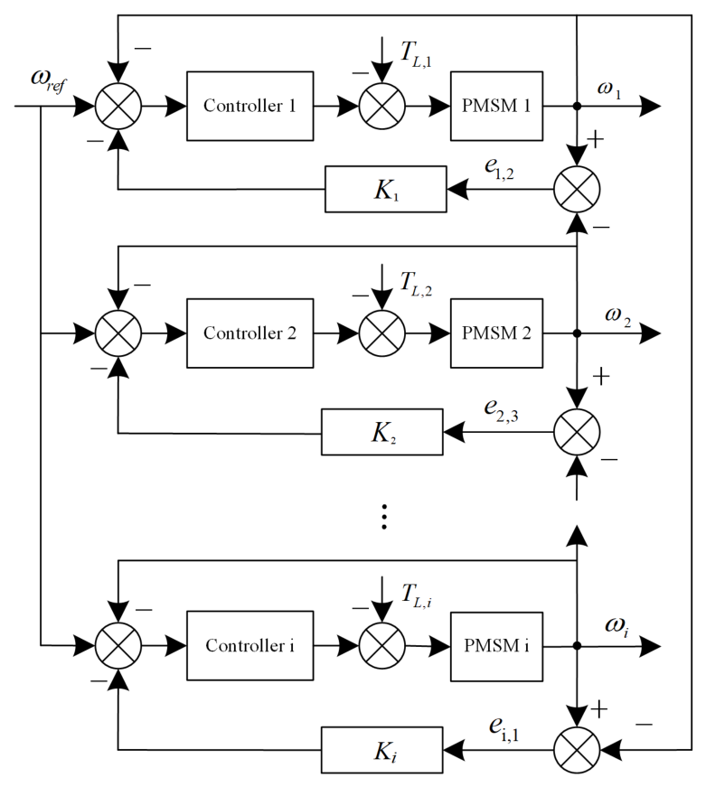
In multi-PMSM systems with a ring-coupled configuration, the control strategy focuses solely on the synchronization error between each motor’s real speed and the reference synchronous speed. The corresponding control structure is depicted in Figure 1.
The definition of the speed tracking error is given by
e i , r e f ( t ) = ω i ( t ) ω i , r e f ( t ) i = 1 , 2 , , n
where e i , r e f ( t ) is the i-th PMSM tracking error, ω i ( t ) is the speed of i-th PMSM, ω i , r e f is the expected speed of i-th PMSM. Assume that the expected speed is identical for all PMSMs; it can be obtained as follows:
ω 1 , r e f ( t ) = ω 2 , r e f ( t ) = = ω n , r e f ( t )
In order to maintain synchronous speed between all motors, the following conditions must be met
ω 1 ( t ) ω 2 ( t ) m 1 =   = ω i 1 ( t ) ω i ( t ) m i 1 =   ω i ( t ) ω 1 ( t ) m i = 0
where m i is speed synchronization error, and m i = 0 is required to be satisfied, so (14) can be rewritten as
ω 1 ( t ) = ω 2 ( t ) = = ω i 1 ( t ) = ω i ( t )
Define the speed synchronization error e i , i + 1 as
e i , i + 1 = ω i ( t ) ω i + 1 ( t ) , i = 1 , 2 , , n 1 ω i ( t ) ω 1 ( t ) , i = n
Remark 1.
The target of this work is to drive e i , r e f ( t ) and e i , i + 1 ( t ) converge to 0. The controller structure contains two parts: a speed tracking controller for accurately tracking the reference signal, and a speed synchronization controller for coordinating the speeds of the PMSMs. Therefore, design two parts of the controller for each PMSM to further ensure tracking and synchronization accuracy.

3.2. PMSMs Controller Design

Taking the time derivation of (12) yields
e ˙ i , r e f ( t ) = ω ˙ i ( t ) ω ˙ i , r e f ( t )
Substituting (7) into (17), one has
e ˙ i , r e f ( t ) = Φ ¯ i ω i ( t ) + H i i q , i ( t ) + Z i ( t ) ω ˙ r e f ( t )
The tracking error variable E i , r e f ( t ) is extended and defined as follows:
E i , r e f ( t ) = e i , r e f ( t ) + χ 1 , i 0 t e i , r e f ( t ) d t
where χ 1 , i > 0 is designed parameter.
The derivation of (19) is
E ˙ i , r e f ( t ) =   e ˙ i , r e f ( t ) + χ 1 , i e i , r e f ( t ) =   ω ˙ i ( t ) ω ˙ i , r e f ( t ) + χ 1 , i e i , r e f ( t )
Substituting (12) into (20), one has
E ˙ i , r e f ( t ) = Φ ¯ i ( e i , r e f ( t ) + ω i , r e f ( t ) ) + H i i q , i ( t ) + Z i ( t ) ω ˙ i , r e f ( t ) + χ 1 , i e i , r e f ( t ) = ( Φ ¯ i + χ 1 , i ) e i , r e f ( t ) + H i i q , i ( t ) + Φ ¯ i ω i , r e f ( t ) + Z i ( t ) ω ˙ i , r e f ( t )
To make E ˙ i , r e f ( t ) = 0 , without consideration of torque load ( Z i ( t ) = 0 ), the equivalent equation can be achieved as
i i , r e f ( t ) = ( H i ) 1 ( ( Φ ¯ i + χ 1 , i ) e i , r e f ( t ) +   Φ ¯ i ω r e f ( t ) ω ˙ r e f ( t ) )
Design a part of controller λ i , r e f , 1 ( t ) as
λ i , r e f , 1 ( t ) = ( Φ ¯ i + χ 1 , i ) e i , r e f ( t ) +   Φ ¯ i ω r e f ( t ) ω ˙ r e f ( t )
In order to deal with the torque load, design another part of the controller λ i , r e f , 2 ( t ) as
λ i , r e f , 2 ( t ) = ( K P , 1 + Δ K P , 1 ) e i , r e f ( t ) ( K I , 1 + Δ K I , 1 ) 0 t e i , r e f ( t ) d t
where K I , 1 = χ 1 , i K P , 1 and K P , 1 > 0 are design parameters, Δ K I , 1 = χ 1 , i Δ K P , 1 and Δ K P , 1 are adaptive parameters which will be constructed later.
Substituting K I , 1 and Δ K I , 1 into (24), one has
λ i , r e f , 2 ( t ) = ( K P , 1 + Δ K P , 1 ) E i , r e f ( t )
Therefore, the total control amount of the speed tracking controller λ i , r e f ( t ) is
λ i , r e f ( t ) = λ i , r e f , 1 ( t ) + λ i , r e f , 2 ( t ) = ( Φ ¯ i + χ 1 , i ) e i , r e f ( t ) + Φ ¯ i ω r e f ( t ) ω ˙ r e f ( t ) ( K P , 1 + Δ K P , 1 ) E i , r e f ( t )
The derivation of e i , i + 1 ( t ) is
e ˙ i , i + 1 ( t ) = ω ˙ i ( t ) ω ˙ i + 1 ( t )
Substituting (7) into (27), one has
e ˙ i , i + 1 ( t ) = Φ ¯ i ω i ( t ) + H i i q , i ( t ) + Z i ( t ) ( Φ ¯ i + 1 ω i + 1 ( t ) + H i + 1 i q , i + 1 ( t ) + Z i + 1 ( t ) )
The tracking error variable E i , i + 1 ( t ) is extended and defined as follows:
E i , i + 1 ( t ) = e i , i + 1 ( t ) + χ 2 , i 0 t e i , i + 1 ( t ) d t
where χ 2 , i > 0 is designed parameter.
E i , i + 1 ( t ) is derived as follows
E ˙ i , i + 1 ( t ) = e ˙ i , i + 1 ( t ) + χ 2 , i e i , i + 1 ( t ) = ω ˙ i ( t ) ω ˙ i + 1 ( t ) + χ 2 , i e i , i + 1 ( t )
Substituting (16) and (28) into (30), it can be obtained that
E ˙ i , i + 1 ( t ) = ω ˙ i ( t ) ω ˙ i + 1 ( t ) + χ 2 , i e i , i + 1 ( t ) = Φ ¯ i ω i ( t ) + H i i q , i ( t ) + Z i ( t ) + χ 2 , i e i , i + 1 ( t ) ( Φ ¯ i + 1 ω i + 1 ( t ) + H i + 1 i q , i + 1 ( t ) + Z i + 1 ( t ) )
Assumption Φ ¯ i = Φ ¯ i + 1 , H i , i + 1 = H i H i + 1 , (31) can be rewritten as
E ˙ i , i + 1 ( t ) = ( Φ ¯ i + χ 2 , i ) e i , i + 1 ( t ) + H i i i , i + 1 ( t ) + Z i , i + 1 ( t )
where i i , i + 1 ( t ) = i q , i ( t ) i q , i + 1 ( t ) , Z i , i + 1 ( t ) = Z i ( t ) Z i + 1 ( t ) + H i , i + 1 i q , i + 1 ( t ) .
To make E ˙ i , i + 1 ( t ) = 0 without consideration of torque load ( Z i , i + 1 ( t ) = 0 ), the equivalent equation can be achieved as
i i , i + 1 ( t ) = ( H i ) 1 ( Φ ¯ i + χ 2 , i ) e i , i + 1 ( t )
Design a part of controller λ i , i + 1 , 1 ( t ) as
λ i , i + 1 , 1 ( t ) = ( Φ ¯ i + χ 2 , i ) e i , i + 1 ( t )
In a similar way, in order to deal with the torque load, design another part of controller λ i , i + 1 , 2 ( t ) as
λ i , i + 1 , 2 ( t ) = ( K P , 2 + Δ K P , 2 ) e i , i + 1 ( t ) ( K I , 2 + Δ K I , 2 ) 0 t e i , i + 1 ( t ) d t
where K I , 2 = χ 2 , i K P , 2 and K P , 2 > 0 are design parameters, Δ K I , 2 = χ 2 , i Δ K P , 2 and Δ K P , 2 are adaptive parameters which will be constructed later.
Substituting K I , 2 and Δ K I , 2 into (24), it can be obtained
λ i , i + 1 , 2 ( t ) = ( K P , 2 + Δ K P , 2 ) E i , i + 1 ( t )
Therefore, the control amount of synchronization controller λ i , i + 1 ( t ) is
λ i , i + 1 ( t ) = λ i , i + 1 , 1 ( t ) + λ i , i + 1 , 2 ( t ) = ( Φ ¯ i + χ 2 , i ) e i , i + 1 ( t ) ( K P , 2 + Δ K P , 2 ) E i , i + 1 ( t )
To reduce the communication pressure on the multi-PMSMs, an AETM is constructed as
i ¯ i , m ( t ) = ( 1 + ξ i , m ) λ ¯ i , m tanh ( E i , m λ ¯ i , m o i ) + E i , m 2 ( 1 ξ i , m ) 2 m = r e f , i + 1
u i , m ( t ) = i ¯ i , m ( t ) , t [ t w , t w + 1 ] Δ i i , m ( t ) = i ¯ i , m ( t ) u i , m ( t ) t w + 1 = inf { t R | Δ i i , m ( t ) ξ i , m u i , m ( t ) + ϑ i }
where o i > 0 , ϑ i > 0 are design parameters. Δ i i , m ( t ) represents the measurement error.
The intermediate signal λ ¯ i , m is
λ ¯ i , m = μ i , m λ i , m ( t )
where μ i , m = H i 1 . Consider H i is unknown constant, using μ ^ i , m to estimate μ i , m , and μ ˜ i , m represents the estimation error which μ ˜ i , m = μ i , m μ ^ i , m . Therefore, λ ¯ i , m can be rewritten as
λ ¯ i , m = μ ^ i , m λ i , m ( t )
Remark 2.
To reduce communication resource usage, an ETM (38) and (39) to reduce communication transmissions was established. In addition, an intermediate signal with an adaptive law is designed for unknown uncertainties. The adaptivity of the proposed event-triggered mechanism is reflected in the fact that the triggering threshold varies with the magnitude of the actual control signal u i , m ( t ) . During transient operation when large control efforts are required, the threshold increases to conserve communication resources; conversely, during steady-state operation, the threshold decreases to ensure precise control. This self-adjusting behavior is achieved without changing the constant design parameters.
From the equations of (38) and (39), it can be obtained
u i , m ( t ) = i ¯ i , m Θ i , 1 ϑ i 1 + Θ i , 2 ξ i , m
where Θ i , 1 1 , Θ i , 2 1 .
According to the equations of (38) and (42), one has
E i , m u i , m = E i , m ( ( ( 1 + ξ i , m ) λ ¯ i , m 1 + Θ i , 2 ξ i , m tanh ( E i , m λ ¯ i , m o i ) ) ) + ( 1 + ξ i , m ) E i , m 2 ( 1 ξ i , m ) 2 ( 1 + Θ i , 2 ξ i , m ) + Θ i , 1 ϑ i 1 + Θ i , 2 ξ i , m ) E i , m ( t ) λ ¯ i , m E i , m ( t ) λ ¯ i , m E i , m ( t ) λ ¯ i , m tanh ( E i , m λ ¯ i , m o i ) E i , m 2 2 ( 1 ξ i , m ) 2 + E i , m ϑ i 1 ξ i , m
According to Lemma 2, one has
E i , m ( t ) u i , m ( t ) E i , m ( t ) λ ¯ i , m + 0.2875 o i + ϑ i 2 2
The total event trigger input is
u i ( t ) = u i , r e f ( t ) + u i , i + 1 ( t )
The following Lyapunov function is constructed as
V i ( t ) = 1 2 E i , r e f 2 ( t ) + 1 2 ψ 1 A ˜ i , r e f 2 + H i 2 ρ i μ ˜ i , r e f 2 + 1 2 E i , i + 1 2 ( t ) + 1 2 ψ 3 A ˜ i , i + 1 2 + H i 2 ρ i μ ˜ i , i + 1 2
where ψ 1 , ψ 3 and ρ i are positive parameter, A ˜ i , r e f = A i , r e f A ^ i , r e f , A ˜ i , i + 1 = A i , i + 1 A ^ i , i + 1 are estimation errors, respectively. A ^ i , r e f and A ^ i , i + 1 represent the estimation value of Z i ( t ) and Z i , i + 1 ( t ) , respectively. A ^ i , r e f and A ^ i , i + 1 will be defined later.
Computing the derivation of V i ( t ) , one has
V ˙ i ( t ) = E i , r e f ( t ) E ˙ i , r e f ( t ) A ^ ˙ i , r e f ψ 1 A ˜ i , r e f H i 2 ρ μ ˜ i , r e f μ ^ ˙ i , r e f + E i , i + 1 ( t ) E ˙ i , i + 1 ( t ) A ^ ˙ i , i + 1 ψ 3 A ˜ i , i + 1 H i ρ i μ ˜ i , i + 1 μ ^ ˙ i , i + 1
Substituting u i , r e f ( t ) into E ˙ i , r e f ( t ) , combined with Equation (44), one has
E ˙ i , r e f ( t ) = ( Φ ¯ i + 1 ) e i , r e f ( t ) + H i u i , r e f ( t ) + Φ ¯ i ω i , r e f ( t ) + Z i ( t ) ω ˙ i , r e f ( t ) = ( Φ ¯ i + 1 ) e i , r e f ( t ) + λ i , r e f H i μ ˜ i , r e f λ i , r e f + 0.2785 H i o i E i , r e f ( t ) ω ˙ i , r e f ( t ) + H i ϑ i 2 2 E i , r e f ( t ) + Φ ¯ i ω i , r e f ( t ) + Z i ( t ) = ( Φ ¯ i + 1 ) e i , r e f ( t ) ( ( Φ ¯ i + 1 ) e i , r e f ( t ) + Φ ¯ i ω r e f ( t ) ω ˙ r e f ( t ) ) H i μ ˜ i , r e f λ i , r e f ( K P , 1 + Δ K P , 1 ) E i , r e f ( t ) + 0.2785 H i o i E i , r e f ( t ) + H i ϑ i 2 2 E i , r e f ( t ) + Φ ¯ i ω r e f ( t ) ω ˙ r e f ( t ) + Z i ( t )
By simplification, it can be obtained as follows
E ˙ i , r e f ( t ) ( K P , 1 + Δ K P , 1 ) E i , r e f ( t ) + Z i ( t ) b i μ ˜ i , r e f λ i , r e f + 0.2785 H i o i E i , r e f ( t ) + H i ϑ i 2 2 E i , r e f ( t )
In a similar way, substituting u i , i + 1 ( t ) into E ˙ i , i + 1 ( t ) , combined with Equation (38), one has
E ˙ i , i + 1 ( t ) ( K P , 2 + Δ K P , 2 ) E i , i + 1 ( t ) + Z i , i + 1 ( t ) H i μ ˜ i , i + 1 λ i , i + 1 + 0.2785 H i o i E i , i + 1 ( t ) + H i ϑ i 2 2 E i , i + 1 ( t )
Substituting (49) and (50) into (47), one has
V ˙ i ( t ) E i , r e f ( t ) ( ( K P , 1 + Δ K P , 1 ) E i , r e f ( t ) + Z i ( t ) H i μ ˜ i , r e f λ i , r e f + 0.2785 H i o i E i , r e f ( t ) + H i ϑ i 2 2 E i , r e f ( t ) ) + E i , i + 1 ( t ) ( ( K P , 2 + Δ K P , 2 ) E i , i + 1 ( t ) + Z i , i + 1 ( t ) H i μ ˜ i , i + 1 λ i , i + 1 + 0.2785 H i o i E i , i + 1 ( t ) + H i ϑ i 2 2 E i , i + 1 ( t ) ) A ^ ˙ i , r e f ψ 1 A ˜ i , r e f H i ρ i μ ˜ i , r e f μ ^ ˙ i , r e f A ^ ˙ i , i + 1 ψ 3 A ˜ i , i + 1 H i ρ i μ ˜ i , i + 1 μ ^ ˙ i , i + 1
By simplification, one has
V ˙ i ( t ) K P , 1 E i , r e f 2 ( t ) Δ K P , 1 E i , r e f 2 ( t ) + E i , r e f ( t ) A i , r e f H i E i , r e f ( t ) μ ˜ i , r e f λ i , r e f K P , 2 E i , i + 1 2 ( t ) Δ K P , 2 E i , i + 1 2 ( t ) + E i , i + 1 ( t ) A i , i + 1 H i E i , r e f ( t ) μ ˜ i , i + 1 λ i , i + 1 H i ρ i μ ˜ i , r e f μ ^ ˙ i , r e f A ^ ˙ i , r e f ψ 1 A ˜ i , r e f + H i ϑ i 2 H i ρ i μ ˜ i , i + 1 μ ^ ˙ i , i + 1 A ^ ˙ i , i + 1 ψ 3 A ˜ i , i + 1 + 0.557 H i o i K P , 1 E i , r e f 2 ( t ) Δ K P , 1 E i , r e f 2 ( t ) + E i , r e f ( t ) A i , r e f A ^ ˙ i , r e f ψ 1 A ˜ i , r e f K P , 2 E i , i + 1 2 ( t ) Δ K P , 2 E i , i + 1 2 ( t ) + E i , i + 1 ( t ) A i , i + 1 A ^ ˙ i , i + 1 ψ 3 A ˜ i , i + 1 + 0.557 H i o i + H i ϑ i 2 H i μ ˜ i , r e f ( E i , r e f ( t ) λ i , r e f + ρ i 1 μ ^ ˙ i , r e f ) H i μ ˜ i , i + 1 ( E i , i + 1 ( t ) λ i , i + 1 + ρ i 1 μ ^ ˙ i , i + 1 )
To guarantee V i ( t ) is bounded, constructing the controller parameters Δ K P , 1 , Δ K P , 2 and adaptive laws A ^ ˙ i , r e f , A ^ ˙ i , i + 1 , μ ^ ˙ i , r e f , μ ^ ˙ i , i + 1 as follows
Δ K P , 1 = A ^ i , r e f 2 E i , r e f ( t ) A ^ i , r e f + q 1
Δ K P , 2 = A ^ i , i + 1 2 E i , r e f ( t ) A ^ i , i + 1 + q 2
A ^ ˙ i , r e f = ψ 0 A ^ i , r e f + ψ 1 E i , r e f 2 ( t ) A ^ i , r e f E i , r e f ( t ) A ^ i , r e f + q 1
A ^ ˙ i , i + 1 = ψ 2 A ^ i , i + 1 + ψ 3 E i , i + 1 2 ( t ) A ^ i , i + 1 E i , i + 1 ( t ) A ^ i , i + 1 + q 2
μ ^ ˙ i , r e f = ρ i E i , r e f ( t ) λ i , r e f ( t ) k i μ ^ i , r e f
μ ^ ˙ i , i + 1 = ρ i E i , i + 1 ( t ) λ i , i + 1 ( t ) k i μ ^ i , i + 1
where q 1 > 0, q 2 > 0 are constant value.
Substituting Equations (53)–(58) into (52), one has
V ˙ i ( t ) K P , 1 E i , r e f 2 ( t ) E i , r e f ( t ) A ^ i , r e f A ^ i , r e f 2 E i , r e f ( t ) A ^ i , r e f + q 1 E i , r e f 2 ( t ) + E i , r e f ( t ) A ˜ i , r e f A ^ i , r e f A ˜ i , r e f E i , r e f ( t ) A ^ i , r e f + q 1 E i , r e f 2 ( t ) K P , 2 E i , i + 1 2 ( t ) + E i , i + 1 ( t ) A ^ i , i + 1 + H i k i ρ i μ ˜ i , r e f μ ^ i , r e f A ^ i , i + 1 2 E i , i + 1 ( t ) A ^ i , i + 1 + q 2 E i , i + 1 2 ( t ) + E i , i + 1 ( t ) A ˜ i , i + 1 E i , i + 1 2 ( t ) A ^ i , i + 1 A ˜ i , i + 1 E i , i + 1 ( t ) A ^ i , i + 1 + q 2 + H i k i ρ i μ ˜ i , i + 1 μ ^ i , i + 1 + 0.557 H i o i + H i ϑ i 2 + ψ 0 ψ 1 A ˜ i , r e f A ^ i , r e f + ψ 2 ψ 3 A ˜ i , i + 1 A ^ i , i + 1 K P , 1 E i , r e f 2 ( t ) 2 E i , r e f ( t ) A ^ i , r e f q 1 E i , r e f ( t ) A ^ i , r e f + q 1 + ψ 0 ψ 1 A ˜ i , r e f A ^ i , r e f + H i k i ρ i μ ˜ i , r e f μ ^ i , r e f K P , 2 E i , i + 1 2 ( t ) 2 E i , i + 1 ( t ) A ^ i , i + 1 q 2 E i , i + 1 ( t ) A ^ i , i + 1 + q 2 + ψ 2 ψ 3 A ˜ i , i + 1 A ^ i , i + 1 + H i k i ρ i μ ˜ i , i + 1 μ ^ i , i + 1 + 0.557 H i o i + H i ϑ i 2
The following inequalities is hold
E i , r e f ( t ) A ^ i , r e f E i , r e f ( t ) A ^ i , r e f + q 1 < 1
E i , i + 1 ( t ) A ^ i , i + 1 E i , i + 1 ( t ) A ^ i , i + 1 + q 2 < 1
According to Equations (60) and (61), one has
V ˙ i ( t ) K P , 1 E i , r e f 2 ( t ) + 2 q 1 + ψ 0 ψ 1 A ˜ i , r e f A ^ i , r e f + H i k i ρ i μ ˜ i , r e f μ ^ i , r e f K P , 2 E i , i + 1 2 ( t ) + ψ 2 ψ 3 A ˜ i , i + 1 A ^ i , i + 1 + H i k i ρ i μ ˜ i , i + 1 μ ^ i , i + 1 + 0.557 H i o i + H i ϑ i 2 + 2 q 2
According to Lemma 1, it can be obtained as follows
μ ˜ i , r e f μ ^ i , r e f 1 2 μ i , r e f 2 1 2 μ ˜ i , r e f 2
μ ˜ i , i + 1 μ ^ i , i + 1 1 2 μ i , i + 1 2 1 2 μ ˜ i , i + 1 2
A ˜ i , r e f A ^ i , r e f 1 2 A i , r e f 2 1 2 A ˜ i , r e f 2
A ˜ i , i + 1 A ^ i , i + 1 1 2 A i , i + 1 2 1 2 A ˜ i , i + 1 2
Based on Equations (62)–(66), one has
V ˙ i ( t ) K P , 1 E i , r e f 2 ( t ) + 2 q 1 + H i k i ρ i ( 1 2 μ i , r e f 2 1 2 μ ˜ i , r e f 2 ) + ψ 0 ψ 1 ( 1 2 A i , r e f 2 1 2 A ˜ i , r e f 2 ) K P , 2 E i , i + 1 2 ( t ) + 2 q 2 + H i k i ρ i ( 1 2 μ i , i + 1 2 1 2 μ ˜ i , i + 1 2 ) + H i ϑ i + ψ 2 ψ 3 ( 1 2 A i , i + 1 2 1 2 A ˜ i , i + 1 2 ) + 0.557 H i o i γ i , 1 V ( t ) + γ i , 2
where γ i , 1 = min { 2 K P , 1 , 2 K P , 2 , ψ 0 ψ 1 , ψ 2 ψ 3 , H i k i ρ i } , γ i , 2 = 2 q 1 + 2 q 2 + H i k i 2 ρ i μ i , r e f 2 + H i k i 2 ρ i μ i , i + 1 2 + ψ 0 2 ψ 1 A i , r e f 2 + ψ 2 2 ψ 3 A i , i + 1 2 + 0.557 H i o i + H i ϑ .

3.3. System Stability Analysis

Theorem 1.
For multi-PMSMs with uncertainty and nonlinearity, by constructing virtual controllers (26) and (37), adaptive control law (55)–(58), and event-triggered mechanism (38) and (39), one has
(1) 
All system signals are guaranteed to be bounded.
(2) 
Zeno behavior will not occur.
Proof. 
The total Lyapunov function can be constructed as
V ( t ) = i = 1 n V i ( t )
Based on Equation (67), one has
V ˙ ( t ) γ 1 V ( t ) + γ 2
where γ 1 = { γ i , 1 , i = 1 , 2 , , n } , γ 2 = i = 1 n γ i , 2 .
According to Lemma 4, the following equation can be obtained
0 V t 1 e γ 1 t γ 2 γ 1 + V 0 e γ 1 t
Equation (70) can be converted as follows
0 V t V 0 γ 2 γ 1 e γ 1 t + γ 2 γ 1
From the definition of V ( t ) , it follows that all errors E i , r e f ( t ) , E i , i + 1 ( t ) , e i , r e f ( t ) , e i , i + 1 ( t ) , μ ˜ i , r e f , μ ˜ i , i + 1 , A ˜ i , r e f , A ˜ i , i + 1 are bounded for i = 1 , 2 , , n . Because of μ i , r e f , μ i , i + 1 , A i , r e f , A i , i + 1 are bounded variables, then μ ˜ i , r e f = μ i , r e f μ ^ i , r e f , μ ˜ i , i + 1 = μ i , i + 1 μ ^ i , i + 1 , A ˜ i , r e f = A i , r e f A ^ i , r e f , A ˜ i , i + 1 = A i , i + 1 A ^ i , i + 1 , it can be obtained that μ ^ i , r e f , μ ^ i , i + 1 , A ^ i , r e f , A ^ i , i + 1 are all bounded. Additionally, based on the definition of λ i , r e f ( t ) and λ i , i + 1 ( t ) , it can be deduced that λ i , r e f ( t ) and λ i , i + 1 ( t ) are bounded. Therefore, boundedness of all signals in the system is guaranteed. □
Proof. 
Based on (39), the derivative of Δ i i , m ( t ) fulfills:
d d t Δ i i , m ( t ) u ˙ i , m ( t ) u i , m ( t )
where u i , m ( t ) is the upper boundary of u ˙ i , m ( t ) .
Considering that lim t w t w + 1 Δ i i , r e f ( t ) = i ¯ i , r e f ( t ) u i , r e f ( t ) and Δ i i , r e f ( t w ) = 0 , one has
lim t w t w + 1 d d t Δ i i , m ( t ) ξ i , m u i , r e f ( t ) + ϑ i t w + 1 t w ϑ i t w + 1 t w
Further, it can be described as
t w + 1 t w ϑ i u i , m ( t ) > 0
Thus, it can be concluded that a minimal triggered time ϑ i u i , m ( t ) exists to make sure that Zeno Behavior will not occur. In addition to this, increasing the design parameter ϑ i prolongs the minimal triggered time. Then, by increasing ϑ i , the communication resources can be saved. □
The proof of the theorem is completed. By the proposed adaptive event-triggered ring-coupled nonlinear adaptive PI control method, it follows that the multi-PMSMs with uncertainties and nonlinearities are capable of convergence.

4. Simulation

4.1. Simulation Example

In this section, four PMSMs are combined to form a multi-PMSM. Simulation experiments were carried out to validate the effectiveness of the proposed control strategy. The model of the i-th PMSM is given as follows
ω ˙ i ( t ) = B m ( i ) J i ω i ( t ) + 3 n p ( i ) ψ f ( i ) 2 J i i q , i ( t ) T L , i J i
The developed adaptive event-triggered ring-coupled nonlinear adaptive PI control method is given as follows
λ i , r e f ( t ) = ( Φ ¯ i + χ 1 , i ) e i , r e f ( t ) + Φ ¯ i ω r e f ( t ) ω ˙ r e f ( t ) ( K P , 1 + Δ K P , 1 ) E i , r e f ( t )
λ i , i + 1 ( t ) = ( Φ ¯ i + χ 2 , i ) e i , i + 1 ( t ) ( K P , 2 + Δ K P , 2 ) E i , i + 1 ( t )
i ¯ i , m ( t ) = ( 1 + ξ i , m ) ( λ ¯ i , m tanh ( E i , m λ ¯ i , m o i ) + E i , m 2 ( 1 ξ i , m ) 2 ) m = r e f , i + 1
u i , m ( t ) = i ¯ i , m ( t ) , t [ t w , t w + 1 ] Δ i i , m ( t ) = i ¯ i , m ( t ) u i , m ( t ) t w + 1 = inf { t R | Δ i i , m ( t ) ξ i , m u i , m ( t ) + ϑ i }
Δ K P , 1 = A ^ i , r e f 2 E i , r e f ( t ) A ^ i , r e f + q 1
Δ K P , 2 = A ^ i , i + 1 2 E i , r e f ( t ) A ^ i , i + 1 + q 2
A ^ ˙ i , r e f = ψ 0 A ^ i , r e f + ψ 1 E i , r e f 2 ( t ) A ^ i , r e f E i , r e f ( t ) A ^ i , r e f + q 1
A ^ ˙ i , i + 1 = ψ 2 A ^ i , i + 1 + ψ 3 E i , i + 1 2 ( t ) A ^ i , i + 1 E i , i + 1 ( t ) A ^ i , i + 1 + q 2
μ ^ ˙ i , r e f = ρ i E i , r e f ( t ) λ i , r e f ( t ) k i μ ^ i , r e f
μ ^ ˙ i , i + 1 = ρ i E i , i + 1 ( t ) λ i , i + 1 ( t ) k i μ ^ i , i + 1
The parameters of the i-th PMSM are given in Table 1. The parameters of the proposed control method are listed in Table 2.
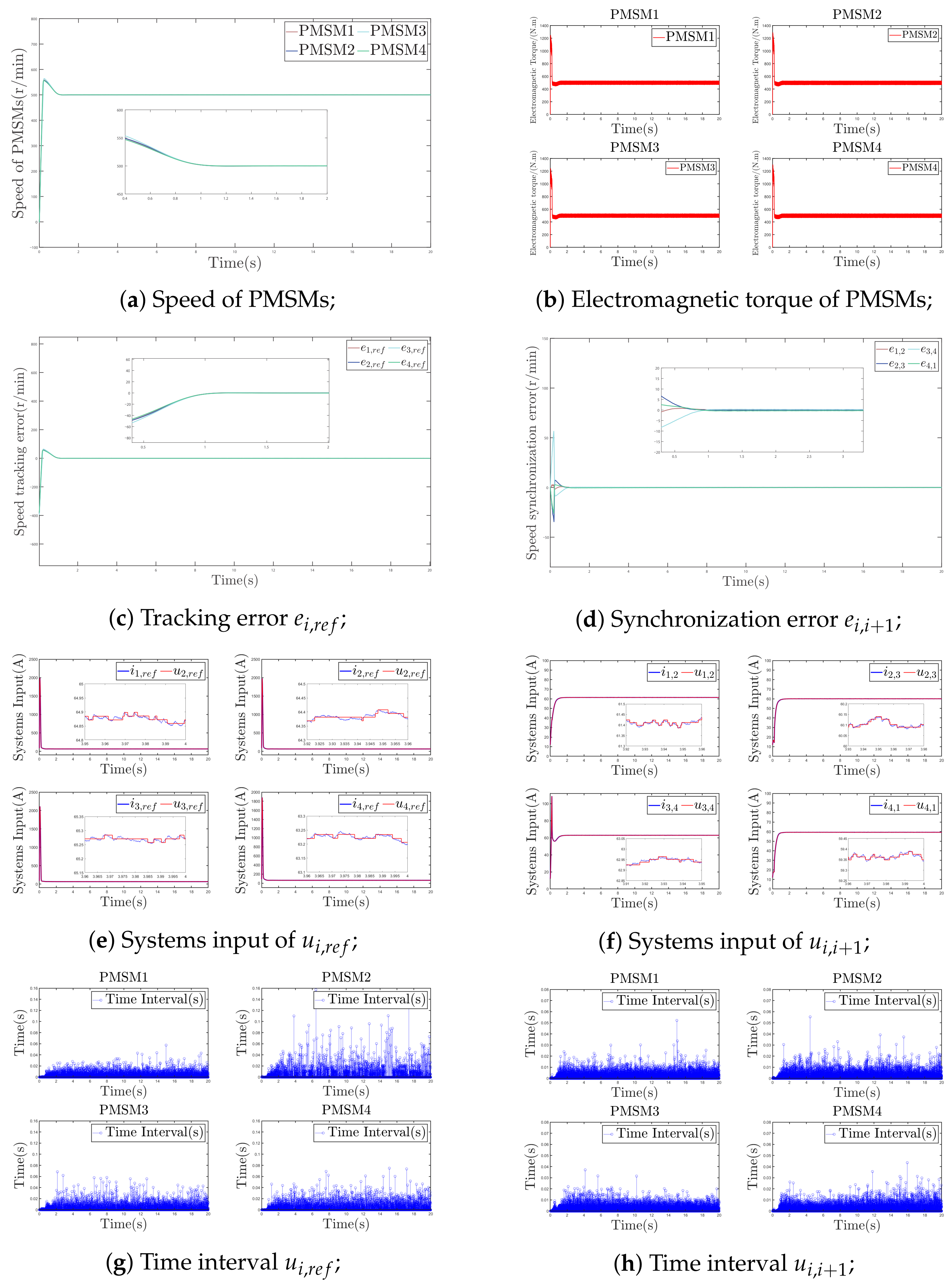
To verify the start-up performance of the multi-PMSMs during operation, the expected speed of four PMSMs is selected to be 500 r/min, initial torque is chosen as 500 N·m. Figure 2 shows the results of the simulation.
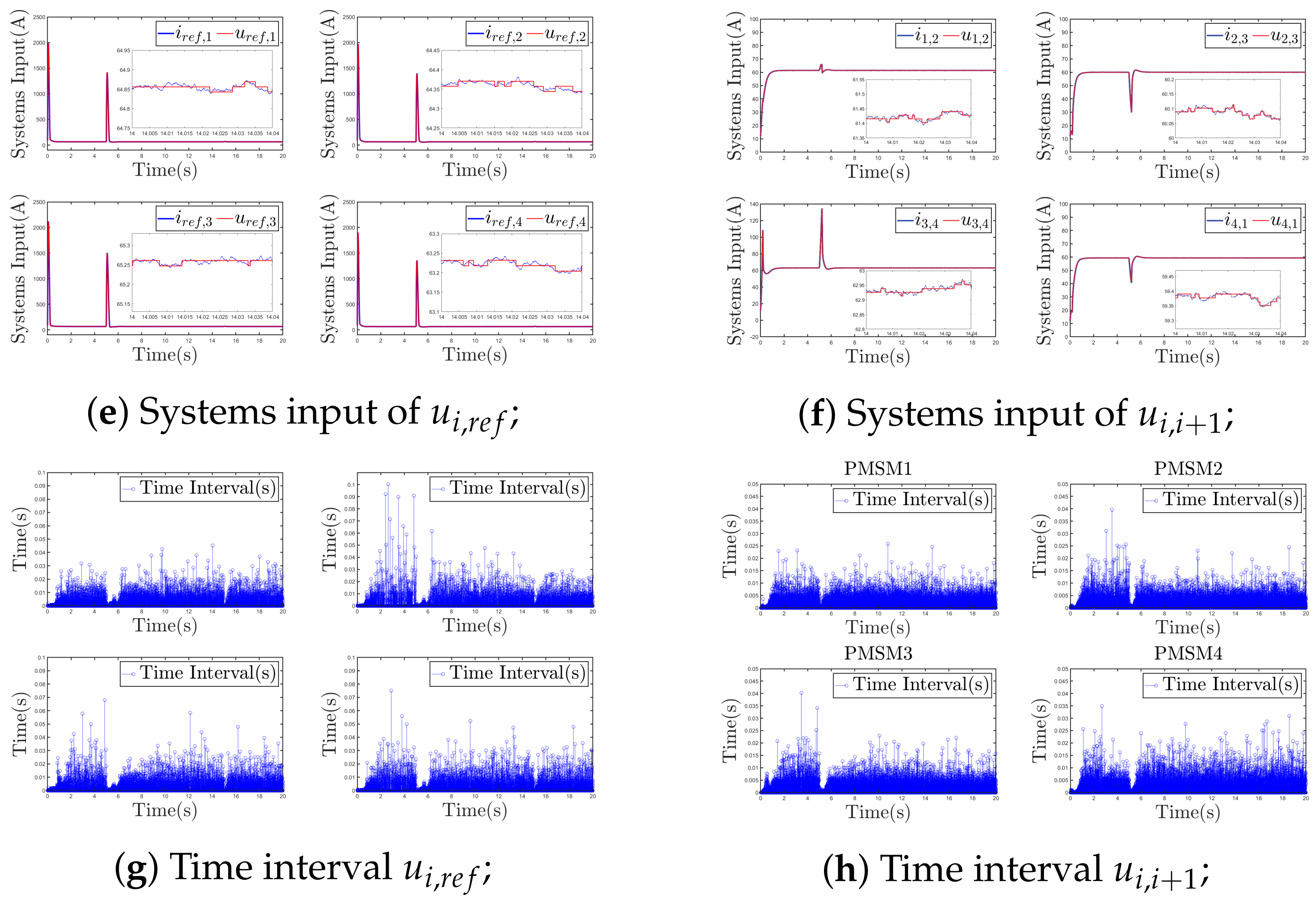
According to Figure 2, the proposed control method can stabilize the speed of the electric motor effectively. Figure 2a displays the speed of PMSMs, which shows an ideal start-up performance in which PMSMs can reach the expected speed within 1 s. Figure 2b shows the torque of PMSMs. The electromagnetic torque of the PMSMs rises rapidly and then drops sharply to 500 N·m. Figure 2c,d present the tracking error and synchronization error of each PMSM, respectively. All errors converge to ± 1 r/min in 1 s; it is obvious that PMSMs track the expected speed quickly and have excellent synchronization characteristics. Figure 2e,f depict the system input i i , r e f , i i , i + 1 and event-triggered input u i , r e f , u i , i + 1 , respectively. The triggering instants are presented in Figure 2g,h, which show that the maximum triggering intervals from PMSM1 to PMSM4 are 0.06 s, 0.16 s, 0.07 s and 0.08 s, respectively. Table 3 displays the triggered times of the ETM and the TTM, as the total triggered numbers are 126,390 and 1,600,000, respectively; 92.1% of communication resources can be saved by the proposed AETM.
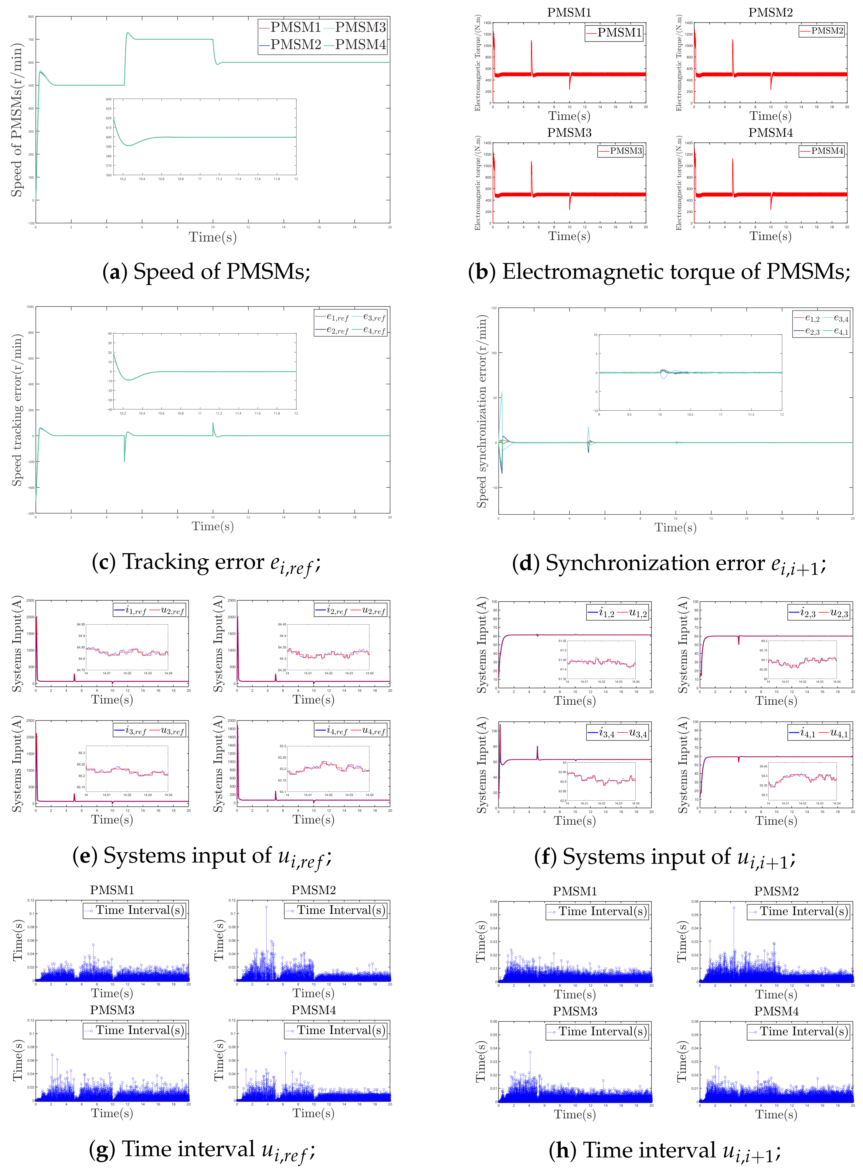
To evaluate the speed control performance of the multi-PMSMs, the expected speed of four PMSMs is initially set to 500 r/min at 0 s. Subsequently, the speed is increased to 700 r/min at 5 s, and then reduce to 600 r/min at 10 s. The initial load torque is selected as 500 N·m. Figure 3 presents the simulation results.
Figure 3 effectively shows excellent speed control capabilities of PMSMs with the proposed control strategy. Figure 3a exhibits the speed of PMSMs, which indicates the motor’s excellent regulation capability. The speed of PMSMs can be adjusted at 5 s and 10 s, respectively, and the PMSMs can quickly reach the desired speed within 0.6 s. Figure 3b provides the electromagnetic torque of PMSMs. When the desired speed of PMSMs changes, their electromagnetic torque also changes, thereby accelerating the tracking of the speed. When the actual speed attains the desired speed, the electromagnetic torque returns to a normal value. Figure 3c,d present the tracking error and synchronization error of each PMSM, respectively. The tracking error and synchronization error quickly converge to ± 1 r/min within 0.6 s after speed changes; it is clear that the PMSM can quickly reach the expected speed and has superior synchronization characteristics. Figure 3e,f depict the system input i i , r e f , i i , i + 1 and the event-triggered input u i , r e f , u i , i + 1 , respectively. The triggered time intervals are displayed in Figure 3g,h. This shows that the longest triggered time intervals from PMSM1 to PMSM4 are 0.05 s, 0.11 s, 0.07 s and 0.07 s, respectively. Table 4 displays the triggered times of the event-triggered and the time-triggered mechanism, as the total triggered numbers are 271,141 and 1,600,000, respectively. The proposed event-triggered mechanism can save 83.1 % of communication resources.
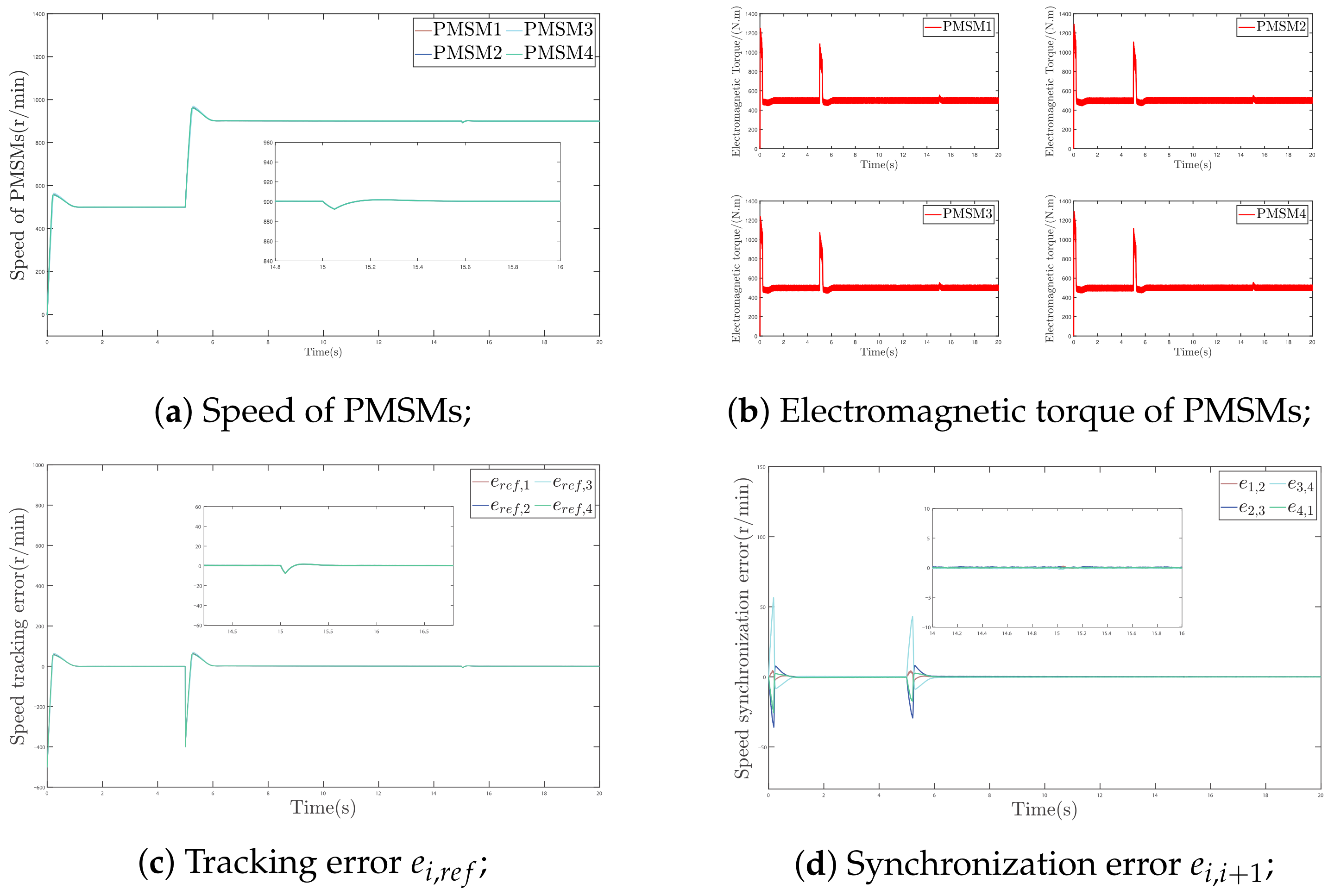
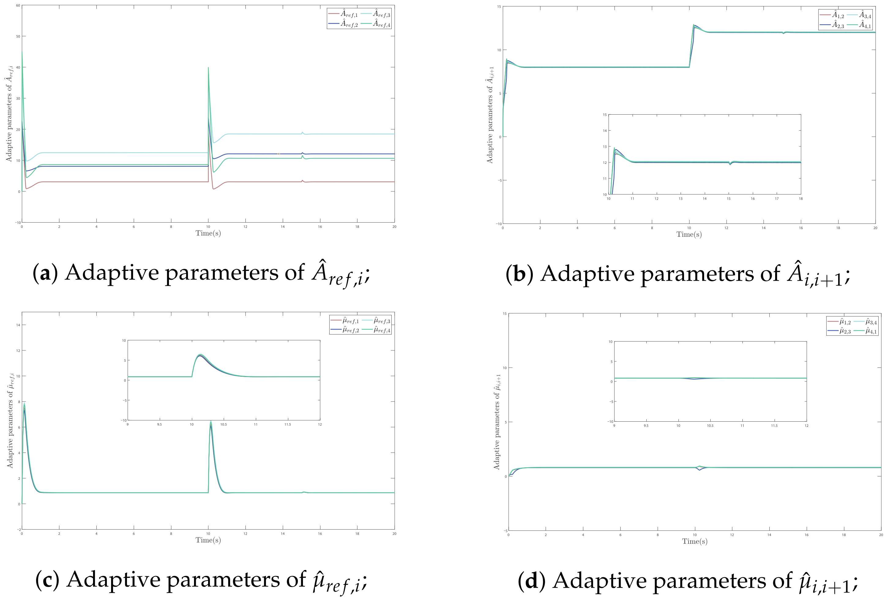
To verify the system’s disturbance rejection capability through anti-interference experiments. Set the expected speed to 500 r/min at 0 s, and increase the expected speed to 900 r/min at 5 s. At 15 s, add a 50 N·m load disturbance to test the system’s interference resistance. Figure 4 shows the results of the simulation and Figure 5 shows the adaptive parameters of Example 3.
According to Figure 4 and Figure 5, the proposed control method can stabilize the speed of the electric motor effectively. Figure 4a displays the speed of PMSMs. When the speed of PMSMs is regulated, it can quickly follow the desired speed. When a load disturbance is introduced at 15 s, the PMSMs can rapidly recover stability within 0.4 s while facing the load disturbance, displaying strong anti-interference capabilities. Figure 4b shows the electromagnetic torque of the PMSMs, and the electromagnetic torque of the PMSMs increases slightly after being disturbed and returns to normal when the motor speed stabilizes. Figure 4c,d present the tracking error and synchronization error of each PMSM, respectively. The tracking error converges to around ± 0.1 r/min after 0.4 s after being disturbed. The synchronization error converges rapidly within 0.2 s. Figure 4e,f present the system input i i , r e f , i i , i + 1 and event-triggered input u i , r e f , u i , i + 1 , respectively. Figure 4g,h show the triggered time intervals, which depict that the maximal triggered time intervals from PMSM1 to PMSM4 are 0.05 s, 0.1 s, 0.07 s and 0.07 s, respectively. Table 5 presents the triggered times of the event-triggered and the time-triggered mechanism, with the respective total trigger numbers being 126,390 and 1,600,000. The proposed event-triggered mechanism can save 92.1 % of communication resources. Figure 5 shows the adaptive parameters in Example 3. From Figure 5a–d, it can be seen that the adaptive parameters remain within a certain range and evolve reasonably, achieving good results.

4.2. Comparison with Related Works

The related work comparisons are shown in Table 6. Compared with the time-triggered ring-coupled ADRC scheme in [32] and the time-triggered master-slave PID scheme in [33], the proposed method adopts an adaptive event-triggered strategy that dynamically adjusts the triggering threshold according to the real-time control signal magnitude, thereby substantially reducing unnecessary signal transmissions while preserving comparable control accuracy. In contrast to [34], where a sliding mode control with an event-triggered mechanism is applied to a single PMSM, the proposed adaptive PI control avoids the chattering phenomenon inherent in SMC and extends the coordination capability to a four-PMSM ring-coupled system. Compared with [35], although both methods employ event-triggered strategies for four-PMSM systems, the proposed AET mechanism further incorporates adaptive threshold regulation based on the instantaneous control effort, achieving higher communication efficiency, while the integration of nonlinear adaptive PI with ring-coupled compensation provides stronger robustness against mismatched load disturbances and parameter uncertainties. Overall, the proposed method uniquely combines adaptive PI regulation, ring-coupled synchronization, and adaptive event-triggered communication within a unified framework, offering a favorable balance among tracking accuracy, synchronization performance, disturbance robustness, and communication efficiency. Three examples and are set up to prove that the proposed method can effectively start and speed control motors. Furthermore, this control strategy performs excellently in the face of load disturbance interference by comparing with related works.

5. Conclusions

A novel ring-coupled coordinated control strategy for multi-PMSMs is established based on nonlinear adaptive PI control with an event-triggered mechanism. To address unknown disturbances in multi-PMSMs, a nonlinear adaptive PI control was constructed. Additionally, an adaptive event-triggered mechanism was developed to reduce unnecessary communication, and Zeno behavior is successfully eliminated. The proposed adaptive PI control method based on event-triggering strategies effectively tracks the speed and ensures synchronous control in the presence of unknown interference. Eventually, the control method’s effectiveness is confirmed through simulations. In the future, the author will focus on the control of PMSMs when dealing with actuator failure issues.

Author Contributions

Conceptualization, J.L.; Investigation, J.Y.; Methodology, J.L.; Project administration, K.C.; Software, Z.W.; Supervision, K.C.; Validation, J.Y., Z.W. and K.C.; Resources, J.Y.; Writing—original draft, J.L.; Writing—review & editing, J.L., J.Y., Z.W. and K.C. All authors have read and agreed to the published version of the manuscript.

Funding

This work was supported in part by the Guangzhou Research and Development Program in Key Fields under Grant 202007020007.

Data Availability Statement

All relevant data are within the paper.

Conflicts of Interest

Author Jinbo Liu was employed by the company Guangdong Zhongnan Iron and Steel Co., Ltd. The remaining authors declare that the research was conducted in the absence of any commercial or financial relationships that could be construed as a potential conflict of interest.

References

  1. Dat, N.T.; Van Kien, C.; Anh, H.P.H. Advanced adaptive neural sliding mode control applied in PMSM driving system. Electr. Eng. 2023, 105, 3255–3262. [Google Scholar] [CrossRef]
  2. Wu, J.; Zhang, J.; Nie, B.; Liu, Y.; He, X. Adaptive Control of PMSM Servo System for Steering-by-Wire System with Disturbances Observation. IEEE Trans. Transp. Electrif. 2022, 8, 2015–2028. [Google Scholar] [CrossRef]
  3. Rafaq, M.S.; Midgley, W.; Steffen, T. A Review of the State of the Art of Torque Ripple Minimization Techniques for Permanent Magnet Synchronous Motors. IEEE Trans. Ind. Inf. 2024, 20, 1019–1031. [Google Scholar] [CrossRef]
  4. Dai, Y.; Zhang, L.; Xu, D.; Li, L.; Li, J.; Du, X. Fixed-time anti-disturbance constraint fuzzy synchronization control for PMSM based four-wheel-independent-drive EVs. J. Frankl. Inst. Eng. Appl. Math. 2024, 361, 106858. [Google Scholar] [CrossRef]
  5. Ma, C.; Huang, B.; Basher, M.K.; Rob, M.A.; Jiang, Y. Fuzzy PID Control Design of Mining Electric Locomotive Based on Permanent Magnet Synchronous Motor. Electronics 2024, 13, 1855. [Google Scholar] [CrossRef]
  6. Bu, W.; Guo, S.; Fan, Z.; Li, J. Improved Adaptive PI-like Fuzzy Control Strategy of Permanent Magnet Synchronous Motor. Energies 2025, 18, 362. [Google Scholar] [CrossRef]
  7. Veeresh, M.Y.; Reddy, V.N.B.; Kiranmayi, R. Modeling and Analysis of Time Response Parameters of a PMSM-Based Electric Vehicle with PI and PID Controllers. Eng. Technol. Appl. Sci. Res. 2022, 12, 9737–9741. [Google Scholar] [CrossRef]
  8. Wang, Q. An Intelligent System of Permanent Magnet Synchronous Using Synovial Motor Control and PID Motor Control for EoT Computing: A Comparative Simulation Study. Mob. Netw. Appl. 2023, 28, 2215–2223. [Google Scholar] [CrossRef]
  9. Liu, H.; Mei, K.; Liu, L.; Chang, Y.; Ding, S.; Zhang, H.; Wang, J. Fixed-time non-singular terminal sliding mode control for PMSM drive systems. J. Power Electron. 2024, 24, 258–268. [Google Scholar] [CrossRef]
  10. Khanh, P.Q.; Anh, H.P.H. Hybrid optimal fuzzy Jaya technique for advanced PMSM driving control. Electr. Eng. 2023, 105, 3629–3646. [Google Scholar] [CrossRef]
  11. Karimi, A.; Akbari, H.; Mousavi, S.; Beheshtipour, Z. Design of an adaptive terminal sliding mode to control the PMSM chaos phenomenon. Syst. Sci. Control Eng. 2023, 11, 2207593. [Google Scholar] [CrossRef]
  12. Zhang, J.; Ren, W.; Sun, X.M. Current-Constrained Adaptive Robust Control for Uncertain PMSM Drive Systems: Theory and Experimentation. IEEE Trans. Transp. Electrif. 2023, 9, 4158–4169. [Google Scholar] [CrossRef]
  13. Wu, X.; Wang, Y.; Wang, N.; Xing, H.; Xie, W.; Han, B.; Song, Y.; Lee, C.H.T. A Current Ripple Suppression Strategy for Model Predictive Current Control with an Improved Model of PMSM. IEEE J. Emerg. Sel. Top. Power Electron. 2025, 13, 1455–1466. [Google Scholar] [CrossRef]
  14. Li, T.; Sun, X.; Lei, G.; Guo, Y.; Yang, Z.; Zhu, J. Finite-Control-Set Model Predictive Control of Permanent Magnet Synchronous Motor Drive Systems—An Overview. IEEE/CAA J. Autom. Sin. 2022, 9, 2087–2105. [Google Scholar] [CrossRef]
  15. Liu, X.; Deng, Y.; Li, H.; Cao, H.; Sun, Z.; Yang, T. Composite control based on FNTSMC and adaptive neural network for PMSM system. ISA Trans. 2024, 151, 198–211. [Google Scholar] [CrossRef] [PubMed]
  16. Li, T.; Li, S.; Zhang, J.; Sun, H.; Zheng, C.; Lv, D. Adaptive-Neuro-Learning Tracking Control for the Permanent Magnet Synchronous Motor with Full-State Prescribed Performances and Time Delays. Int. J. Intell. Syst. 2023, 2023, 9926188. [Google Scholar] [CrossRef]
  17. Zhu, Y.; Zhao, H.; Cao, Z.; Sun, H.; Zhen, S. Fuzzy approach-based optimal robust control for permanent magnet synchronous motor with experimental validation. Asian J. Control 2023, 25, 170–189. [Google Scholar]
  18. Wang, C.; Liu, J.; Hong, Y.; Pan, J. Design of a Fuzzy-Based Adaptive Gain Filter for PMSM Servo Systems with Maneuverability. IEEE Trans. Ind. Inf. 2023, 19, 9394–9403. [Google Scholar] [CrossRef]
  19. Cordeiro, A.; Manuel, J.F.M.; Pires, V.F. Performance of synchronized master-slave closed-loop control of AC electric drives using real time motion over ethernet (RTMoE). Mechatronics 2020, 69, 102400. [Google Scholar] [CrossRef]
  20. Mu, Y.; Qi, L.; Sun, M.; Han, W. An Improved Deviation Coupling Control Method for Speed Synchronization of Multi-Motor Systems. Appl. Sci. 2024, 14, 5300. [Google Scholar] [CrossRef]
  21. Han, G.; Hong, J.; Chen, B.; Zhu, H.; Zhu, B.; Yu, D. An Improved Virtual-Shaft Control Strategy for Speed Synchronization of Dual-SRM Drive. IEEE Trans. Ind. Electron. 2024, 71, 5485–5495. [Google Scholar] [CrossRef]
  22. Zhang, X.; Hu, H.; Wang, H.; Wang, Z. Overview of position synchronous control technology for multi-motor system. Syst. Sci. Control Eng. 2024, 12, 2427074. [Google Scholar] [CrossRef]
  23. Liu, L.; Liu, C.; Che, C.; Wu, Y.; Zhao, Q. Research on the Coordinated Control of Mining Multi-PMSM Systems Based on an Improved Active Disturbance Rejection Controller. Electronics 2025, 14, 477. [Google Scholar] [CrossRef]
  24. He, R.; Xie, Y. Research on the Synchronization Control Strategy of Regenerative Braking of Distributed Drive Electric Vehicles. World Electr. Veh. J. 2024, 15, 512. [Google Scholar] [CrossRef]
  25. Liu, D.; Song, C.; Du, M.; Chen, G.; Liu, P.; AL-Shurufa, M.A.; Cheng, Y. Research on self-coupling PID for multi-driven synchronization control with ring adjacent compensation. Meas. Control 2024, 57, 291–300. [Google Scholar] [CrossRef]
  26. Pan, J.; Fu, P.; Niu, S.; Wang, C.; Zhang, X. High-Precision Coordinated Position Control of Integrated Permanent Magnet Synchronous Linear Motor Stations. IEEE Access 2020, 8, 126253–126265. [Google Scholar] [CrossRef]
  27. Wang, N.; Wang, Y.; Wen, G.; Lv, M.; Zhang, F. Fuzzy Adaptive Constrained Consensus Tracking of High-Order Multi-agent Networks: A New Event-Triggered Mechanism. IEEE Trans. Syst. Man. Cybern. Syst. 2022, 52, 5468–5480. [Google Scholar] [CrossRef]
  28. Song, J.; Wang, Y.K.; Niu, Y.; Lam, H.K.; He, S.; Liu, H. Periodic Event-Triggered Terminal Sliding Mode Speed Control for Networked PMSM System: A GA-Optimized Extended State Observer Approach. IEEE/ASME Trans. Mechatron. 2022, 27, 4153–4164. [Google Scholar] [CrossRef]
  29. Tan, L.N.; Cong, T.P.; Cong, D.P. Event-Triggered Robust Optimal Control for PMSM with Unknown Internal Dynamics, Disturbances, and Constrained Inputs. IEEE Access 2024, 12, 9112–9122. [Google Scholar] [CrossRef]
  30. Xing, L.; Wen, C.; Liu, Z.; Su, H.; Cai, J. Event-Triggered Adaptive Control for a Class of Uncertain Nonlinear Systems. IEEE Trans. Autom. Control 2017, 62, 2071–2076. [Google Scholar] [CrossRef]
  31. Wang, X.; Wang, B.; Chen, X.; Yu, J. Event-Triggered Tracking and Synchronization Control for Multimotor Driving Systems via Command Filtering Technique. IEEE Trans. Ind. Inform. 2025, 21, 5834–5844. [Google Scholar] [CrossRef]
  32. Li, L.B.; Sun, L.L.; Zhang, S.Z.; Yang, Q.Q. Speed tracking and synchronization of multiple motors using ring coupling control and adaptive sliding mode control. ISA Trans. 2015, 58, 635–649. [Google Scholar] [CrossRef] [PubMed]
  33. Yeh, S.S.; Hong, M.J. Proportional-integral-proportional control and compensation design for low-speed motions of permanent magnet synchronous motor driven servomechanism with position-dependent disturbance. J. Chin. Inst. Eng. 2022, 45, 602–612. [Google Scholar] [CrossRef]
  34. Gu, J.; You, S.; Kim, W.; Moon, J. Fuzzy Event-Triggered Super Twisting Sliding Mode Control for Position Tracking of Permanent Magnet Synchronous Motors Under Unknown Disturbances. IEEE Trans. Ind. Inform. 2023, 19, 9843–9854. [Google Scholar] [CrossRef]
  35. Li, Z.; Sun, F.; Wang, B.; Cai, M. Four-Motor Servo System Command-Filtered Synchronous Control Based on Feedback Channel Event-Triggered Mechanism. Energies 2026, 19, 2567. [Google Scholar] [CrossRef]
Figure 1. Design of the Ring-coupled control structure of multi-PMSMs.
Machines 14 00869 g001
Figure 2. The simulation results of Example 1.
Machines 14 00869 g002
Figure 3. The simulation results of Example 2.
Machines 14 00869 g003
Figure 4. The simulation results of Example 3.
Machines 14 00869 g004aMachines 14 00869 g004b
Figure 5. The Adaptive parameters of Example 3.
Machines 14 00869 g005
Table 1. Multi-PMSMs parameters [32].
VariablePMSM1PMSM2PMSM3PMSM4
R s [ Ω ] 2.890 2.875 2.880 2.880
L d [H] 0.0015 0.0015 0.0015 0.0015
L q [H] 0.0015 0.0015 0.0015 0.0015
n p 4444
B m [ N · m · s ] 0.001 0.002 0.0015 0.001
J [ kg · m 2 ] 2.00 2.00 2.05 2.10
ψ f [ Wb ] 0.66 0.67 0.64 0.66
P n [kW]150150150150
I n [kW]300300300300
Table 2. The controller parameters of Examples.
The parameters of controllers Φ ¯ i = 0.005 , χ i , 1 = 0.048 , K P , 1 = 2.51 , χ i , 2 = 0.06 , K P , 2 = 2.62 , q 1 = e 0.002 t , q 2 = e 0.001 t , ψ 0 = ψ 2 = 0.08 , ψ 1 = 0.2 , ψ 3 = 0.15 , ρ i = 0.002 , k i = 3.5
The parameter of event-triggered mechanism ξ i , r e f = 0.0002 , ϑ i = 0.001 , o i = 0.3 , ξ i , i + 1 = 0.001
Table 3. The times of the event-triggered and the time-triggered mechanism in Example 1.
MechanismPMSM1PMSM2PMSM3PMSM4Total
Event-triggered Mechanism31,41831,70234,04529,225126,390
Time-triggered Mechanism400,000400,000400,000400,0001,600,000
Rate 92.1 % 92.1 % 91.5 % 92.7 % 92.1 %
Table 4. The times of the event-triggered and the time-triggered mechanism in Example 2.
MechanismPMSM1PMSM2PMSM3PMSM4Total
Event-triggered Mechanism67,22171,72469,35762,839271,141
Time-triggered Mechanism400,000400,000400,000400,0001,600,000
Rate 83.2 % 82.1 % 82.7 % 84.2 % 83.1 %
Table 5. The times of the event-triggered and the time-triggered mechanism in Example 3.
MechanismPMSM1PMSM2PMSM3PMSM4Total
Event-triggered Mechanism52,21857,81058,75250,995219,775
Time-triggered Mechanism400,000400,000400,000400,0001,600,000
Rate 86.9 % 85.5 % 85.3 % 87.3 % 86.3 %
Table 6. Comparison with related works.
SchemeControl MethodTriggered StrategyNumber of PMSMs
In [23]ADRC + RCCTT3
In [33]PID + MSCTT2
In [34]SMCET1
In [35]FTC + CFCET4
ProposedAdaptive PI + RCCAET4
ET = Event-Triggered, TT = Time-Triggered, AET = Adaptive Event-Triggered, RCC = Ring-Coupled control, ADRC = Active Disturbance Rejection Control, MSC = Master-Slave Control, FTC = fixed-time control, CFC = Command-Filtered Control.
Disclaimer/Publisher’s Note: The statements, opinions and data contained in all publications are solely those of the individual author(s) and contributor(s) and not of MDPI and/or the editor(s). MDPI and/or the editor(s) disclaim responsibility for any injury to people or property resulting from any ideas, methods, instructions or products referred to in the content.