Article

Integrated FEM Evaluation and Optimization of Excavation, Loading, and ROPS/FOPS Systems in a Skid-Steer Loader

by
Diego Andrés Duque-Sarmiento
*,
Gustavo Morocho
,
Juan José Molina-Campoverde
and
Xavier Narváez
Grupo de Ingeniería Automotriz, Movilidad y Transporte (GiAUTO), Carrera de Ingeniería Automotriz-Campus Sur, Universidad Politécnica Salesiana, Quito 170702, Ecuador
*
Author to whom correspondence should be addressed.
Machines 2026, 14(7), 833; https://doi.org/10.3390/machines14070833
Submission received: 5 June 2026 / Revised: 10 July 2026 / Accepted: 15 July 2026 / Published: 22 July 2026
(This article belongs to the Section Machine Design and Theory)

Abstract

This study proposes an integrated finite element methodology for evaluating and redesigning three critical subsystems of an XCMG XC740K skid-steer loader: the excavation attachment, the arm–bucket charging system, and the ROPS/FOPS operator protection cab. The components were reconstructed by reverse engineering and 3D scanning, modeled in CAD, and simulated in ANSYS Workbench/Mechanical under load cases derived from hydraulic parameters, soil–tool interaction, and international safety standards. The novelty of the work lies in applying a single FEM-based workflow to three interacting subsystems of the same compact machine, rather than optimizing isolated components independently. The original configuration showed critical effort concentrations in the cab and charging system. Localized geometric reinforcements and the use of high-strength and wear-resistant steels improved stiffness and safety margins in the excavation bucket, loading bucket, and ROPS/FOPS cab. However, the arm–quick coupler region remained the controlling weak point of the loading assembly, indicating the need for further redesign. The proposed approach provides a transferable computational framework for identifying structural vulnerabilities and prioritizing redesign actions in compact earthmoving machinery. Because the study is numerical, future experimental validation is required before certification or field implementation.

1. Introduction

Heavy machinery, particularly skid-steer loaders, plays a strategic role in sectors such as construction, mining, and agriculture, where their compact geometry, maneuverability, and functional versatility enable operations to be carried out in confined spaces and under severe service conditions [1,2,3]. In this context, productivity cannot be separated from structural reliability or operator safety, since repeated loads, impacts, soil–tool interaction, and aggressive working environments accelerate mechanical deterioration and increase the risk of failure [2,4,5].
One of the most recurrent problems in earthmoving machinery is effort concentration in welded joints, abrupt geometric transitions, connection plates, and pin housings, which are areas where cracks, localized deformations, and fatigue processes commonly initiate [4,5]. In compact platforms, this problem becomes more relevant because a single machine may integrate excavation tools, charging systems, and operator protection structures, subjecting the assembly to variable load paths and severe loading conditions. Therefore, the optimization of critical subsystems not only responds to durability criteria but also to requirements related to safety, operational availability, and regulatory compliance [3,5].
Within this framework, finite element analysis (FEA/FEM) has become established as a robust tool for the design, verification, and redesign of machinery, as it enables the prediction of effort fields, deformation patterns, and safety factors under representative working conditions, thereby reducing dependence on costly physical testing [6]. The literature on excavation systems confirms its usefulness. Scientific researchers [7] reported that the relationship between maximum deformation and the thickness of structural plates is a determining factor in the performance of heavy-duty buckets. Similarly, other researchers [8] observed that the inclination angle has a limited influence on deformation, but identified welds and geometric discontinuities as critical effort concentration points. Complementarily, Coloma Morales [9] reported structural improvements in optimized buckets, whereas Chunlei Yu et al. [10] demonstrated that local thickness increase, the incorporation of side plates, and the adjustment of curvature radii significantly reduce efforts in excavator booms.
These precedents also reveal an important divergence within the field. While some studies emphasize the influence of global geometric or kinematic parameters on structural response, others show that effective effort mitigation depends primarily on local reinforcement strategies, thickness redistribution, and the control of geometric discontinuities [8,10]. In addition, material selection is incorporated as a design variable. In this regard, Odey Alshboul et al. [11] proposed that earthmoving machinery should be addressed through multi-objective optimization schemes that integrate structural response, durability, and operational performance, rather than being limited to isolated material replacement. This perspective is especially relevant in compact equipment, where weight, manufacturability, wear resistance, and safety must be balanced simultaneously.
In parallel, operator protection must be understood as a structural problem in itself. ROPS and FOPS are governed by strict international standards, particularly ISO 3471 and ISO 3449, which establish performance requirements and test methods for earthmoving machinery [12,13]. Consequently, cab safety cannot be treated as an ancillary design element, but rather as a critical subsystem whose response must be evaluated under standardized loads and representative impact scenarios.
Despite these advances, most available research has focused on conventional excavators or on isolated components, such as booms, buckets, or welded joints. In contrast, excavation attachments integrated into skid-steer loaders feature non-conventional configurations and different load paths, which requires adapting both the calculation models and the optimization criteria. Furthermore, the estimation of tool forces continues to rely on regulatory and theoretical frameworks such as ISO 6015, SAE J296, and soil mechanics approaches derived from Terzaghi [14,15], whose application in compact systems requires adaptations when geometry, kinematics, or manufacturer documentation is limited. This gap becomes even more evident when there is no validated methodology with quantified uncertainty to simultaneously evaluate the excavation, loading, and ROPS/FOPS protection subsystems of compact skid-steer loaders reconstructed through reverse engineering.
In this context, the present study evaluates and optimizes three critical subsystems of an XCMG XC740K skid-steer loader: the excavation system, the arm–bucket charging system, and the ROPS/FOPS cab safety structure. To this end, reverse engineering, CAD modeling, finite element simulation, material selection, and geometric redesign are integrated under boundary conditions defined based on hydraulic parameters, soil–tool interaction criteria, and international standards applicable to earthmoving machinery. The main objective is to identify critical effort concentration zones, reduce deformations, increase safety factors, and improve the structural integrity of the equipment without compromising its functional performance.
Although FEM-based redesign of buckets, booms, welded joints, and protective structures has been widely reported, most available studies treat these components independently. This separation limits the ability to compare load paths, safety margins, and residual vulnerabilities within the same compact machine. The present work addresses this limitation by applying a unified workflow to excavation, loading, and ROPS/FOPS subsystems reconstructed from the same skid-steer loader. The novelty is therefore not the use of FEM alone, but the integrated evaluation of multiple critical subsystems using consistent geometry acquisition, load definition, material selection, mesh convergence, and uncertainty criteria. This approach allows the redesign to be prioritized according to the hierarchy of structural vulnerabilities observed in a single machine platform.
Accordingly, the main contributions of this work are as follows: (1) an integrated FEM-based workflow is proposed for evaluating excavation, loading, and ROPS/FOPS subsystems within the same reverse-engineered skid-steer loader platform; (2) hydraulic-force estimation, soil–tool interaction, distributed loading, and ROPS/FOPS regulatory load cases are combined into a unified load-definition procedure; and (3) the redesign is interpreted at subsystem and component levels, distinguishing components that become structurally acceptable from those that remain critical and require further optimization.

2. Materials and Methods

2.1. Study Platform and General Methodological Approach

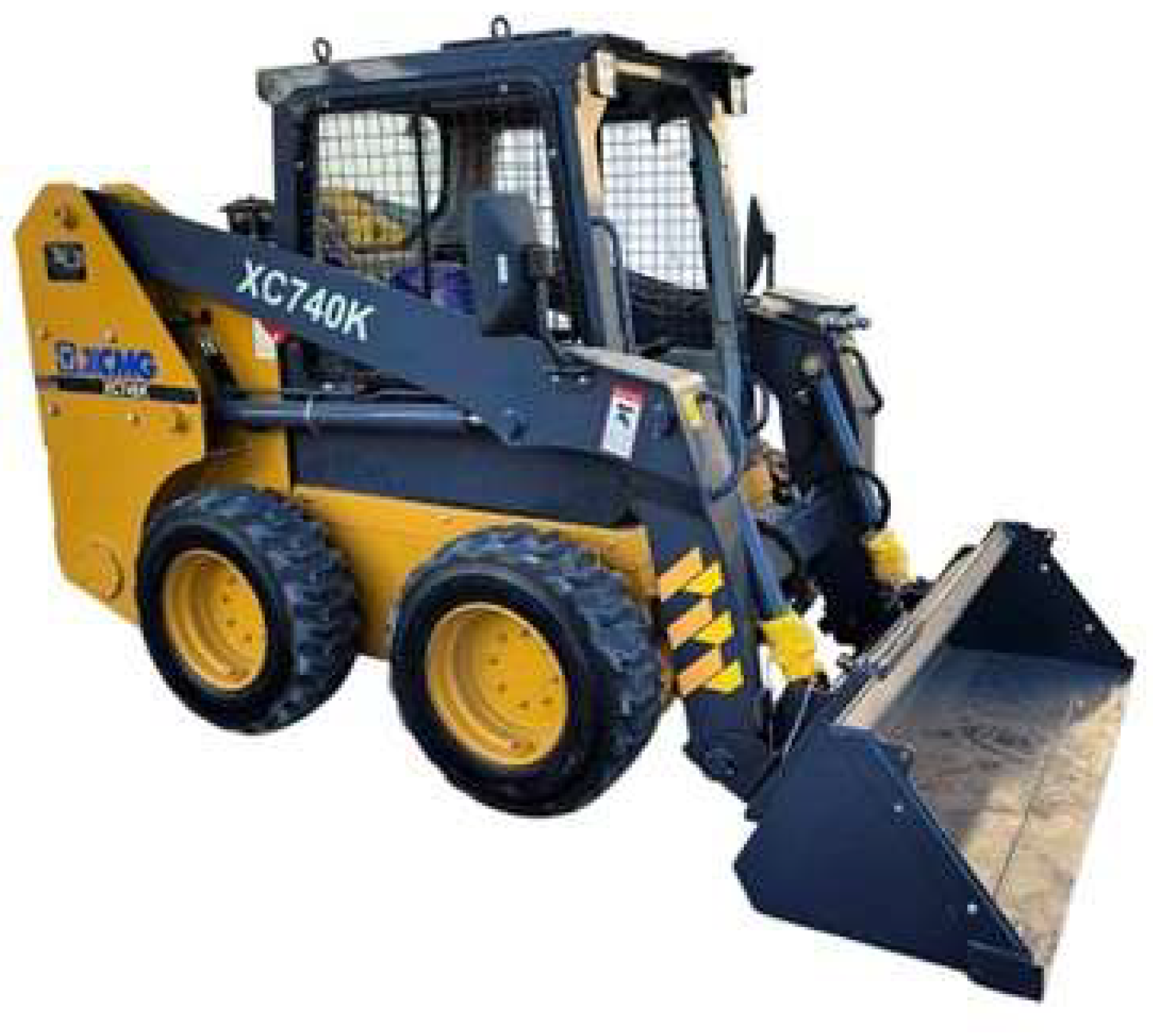
The study unit used in this research was an XCMG XC740K skid-steer loader(XCMG Construction Machinery Co., Ltd., Xuzhou, Jiangsu, China), shown in Figure 1, which was used as a common platform for the integrated analysis of three structurally critical subsystems: (1) the single-arm excavation system, (2) the arm–bucket charging system, and (3) the ROPS/FOPS cab safety structure. This machine is classified as a compact loader according to ISO 6165 [16], and was selected for its operational versatility, its availability as a teaching and research platform, and its representativeness within the context of compact machinery used in Latin America [17,18].
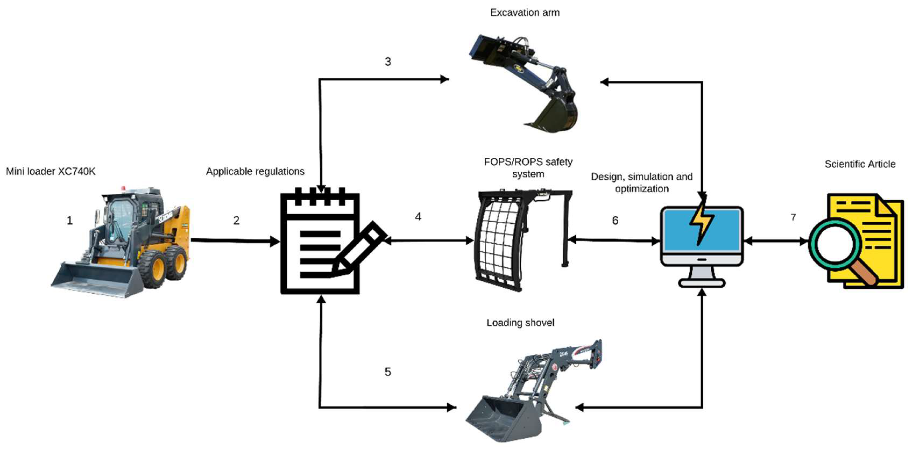
The research followed an integrated theoretical–computational approach structured into four phases: (1) regulatory review and definition of the calculation framework, (2) geometric acquisition through metrology and reverse engineering, (3) CAD modeling and simulation using the finite element method (FEM), and (4) geometric optimization and comparative validation between the initial and redesigned configurations, as shown in Figure 2.
The experimental platform of the present study is shown in Table 1. The methodological structure made it possible to evaluate the three subsystems homogeneously, using total deformation, von Mises equivalent efforts, and safety factor as common response variables [5,19].

2.2. Capture and Reverse Engineering

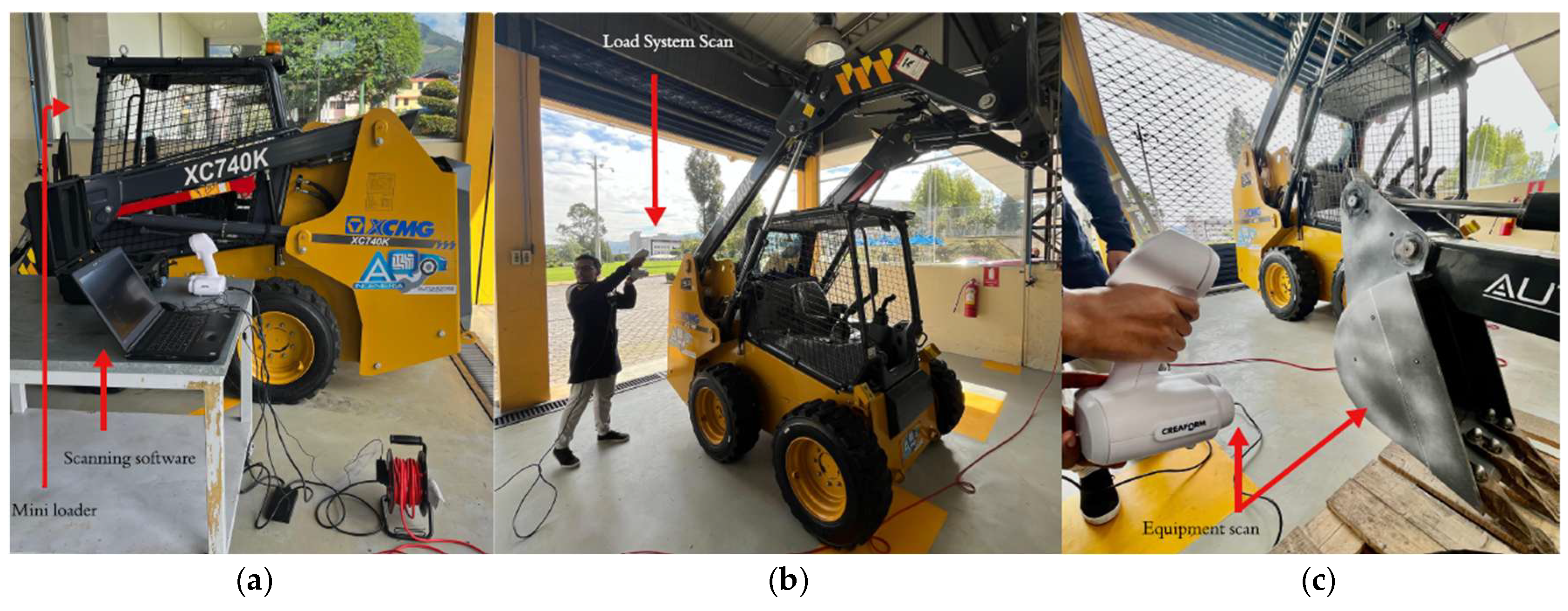
Due to the absence of original manufacturer drawings, the geometric reconstruction of the components was carried out through a reverse engineering process, as shown in Figure 3. In the first stage, direct measurements were performed using calibrated conventional instruments, and, in the case of the excavation system, three measurements were taken for each dimension to improve the accuracy and repeatability of the survey. Subsequently, three-dimensional scanning techniques were used with a Creaform Go!SCAN 50 (Creaform Inc., Lévis, Québec, Canada)., selected for its ability to capture regions with curvature radii, joint angles, and complex geometric transitions [20], with a scanner accuracy of ±0.050 mm. The information obtained was processed using VXelements 10.2.3, generating sketches and geometric reconstructions prior to parametric modeling.
Computer-aided modeling was carried out in Autodesk Inventor Professional using a component-based modeling strategy followed by assembly. In the charging system, the main arm, secondary arm, mechanical quick-coupler system, and bucket were modeled; in the excavation system, the hydraulic subassembly and pins were also integrated; and in the cab, profiles, thicknesses, joints, and structural reinforcements were defined.
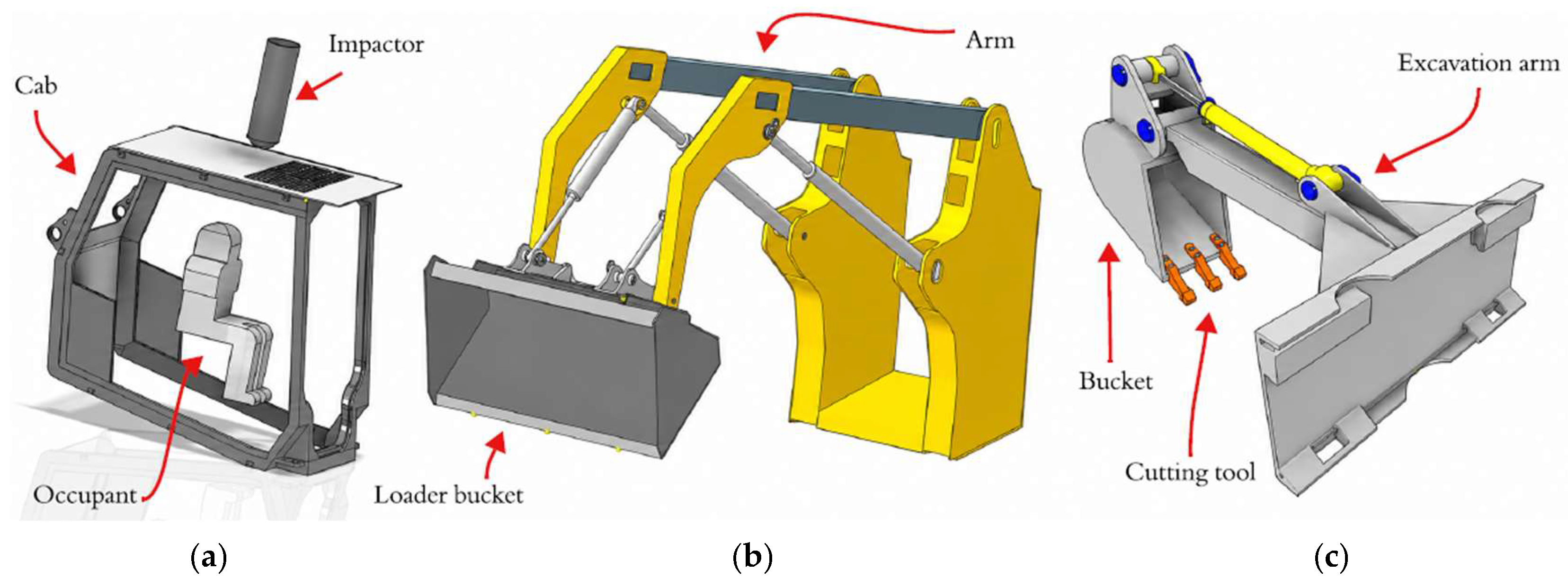
Figure 4 shows the CAD modeling of the critical subsystems: (a) the cab, (b) the arm–bucket system, and (c) the excavation system [19]. The equipment and software used for this process are detailed in Table 2:

2.3. Materials Used in the Simulations

Structural materials were selected according to their use in heavy machinery and the specifications reported by the manufacturer or their simulation equivalents. In the excavation system, the initial configuration included steel such as AISI 1045, whereas in the bucket optimization stage, Dillidur 450 was implemented due to its high wear resistance and good performance under high loading conditions [21]. In the cab safety structure, the original material was ASTM A572 Grade 50, which was subsequently replaced with ASTM A514 to improve the structural strength of the ROPS/FOPS system. In the charging system, AISI 1045 was initially included, and ASTM A514 Grade Q was subsequently used [22].
The physical–mechanical properties considered in the numerical models included density, modulus of elasticity, poison coefficient, yield strength, and ultimate tensile strength [22]. For traceability and reproducibility appeals, Table 3 summarizes the values identified directly in the development documents.

2.4. Definition of Loads and Boundary Conditions

2.4.1. Excavation System

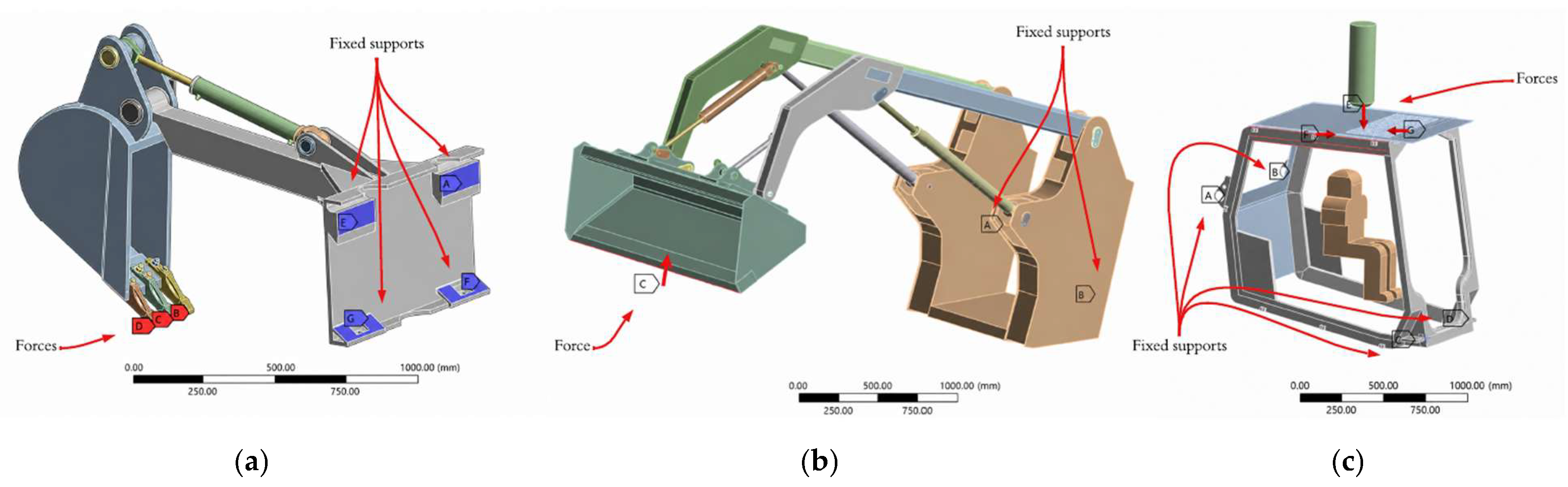
The excavation system was modeled as a non-conventional single-arm attachment. Load determination was based on ISO 6015 for calculating tool forces, SAE J296 for bucket volumetric capacity, and Terzaghi’s bearing capacity theory to represent soil–tool interaction [14,15,23,24]. In addition, the bending moment of the arm and the shear efforts in the pins were based on classical strength-of-materials formulations [23]. The penetration force, grip force, breakout force, tearing force, arm bending moment, and pin shear efforts were calculated using a bucket volumetric capacity of 0.06 m3 [14,23]. Since the system studied does not exactly reproduce the kinematics of a conventional excavator, the calculation procedure was adapted to the actual geometry of the attachment. The structural behavior of the assembly was evaluated through static structural analysis in ANSYS Mechanical using AISI 1045 material, as shown in Figure 5a.
Calculation of Hydraulic Loads and Tool Forces
To define the loads applied in the FEM model of the excavation system, the effective areas of the double-acting hydraulic cylinder were first calculated. In extension or traction mode, the effective piston area was obtained using the following equation:
A e x t e n s i o n = π · D 2 / 4
On the other hand, in retraction mode, the effective area was calculated by subtracting the area occupied by the piston rod:
A r e t r a c t i o n = π · ( D 2 d 2 ) / 4
where D is the inner diameter of the cylinder and d is the diameter of the piston rod. The hydraulic force available during extension was calculated as
F e x t e n s i o n = P · A e x t · η h
and the hydraulic force available during retraction was calculated as
F r e t r a c t i o n = P · A r e t · η h
where P is the hydraulic pressure of the system and η h is hydraulic efficiency. When hydraulic losses were not taken into account, η h = 1 was adopted.
The startup force was estimated based on the hydraulic force during extension,
F s t a r t u p = P · A e x t
while the tear strength was calculated using the effective area during retraction,
F t e a r = P · A r e t
To model soil–tool interaction during the bucket’s penetration phase, a simplified relationship was used between soil shear resistance, contact area, and a bucket efficiency factor:
F p e n e t r a t i o n = k · σ s · A c
where F p e n e t r a t i o n is the penetration force, k is the bucket efficiency factor, σ s is the soil’s shear strength and A c is the contact area between the tool and the ground. In this study, k = 0.7 and σ s = 0.3   MPa were considered, corresponding to a condition representative of wet clay.
Calculation of Bending Moment and Shear Force in Dowels
The mass of the material contained in the bucket was calculated from the volumetric capacity and soil density:
m s = ρ s · V c
where m s is the mass of the excavated material, ρ s is the soil density and V c is the volumetric capacity of the scoop. The vertical force associated with this mass was obtained by
F v = m s · g
where g = 9.81 m / s 2 . The maximum bending moment in the arm was estimated by considering the greatest lever arm between the arm’s fulcrum and the coupling pin on the bucket:
M b = F v · L b
where L b = 1.10424   m   corresponds to the critical lever length identified in the geometric model.
The average shear effort at each pin was calculated using
τ p = F v n · A P
where n represents the number of cutting planes, with n = 1 for single-edge and n = 2 for a double-edged cutter. The cross-sectional area of the pin was calculated as
A p = π · d p 2 4
where d p is the diameter of the pin. This formula was applied separately to the three pins in the excavation system.
Input parameters and final loads applied in the FEM models are shown in Table 4:

2.4.2. Charging System

The charging system, consisting of the main arm, secondary arm, quick coupler, and bucket, was evaluated exclusively through static structural analysis. The applied load was defined based on the hydraulic parameters of the equipment and the estimated resistance of the material to be excavated, representing a demanding working scenario on the bucket cutting edge. A distributed load of 28,856.1 N was obtained and applied to the bucket edge at an angle of 45° with respect to the cutting blade, as shown in Figure 5b, together with fixed supports in the attachment zones of the model. The following parameters were also used to define the load: rod diameter of 35 mm, internal cylinder diameter of 50 mm, hydraulic pressure of 21 MPa, bucket efficiency factor k = 0.7, and soil resistance σ = 0.3 MPa for wet clay [24]. On this basis, the structural performance of the bucket and boom was compared with that of AISI 1045 steel [22].
To apply the resultant force to the bucket cutting edge, the load was decomposed into its horizontal and vertical components considering an application angle of 45 :
F X = F l o a d i n g · C o s θ
F y = F l o a d i n g · S i n θ
where F l o a d i n g = 28,856.1   N   y θ = 45 . Therefore,
F X = F y = 20,404.3   N
If the force was applied as a linearly distributed load along the blade tip, the equivalent intensity was obtained by
q = F l o a d i n g L f
where q is the distributed linear load and L f is the effective length of the blade’s cutting edge. If the load was applied as pressure on a contact surface, the equivalent pressure was calculated as follows:
F l a t e r a l = 6 · M
F l a t e r a l = 1.5 · M
F v e r t i c a l = 2 · M · g
F l o n g i t u d i n a l = 4.81 · M

2.4.3. Cab Safety System (ROPS/FOPS)

The cab evaluation was performed by distinguishing between the ROPS and FOPS scenarios. For ROPS, SAE J1040 and ISO 3471 were adopted, using a working dough of 3140 kg to determine the equivalent loads [25]. A lateral force of 18,840 N, a vertical load of 61,575.4 N, a longitudinal force of 15,103.4 N, and a lateral energy of 4710 J were calculated. This analysis was performed using the Static Structural module of ANSYS Workbench, with ASTM A572 Grade 50 material, as shown in Figure 5c.
M = 3140   kg is the working dough used for ROPS/FOPS and g = 9.81 m / s 2 . These relationships yielded F l a t = 18,840   N , E l a t = 4710   J , F v e r t = 61,575.4   N and F l o n g = 15,103.4   N .
For the FOPS assessment, the impact energy was calculated based on the potential energy of the object in free fall:
E F O P S =   m i   ·   g   ·   h
where m i = 227   kg is the mass of the impactor and h = 10   m is the drop height. The initial velocity of the impactor was calculated using
V 0 = 2   ·   g   ·   h
For FOPS, ISO 3449:2005 and ISO 3164:2013 were used, considering a 227 kg object in free fall from 10 m, equivalent to an impact energy of 22,270 J [13,26] using ASTM A572 Grade 50 material. The corresponding simulation was developed in Explicit Dynamics, with an initial velocity of 14 m/s and a total analysis time of 3 s. This methodological separation was necessary to adequately represent both the quasi-static loads, listed in Table 5, which are associated with rollover, and the transient nature of the impact on the cab [13,26].

2.5. Finite Element Method Configuration, Meshing Strategy, and Convergence

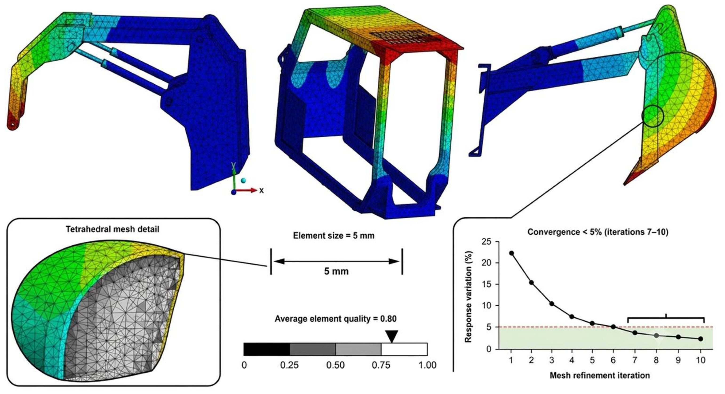
All simulations were performed in ANSYS Workbench/Mechanical 2024 R1, using total deformation, von Mises equivalent efforts, and safety factor as response variables. In the excavation system, an element size of 5 mm, an average mesh quality of 0.84 according to the Element Quality metric, and convergence below 5% after seven refinement iterations were reported. In the charging system, a convergence study with successive refinements of 14, 12, 10, 8, and 6 mm was described, with quality values between 0.824 and 0.834; a mesh with an element size of 6 mm was finally adopted for the comparative analysis of the bucket. In the ROPS/FOPS cab, mesh convergence below 5% was also achieved, with high mesh quality ranging from 0.859 to 0.961, as shown in Figure 6.

Numerical Model Details for Reproducibility

All structural components were discretized using three-dimensional solid elements. The static structural models were meshed with quadratic tetrahedral elements for 10-node quadratic tetrahedra, while the FOPS impact model used explicit solid elements compatible with ANSYS Explicit Dynamics. The final number of elements and nodes for each subsystem is reported in Table 6. Welded or continuously joined plate interfaces were represented as bonded contacts, and the corresponding weld regions were locally refined instead of explicitly modeling weld beads. Pin connections were represented by cylindrical contact/remote-joint definitions at the pin axes, allowing rotation while transferring shear and normal loads; where pins were explicitly included, the pin–bushing interfaces were modeled as frictionless. Fixed supports were applied only on the mounting pads or bracket surfaces that represent bolted attachments to the machine frame. Loads were applied as distributed forces or pressures over the actual CAD surfaces in contact with soil, the bucket edge, or the ROPS/FOPS loading device. Static analyses were solved using the module Static Structural, with a convergence rate of less than 5%, automatic time stepping ON, and large-deflection effects ON. The excavation and loading models were treated as linear-elastic screening analyses. For ROPS/FOPS cases, efforts above the material yield strength were interpreted as indicators of non-compliance unless an elastoplastic material model was explicitly activated. In Explicit Dynamics, the impactor–cab contact was modeled using general contact, the initial impact velocity was 14 m/s, the total simulation time was 5 s, and the stable time step was automatically controlled by the smallest element size; any mass scaling, if used, is reported in Table 6.
Contact, joint, and material-model assumptions were defined according to the physical appeal of each interface. Welded plate interfaces were modeled as bonded contacts, while pin-connected regions were represented using cylindrical contact/remote-joint definitions to allow rotation and load transfer. Loads were applied over the CAD surfaces that physically interacted with the bucket edge, soil, ROPS loading plate, or FOPS impactor, rather than at isolated nodes. The excavation and loading subsystems were modeled as linear-elastic because the objective was comparative stiffness and effort screening under static loading. For the baseline ROPS/FOPS, effort values exceeding yield were interpreted as failure indicators and not as real post-yield effort predictions. In the optimized ROPS/FOPS assessment, a linear-elastic material behavior model was used. If plasticity was not activated, the manuscript must state explicitly that certification-level conclusions require nonlinear material validation.
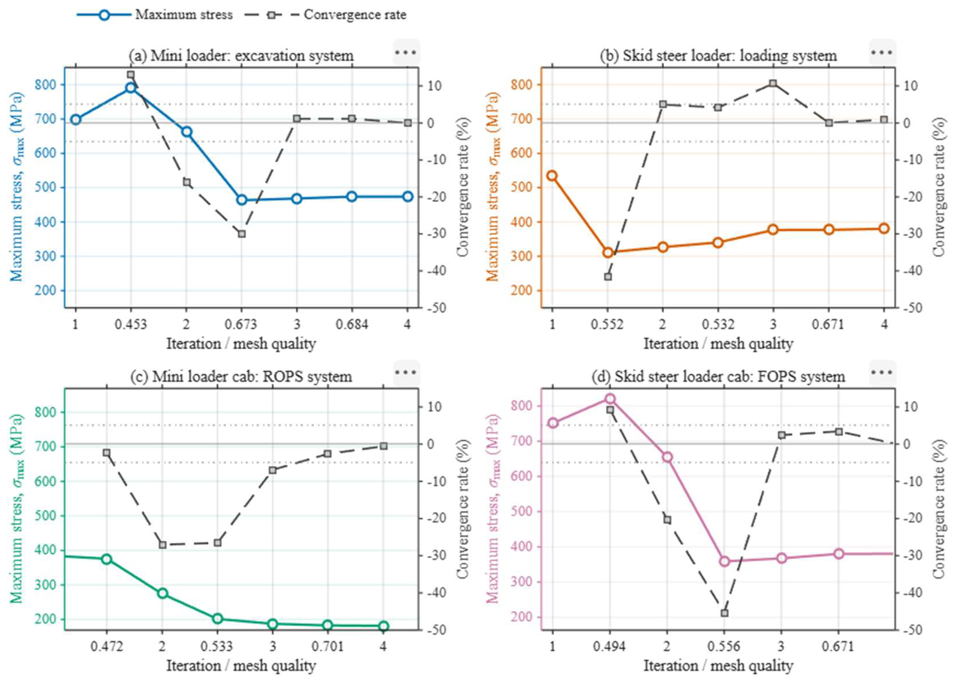
The results of the mesh sensitivity analysis showed that progressive refinement made it possible to stabilize the numerical response of the models and improve the reliability of the simulations in the three evaluated subsystems, as shown in Figure 7. In particular, the convergence achieved with appropriate element sizes and high mesh quality values confirmed that the selected discretization was sufficient to accurately represent the critical zones of effort concentration and deformation, without incurring unnecessary computational cost.
Based on this validation, the final meshing parameters and the main redesign modifications applied to each subsystem were defined and are comparatively summarized in Table 6.

2.6. Load Sensitivity and Uncertainty Analysis

To quantify the effect of the main sources of uncertainty on the loads applied in the FEM, hydraulic pressure, cylinder diameter, rod diameter, bucket efficiency factor, soil shear strength, friction coefficient, contact area, and material yield strength were considered as uncertain variables:
x   =   [ P ,   D ,   d ,   k ,   σ s ,   μ ,   A c , σ y     ]
The relative uncertainty associated with the hydraulic force was estimated using
( u   ·   F h     F h ) = ( μ   · P P ) 2 + ( μ · A A ) 2 + ( μ · n n h ) 2  
For the penetration force, the uncertainty spread was expressed as
( u   ·   F p e n     F p e n ) = ( μ · k k ) 2 + ( μ · σ s σ s ) 2 + ( μ · A c A c ) 2  
These final equations were useful for calculating the uncertainty, as shown in Table 7:
The uncertainty analysis was used to interpret the robustness of the FEM results rather than to redefine the nominal load cases. The largest influence on the applied loads was associated with soil shear strength, contact area, and hydraulic pressure, since these parameters directly affect the soil–tool interaction force and the equivalent load applied to the bucket or cutting edge. In contrast, dimensional tolerances of the cylinder and rod diameters produced smaller variations in the hydraulic force. Therefore, the reported FEM results should be interpreted as nominal responses under the defined operating scenario, while the uncertainty ranges indicate possible variation in the load level around this nominal condition. The convergence behavior of the mesh and the comparison between baseline and optimized models were evaluated using the same nominal load definitions, which ensures that the reported improvements are attributable to the geometric redesign and material substitution rather than to changes in the applied loading conditions.

2.7. Optimization Strategy

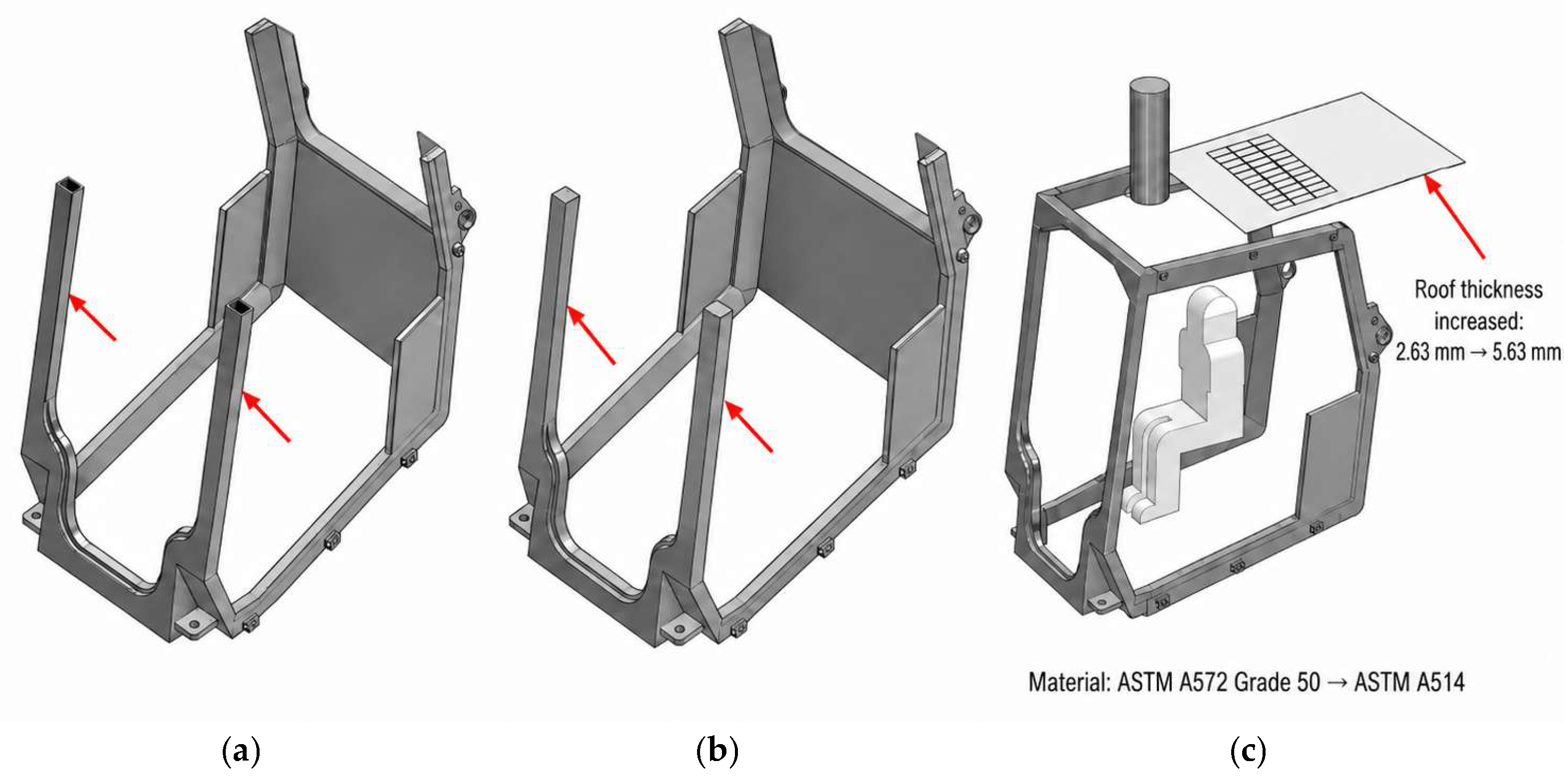
The optimization strategy was specific to each subsystem. In the excavation system, the redesign consisted of increasing the thickness of the bucket connecting plates from 15 mm to 30 mm and replacing the bucket material with Dillidur 450. In the ROPS/FOPS cab, the roof thickness was increased from 2.63 mm to 5.63 mm, the front pillars were redesigned using solid profiles, and the original ASTM A572 Grade 50 steel was replaced with ASTM A514 steel, as shown in Figure 8.
In the charging system, optimization was performed by replacing AISI 1045 with ASTM A514 Grade Q and geometrically redesigning the bucket through the incorporation of 30 mm longitudinal plates at the base and 5 mm internal plates at the joints. The arm was also reinforced by increasing its thickness from 6.5 mm to 7.5 mm and incorporating an additional 3 mm plate in the secondary arm.
To separate the effects of material substitution and geometric reinforcement, each redesign should be interpreted in three stages: baseline geometry/baseline material, baseline geometry/optimized material, and reinforced geometry/optimized material. Because the elastic modulus of the steels used is similar, reductions in deformation are mainly associated with geometric stiffness changes, whereas increases in safety factor are influenced by both effort redistribution and higher yield strength. The added mass was estimated from CAD mass properties as Δm = ρ · ΔV, and the manufacturability of the proposed reinforcements was assessed considering plate cutting, welding access, and compatibility with the original attachment interfaces.

3. Results

3.1. Baseline Structural Performance of the Non-Optimized Subsystems

The structural performance of the excavation, loading, and cab safety systems of the XCMG XC740K skid-steer loader was initially evaluated in its baseline configuration in order to identify critical zones of deformation, effort concentration, and insufficient structural safety levels. In all cases, the results were analyzed using total deformation, von Mises equivalent efforts, and safety factor as comparable indicators between the initial and optimized configurations.

3.1.1. Excavation System

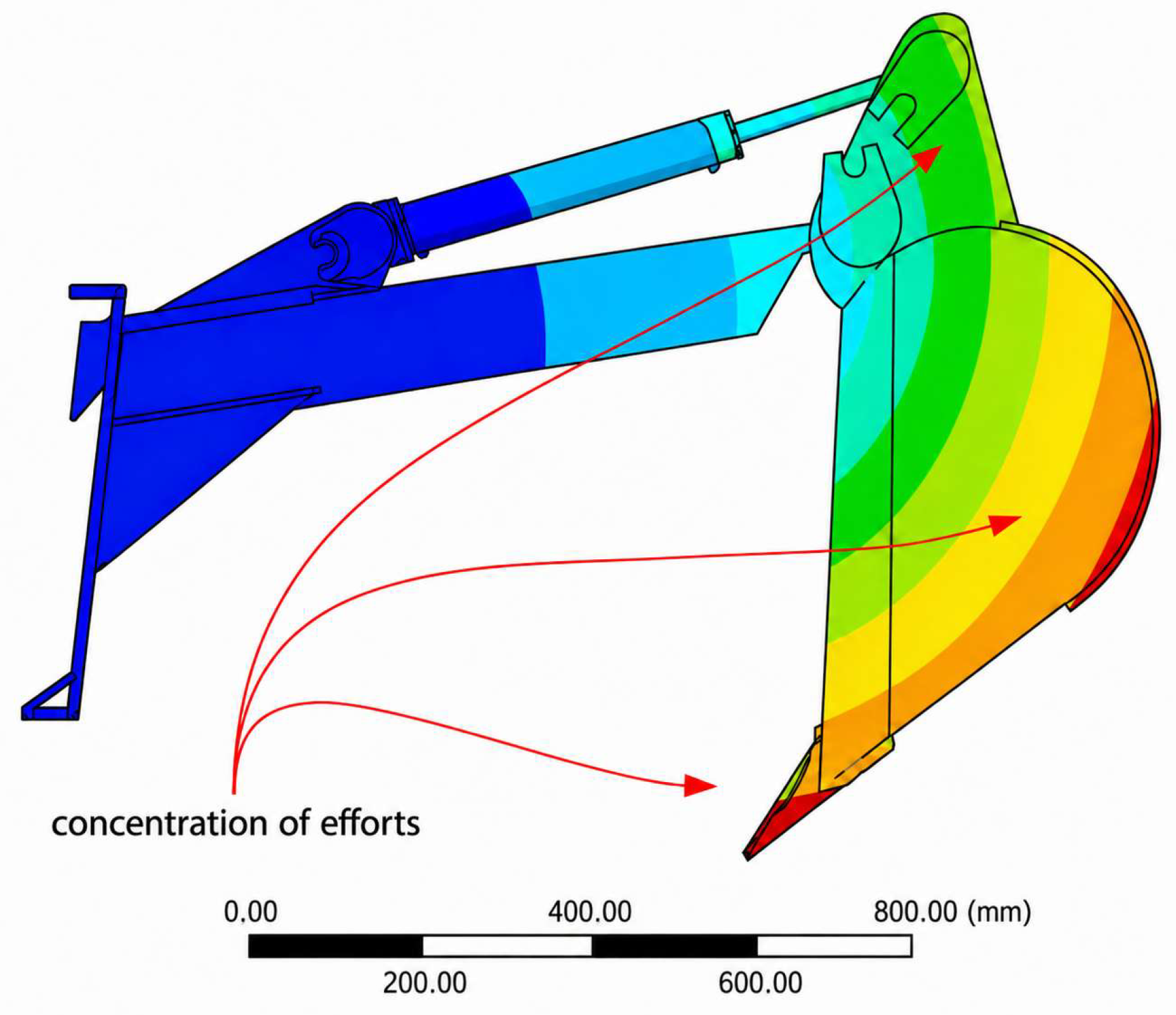
In the initial configuration of the excavation system, the structural simulation showed a maximum deformation of 3.69 mm, concentrated mainly in the cutting tools and at the deepest end of the bucket. The maximum von Mises efforts reached 473.78 MPa, located in the lateral ribs and in the pin support plates (red and orange zones) connecting the hydraulic cylinder and the bucket, as shown in Figure 9. The minimum safety factor obtained was 1.92, with the lowest values occurring in the attachment and load-transfer zones. These results show that although the baseline system does not present immediate failure, the regions of geometric discontinuity and mechanical connection concentrate the most severe structural response of the assembly.

3.1.2. ROPS/FOPS Cab Safety System

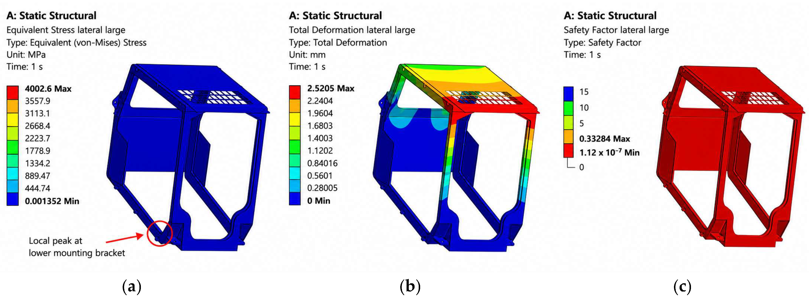
The cab manufactured from ASTM A572 Grade 50 exhibited significant structural deficiencies under the standard evaluation scenarios. In the case of lateral ROPS loading, the maximum deformation was 2.52 mm and the von Mises equivalent efforts reached 4002.6 MPa, a value that greatly exceeds the yield strength of the material; the minimum safety factor was 0.33, as shown in Figure 10.
The apparent combination of a very high von Mises equivalent stress and a relatively small deformation is attributed to the linear-elastic formulation of the baseline ROPS screening analysis and to the highly localized nature of the stress peak. The maximum stress of 4002.6 MPa was located at the lower mounting bracket of the cab, near the fixed-support interface, where a local stiffness discontinuity occurs. Therefore, this value should not be interpreted as a physically sustainable stress state of the entire cab structure, but rather as a localized numerical peak indicating that the original design would experience local yielding or failure in this region under the prescribed lateral ROPS load. In a linear-elastic FEM model, stresses can mathematically exceed the material yield strength without representing plastic redistribution, stiffness degradation, local buckling, or collapse, which explains why the calculated deformation remained close to 2.5 mm. The fixed supports were applied only on the physical mounting surfaces representing the bolted connection to the machine frame, and the lateral ROPS load was applied as a distributed load rather than as a nodal force. In addition, the mesh dependence of this critical region was verified by comparing the last two mesh refinements, for which the maximum stress and the average stress in the critical region varied by less than 5%, consistent with the convergence behavior shown in Figure 7.
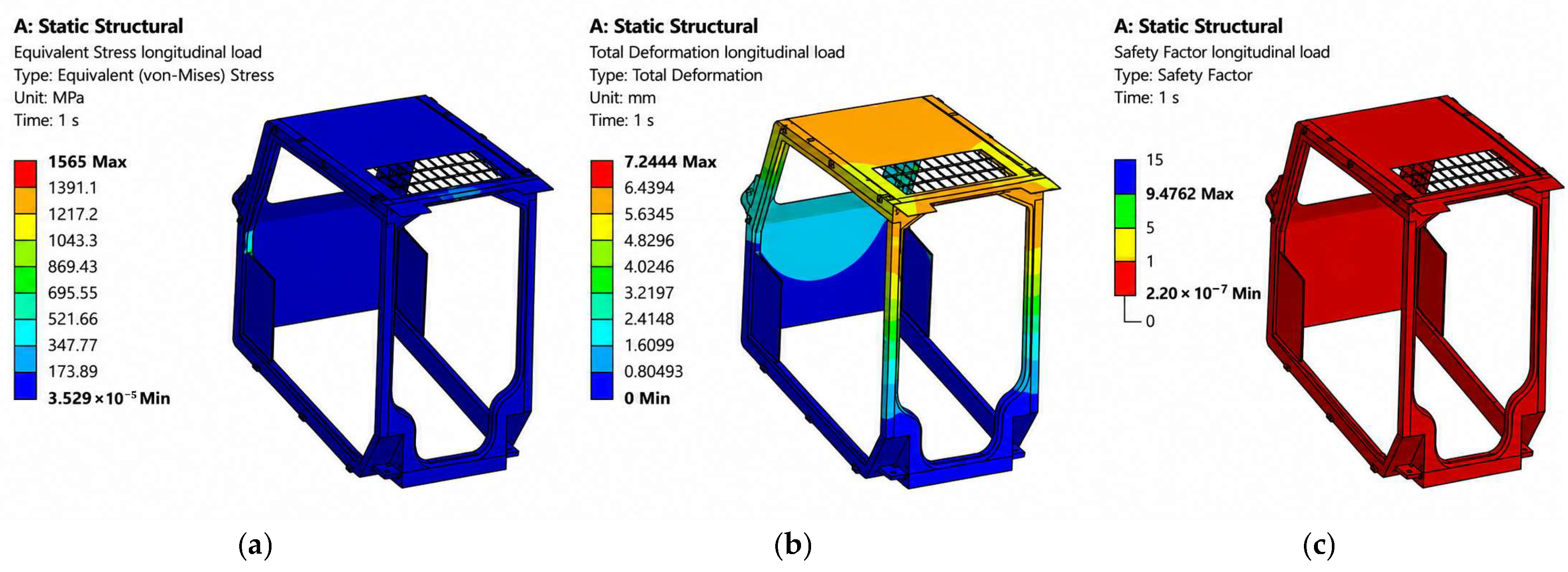
Under longitudinal loading, the maximum deformation recorded was 7.24 mm, with an equivalent effort of 1565 MPa and a safety factor of 0.22, indicating an inadmissible safety performance, as shown in Figure 11.
In the FOPS impact scenario, the maximum efforts with the original material reached 497.98 MPa, also exceeding the expected structural capacity of the baseline cab configuration, as shown in Figure 12. Overall, these results confirm that the original structure does not adequately satisfy the mechanical safety criteria required for operator protection against rollover and overhead impact.

3.1.3. Charging System

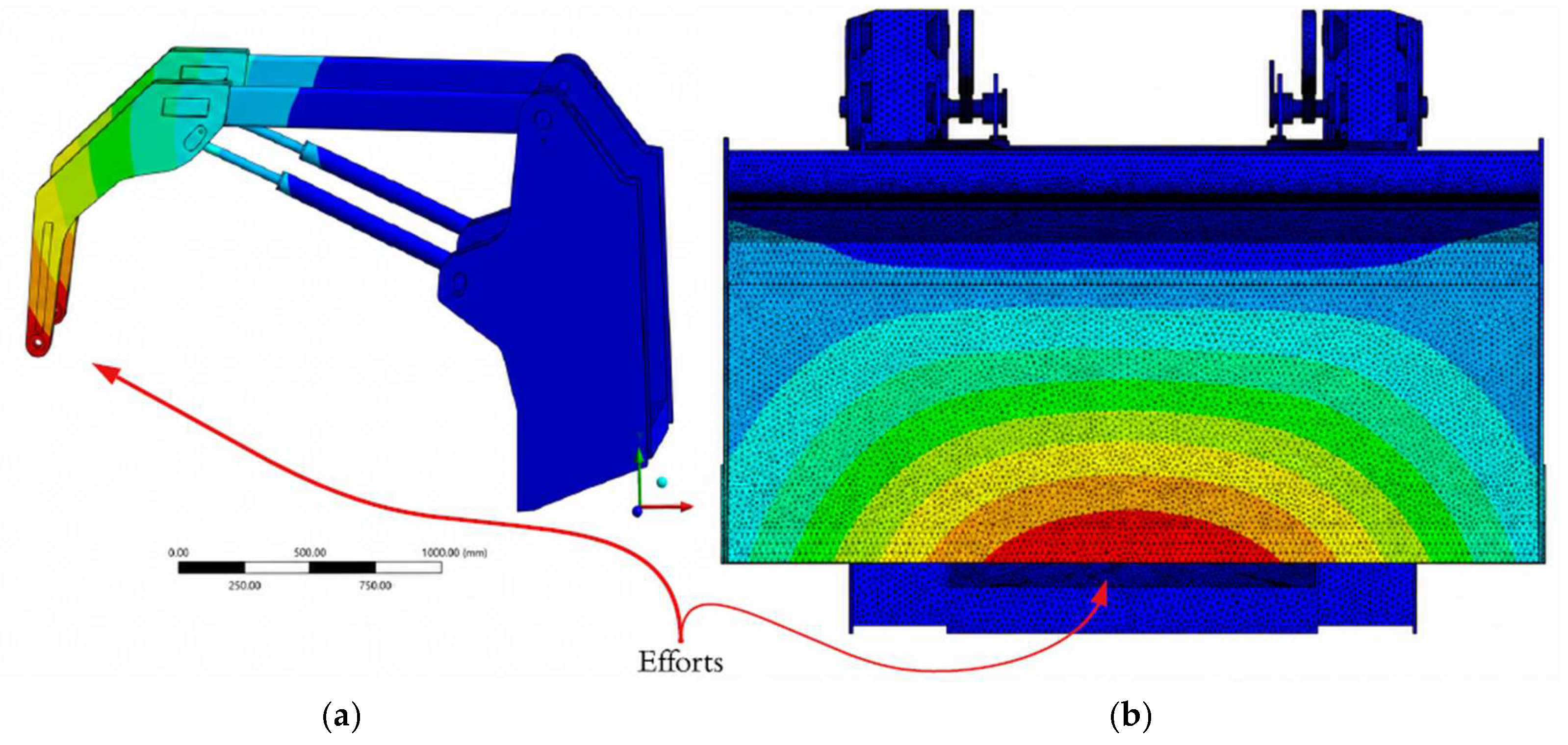
In the charging system, the initial evaluation showed a marked dependence on the material assigned to the bucket. With AISI 1045, the response was unfavorable, with a total deformation of 27.236 mm, an equivalent effort of 576.69 MPa, and a safety factor of 0.84, as shown in Figure 13, indicating an unsafe structural condition under the applied load.

3.2. Baseline Structural Performance of the Optimized Subsystems

After the geometric redesign and strategic material replacement phase, the three subsystems were re-evaluated under the same boundary conditions in order to quantify the improvements achieved in terms of stiffness, effort reduction, and increased safety margin.

3.2.1. Optimized Excavation System

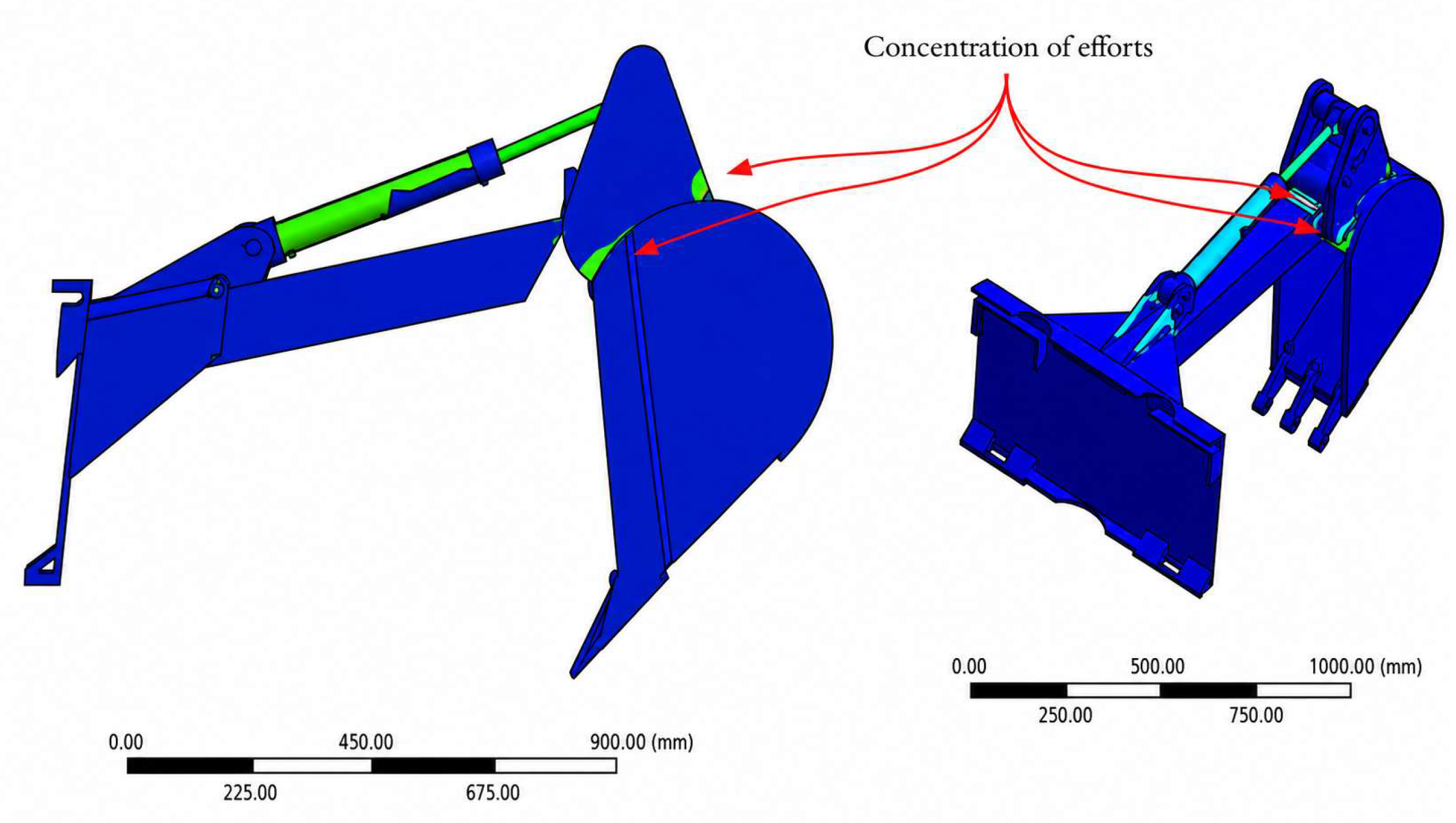
The optimization of the excavation system, based on increasing the thickness of the bucket connecting plates from 15 mm to 30 mm and replacing the bucket material with Dillidur 450, produced consistent structural improvements at both the assembly level and in the critical load-transfer regions. In the complete system, the maximum deformation decreased from 3.69 mm to 3.25 mm, corresponding to a reduction of 11.92%, while the maximum von Mises equivalent stress decreased from 473.78 MPa to 444.66 MPa, representing a reduction of 6.15%. Additionally, the safety factor increased from 1.92 to 2.21, equivalent to an improvement of 15.10%. These results indicate that the redesign improved the stiffness and safety margin of the excavation subsystem without requiring a complete reconfiguration of the assembly, as shown in Figure 14.

3.2.2. Optimized ROPS/FOPS Cab Safety System

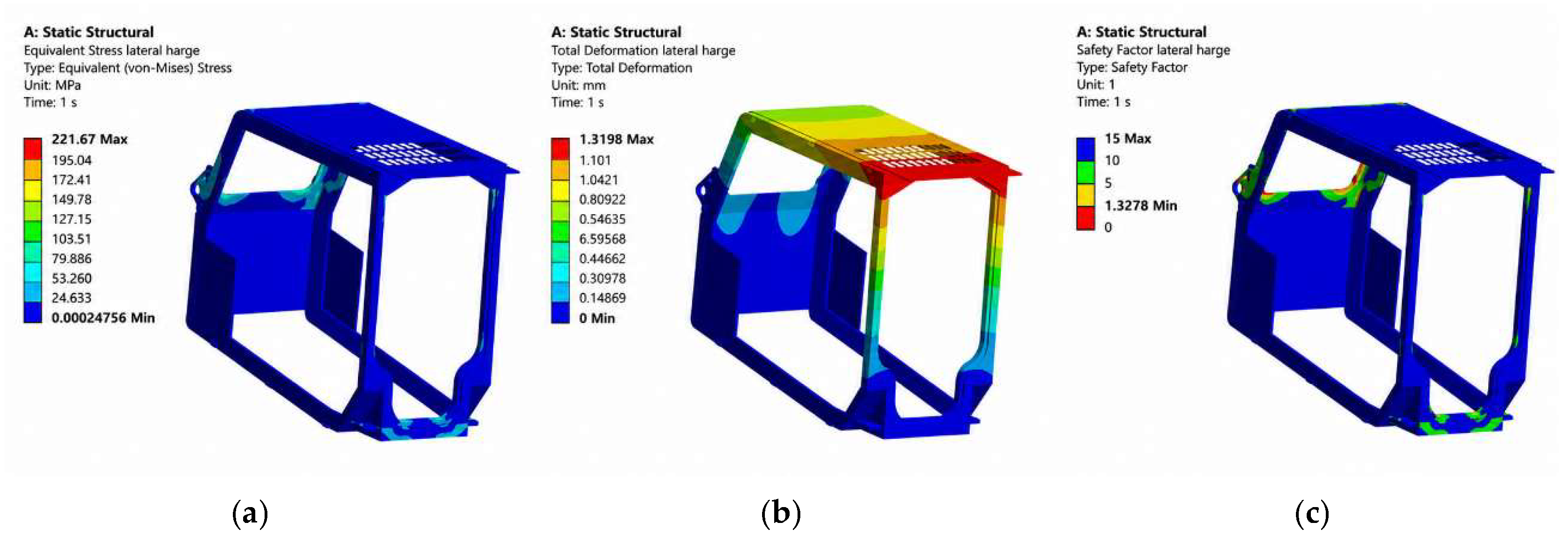
The cab redesign incorporated three main modifications: an increase in roof thickness from 2.63 mm to 5.63 mm, front pillars with solid profiles, and replacement of ASTM A572 Grade 50 steel with ASTM A514. Under lateral ROPS loading, the maximum deformation was reduced to 1.319 mm and the equivalent efforts to 221.67 MPa, with a minimum safety factor of 1.32, as shown in Figure 15.
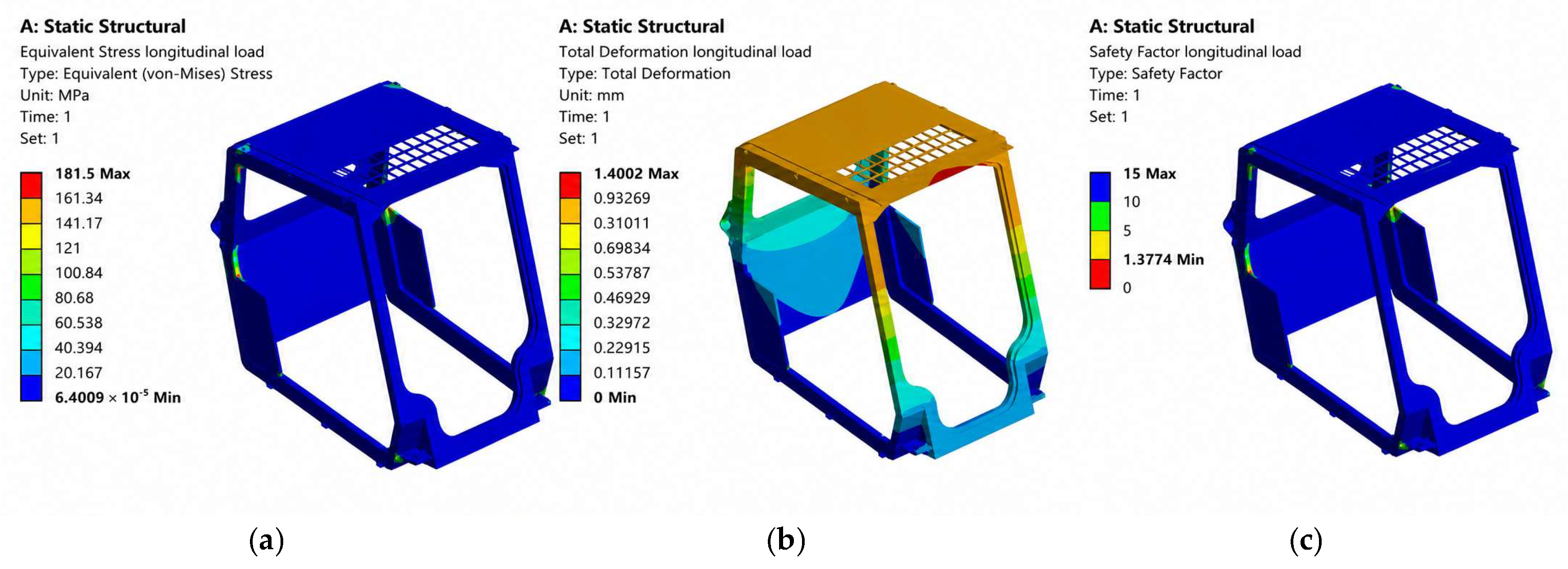
Under longitudinal loading, deformation decreased to approximately 1.40 mm, while the equivalent efforts reached 181.5 MPa and the safety factor increased to 1.38, as shown in Figure 16. In both cases, the maximum efforts remained below the yield strength of ASTM A514, indicating structural behavior compatible with compliance with the safety requirements of the protection system.
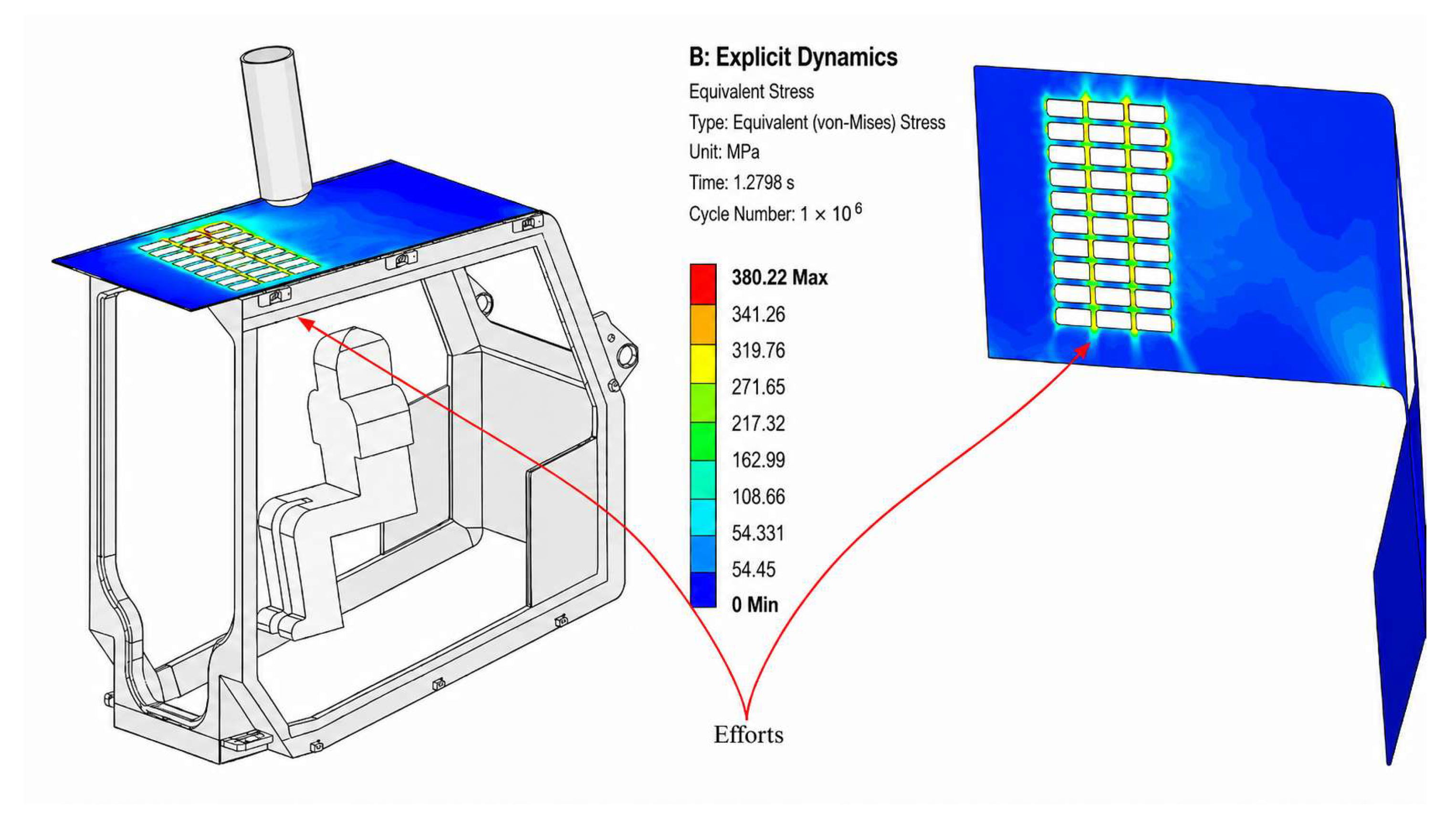
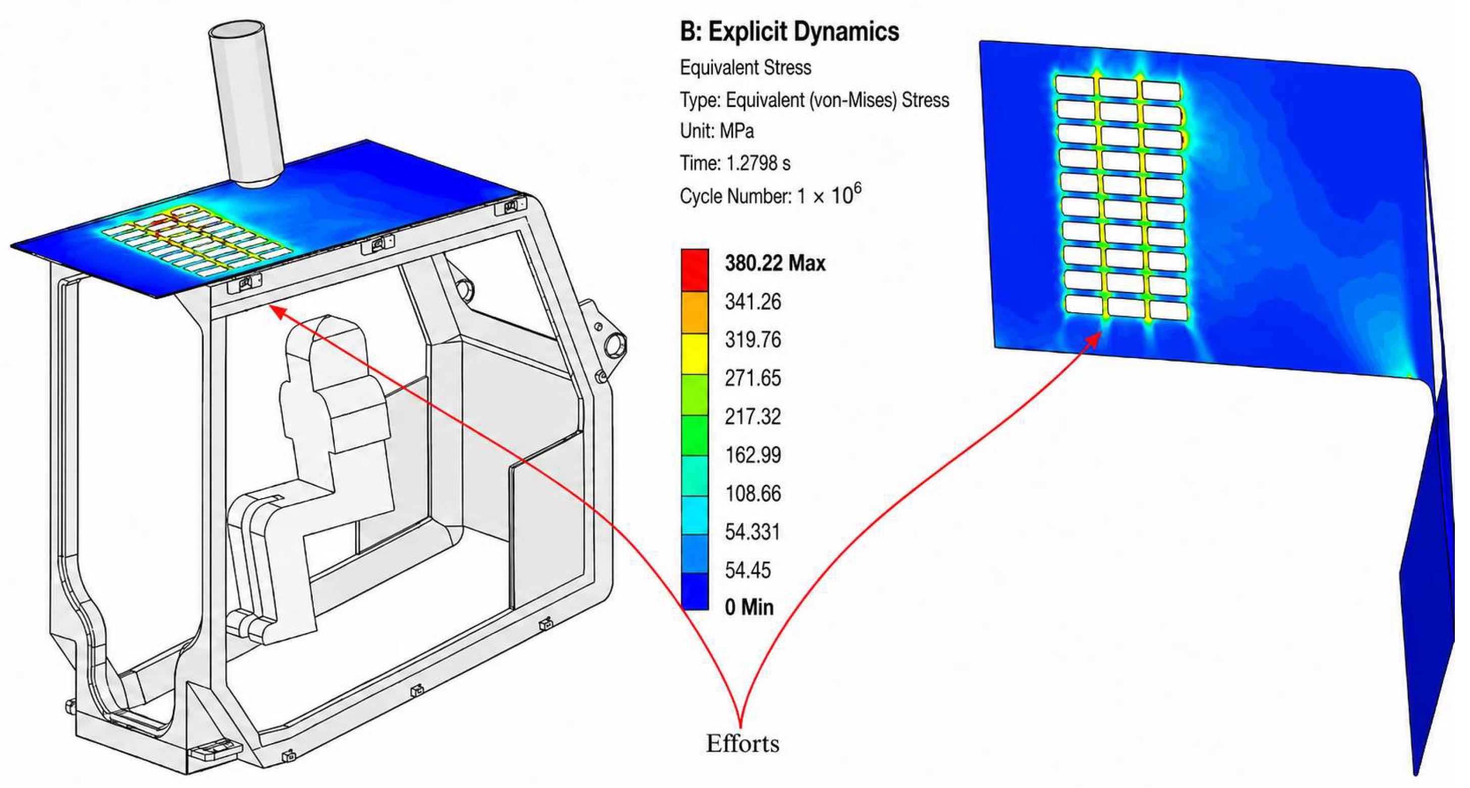
In the FOPS case, the maximum effort recorded with the optimized cab was 380.22 MPa, a value below the yield strength of ASTM A514 (690 MPa), as shown in Figure 17. Although the result remained high, the system response shifted from an inadmissible condition in the baseline configuration to a stable structural condition with no evidence of critical plastic deformation, thereby validating the overall behavior of the cab under the considered standard impact scenario.

3.2.3. Optimized Charging System

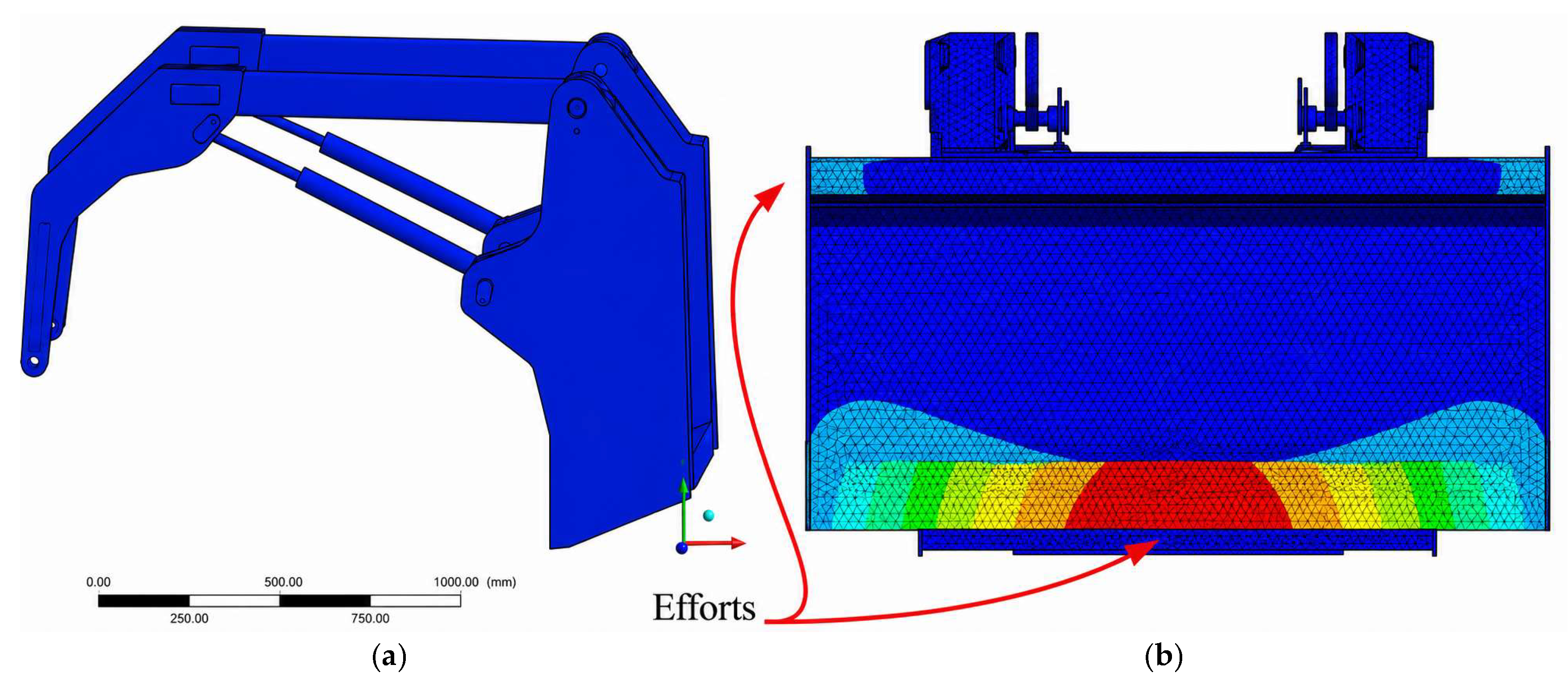
The loading assembly was evaluated at component level to avoid attributing the bucket improvement to the entire subsystem. The optimized bucket made of ASTM A514 Grade Q and reinforced with 30 mm longitudinal plates and 5 mm internal plates showed acceptable behavior, with a maximum deformation of 15.243 mm, von Mises efforts of 233.56 MPa, and safety factor of 2.50. Therefore, the bucket can be considered structurally improved under the simulated load case. However, the arm–quick coupler region remained critical after reinforcement; although deformation decreased from 5.63 mm to 2.77 mm, the local effort level still exceeded the allowable material capacity. Consequently, the complete charging system should be described as partially improved, not fully optimized, as shown in Figure 18.
To clarify the component-level response of the charging system, the optimized results should not be interpreted as a complete structural validation of the entire assembly. The bucket showed the most favorable behavior after the redesign, with maximum deformation decreasing from 27.236 mm to 15.243 mm, von Mises equivalent efforts decreasing from 576.69 MPa to 233.56 MPa, and the safety factor increasing from 0.84 to 2.50. Therefore, the bucket can be considered acceptable under the simulated loading condition. In contrast, the arm–quick coupler region remained the governing critical zone of the loading subsystem. Although the geometric reinforcement reduced deformation at the arm–quick coupler interface, the effort level in this region remained above the allowable material capacity, indicating that additional redesign is still required. Consequently, the complete loading assembly should be interpreted as a system whose global structural safety is controlled by its weakest component, namely the arm–quick coupler interface, rather than as a fully optimized or globally safe subsystem.

3.3. Comparative Summary of Results

Overall, the results show that the optimization strategy was effective in all three subsystems, although with different magnitudes of improvement. The excavation system showed a moderate but consistent improvement in the assembly, with the greatest localized benefit in the bucket; the ROPS/FOPS system shifted from a clearly inadmissible condition to a state compatible with structural safety requirements; and the bucket of the charging system achieved the highest relative improvement in deformation and safety. However, the arm of the charging system remained the most critical component of the study, as it continued to exhibit inadmissible effort levels even after geometric reinforcement. This distribution of results confirms that the comprehensive optimization of heavy machinery must be addressed at both the subsystem and component levels, and not only at the assembly level.

4. Discussion

The results obtained demonstrate that the combination of finite element analysis, localized geometric redesign, and strategic material selection constitutes an effective approach for improving the structural integrity of critical heavy machinery components. Overall, the findings confirm the central hypothesis of the study: the points of greatest structural vulnerability in a compact skid-steer loader can be substantially mitigated when the redesign focuses on the actual load paths and regions with geometric discontinuities; however, some components subjected to severe loading conditions require more aggressive optimization strategies than a simple local increase in thickness or material change.

4.1. Implications of the Redesign of the Excavation System

The excavation system showed a clear structural improvement, especially at the bucket level. The 43.48% reduction in bucket deformation and the 61.82% increase in its safety factor indicate that the increased thickness of the connecting plates and the substitution of the material with Dillidur 450 acted effectively on the main effort concentrators of the subsystem. This result is consistent with the literature identifying joints, connection plates, and regions with abrupt geometric transitions as critical zones for damage initiation [7,8]. In this regard, the results of the present study are aligned with those reported by Yu, Chunlei [10], who achieved a 32.2% reduction in efforts in an excavator boom through thickness increases and local geometric modification. They are also consistent with Sun, Yuan [8], who identified the main effort concentrations in the bucket and its adjacent regions, especially in welds and changes in cross-section.
From a comparative perspective, the effect of the redesign on the excavation system not only confirms the value of localized reinforcement, but also suggests that, in non-conventional configurations, optimization of the ground-contact component may be more decisive than distributed modifications throughout the entire assembly. While previous studies on conventional buckets have reported moderate improvements in deformation, such as the 7.94% reduction documented by Coloma Morales in an excavator bucket [9], in the present work, the reduction in bucket deformation was substantially greater. This difference can be interpreted based on two factors: first, the highly localized nature of the modifications applied; and second, the high structural sensitivity of the single-arm attachment to changes in the stiffness of its connection plates. In other words, the analyzed system appears to respond better to optimization concentrated at critical interfaces than to global oversizing.
Another relevant aspect is that the reduction in the bucket’s equivalent efforts was more limited than the reduction in deformation. This behavior suggests that the redesign mainly improved the overall stiffness and safety margin, but did not completely eliminate all effort concentration zones. From a mechanical standpoint, this is consistent with the fact that maximum efforts in structures with complex geometries do not depend solely on material or thickness, but also on curvature radius, joint quality, and local load transfer [5,8,10]. Therefore, although the results are favorable, the study also shows that the optimization of an excavation system should not be evaluated exclusively by the reduction in deformation, but rather by its ability to redistribute efforts without generating new structural concentrations.

4.2. Structural and Regulatory Relevance of the ROPS/FOPS Redesign

The most critical result of the initial configuration was the behavior of the ROPS/FOPS cab. The presence of efforts of up to 4002.6 MPa in the original ASTM A572 Grade 50 structure, together with safety factors below unity, revealed an inadmissible structural condition and confirmed that the operator protection subsystem constituted the point of greatest vulnerability of the equipment. This finding is especially important because it shifts the discussion from mere structural strength toward regulatory compliance and occupational safety, two dimensions that become central in machinery intended to operate in severe environments [12,13].
The cab optimization made it possible to reverse this condition. Replacing the material with ASTM A514, together with increasing the roof thickness and redesigning the front pillars, led to safety factors of 1.32 and 1.38 under lateral and longitudinal loads, respectively, placing the system within a range compatible with the structural compliance required by ISO 3471 and ISO 3449. This behavior is consistent with studies such as that of Kokot, G. [27], who demonstrated that medium-strength steels are insufficient under severe dynamic events and that high-strength steels provide a better response to plastic deformation and impact [27]. Likewise, the result is aligned with Wetjen, who emphasized that the validation of ROPS/FOPS systems cannot be separated from a strict interpretation of testing standards, since the failure of these structures has direct implications for operator survival [28].
Beyond compliance, the finding has an important methodological implication: in protective structures, optimization cannot focus solely on reducing deformation or mass, but must ensure that the absorbed energy and deformation path do not compromise the operator’s safety volume. In this regard, the present study adds value because it is not limited to comparing materials, but instead integrates geometry, thickness, and high-strength material into a single redesign strategy. This is consistent with studies such as that of Kumar, Uday S., who showed that optimizing cab roofs and front structural members is an effective way to improve the performance of ROPS/FOPS systems [29].
The baseline ROPS model was used as a screening model to identify structural non-compliance. Because the effort values exceed the yield strength of ASTM A572 Grade 50, the linear-elastic solution should not be interpreted as the real post-yield effort state of the cab. In an actual structure, plastic deformation, local buckling, or progressive failure would occur before such elastic efforts could be sustained. Consequently, the safety interpretation was based on the occurrence of yield exceedance, the location of critical regions, the minimum safety factor outside numerical singularities, and the absence/presence of deformation into the deflection-limiting volume, rather than on the absolute singular peak alone.
Moreover, the transition from a clearly unsafe configuration to a structurally admissible condition has evident applied relevance in Latin American contexts, where heavy machinery is frequently operated in infrastructure, mining, and civil construction scenarios with high levels of risk exposure. From this perspective, the result represents not only a mechanical improvement of the component, but also a contribution to preventive design aimed at reducing the risk of serious or fatal injuries.

4.3. Implications of the Charging System Redesign

The response of the bucket confirms that when load paths are relatively well defined and geometric modifications are applied directly to the most highly loaded region, structural redesign can be extremely effective. The incorporation of 30 mm longitudinal plates at the base and 5 mm internal plates made it possible to redistribute the effort flow and substantially increase the stiffness of the component. This behavior is consistent with previous reports showing that relatively simple geometric modifications can multiply the service life of components subjected to repeated loading [30]. Complementarily, materials such as ASTM A514 Grade Q exhibit far superior performance, reinforcing the need to select materials not only based on availability, but also on their ability to simultaneously withstand load, impact, and wear [11].
The response of the charging system first showed a substantial structural improvement in the bucket after optimization. The von Mises equivalent efforts decreased from 576.69 MPa to 233.56 MPa, representing a reduction of 59.50%, while the total deformation decreased from 27.236 mm to 15.243 mm, equivalent to a reduction of 44.03%. As a direct consequence, the safety factor increased from 0.84 to 2.50, that is, an increase of 212.50%. These results demonstrate that the combination of selecting a material with higher load-bearing capacity and improving the component geometry made it possible to transform the bucket from a structurally inadmissible condition into an acceptable mechanical behavior, with a marked reduction in effort severity and a clear improvement in its safety margin. This behavior is consistent with previous studies showing that thickness redistribution and the incorporation of localized reinforcements can significantly modify the load path and structural response of components subjected to severe loading conditions [30].
However, the behavior of the arm–quick coupler highlights the limits of the redesign applied to this subsystem. Although increasing the arm thickness and incorporating a reinforcement plate reduced deformation from 5.63 mm to 2.77 mm, the efforts continued to greatly exceed the material capacity [31]. This behavior suggests that the critical response does not depend solely on a local thickness deficiency, but also on deeper factors associated with the overall structural configuration, the load-transfer path, geometric alignment, and the persistence of severe effort concentrations in regions that were not effectively unloaded. Consequently, the reduction in deformation did not translate into a proportional improvement in the safety factor, indicating that the subsystem cannot be considered structurally robust based solely on increased stiffness. From the perspective of heavy machinery design, this result supports the need to apply multi-objective optimization approaches and, most likely, topological redesigns or more substantial modifications to the load-bearing morphology [3]. In this regard, one of the most relevant contributions of the present work is not only the successful optimization of the bucket, but also the precise identification of the arm–quick coupler as the component that continues to govern the structural vulnerability of the charging system.

4.4. Integrated Discussion: Safety, Durability, and Failure Prevention

Considered as a whole, the three subsystems show that FEA-assisted optimization should not be understood merely as a technique for “reducing efforts,” but rather as a tool for prioritizing the redesign of critical zones, improving regulatory compliance, and preventing premature failures in heavy machinery [3]. The excavation system improved significantly without requiring a complete reconfiguration; the cab shifted from an unsafe condition to one compatible with regulatory requirements; and the bucket of the charging system achieved outstanding structural improvement. These three improvement pathways show that the benefits of the approach are not only mechanical, but also operational and economic, by reducing the likelihood of failure, downtime, and the need for repeated destructive testing [3].
In terms of the working hypothesis, the results support two central ideas. The first is that most structural deficiencies in compact machinery are associated with local effort concentrations and not necessarily with a homogeneous material insufficiency throughout the entire system [5,10]. The second is that the combination of geometric reinforcement and high-strength material is more effective than either of these factors evaluated separately, especially when intervening in components subjected to cyclic loading, impact, or wear is required. This conclusion is consistent with the general framework proposed by studies on mechanical risk, fatigue, and the optimization of welded components in machinery [32,33].
It is also relevant that the study integrated three problems that are usually investigated separately, excavation, loading, and operator protection, within a single platform. This integrated approach constitutes an important methodological contribution because it makes it possible to identify not only which components improve, but also which ones remain structurally limiting for the overall performance of the equipment. In other words, the value of the work is not limited to having optimized individual parts, but rather to having demonstrated how a systematic redesign strategy can map the actual hierarchy of vulnerabilities within a single machine.
The proposed reinforcements increase local mass and may increase manufacturing cost because of high-strength steel procurement, cutting, welding procedure control, and possible preheating requirements. Nevertheless, the modifications are localized and preserve the main mounting interfaces, which favors practical installation. The loading bucket reached acceptable behavior, but the arm–quick coupler region remained critical; therefore, the loading assembly should be considered partially improved rather than fully optimized.

4.5. Limitations and Future Research Lines

Despite the positive results, the study presents limitations that must be explicitly acknowledged. First, part of the simulations was developed within a static structural framework, which simplifies the representation of real dynamic phenomena associated with repeated impacts, vibrations, operator maneuvers, and transient loads in the hydraulic system. Second, the absence of original manufacturer drawings required the use of reverse engineering, introducing residual geometric uncertainty, although high-resolution 3D scanning was employed. Third, a complete experimental validation of the structural redesigns through physical testing was not incorporated; therefore, final confirmation of performance under real service conditions should be considered a necessary future stage.
Based on this, future research lines should be oriented in at least four directions. First, a more aggressive optimization of the arm and quick coupler should be developed, possibly incorporating topological changes, section redesign, or materials with higher specific capacity. Second, dynamic loads and fatigue analysis should be integrated, especially in components subjected to repeated excavation and loading cycles. Third, the model should be complemented with experimental validation, either through strain-gauge measurements, controlled testing, or correlation with real operational signals. Fourth, progress should be made toward multi-objective optimization schemes that integrate mass, manufacturability, cost, service life, and operator safety within a single decision-making framework. In this regard, the present work establishes a solid basis for a second stage of research aimed not only at improving components, but also at building a transferable methodology for the structural redesign of compact heavy machinery in severe operating contexts.

5. Conclusions

The present study demonstrated that finite element analysis-assisted structural optimization is an effective strategy for evaluating and redesigning critical components of an XCMG XC740K skid-steer loader, integrating the excavation system, charging system, and ROPS/FOPS cab safety structure within a single platform. The methodology based on reverse engineering, CAD modeling, standards-based load definition, and numerical simulation made it possible to accurately identify the zones of greatest effort concentration and establish design interventions aimed at improving the structural integrity and operational safety of the equipment.
In the excavation system, increasing the thickness of the bucket connecting plates and replacing the material with Dillidur 450 produced a consistent structural improvement. Bucket deformation was reduced by 43.48%, and its safety factor increased by 61.82%, while the complete system showed an 11.92% decrease in deformation and a 15.10% increase in safety factor. These results confirm that the localized redesign of critical load-transfer zones is an effective strategy for reducing the structural vulnerability of the excavation subsystem.
In the safety cab, the original configuration manufactured from ASTM A572 Grade 50 exhibited inadmissible effort levels and safety factors below unity under the ROPS and FOPS scenarios, revealing an inadequate structural condition for operator protection. After the redesign, which included increasing the roof thickness, geometrically modifying the front pillars, and replacing the material with ASTM A514, the structure achieved safety factors of 1.32 and 1.38 under lateral and longitudinal loads, respectively, while also keeping the FOPS efforts below the yield strength of the optimized material. Consequently, the proposed redesign made it possible to bring the cab to a condition compatible with the structural safety requirements established by the applied standards.
In the charging system, the bucket showed the greatest structural improvement after optimization. The redesign reduced the von Mises equivalent efforts from 576.69 MPa to 233.56 MPa, representing a 59.50% decrease, and reduced the maximum deformation from 27.236 mm to 15.243 mm, equivalent to a 44.03% reduction. As a result, the safety factor increased from 0.84 to 2.50, indicating that the bucket changed from an inadmissible structural condition to an acceptable mechanical response under the simulated loading scenario. However, this improvement should be interpreted at the component level, since the complete loading assembly is still governed by the arm–quick coupler interface, which remains the critical region and requires further redesign.
In general terms, the main contribution of this work lies in demonstrating that the integration of FEM simulation, geometric redesign, and material selection makes it possible not only to improve the structural performance of specific components, but also to build a transferable methodology for failure prevention in compact heavy machinery. As a future research line, it is recommended to further optimize the arm and quick coupler through more advanced approaches, including fatigue analysis, dynamic loads, experimental validation, and multi-objective strategies that integrate safety, mass, manufacturability, and service life.


Author Contributions

Conceptualization, D.A.D.-S. and X.N.; methodology, D.A.D.-S., G.M. and J.J.M.-C.; software, G.M., J.J.M.-C. and X.N.; validation, D.A.D.-S., G.M. and J.J.M.-C.; formal analysis, D.A.D.-S., G.M. and J.J.M.-C.; investigation, D.A.D.-S., X.N., G.M. and J.J.M.-C.; resources, G.M., J.J.M.-C. and X.N.; data curation, D.A.D.-S., X.N., G.M. and J.J.M.-C.; writing—original draft preparation, J.J.M.-C., G.M. and X.N.; writing—review and editing, D.A.D.-S.; visualization, G.M., J.J.M.-C. and X.N.; supervision, D.A.D.-S., G.M. and J.J.M.-C.; project administration, D.A.D.-S.; funding acquisition, D.A.D.-S. All authors have read and agreed to the published version of the manuscript.

Funding

This research received no external funding.

Data Availability Statement

The raw data supporting the conclusions of this article will be made available by the authors on request.

Conflicts of Interest

The authors declare no conflicts of interest.

References

  1. Vásconez, M.; Profesor, C.; Leonardo, M.; León, T. Revista Estudios del Desarrollo Social: Cuba y América Latina Minería en el Ecuador: Sostenibilidad y licitud Mining in Ecuador: Sustainability and Lawfulness. In Estudios del Desarrollo Social: Cuba y América Latina RPNS; University of Havana: La Habana, Cuba, 2018; Volume 6, Available online: https://revistas.uh.cu/revflacso (accessed on 15 March 2026).
  2. Kim, S.; Lee, J.; Kang, C. Analysis of Industrial Accidents Causing Through Jamming or Crushing Accidental Deaths in the Manufacturing Industry in South Korea: Focus on Non Routine Work on Machinery. Saf. Sci. 2021, 133, 104998. [Google Scholar] [CrossRef]
  3. Sivitski, A.; Põdra, P. Machinery Risk Assessment Integration with Design and Development Methods for Risk and Potential Failure Reduction Considering Safety and Efficiency. AIP Conf. Proc. 2024, 2989, 030013. [Google Scholar] [CrossRef]
  4. Dyorina, N.V.; Velikanov, V.S.; Dyorina, K.S. Identification of Failure Patterns of Excavator Equipment Failures Considering the Control Factor. IOP Conf. Ser. Mater. Sci. Eng. 2020, 971, 042062. [Google Scholar] [CrossRef]
  5. Pettersson, G.; Barsoum, Z. Finite Element Analysis and Fatigue Design of a Welded Construction Machinery Component Using Different Concepts. Eng. Fail. Anal. 2012, 26, 274–284. [Google Scholar] [CrossRef]
  6. Patel, B.P.; Prajapati, J.M. A Revies on Fea and Optimization of Backhoe Attachment in Hydraulic Excavator. IACSIT Int. J. Eng. Technol. 2011, 3, 505–511. [Google Scholar] [CrossRef]
  7. Biradar, S.A.; Kotturshettar, B.B.; Vernekar, G.N.; Biradar, B.A. Design, Analysis and Optimization of Heavy Duty Excavator bucket by Using Finite Element Analysis. Int. J. Sci. Dev. Res. 2018, 3, 74–83. Available online: www.ijsdr.org (accessed on 15 March 2026).
  8. Sun, Y.; Wang, Y.; Wang, L.; Li, C.; Tang, L.; Wang, D.; Ma, R.; Xue, Z.; Wei, X.; Cui, M.; et al. Digging Performance and Efforts Characteristic of the Excavator Bucket. Appl. Sci. 2023, 13, 11507. [Google Scholar] [CrossRef]
  9. Morales, S.A.C. Simulación de Recuperación Por Método de Elemento Finito de Cucharones Para Maquinaria de Minería; Escuela Superior Politécnica de Chimborazo: Riobamba, Ecuador, 2017. [Google Scholar]
  10. Yu, C.; Bao, Y.; Li, Q. Finite element Analysis of Excavator Mechanical Behavior and Boom Structure Optimization. Measurement 2021, 173, 108637. [Google Scholar] [CrossRef]
  11. Alshboul, O.; Shehadeh, A.; Tatari, O.; Almasabha, G.; Saleh, E. Multiobjective and Multivariable Optimization for Earthmoving Equipment. J. Facil. Manag. 2022, 22, 21–48. [Google Scholar] [CrossRef]
  12. ISO 3471:2008; Earth Moving Machinery Roll Over Protective Structures Laboratory Eests and Performance Requirements. International Organization for Standardization: Vernier, Switzerland, 2008. Available online: https://standards.iteh.ai/catalog/standards/sist/ (accessed on 15 March 2026).
  13. ISO 3449:2005; Earth Moving Machinery Falling Object Protective Structures Laboratory Tests and Performance Requirements. International Organization for Standardization: Vernier, Switzerland, 2005. Available online: https://standards.iso.org/iso/ (accessed on 15 March 2026).
  14. ISO 6015:2006; Earth Moving Machinery Hydraulic Excavators and Backhoe Loaders Methods of Determining Tool Forces. International Organization for Standardization: Vernier, Switzerland, 2006.
  15. J296_199901; SAE. J296 Excavator, Mini-Excavator and Backhoe Hoe Bucket Volumetric Rating. SAE International: Warrendale, PA, USA, 1999.
  16. ISO:6165; Earth Moving Machinery Basic Types Identification and Terms and Definitions. International Organization for Standardization: Vernier, Switzerland, 2012.
  17. Duque-Sarmiento, D.A.; Baño-Morales, D.A. Assessment of Hydraulic Oil Properties During Operation of a Mini Loader. Lubricants 2024, 12, 320. [Google Scholar] [CrossRef]
  18. Xuzhou Construction Machinery Group Co. Manual XCMG (XC740K_XC750K_XC760K_XC770K) Skid Steer Loader; Xuzhou Construction Machinery Group Co.: Xuzhou, China, 2023. [Google Scholar]
  19. ANSYS Inc. ANSYS Workbench/Mechanical 2024 R1, May 20, 2024; ANSYS, Inc.: Canonsburg, PA, USA, 2024; R1. [Google Scholar]
  20. Emco Group UK. Creaform Academia 50/Go!SCAN 50–3D Scanner; Emco Group UK: Derby, UK, 2025. [Google Scholar]
  21. SSAB. Hardox® 450—Explore Steel Properties & Benefits. Available online: https://www.ssab.com/en/brands-and-products/hardox/product-program/450 (accessed on 15 March 2026).
  22. MatWeb, L. MatWeb: The Online Materials Information Resource. Available online: https://www.matweb.com (accessed on 15 March 2026).
  23. Hibbeler, R.C. Mecánica de Materiales, Octavo; Pearson Educación: Naucalpan, México, 2011. [Google Scholar]
  24. Caterpillar. Caterpillar Performance Handbook; Caterpillar: Peoria, IL, USA, 2022. [Google Scholar]
  25. Society Automotive Engineering. SAE J1040: Performance Criteria for Rollover Protective Structures (ROPS) for Construction, Earthmoving, Forestry and Mining Machines. SAE 1994, 29, 1–9. [Google Scholar] [CrossRef]
  26. ISO 3164:2013; Earth Moving Machinery Laboratory Evaluations of Protective Structures Specifications for Deflection Limiting Volume. International Organization for Standardization: Vernier, Switzerland, 2013. Available online: https://standards.iteh.ai/catalog/standards/sist/ (accessed on 15 March 2026).
  27. Kokot, G.; Ogierman, W. The Numerical Simulation of FOPS and ROPS Tests using LS-DYNA. Mechanika 2019, 25, 383–390. [Google Scholar] [CrossRef]
  28. Wetjen, R.D.; Deere, J.; Works, D.; Milwaukee, W. Testing ROPS and FOPS for Safety Compliance Off-Highway Vehicle Meeting Testing ROPS and FOPS for Safety Compliance; SAE International: Milwaukee, WI, USA, 2026. [Google Scholar]
  29. Kumar, U.S.; Rudresh, M.; Maruthi, B.H. Design Optimization of CAB Roof for Rops and Fops Failure. Int. J. Adv. Eng. Manag. 2014, 1, 1–12. Available online: https://www.researchgate.net/publication/372164945_Design_Optimization_of_CAB_Roof_for_Rops_and_Fops_Failure (accessed on 15 March 2026).
  30. Tang, T.; Wang, L.; Zhu, M.; Zhang, H.; Dong, J.; Yue, W.; Xia, H. Topology Optimization: A Review for Structural Designs Under Statics Problems. Materials 2024, 17, 5970. [Google Scholar] [CrossRef] [PubMed]
  31. Zemlik, M.; Konat, Ł.; Leśny, K.; Jamroziak, K. Comparison of Abrasive Wear Resistance of Hardox Steel and Hadfield Cast Steel. Appl. Sci. 2024, 14, 11141. [Google Scholar] [CrossRef]
  32. Hsieh, C.C.; Hung, C.C.; Hsiao, T.J.; Li, T.C. Finite Element Analysis Applied to the Taper Mechanism of Excavator Assembly Alignment Analysis and Optimization. Eng. Fail. Anal. 2021, 121, 105170. [Google Scholar] [CrossRef]
  33. Padmanaban, G.; Balasubramanian, V. Multiobjective and Multivariable Optimization for Hardfacing Process Parameters. J. Manuf. Technol. Manag. 2011, 22, 21–38. [Google Scholar]
Figure 1. XCMG XC740K skid-steer loader as the experimental platform.
Machines 14 00833 g001
Figure 2. Integrated methodological workflow of the study.
Machines 14 00833 g002
Figure 3. Reverse engineering process. (a) Skid-steer loader and scanning software, (b) scanning of the charging system and ROPS/FOPS cab, and (c) scanning of the excavation system.
Machines 14 00833 g003
Figure 4. CAD modeling of the critical subsystems. (a) Cab, (b) arm–bucket system, and (c) excavation system.
Machines 14 00833 g004
Figure 5. Boundary conditions. (a) Fixed supports and bracing in an excavation system, (b) load-bearing elements and fixed supports, (c) cab mounting brackets and supports.
Machines 14 00833 g005
Figure 6. Mesh sensitivity analysis of skid-steer loader structures.
Machines 14 00833 g006
Figure 7. Mesh convergence in the skid-steer loader. (a) Excavation system, (b) charging system, (c) ROPS system, (d) FOPS system.
Machines 14 00833 g007
Figure 8. (a) Standard cab, (b) cab with reinforced ROPS posts, and (c) cab with reinforced FOPS roof.
Machines 14 00833 g008
Figure 9. Focusing efforts on the excavation system.
Machines 14 00833 g009
Figure 10. Side-loading cab (ROPS): (a) von Mises efforts, (b) total deformation, (c) safety factor.
Machines 14 00833 g010
Figure 11. Cab under longitudinal load (ROPS): (a) von Mises efforts, (b) total deformation, (c) safety factor.
Machines 14 00833 g011
Figure 12. Cab (FOPS) subjected to impact via explicit dynamics.
Machines 14 00833 g012
Figure 13. Unoptimized charging system: (a) arm, (b) bucket.
Machines 14 00833 g013
Figure 14. Effort concentration in the optimized excavation system.
Machines 14 00833 g014
Figure 15. Optimized side-loading cab (ROPS): (a) von Mises efforts, (b) total deformation, (c) safety factor.
Machines 14 00833 g015
Figure 16. Cab with optimized longitudinal load (ROPS): (a) von Mises efforts, (b) total deformation, (c) safety factor.
Machines 14 00833 g016
Figure 17. Optimized cab (FOPS) exposed to impact through explicit dynamics.
Machines 14 00833 g017
Figure 18. Optimized charging system: (a) arm, (b) bucket.
Machines 14 00833 g018
Table 1. Experimental platform and general parameters of the study.
ElementValue
Core teamSkid-steer loader
Team standingsNorma ISO 6165
Operating weight (load/excavation)2950 Kg
Operating weight used in ROPS/FOPS3140 kg
System hydraulic pressure210 bar
Maximum starting torque≥22 kN
Maximum tensile strength≥25 kN
Front loader capacity0.45 m3
Bucket capacity0.06 m3
Table 2. Equipment and software used in the study.
EquipmentBrand/SupplierModel/VersionApplication
Skid-steer loaderXCMGXC740K (2023)Experimental platform
3D scannerCreaformGoScan 50Geometric survey
Scanning softwareCreaformVXElements 10.2.33D processing and reconstruction
CADAutodeskInventor Professional 2025Parametric modeling
CAEANSYSWorkbench/Mechanical 2024 R1FEM simulation
Table 3. Mechanical properties and application of the materials used.
MaterialMain ApplicationYoung’s Modulus (GPa)Poison CoefficientDensity (g/cm3)Elastic Limit (MPa)Ultimate Resistance (MPa)
AISI 1045Excavation and charging system, base configuration2050.297.87485620
ASTM A572 GRADO 50ROPS/FOPS cab, base configuration1600.297.80345450
ASTM A514 GRADO QCharging system, optimized configuration2050.297.85690838
ASTM A514ROPS/FOPS cab, optimized configuration2050.297.85690828
DILLIDUR 450Excavation system, optimized configuration2100.297.8511001250
Table 4. Input parameters and final loads applied in the FEM models.
ParameterSymbolValueUnitSource
Hydraulic pressureP21MPaManufacturer
Cylinder bore diameter—excavationD0.050mMeasurement
Rod diameter—excavationd0.028mMeasurement
Rod diameter—loading cylinderd_L0.035mMeasurement
Hydraulic efficiencyη1.00-Hydraulic-force calculation
Bucket capacityVc0.06m3Manufacturer
Bucket efficiency factork0.7-Operational criteria
Soil shear strength, wet clay σ s 0.3MPaWet clay
Soil–metal friction coefficientμ0.5-Wet clay
Critical arm lengthLb 1.10424mMeasurement
Gravityg9.81m/s2Constant
Resultant cutting-edge forceF28,856.1NLoading-system FEM
Horizontal componentF_x = F · cos 45°20,404.4NFEM load component
Vertical componentF_y = F · sin 45°20,404.4NFEM load component
Table 5. Regulations, primary loads, and types of analysis by subsystem.
SubsystemTheoretical/Regulatory FrameworkVariables/Principal LoadingsType of Analysis
ExcavationISO 6015; SAE J296; Terzaghi; material strengthPenetration force, grip force, pull-out force, tear force, bending moment, and shear efforts; bucket capacity 0.06 m3Structural statics
LoadHydraulic parameters of the equipment; safety design criteriaDistributed load of 28,856.1 N applied to the edge at a 45° angle; fixed supports; efforts 21 MPaStructural statics
Rollover protective structure (ROPS)SAE J1040; ISO 347118,840 N lateral; 61,575.4 N vertical; 15,103.4 N longitudinal; 4,710 JStructural statics
Falling-over protective structure (FOPS)ISO 3449; ISO 3164227 kg; 10 m; 22,270 J; 14 m/s; 3 sExplicit dynamics
Table 6. Mesh strategy and redesign by subsystem.
SubsystemMesh ParametersNumber of ElementsNumber of NodesVariables EvaluatedRedesign Changes
ExcavationFinal element size of 5 mm, mesh quality of 0.824 using the Element Quality metric, and convergence of results below 5% achieved after seven simulation iterations.24.555.4775.431.892Deformation, von Mises efforts, safety factorConnecting plates increased from 15 mm to 30 mm; bucket made of Dillidur 450.
LoadFinal element size of 6 mm, mesh quality of 0.834 using the Element Quality metric, and convergence of results below 5% achieved after seven simulation iterations.10.130.2492.240.902Deformation, von Mises efforts, safety factorBucket: 30 mm longitudinal plates and 5 mm internal plates; excavation arm increased from 6.5 mm to 7.5 mm; 3 mm plate and material change to ASTM A514 Grade Q.
ROPS/FOPSFinal element size of 10 mm; using a surface-based method, a mesh quality of 0.961 was obtained according to the Element Quality metric, and convergence of results below 5% was achieved after seven simulation iterations.5.876.7961.334.028Deformation, von Mises efforts, safety factorCab roof thickness increased from 2.63 mm to 5.63 mm; solid pillars; material changed to ASTM A514.
Table 7. Variables considered in the uncertainty analysis.
VariableSymbolFace ValueRangeJustification
Hydraulic pressureP21 MPa±5%Operational variation
Cylinder bore diameter—excavationD0.050 m±0.5 mmDimensional tolerance
Rod diameter—excavationd0.028/0.025 m±0.5 mmDimensional tolerance
Bucket efficiency factork0.70.65–0.85Operating condition
Soil shear strength, wet clayσs 0.3 MPa±30%Geotechnical variability
Soil–metal friction coefficientμ0.5–0.7±20%Soil–metal variability
Contact informationAc According to CAD±5%Geometric/contact error
Elastic limitσy Depends on the material±5%Material variability
Disclaimer/Publisher’s Note: The statements, opinions and data contained in all publications are solely those of the individual author(s) and contributor(s) and not of MDPI and/or the editor(s). MDPI and/or the editor(s) disclaim responsibility for any injury to people or property resulting from any ideas, methods, instructions or products referred to in the content.