Article

Multi-Physics Study of Hairpin Winding Cooling Systems in Less-Rare-Earth Permanent Magnet Traction Motors


by
Ali Zarghani
1,2,
Peter Sergeant
1,2 and
Mohamed N. Ibrahim
1,2,3,*
1
Department of Electromechanical, Systems, and Metal Engineering, Ghent University, 9052 Gent, Belgium
2
FlandersMake@UGent—Corelab MIRO, 3001 Leuven, Belgium
3
Department of Electrical Engineering, Kafrelshiekh University, Kafr El-Sheikh 33511, Egypt
*
Author to whom correspondence should be addressed.
Machines 2026, 14(7), 776; https://doi.org/10.3390/machines14070776
Submission received: 15 June 2026 / Revised: 8 July 2026 / Accepted: 9 July 2026 / Published: 10 July 2026
(This article belongs to the Special Issue Wound Field and Less Rare-Earth Electrical Machines in Renewables)

Abstract

Hairpin windings are increasingly adopted in permanent magnet (PM) traction machines owing to their high slot fill factor, compact end-winding structure, and suitability for automated manufacturing. However, limited heat dissipation and high copper losses under peak loading and high-frequency operation result in severe thermal constraints, which restrict the power rating of the machine. This paper presents a multi-physics comparison of different winding cooling topologies for a PM machine with hairpin winding, including hollow conductor cooling, end-winding cooling, and cooling channel insertion at slot-bottom, slot-middle, and slot-opening regions. A coupled electromagnetic–thermal model based on the finite element method (FEM), which accounts the heat transfer between different components, is used to analyze temperature distribution, losses, efficiency, loading capacity, and hydraulic requirements. The results show that the position of the cooling channel has great influence on the thermal behavior and electromagnetic performance of the machine under different working conditions. The study emphasizes the strong coupling between cooling design, conductor geometry, AC loss behavior, and efficiency and provides practical design guidelines for selecting appropriate cooling techniques in high-power-density traction machines. Consequently, an improved cooling system results in a reduced amount of PM for the same output power range.

1. Introduction

The increasing demand for compact, lightweight, and high-efficiency electric propulsion systems has accelerated the development of high-power-density traction motors for electric vehicles, aerospace, and advanced transportation systems [1,2,3,4,5]. Permanent magnet (PM) machines are considered one of the most attractive solutions because of their high torque density, wide constant-power operating range, and superior efficiency [6]. However, the continuous increase in power density and operating speed has led to increased thermal loading within electrical machines, making thermal management one of the main design challenges. High temperatures not only lower efficiency but also speed up insulation aging, reduce reliability, and ultimately limit the continuous power capability [7,8].
The winding is generally the main source of heat generation in electrical machines because of copper losses. Therefore, the thermal behavior of the winding has a direct influence on the machine performance, lifetime, and overload capability [9]. The hairpin winding technology has gained considerable attention in recent years for the automotive traction applications due to its high slot fill factor, compact end-winding geometry, and suitability for automated mass production [9,10]. Rectangular conductors improve copper utilization in the slot, leading to a reduction in DC resistance and enabling a higher electric loading and torque density compared to conventional stranded windings [11,12]. Despite these advantages, the hairpin windings present several electromagnetic and thermal challenges. The relatively large conductor dimensions increase the skin and proximity effects, which result in large AC copper losses, especially in high-speed operation [13]. Moreover, the AC loss distribution in the slot is highly non-uniform. Conductors near the slot opening experience much higher losses due to increased leakage flux compared to conductors deeper in the slot [14]. This non-uniform loss distribution leads to localized hotspots and large thermal gradients in the conductor layers [15]. Hence, thermal management becomes more critical for multi-layer hairpin windings and may eventually limit the power density and operating range of the machine that can be attained.
Various cooling technologies have been proposed to overcome these thermal limitations. The conventional method of housing water-jacket cooling for traction motors provides an efficient approach to removing heat from the stator assembly [16,17]. Nevertheless, the thermal path from the winding hotspot to the coolant remains relatively long since heat must pass through insulation materials, impregnation resin, and the stator core before it reaches the cooling medium. This thermal resistance has been reduced by investigating various advanced cooling concepts, including stator cooling channels [18,19], direct slot cooling [20], end-winding cooling [21], and hollow conductor cooling [22]. Direct cooling methods are especially attractive because they reduce the distance that heat must travel between the winding and the coolant and thus can increase thermal performance substantially. Among the proposed solutions, slot cooling techniques have shown outstanding potential by introducing cooling channels inside the slot region [23]. Similarly, end-winding cooling methods such as oil spray and immersion cooling enable direct heat extraction from the winding overhangs and can significantly reduce the winding temperatures [24,25]. Another promising approach is hollow conductor cooling, where the coolant flows directly through the conductors and removes heat from the copper region with minimal thermal resistance [26]. However, incorporating cooling structures into hairpin windings is still a challenge. Hairpin conductors occupy a large portion of the available slot area and offer limited geometric flexibility, unlike stranded windings. The addition of cooling channels often requires modification in conductor dimensions and a reduction in the slot fill factor, which may have a negative impact on electrical resistance, copper losses, and overall electromagnetic performance [27,28]. Hence, a simple evaluation of cooling concepts based on temperature reduction might lead to inconclusive findings. The cooling topology influences not only the heat extraction capability but also the conductor geometry, the current distribution, the AC loss behavior, the efficiency, and finally the loading capability of the machine. In addition, the change in the conductor temperature directly affects the resistivity of copper and the winding losses, which leads to a strong coupling of the electromagnetic and thermal domains. Therefore, a multi-physics assessment is necessary to correctly evaluate the performance of various winding cooling methods.
The effects of cooling-channel geometry, coolant type, and machine dimensions on thermal performance and continuous rating capability have been studied in previous works [29,30,31]. However, most published work is concerned with a single cooling technology, a particular machine topology, or a limited range of operating conditions. Moreover, the existing literature mostly evaluates the cooling performance mainly from a thermal point of view, while the coupled effect on electromagnetic behavior and loss distribution is less addressed [32,33,34]. In particular, the interaction between cooling effectiveness, temperature-dependent conductor resistivity, and high-speed AC losses in multi-layer hairpin windings has received limited attention. Therefore, a systematic multi-physics comparison of different winding cooling topologies under identical machine constraints and operating conditions is still lacking in the literature.
In order to address this gap, this paper presents a multi-physics comparison study of five winding cooling techniques for a high-power-density PM machine equipped with hairpin windings. The investigated cooling concepts include end-winding cooling (EWC), slot-bottom channel cooling (SBC), slot-middle channel cooling (SMC), slot-opening channel cooling (SOC), and hollow conductor cooling (HCC). A coupled electromagnetic–thermal framework is developed to evaluate the influence of each cooling strategy on temperature distribution, copper loss components, efficiency, loading capability, and hydraulic requirements under both low-speed and high-speed operating conditions. In addition to evaluating thermal and electromagnetic performance, the cooling topologies under investigation are assessed for practical implementation aspects, including hydraulic penalties, cooling system complexity, and manufacturability, to enable a comprehensive comparison and provide design guidelines for high-power-density traction machines.
The rest of this paper is organized as follows. Section 2 introduces the reference machine and the investigated cooling topologies. In Section 3, thermal boundary conditions are defined, and heat transfer coefficients are analytically calculated. The thermal, electromagnetic, and hydraulic performance of the investigated cooling concepts are presented in Section 4. Section 5 summarizes the main findings and conclusions of the study.

2. Reference Machine and Cooling Topologies

In this section, reference traction machine and winding cooling topologies studied in this work are presented. First, the geometry and the main specifications of the baseline PM machine are introduced. Five different winding cooling concepts are then introduced. The objective is to investigate the effect of cooling channel position and cooling method on the thermal, electromagnetic, and hydraulic performance for the same machine dimensions and operating conditions.

2.1. Reference Machine

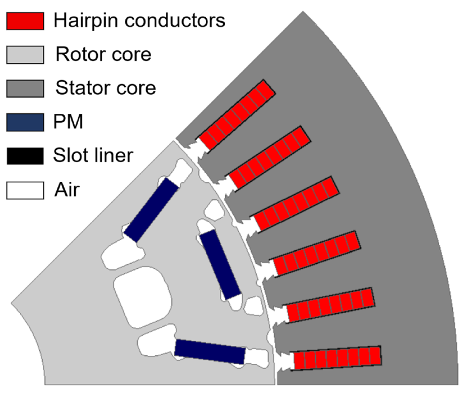
The machine taken as a reference in this study is a PM traction motor that is employed in medium-power hybrid electric vehicles [35]. The stator is provided with 48 slots and a distributed hairpin winding with eight rectangular conductors per slot and a coil pitch of five slots. The selected winding layout results in a high slot fill factor and is typical of modern automotive traction motors. The main specifications of the machine are summarized in Table 1, and the two-dimensional (2D) cross-sectional view of one pole pair is shown in Figure 1. The reference machine is the common platform for all investigated cooling topologies to ensure a fair comparison of thermal, electromagnetic, and hydraulic characteristics.

2.2. Cooling Topologies

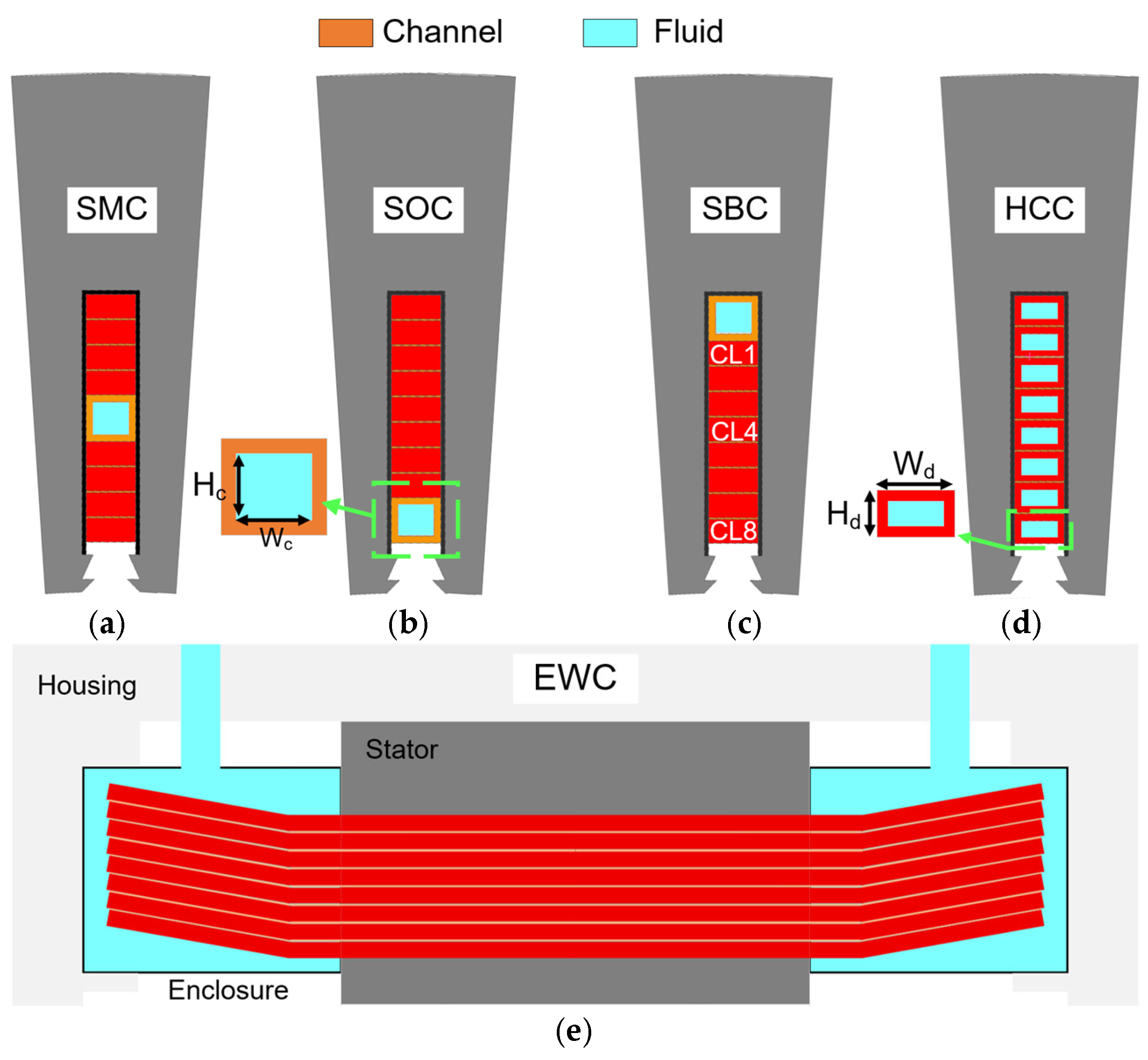
In order to achieve high continuous power capability under traction operating conditions, the reference PM machine in Figure 1 employs multiple cooling mechanisms targeting both stator and rotor thermal limitations. It is worth mentioning that all investigated cooling topologies employ the same hollow-shaft oil cooling system to ensure effective heat removal from the rotor assembly and PMs. Five winding cooling topologies are examined as shown in Figure 2. These configurations are different approaches to extracting heat from the winding region and are selected to evaluate the influence of the cooling-channel location and cooling strategy on the thermal and electromagnetic performance.
  • Slot-middle channel cooling (SMC): A cooling channel is placed between the layers 4 and 5 of the conductor and provides symmetric cooling around the winding area.
  • Slot-opening channel cooling (SOC): A cooling channel is placed adjacent to the slot opening, near the conductor layers closest to the air gap.
  • Slot-bottom channel cooling (SBC): A cooling channel is located near the slot bottom, next to the stator back iron.
  • Hollow conductor cooling (HCC): The coolant is circulated through internal channels in each conductor so that heat can be removed directly from the copper.
  • End-winding cooling (EWC): The cooling oil is directly fed to the end-winding region, and the slot conductors are indirectly cooled by thermal conduction.
Figure 2. Winding cooling topologies: (a) slot-middle channel cooling (SMC); (b) slot-opening channel cooling (SOC), (c) slot-bottom channel cooling (SBC); (d) hollow conductor cooling (HCC); (e) end-winding cooling (EWC).
Machines 14 00776 g002
The geometric and cooling parameters of the cooling topologies are summarized in Table 2. To have a fair comparison, the coolant flow rate is kept constant for all the cooling configurations during the study. Furthermore, identical conductor cross-sectional areas are considered for the cooling concepts that modify the slots (SOC, SMC, and SBC). Therefore, the differences in thermal, electromagnetic, and hydraulic performance observed can be mainly attributed to the cooling topology and channel location rather than to variations in copper volume or coolant supply conditions.

2.2.1. End-Winding Cooling (EWC)

The EWC configuration serves as a reference for direct end-winding cooling. In this arrangement, cooling oil is supplied from both sides of the machine and distributed over the end-winding region. Therefore, heat is removed directly from the winding overhangs, while the conductors inside the stator slot remain indirectly cooled through thermal conduction toward the end-winding and stator core. Since no cooling structure is introduced inside the slot, the original conductor dimensions are preserved. Each conductor layer (CL) has a width of 3.5 mm and a height of 2.1 mm, resulting in a conductor cross-sectional area of 7.35 mm2 and a slot fill factor of 69%. Although this arrangement preserves the highest copper utilization, the relatively long thermal path from the slot conductors to the coolant may result in elevated hotspot temperatures under high loading conditions.

2.2.2. Slot-Channel Cooling Topologies (SOC, SMC, and SBC)

In the stator slot, dedicated cooling channels are embedded, which provide more direct cooling to the slot region without changing the original slot dimensions. Consequently, some of the available slot area must be occupied for the cooling channel, thus reducing the conductors’ height from 2.1 mm to 1.7 mm. The conductor’s width is not changed and remains 3.5 mm, the conductor area is 5.95 mm2, and the slot fill factor is 55.86%. The effect of the cooling-channel location on heat extraction and temperature distribution within the slot area is investigated using three channel arrangements, namely SMC, SOC, and SBC, as illustrated in Figure 2. All three configurations use the same conductor dimensions, channel dimensions, and coolant flow rates. Thus, the difference in thermal or electromagnetic performance can be solely attributed to the position of the cooling channel. The coolant is electrically insulated from the winding conductors. A 50/50 water-ethylene glycol mixture is used as the coolant due to its superior thermal properties and low viscosity.

2.2.3. Hollow Conductor Cooling (HCC)

The HCC configuration utilizes the internal channels of each CL to directly circulate coolant. The external conductor dimensions are identical to the EWC design (3.5 mm × 2.1 mm), but each CL contains a concentric hollow region of 2 mm × 0.7 mm. The hollow dimensions are chosen in such a way that the remaining copper area is equal to that of the slot-channel cooling configurations. Consequently, for the same operating temperature, these configurations exhibit nearly identical DC resistance and DC copper losses. Therefore, the observed differences in thermal and electromagnetic performance can be primarily attributed to the cooling topology rather than variations in conductor cross-sectional area. In contrast to the slot-channel arrangements, the coolant is in direct contact with the conductor, which allows for a highly effective heat extraction from the main heat source. Therefore, automatic transmission fluid (ATF) oil is used as the coolant, which is electrically insulating. The coolant flows into the conductors from one end-winding side and flows axially through the slot conductors and out from the other side [36]. Several parallel flow paths are considered to improve the distribution of the coolant and to reduce the hydraulic pressure drop.
The thermophysical properties of the cooling fluids used in the present study are summarized in Table 3. Water has better heat-transfer characteristics than oil, but electrically insulating oil is used in EWC and HCC due to the fact that the coolant is in direct contact with energized conductors. In contrast, the slot-channel configurations use water-ethylene glycol because the coolant is electrically isolated from the winding.
The cooling topologies discussed above involve different trade-offs between thermal performance, copper fill factor, manufacturability, hydraulic penalty, and electromagnetic behavior. Slot cooling channels improve the heat extraction capability by decreasing the thermal path between winding and coolant but decrease the available copper area inside the slot. In addition, HCC allows for highly efficient direct conductor cooling. However, it alters the conductor geometry and adds additional hydraulic complexity. Hence, an electromagnetic–thermal coupled analysis framework is required to evaluate the overall effectiveness of each cooling topology under different operating conditions. It should be noted that the investigated cooling concepts belong to different categories of winding-cooling technologies and involve different implementation constraints. The slot-channel cooling topologies (SMC, SBC, and SOC) represent variations in indirect slot cooling, whereas EWC and HCC are direct winding-cooling approaches. Consequently, the manufacturing requirements, coolant management strategies, and integration challenges differ among these concepts. Nevertheless, all configurations are evaluated under identical machine dimensions, operating conditions, and thermal constraints in order to provide a comparative assessment of their achievable thermal and electromagnetic performance and to highlight the trade-offs associated with each cooling concept.

3. Multi-Physics Modeling Framework

The electromagnetic losses used as heat sources in the thermal model are obtained from a 2D time-stepping FEM electromagnetic analysis. The loss components include copper losses, stator core losses, rotor core losses, and PM loss. The winding resistance temperature dependence couples the thermal and electromagnetic behavior of electrical machines strongly. The electrical resistivity of the copper increases with increasing winding temperature, resulting in higher Joule losses and more heat generation. This dependence can be written as
ρ c u ( T ) = ρ c u , r e f [ 1 + α ( T T r e f ) ] ,
where ρcu is the copper resistivity at the working temperature of T, ρcu,ref is the resistivity at the reference temperature of Tref, and α is the temperature coefficient of copper resistance. Thus, an accurate prediction of the winding temperature distribution is important for the machine efficiency, thermal loading, and continuous operating capability assessment. Core losses are calculated using the Bertotti coefficients, in which the total iron loss is decomposed into hysteresis, classical eddy current, and excess loss. Moreover, the total winding losses are obtained directly from the FEM electromagnetic analysis and include both DC and AC copper loss components. The AC loss component accounts for the additional frequency-dependent losses caused by skin effect, proximity effect, and leakage-flux-induced eddy currents within the CLs. The DC copper losses are subsequently calculated from the CL resistance at the operating temperature using (1). The AC copper losses of individual CLs are then extracted by subtracting the calculated DC losses from the total FEM-predicted winding losses. Hence, the layer-resolved winding representation adopted in this work enables the AC and DC copper losses of individual CLs to be evaluated separately. The calculated losses are subsequently mapped into the thermal model and updated iteratively according to the temperature-dependent material properties until convergence is achieved.
Three-dimensional (3D) thermal FEM can provide highly accurate predictions of temperature distribution and heat-transfer mechanisms in electrical machines. However, their computational cost becomes prohibitive when multiple operating points, cooling configurations, or iterative magnetothermal calculations must be evaluated. Conversely, analytical thermal network models offer very fast computation times and have been widely used for hotspot prediction, real-time temperature estimation, and thermal monitoring of electrical machines [37,38]. Nevertheless, their accuracy strongly depends on the assumptions adopted for the thermal resistances and capacitances [39]. Therefore, to achieve a balance between computational efficiency and prediction accuracy, a hybrid thermal framework is employed in this work. A 2D thermal FEM is used to predict the temperature distribution within the active parts of the machine. A thermal framework according to [40,41] has been utilized to consider heat transfer in the end-space region.
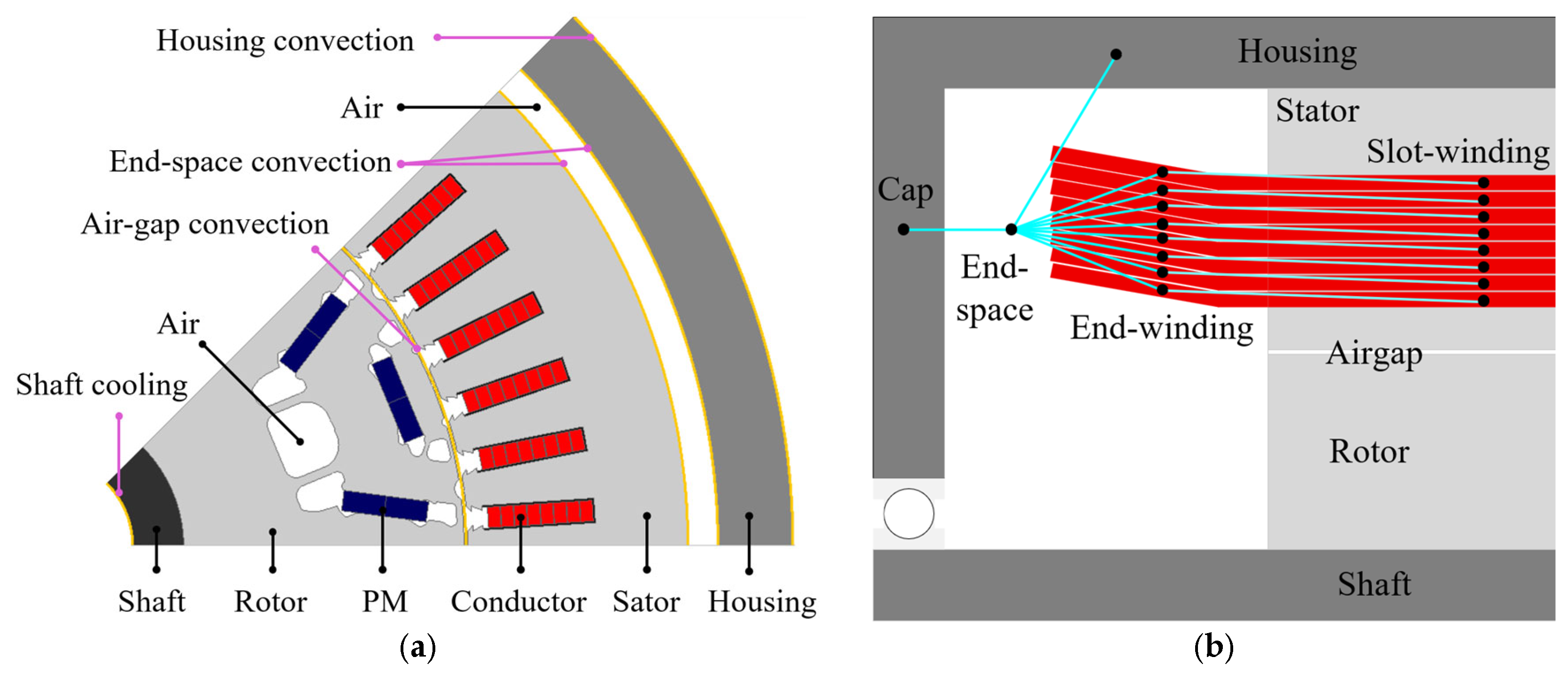
Figure 3 illustrates the thermal boundary conditions. The radial heat transfer within the active part of the machine is captured using a 2D FEM thermal model with the boundary conditions shown in Figure 3a. Since the 2D formulation cannot represent axial heat transfer in the end-winding region, an additional thermal network is introduced. As illustrated in Figure 3b, the end-winding exchanges heat through several parallel thermal paths.

3.1. Heat Transfer and Hydraulic Modeling

Since this work focuses on evaluating the influence of different winding cooling topologies, the rotor cooling arrangement remains identical across all configurations investigated. Therefore, all cooling concepts considered in this study employ the same hollow-shaft oil cooling system to provide consistent heat extraction from the rotor and PMs. Consequently, the thermal and electromagnetic differences observed among the investigated cases can be attributed solely to the winding cooling topology.

3.1.1. Hollow-Shaft Cooling

The hollow-shaft cooling system is designed to remove heat generated within the rotor assembly and to maintain the PM temperature within a safe operating margin during high-speed operation. Heat transfer between the coolant and the internal shaft surface is represented using an equivalent convective boundary condition. The corresponding heat transfer coefficient (HTC) is determined from a Nusselt-number-based correlation that accounts for both shaft rotation and internal oil flow. The rotational Reynolds number is calculated as [42].
R e θ = ρ a ω R s h 2 μ a ,
where ω is the rotor angular velocity, Rsh is the shaft radius, μa and ρa are the density and dynamic viscosity associated with the rotating fluid region, respectively. The Reynolds number associated with the fluid coolant flow through the shaft is given by:
R e f = ρ f V f D h μ f ,
where Vf is the average coolant velocity, Dh is the hydraulic diameter of the oil path, and μf and ρf are the density and dynamic viscosity of the coolant, respectively.
The average coolant velocity is determined from the coolant flow rate as the ratio of volumetric flow rate to cross-sectional flow area of the shaft nozzle ( V f = V ˙ f A f ). The heat transfer enhancement resulting from the combined effects of shaft rotation and oil circulation is represented through the Nusselt number:
N u s h = 8.826 × 10 12 R e θ 1.571 R e f 2.75 P r 0.4 ,
where Pr is the coolant Prandtl number, which is defined as P r = ( μ f c p / k f ) with cp representing specific heat capacity. Finally, the effective convective heat transfer coefficient applied at the shaft–coolant interface is obtained from
H T C s h = N u s h k f D h ,
where kf is the thermal conductivity of the coolant. This formulation enables the influence of both rotor speed and coolant flow rate on rotor heat extraction to be incorporated into the thermal model, providing a realistic representation of the rotor cooling performance throughout the operating range.

3.1.2. Slot Cooling Channels

The thermal performance of the cooling topologies depends strongly on the convective heat transfer between the coolant and the cooling channel surfaces. Therefore, the convective heat transfer coefficient and hydraulic pressure drop are calculated prior to the thermal finite element analysis and subsequently applied as boundary conditions in the thermal model.
The flow passages considered in this study have a rectangular cross-section. The hydraulic diameter for a rectangular area is first determined as
D h = 4 A c P c ,           A c = H c W c ,         P c = 2 ( H c + W c ) ,    
where Ac is the flow area and Pc is the perimeter of the cooling channel, and Hc and Wc are the channel height and width, respectively. Since the flow inside the cooling channels remains in the laminar regime, the heat transfer coefficient is determined using correlations for thermally developing laminar flow. The Graetz number is first calculated as
G z = R e f . P r D h L c ,
where Lc is the channel length. For the coolant employed in this study, the Nusselt number is evaluated from [43].
N u = ( μ b μ w ) 0.14 [ 3.66 + 0.0668 G z 1 + 0.04 G z 2 / 3 ] ,
where μb and μw denote the coolant viscosity at the bulk fluid temperature and wall temperature, respectively. The convective heat transfer coefficient is then obtained from (5) by replacement. The obtained HTC is applied as the convection boundary condition on the cooling channel walls in the thermal finite element model. In addition to the thermal analysis, the hydraulic losses associated with the coolant flow are evaluated. The aspect ratio of the rectangular channel is defined as β = m i n ( H c , W c ) m a x ( H c , W c ) . The Darcy friction factor for laminar flow in rectangular channels is calculated using [43].
f f = 96 R e f ( 1 1.355 β + 1.946 β 2 1.701 β 3 + 0.956 β 4 0.253 β 5 ) ,
The pressure drop along the cooling channel is subsequently determined using the Darcy–Weisbach equation.
P = f L c D h ρ f μ f 2 2 ,
Finally, the pumping power required to circulate the coolant through the channel is calculated as P p u m p = P V f ˙ .
The calculated hydraulic parameters for the investigated direct-cooling configurations are summarized in Table 4. It should be mentioned that as EWC does not employ dedicated internal cooling channels, the coolant is not subjected to the same confined flow conditions as in slot-channel cooling or HCC. Consequently, the pressure-drop analysis reported in Table 4 is limited to the cooling topologies that utilize internal flow passages.
As can be noticed, although the HCC enables direct heat extraction from the CLs, it introduces a substantially higher hydraulic resistance. The predicted pressure drop reaches approximately 11.685 kPa, compared with only 0.495 kPa for the slot-channel configurations. Consequently, the required pumping power increases from 0.04 W to 0.93 W. These hydraulic penalties are considered together with the thermal and electromagnetic performance in the comparative assessment presented in Section 4.

3.1.3. End-Winding Heat Transfer

The thermal behavior of the end-winding region is strongly influenced by the fluid surrounding the conductors. In the reference machine, where no oil is supplied to the end-winding region, the surrounding medium is assumed to be enclosed inside the machine housing. Under these conditions, the convective heat transfer coefficient is estimated using an empirical correlation relating the heat transfer coefficient to a characteristic fluid velocity within the end-space region [44].
H T C E W = k 1 ( 1 + k 2 v r e f k 3 ) ,
where vref is the characteristic fluid velocity in the end-space region, and k1, k2, and k3 are experimentally derived coefficients. These coefficients are typically determined for air-filled electrical machines and take into account the influence of rotor-induced airflow and localized fluid motion in the end-cap cavity.
The thermal behavior of the end-winding region is considerably different when oil is injected into the enclosure compared to the thermal behavior of an air-filled enclosure. The higher density, thermal conductivity, and heat capacity of the oil result in better heat extraction from the winding surfaces. Thus, HTC from (11) must be corrected to reflect the change in the cooling medium. In order to model this effect, a fluid-dependent scaling factor is used based on the thermophysical properties of the coolant. Assuming that forced convection dominates the heat transfer process in the end-space region, the scaling factor can be expressed as [45].
S F = ( k f k a ) ( ρ f / ρ a μ f / μ a ) 0.8 ( ( c p , f / c p , a ) ( μ f / μ a ) k f / k a ) 0.33 ,
where the subscript f refers to the cooling fluid used in the end-winding region. The effective end-winding heat transfer coefficient is then obtained as H T C E W , f = S F . H T C E W , a i r . It is worth mentioning that the investigated machine incorporates an end-region oil collector positioned between the stator end-winding and the rotor. Besides collecting and redirecting the cooling oil, this component acts as an aerodynamic barrier that largely isolates the end-winding cavity from the rotor airflow. Thus, HTCEW is only weakly dependent on the rotor speed and is mainly determined by the thermophysical properties of the surrounding medium. Furthermore, this design prevents the cooling oil from reaching the rotor surface, thereby mitigating windage effects and reducing parasitic mechanical losses during high-speed operation.

3.2. Experimental Validation

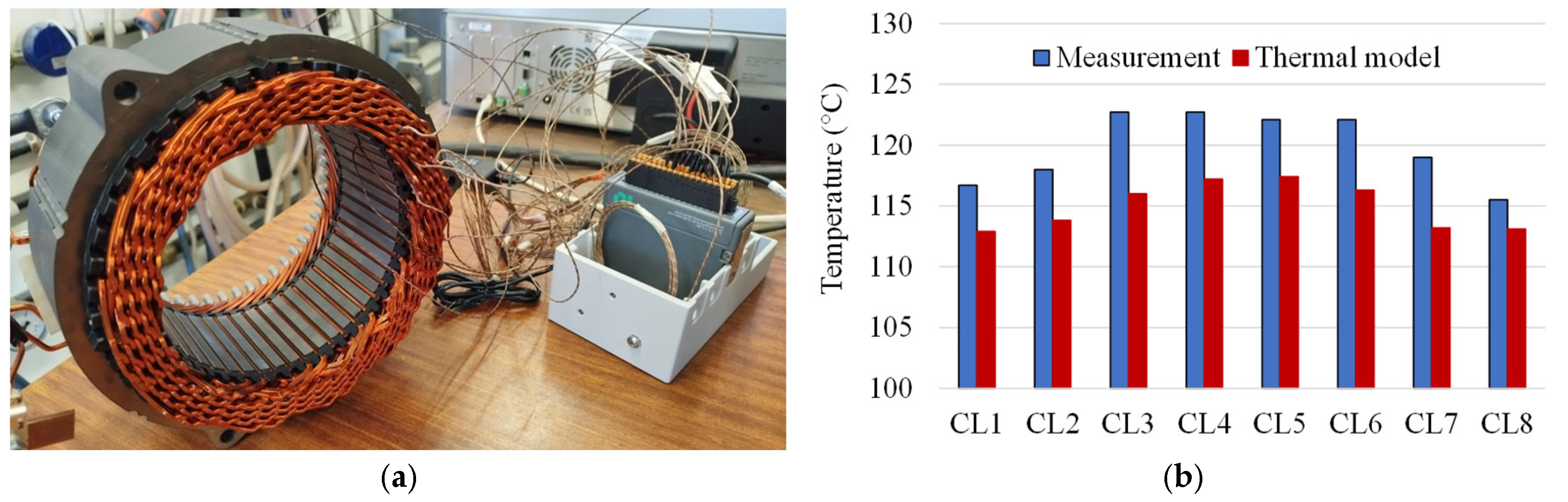
The thermal framework was experimentally validated in a hairpin stator with natural-air cooling at a current density of 5 A/mm2. Figure 4a shows that thermocouples were placed at different conductor layers to measure the temperature distribution along the slot. Comparison is shown in Figure 4b. Furthermore, the experimental and the numerical results show the same thermal trend with the highest temperatures in the intermediate conductor layers and the lowest temperatures near the slot boundaries. The maximum absolute temperature deviation is 6.6 °C, and the average absolute error is 5.2 °C with a mean relative error of 4.4% over all the CLs. This level of agreement is considered satisfactory for machine thermal analysis, considering the uncertainties related to material properties, thermal contact resistances, and convection boundary conditions. It is important to point out that the validation was performed with natural-air cooling, which is the most challenging case for the proposed framework because the thermal interaction between the slot-winding and end-winding regions becomes more significant without the direct liquid cooling. Thus, the obtained agreement provides confidence in the capability of the thermal model to predict the CL’s temperature under different cooling configurations.

4. Results and Discussion

This section presents the electromagnetic–thermal analysis of the investigated cooling topologies using the finite element framework described in the previous sections. The thermal simulations were supplied with loss distributions obtained from the electromagnetic model, while the convective boundary conditions were determined using the analytical heat-transfer and hydraulic models developed for each cooling configuration.
A particular challenge in hairpin winding is the strong interaction between thermal and electromagnetic phenomena. The high slot fill factor achieved by rectangular conductors reduces DC resistance and improves torque density; however, it also limits the available space for coolant integration. Furthermore, the large conductor dimensions promote skin and proximity effects, resulting in substantial AC copper losses at elevated electrical frequencies. Since copper resistivity increases with temperature, the winding losses themselves are temperature dependent. As a result, modifications introduced to improve cooling can simultaneously alter conductor geometry, current distribution, AC loss behavior, and overall machine efficiency. Therefore, a coupled multi-physics analysis is required to accurately evaluate the effectiveness of each cooling topology. The operating points investigated were selected to represent both low-speed and high-speed operating regions of the traction drive. At low speed, winding losses are dominated by DC components, and thermal performance is primarily influenced by conductor temperature. In contrast, at high speed, the electrical frequency increases substantially, resulting in strong skin and proximity effects that shift the loss generation toward the slot region. Consequently, the relative effectiveness of each cooling topology may vary depending on the operating condition.
The results are presented in several stages. First, the conductor temperature distribution and thermal gradients within the slot are analyzed to investigate the local cooling effectiveness of each topology. Subsequently, the loss components are examined to identify how the cooling arrangement influences the distribution of copper and electromagnetic losses. The relationship between AC and DC copper losses is then investigated to explain the thermal behavior observed at high-speed operation. Finally, the overall thermal performance, efficiency, loading capability, hydraulic requirements, and implementation complexity of the different cooling strategies are compared.
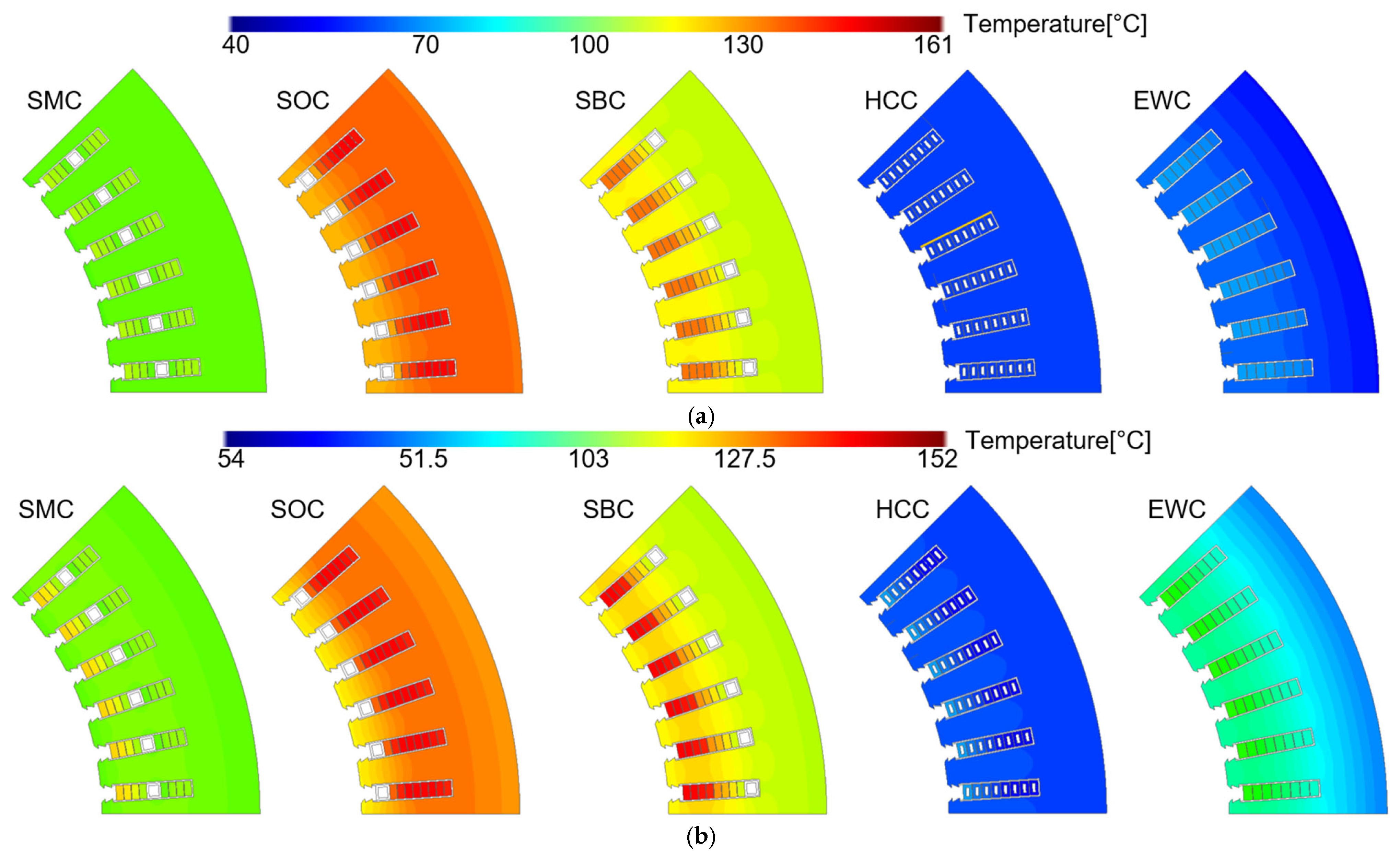
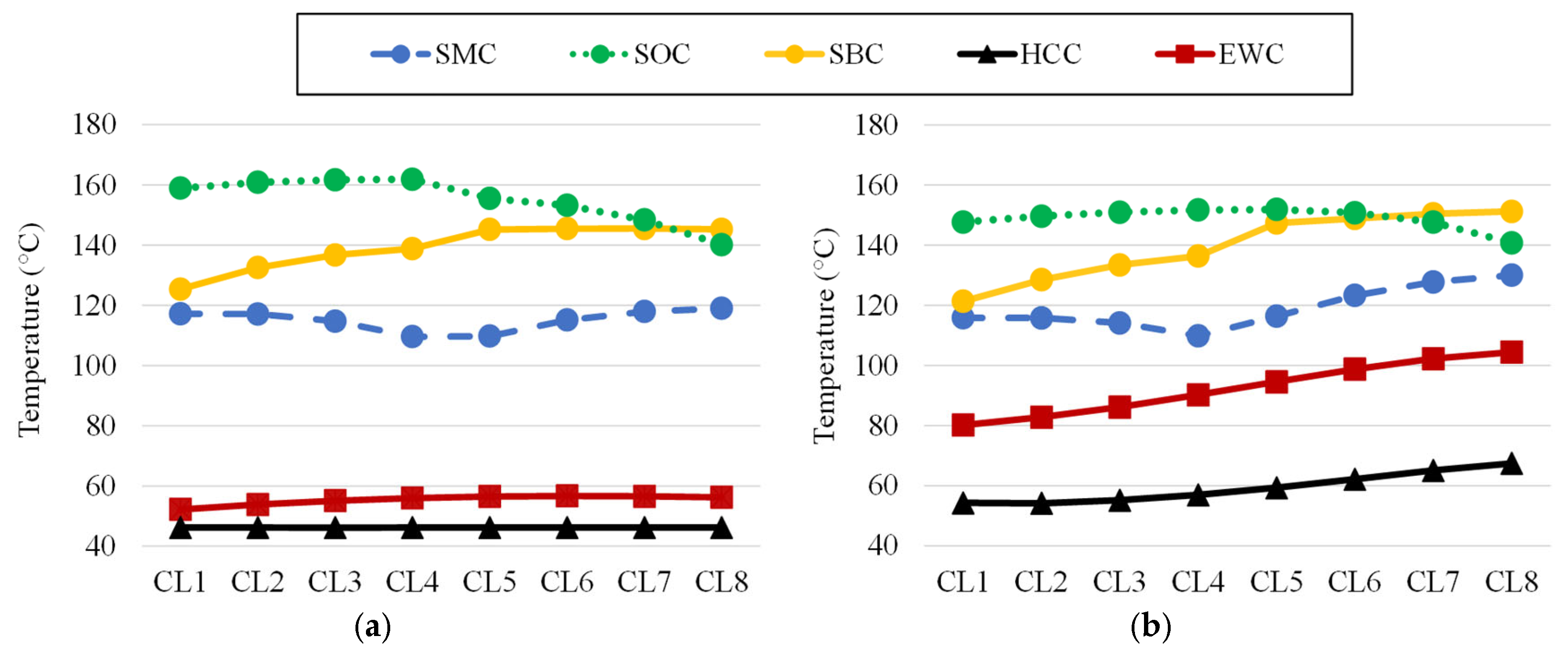
Figure 5 illustrates the temperature distribution across the eight CLs at low-speed (1500 rpm, 10.8 kW) and high-speed (17,000 rpm, 18.6 kW) operating points. The conductor layers are numbered from CL1 at the slot bottom to CL8 near the air-gap region. As can be noticed, the slot-channel-based cooling configurations exhibit considerably higher temperatures than the direct cooling approaches. As shown in Figure 6a, SMC achieves the lowest hotspot temperature among the slot-channel cooling topologies, with a maximum conductor temperature of approximately 118 °C. By comparison, SBC and SOC are at hotspot temperatures of ~145 °C and ~162 °C, respectively. Therefore, moving the cooling channel from the slot opening to the thermal center of the slot results in an almost 27% reduction in the hotspot temperature. This enhancement can be attributed directly to the heat-transfer path in the CLs. In SMC, the coolant is located at the center of the slot area, which enables a more uniform removal of heat from both upper and lower CLs. In contrast, in SBC, the heat generated in the upper layers (CL5 to CL8) must pass through several CLs before reaching the coolant channel that is located at the bottom of the slot. SOC has a similar limitation, but with the direction of heat flow reversed. In this case, the CLs closest to the slot opening are directly cooled, while the lower CLs are thermally constrained due to the longer conduction path. As a result, the maximum hotspot temperature and the maximum temperature difference across the slot are obtained in the SOC. Moreover, EWC and HCC show substantially better thermal performance. The hotspot temperature is reduced to about 55 °C and 46 °C, which is roughly a 66% and 72% reduction compared to SOC, respectively. The most important reason for such a significant enhancement is the decrease in the thermal resistance between the heat source and the coolant. Specifically, HCC provides direct heat removal from each conductor through the internal cooling passages, resulting in the shortest thermal path and lowest thermal resistance between the CLs and the coolant.
Further thermal behavior can be observed for the high-speed operating point (Figure 6b). The hotspot location shifts to the CLs near the air gap, specifically CL7 and CL8. The trend is strongly associated with the increasing AC copper losses at higher electrical frequencies. Consequently, the CLs close to the slot opening are subjected to a stronger leakage flux, resulting in higher local loss densities and temperature increases. This phenomenon is especially observed in the EWC and HCC configurations, where the temperature gradient between CL1 and CL8 is about 25 °C and 14 °C, respectively. Nevertheless, while the losses are more localized to the upper CLs, HCC still offers the most uniform temperature distribution among all the cooling topologies. The relatively small temperature gradient across the CL demonstrates the effectiveness of the direct conductor cooling to suppress the thermal accumulation within the slot. In contrast, considerable thermal non-uniformity is maintained in the slot-channel cooling arrangements, given that the heat generated in the conductors must first move through the nearby conductors, insulation layers, and impregnation materials before it can reach the coolant. Therefore, although the thermal gradients increase at high speed due to concentration of the AC loss, direct cooling of the conductor still shows its benefits in terms of temperature uniformity and hotspot reduction.
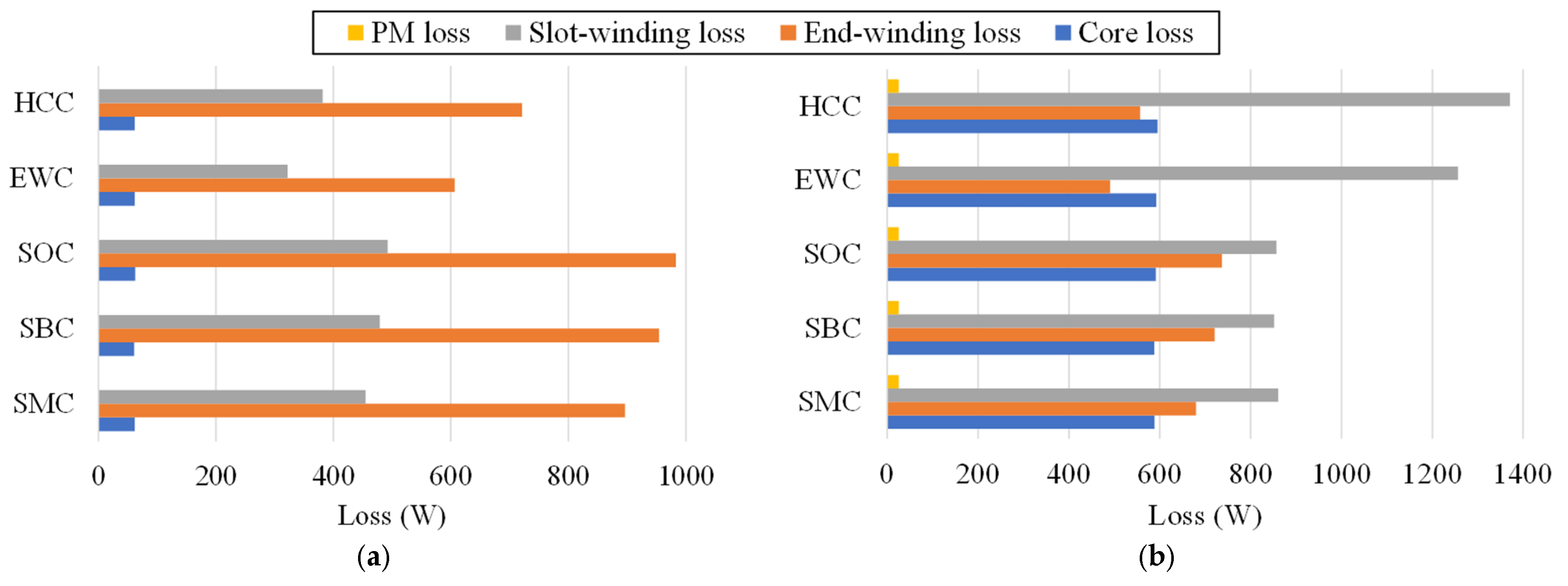
To further investigate the origin of the temperature distributions observed in Figure 6, Figure 7 presents the breakdown of losses into core, slot-winding, end-winding, and PM losses. From Figure 7a, end-winding losses are the highest portion of total copper losses in all cooling schemes. This behavior is expected because the investigated machine has a relatively short active stack length, causing the end-winding resistance to represent a significant portion of the total phase resistance. In the reference machine, the slot-winding resistance accounts for only approximately 34% of the total phase resistance, indicating that a substantial fraction of the copper losses is generated in the end-winding region. The DC copper losses are much higher than other loss sources because the resistance of copper increases approximately linearly with temperature. This creates a positive thermal feedback mechanism in which increased losses generate additional heat, further increasing winding resistance. The thermal benefit of EWC is immediately visible. By directly cooling the end-winding region, the corresponding copper losses decrease by approximately 32% relative to SMC. In addition, HCC further reduces the total winding temperature, producing the lowest total loss among all cooling configurations. The lowest losses are observed for HCC and EWC because their superior cooling capability reduces conductor temperature and therefore decreases copper resistivity. It should be noted that despite the lower operating temperature of HCC, the resistance reduction caused by cooling cannot completely compensate for the loss of copper area. As a result, HCC exhibits higher DC copper losses than EWC under the same current loading.
At 17,000 rpm, the loss distribution changes considerably. Figure 7b shows that the slot-winding losses become the dominant loss component, exceeding end-winding losses in all investigated cooling schemes. The slot-winding loss increases from approximately 320–490 W at low speed to nearly 850–1370 W at high speed. For HCC, slot-winding losses exceed 1370 W, which is approximately 59% higher than SMC. This transition is caused by the rapid increase in AC copper loss associated with skin and proximity effects at high electrical frequencies. Interestingly, HCC and EWC exhibit the largest slot losses despite having the lowest temperatures. This initially counterintuitive behavior highlights the strong coupling between electromagnetic and thermal physics in hairpin windings. These results demonstrate that thermal improvements do not necessarily lead to lower total winding losses at high speed. It is worth mentioning that although the HCC configuration exhibits the highest copper losses at high-speed operation, it maintains the lowest hotspot temperature. This is because of its significantly lower thermal resistance and approximately five times higher effective heat dissipation capability compared with the slot-cooling topologies. By removing heat directly from each conductor, the increase in heat generation is negligible rather than the enhanced heat extraction, resulting in a superior thermal performance.
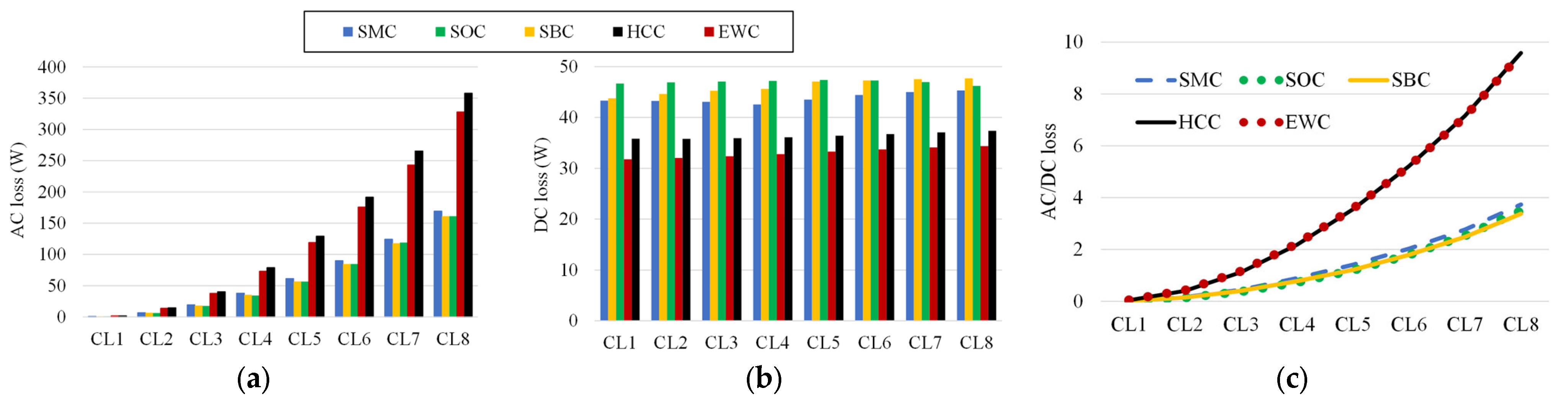
Figure 8 explains the electromagnetic origin of the thermal behavior observed at high speed. A notable difference can be observed in Figure 8a between AC loss of the cooling schemes. HCC and EWC exhibit higher AC losses than SMC, SBC, and SOC. This behavior is related to the lower operating temperatures achieved by HCC and EWC, which reduce copper resistivity. According to:
δ = 2 ρ ω μ   ,
where δ is the skin depth, ρ is the electrical resistivity, ω is the angular frequency, and μ is the magnetic permeability, a reduction in resistivity decreases the skin depth and intensifies current crowding within the conductor cross-section. As a result, AC losses become more pronounced. Moreover, the AC copper losses increased significantly from CL1 to CL8 for all cooling topologies, indicating the strong influence of leakage flux near the slot opening. Consequently, the conductors closest to the air gap experience the highest AC losses due to skin and proximity effects. For example, in HCC, the AC loss increases from only a few watts in CL1 to more than 350 W in CL8. Nevertheless, despite the higher AC losses, HCC maintains the lowest CLs temperature due to the direct removal of heat from each conductor through the internal cooling passages.
The opposite trend is observed for DC losses, as exhibited in Figure 8b. HCC and EWC maintain conductor temperatures approximately 60 °C to 100 °C lower than the slot-channel solutions, reducing DC resistance and therefore decreasing the DC copper losses by approximately 20% to 30%. This trade-off becomes evident in Figure 8c, where the AC-to-DC loss ratio increases significantly in the CLs toward the air-gap side. For SMC, SBC, and SOC, the ratio in CL8 remains below 4. In contrast, the ratio approaches 10 for HCC and EWC, indicating that AC losses become the dominant contributor to winding losses. The conductor dimensions also influence this behavior, in addition to the temperature effect. The AC loss generated by skin and proximity effects can be approximately related to the conductor thickness as follows [46]:
P A C B 2 f 2 H d 2 6 ρ ,
where PAC is the AC copper loss, B is the local magnetic flux density, f is the electrical frequency, and Hd is the characteristic conductor dimension perpendicular to the flux penetration direction, which is the height of the conductor. Since the slot-cooling configurations require a reduction in conductor height from 2.1 mm to 1.7 mm to accommodate the cooling channels, the effective eddy-current path becomes shorter, resulting in lower AC losses. Finally, the elevated conductor temperatures also lead to higher DC copper losses, which further reduces the AC-to-DC loss ratio. Therefore, the lower AC loss sensitivity of the slot-cooling topologies can be attributed to a combined effect of reduced conductor dimensions, increased skin depth, and larger DC copper losses.
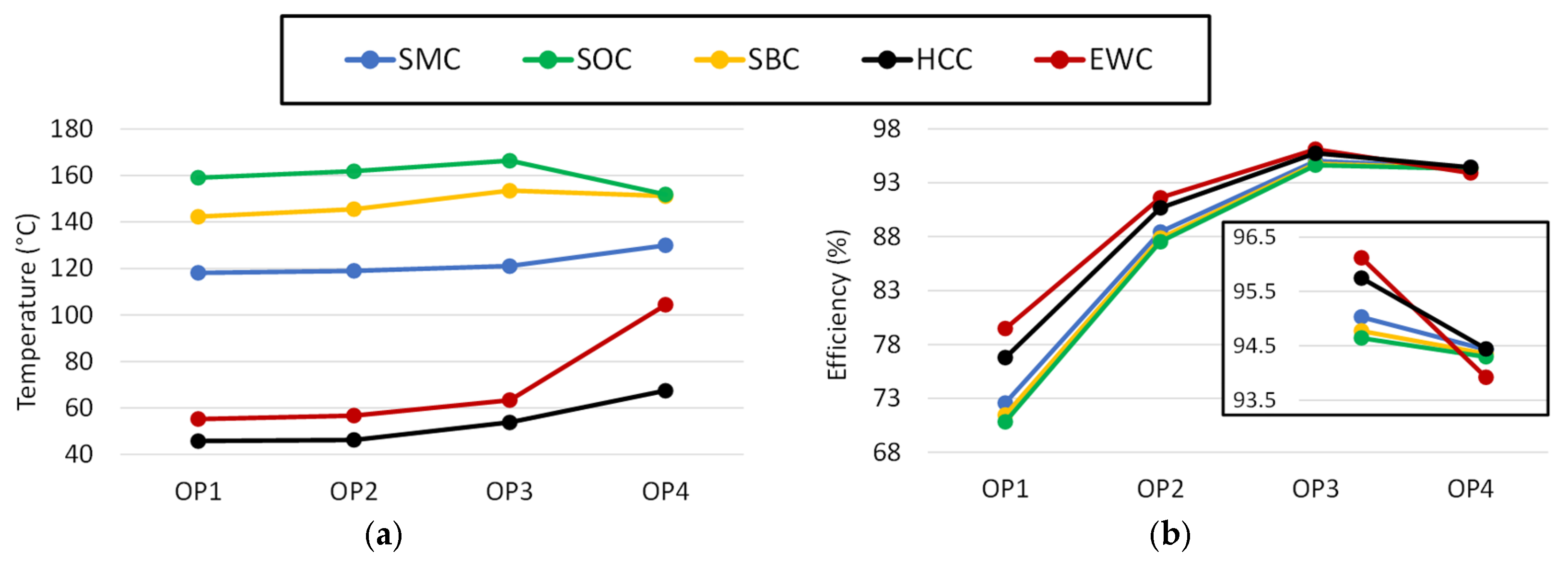
Figure 9 compares the hotspot temperature in the slot area and the efficiency of cooling topologies at four representative operating points listed in Table 5. Evaluating both metrics is important because the hotspot temperature determines the thermal limit and continuous loading capability of the machine, whereas efficiency reflects the overall impact of the cooling strategy on machine losses and energy conversion performance.
As shown in Figure 9a, HCC and EWC consistently achieve the lowest hotspot temperatures throughout the operating range. At the base-speed operating point (OP3), the hotspot temperature decreases from approximately 166 °C for SOC and 153 °C for SBC to only 63 °C and 54 °C for EWC and HCC, respectively, corresponding to a reduction of nearly 65% compared with SOC. Among the slot-channel cooling topologies, SMC consistently exhibits the lowest hotspot temperature, confirming that placing the cooling channel near the thermal center of the slot provides the most effective heat extraction path. It is worth mentioning that the relatively low hotspot temperatures predicted for the EWC and HCC configurations are consistent with the moderate current densities considered in this study (13.6–16.8 A/mm2) and a coolant inlet temperature of 40 °C. For comparison, [47] reported a hotspot temperature of 176 °C for a HCC system operating at a substantially higher current density of 59.7 A/mm2 and a coolant inlet temperature of 60 °C.
The efficiency comparison demonstrated in Figure 9b follows the loss trends. At low- and medium-speed operating points (OP1–OP3), EWC and HCC achieve the highest efficiencies, reaching approximately 96.1% and 95.7% at OP3, respectively, compared with 94.6% for SOC. Although the efficiency difference is less than 2%, such an improvement corresponds to a substantial reduction in heat generation in high-power traction applications. As the operating point moves into high-speed (OP4), the efficiency difference between the cooling topologies becomes noticeably smaller. While HCC maintains the highest efficiency at approximately 96%, SMC, SBC, and SOC achieve efficiencies between 95.45% and 95.48%, differing by less than 0.6% from HCC. This observation suggests that, despite their higher winding temperatures, the slot-channel cooling topologies remain competitive in the field-weakening region where AC losses become increasingly dominant.
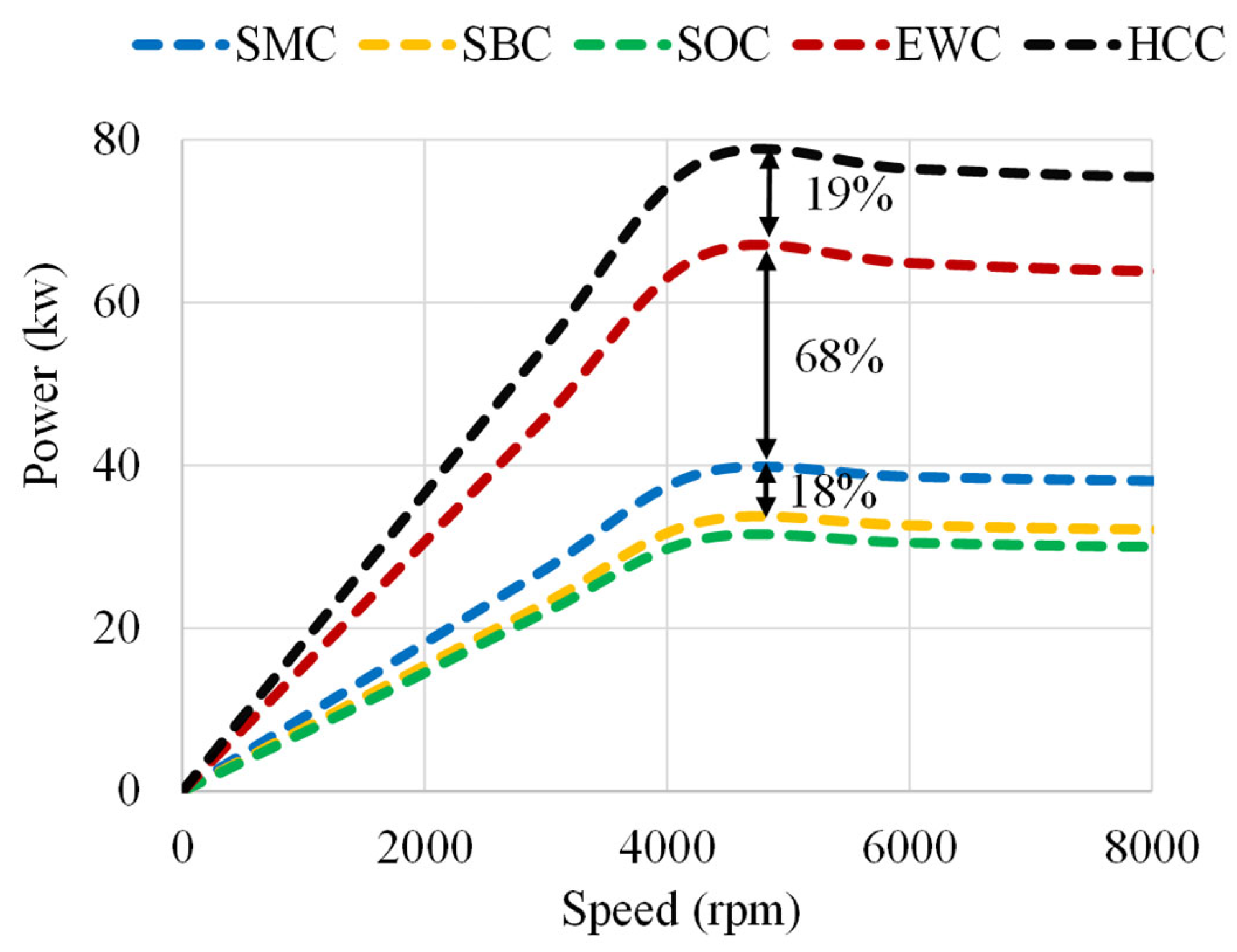
Although the investigated cooling concepts belong to different cooling categories and involve different implementation constraints, they are compared here under identical machine dimensions, operating conditions, and thermal limits to quantify the achievable performance trade-offs associated with each cooling strategy. Figure 10 quantifies how the available thermal margin can be translated into increased continuous power without exceeding the allowable winding temperature limits. A maximum winding hotspot temperature of 165 °C was adopted as the thermal constraint for the continuous power-speed capability analysis, corresponding to the thermal limit of a Class H insulation system. Among the slot-channel cooling configurations, SMC achieves higher loading capability, reaching approximately 39 kW compared with 31 kW for SOC and 33 kW for SBC. Compared to SOC, this value corresponds to an improvement of nearly 26%, highlighting the importance of cooling-channel placement within the slot. Since all three topologies employ identical channel dimensions, coolant flow rates, and machine geometry, the observed improvement can be attributed solely to the more favorable thermal location of the cooling channel in SMC. A substantially higher power density is obtained with direct cooling approaches. EWC extends the continuous power capability to approximately 67 kW, representing an improvement of nearly 68% over SMC and more than a twofold increase compared with SOC. EWC directly targets this thermal bottleneck and thereby significantly increases the permissible continuous current loading. HCC achieves the highest continuous power capability, approximately 79 kW. This corresponds to improvements of approximately 100% and 155%, respectively, over SMC and SOC. The increase from EWC to HCC is relatively slight, about 19%, though it indicates the benefit of removing heat directly from the conductors instead of relying on conduction through the winding structure. These results show that thermal management directly influences the achievable continuous operating envelope of hairpin traction machines.
The studied cooling topologies are compared with respect to thermal performance, efficiency, loading capability, hydraulic requirements, and implementation complexity in Table 6. The results highlight the fundamental trade-offs of each cooling approach and indicate that the ideal solution relies greatly on the intended application.
HCC exhibits optimal loading capability and the lowest hotspot temperatures across all the examined topologies, which is consistent with the thermal and power-speed data reported. HCC removes heat directly from the conductors, permits the maximum continuous current density, and extends the continuous operating envelope to ~79 kW. In addition, HCC offers the maximum efficiency at high-speed operation due to its thermal management. Nevertheless, this advantage comes at the cost of much increased hydraulic demand. The pressure drop of the HCC system was roughly 23 times greater than that of the slot-channel arrangements, increasing the pumping power from 0.04 W to 0.93 W. In addition, HCC requires unique manufacturing techniques, reliable sealing, and homogenous coolant distribution in the winding, which adds to the complexity and cost of the production. EWC is a particularly attractive compromise between performance and practicality. Its loading capacity is roughly 19% lower than HCC but still provides a 68% increase compared to SMC, with great thermal performance and comparatively minimal implementation complexity. EWC reduces production challenges of HCC and efficiently addresses the primary thermal bottleneck of short-stack hairpin machines, as the cooling circuit is localized to the end-winding region. Among the various slot-channel cooling topologies, the SMC topology demonstrates the best overall performance. The cooling channel location at the thermal center of the slot reduces the average heat-transfer path between the conductors and the coolant. This leads to lower hotspot temperatures and higher loading capabilities than SBC and SOC. Moreover, all slot-channel topologies have very low hydraulic requirements and can be realized with ordinary manufacturing procedures, making them desirable choices for applications with low-cost and moderate-power-density requirements. The hydraulic requirement ratings reported in Table 6 are based not only on the pressure-drop characteristics presented in Table 4, but also on the overall complexity of the coolant circulation system. Although EWC does not employ confined flow passages and therefore was not included in the pressure-drop analysis, it requires oil supply, collection, recirculation, filtration, and heat-exchanger integration within the drivetrain cooling system. Consequently, EWC is classified as having a moderate hydraulic requirement despite its relatively low hydraulic losses. In contrast, the slot-channel topologies combine very low pressure-drop penalties with relatively simple coolant delivery systems, resulting in a low hydraulic requirement rating.
It is worth noting that the incremental value of each cooling enhancement is progressively diminished as the primary thermal bottlenecks are addressed. The primary performance improvement comes from the shift from slot-channel cooling to EWC, with the additional increase from HCC being moderate. Therefore, SMC solutions are most appropriate for intermediate power density machines, EWC is the optimum balance between performance and implementation complexity, and HCC is attractive only when the highest continuous power density is the primary design target.

5. Conclusions

This paper presented a multi-physics comparison of various winding cooling topologies for a high-power-density PM machine with hairpin windings. A coupled electromagnetic–thermal framework based on FEM and a thermal model is used to evaluate the interaction between the cooling topology, the copper losses, the efficiency, the loading capability, and the hydraulic requirements. The main results of this work can be summarized as follows:
  • The location of the cooling channel significantly influences the thermal behavior of slot-cooled hairpin windings. Among the slot-channel arrangements investigated, SMC consistently achieved the lowest hotspot temperatures due to its symmetric cooling position near the thermal center of the winding region. Compared with SOC, SMC reduced the hotspot temperature by approximately 27% at the investigated operating conditions.
  • Direct cooling approaches substantially outperformed slot-channel cooling configurations. At the base-speed operating point, the hotspot temperature was reduced from approximately 166 °C in SOC to 63 °C and 54 °C in EWC and HCC, respectively, corresponding to temperature reductions by 60%. This means that by using EWC or HCC, the current density can be increased and hence the amount of PM can be reduced for a fixed output power compared to, e.g., SOC.
  • The dominant loss mechanism strongly depends on the operating condition. At low speed, end-winding copper losses represented the largest fraction of the total winding loss due to the short active stack length. At high speed, AC copper losses became dominant and shifted the loss concentration toward the CLs located near the air-gap region.
  • Improved cooling does not necessarily result in lower high-speed copper losses. The lower conductor temperatures achieved by EWC and HCC reduce copper resistivity, thereby decreasing skin depth and increasing current crowding effects. Consequently, these cooling schemes exhibited higher AC copper losses despite maintaining substantially lower temperatures.
  • The slot-cooling topologies were less sensitive to AC loss than EWC and HCC due to the combination of higher resistivity of the conductor, lower height of the conductor, and lower path length of eddy currents. This indicates a strong coupling between the cooling topology, the conductor geometry, and the electromagnetic performance.
  • Cooling topology directly determines the achievable continuous operating capability. The maximum continuous power increased from approximately 31 kW for SOC to 39 kW for SMC, 67 kW for EWC, and 79 kW for HCC. Therefore, direct cooling enables a substantial increase in the machine’s operating envelope. In other words, HCC can lead to a reduction in the PM amount for similar output power as, e.g., SOC.
  • Although HCC delivered the highest loading capability and the lowest hotspot temperatures, it also imposed the largest hydraulic and manufacturing penalties. The pressure drop increased from approximately 0.5 kPa for the slot-channel configurations to 11.7 kPa for HCC, resulting in a pumping power requirement approximately 23 times higher.
  • The results reveal a strong coupling between cooling topology, conductor temperature, and electromagnetic loss mechanisms. Improved cooling decreases the DC copper losses by reducing the temperature of the conductor but can also contribute to an increase in the AC copper losses because of the decreased resistivity and higher current crowding effects. The thermal and electromagnetic design of high-speed hairpin windings cannot be optimized separately and needs to be addressed by a coupled multi-physics approach.
Overall, the findings of this paper demonstrate that the selection of a winding cooling topology should be based on a multi-physics assessment rather than thermal performance alone. SMC provides the most balanced solution among slot-cooling configurations in moderate power-density applications. EWC offers an attractive compromise between thermal performance, loading capacity, manufacturability, and hydraulic complexity for high performance traction machines. HCC provides the highest possible performance, thereby rendering it the most appropriate choice for applications where the highest possible continuous power density is the primary design objective and the manufacturing complexity can be justified. Future work will focus on experimental validation of the proposed liquid-cooling topologies and the investigation of coupled thermo-mechanical effects associated with advanced hairpin cooling concepts.

Author Contributions

Conceptualization, A.Z., M.N.I. and P.S.; methodology, A.Z., M.N.I. and P.S.; software, A.Z.; formal analysis, A.Z., M.N.I. and P.S.; investigation, A.Z., M.N.I. and P.S.; resources, A.Z., M.N.I. and P.S.; data curation, A.Z.; writing—original draft preparation, A.Z.; writing—review and editing, M.N.I. and P.S.; visualization, M.N.I. and P.S.; supervision, P.S.; project administration, M.N.I.; funding acquisition, M.N.I. and P.S. All authors have read and agreed to the published version of the manuscript.

Funding

This research is financially supported by the Research Foundation—Flanders (FWO) under the project (G0A2824N) entitled “Computational efficient Multiphysics-based topology design of high-performance electric machines employing additive manufacturing”.

Data Availability Statement

The original contributions presented in this study are included in the article; further inquiries can be directed to the corresponding authors.

Conflicts of Interest

The authors declare no conflicts of interest.

References

  1. Guo, Y.; Liu, L.; Ba, X.; Lu, H.; Lei, G.; Yin, W.; Zhu, J. Designing high-power-density electric motors for electric vehicles with advanced magnetic materials. World Electr. Veh. J. 2023, 14, 114. [Google Scholar] [CrossRef] [Scilit]
  2. Jia, S.; Xu, Y.; Lin, J.; Liang, D.; Qu, R.; Liu, J. Overview of High Power Density Machines. CES Trans. Electr. Mach. Syst. 2025, 9, 390–406. [Google Scholar] [CrossRef] [Scilit]
  3. Wu, S.; Zhou, J.; Zhang, X.; Yu, J. Design and research on high power density motor of integrated motor drive system for electric vehicles. Energies 2022, 15, 3542. [Google Scholar] [CrossRef] [Scilit]
  4. Li, L.; Dai, L.; Niu, S.; Fu, W.; Chau, K. Critical review of direct-drive in-wheel motors in electric vehicles. Energies 2025, 18, 1521. [Google Scholar] [CrossRef] [Scilit]
  5. Zarghani, A.; Sergeant, P.; Ibrahim, M.N. Comprehensive Overview of Using Additive Manufacturing for Multiphysics Performance Improvement of Electric Machines. In Proceedings of the 2025 IEEE International Electric Machines & Drives Conference (IEMDC), Houston, TX, USA, 18–21 May 2025; pp. 141–147. [Google Scholar]
  6. Karakatsanis, T.S. Optimization and Performance Evaluation of PM Motor and Induction Motor for Marine Propulsion Systems. Appl. Syst. Innov. 2025, 8, 58. [Google Scholar] [CrossRef] [Scilit]
  7. Deisenroth, D.C.; Ohadi, M. Thermal Management of High-Power Density Electric Motors for Electrification of Aviation and Beyond. Energies 2019, 12, 3594. [Google Scholar] [CrossRef] [Scilit]
  8. Ghaheri, A.; Zarghani, A.; Afjei, E.; Torkaman, H. A Detailed Thermal Analysis for Performance Improvement of Axial Transverse-Flux-Switching PM Wind Turbine Generator. CES Trans. Electr. Mach. Syst. 2025, 9, 212–223. [Google Scholar] [CrossRef] [Scilit]
  9. Selema, A.; Ibrahim, M.N.; Sergeant, P. Electrical machines winding technology: Latest advancements for transportation Electrification. Machines 2022, 10, 563. [Google Scholar] [CrossRef] [Scilit]
  10. Shams Ghahfarokhi, P.; Podgornovs, A.; Cardoso, A.J.M.; Kallaste, A.; Belahcen, A.; Vaimann, T. Hairpin windings for electric vehicle motors: Modeling and investigation of AC loss-mitigating approaches. Machines 2022, 10, 1029. [Google Scholar] [CrossRef] [Scilit]
  11. Notari, R.; Nuzzo, S.; Savi, F.; Defanti, S.; Barater, D. An asymmetrical additively manufactured hairpin winding for increased efficiency and sustainability. IEEE Trans. Transp. Electrif. 2024, 10, 9529–9538. [Google Scholar] [CrossRef] [Scilit]
  12. Jiang, J.; Zou, T.; La Rocca, S.; Huang, H.; Ren, X.; La Rocca, A.; Prystupa, D.; Chen, D.; Gerada, D.; Zhu, S. Comparative Study of Stranded and Hairpin Windings for 250 kW Continuous Operation of High-Speed Heavy-Duty EV Traction Motor. IEEE Trans. Ind. Appl. 2025, 61, 9254–9268. [Google Scholar] [CrossRef] [Scilit]
  13. Tesfamikael, H.H.; Darmani, M.A.; Murataliyev, M.; Hague, R.J.M.; Gerada, C.; Degano, M. Loss Characterisation of Additively Manufactured Windings for Aerospace Propulsion Motors. IEEE Trans. Transp. Electrif. 2026. [Google Scholar] [CrossRef] [Scilit]
  14. Ahmad, Z.; Kallaste, A.; Naseer, M.U.; Vaimann, T.; Hussain, S. An Approach Towards AC Power Loss Reduction in Additively Manufactured Winding for Electrical Machine. IEEE Trans. Magn. 2026. [Google Scholar] [CrossRef] [Scilit]
  15. Ismaeel, S.M.; Ibrahim, M.N.; Rashad, E.M.; Sergeant, P. Asymmetric Hairpin Winding Design for Losses Reduction with Thermal Analysis for an Electric Vehicle Case Study. Energies 2024, 17, 6494. [Google Scholar] [CrossRef] [Scilit]
  16. Liang, P.; Chai, F.; Shen, K.; Liu, W. Water jacket and slot optimization of a water-cooling permanent magnet synchronous in-wheel motor. IEEE Trans. Ind. Appl. 2021, 57, 2431–2439. [Google Scholar] [CrossRef] [Scilit]
  17. Li, M.; Ma, C.; Zeng, S.; Hu, J.; Liu, J.; Wang, S. Cooling water jacket design of motorized spindle system using multi-objective topology optimization. Appl. Therm. Eng. 2023, 224, 120112. [Google Scholar] [CrossRef] [Scilit]
  18. Acquaviva, A.; Skoog, S.; Thiringer, T. Design and verification of in-slot oil-cooled tooth coil winding PM machine for traction application. IEEE Trans. Ind. Electron. 2020, 68, 3719–3727. [Google Scholar] [CrossRef] [Scilit]
  19. Park, J.; An, J.; Han, K.; Choi, H.-S.; Park, I.S. Enhancement of cooling performance in traction motor of electric vehicle using direct slot cooling method. Appl. Therm. Eng. 2022, 217, 119082. [Google Scholar] [CrossRef] [Scilit]
  20. Tikadar, A.; Joshi, Y.; Kumar, S. Comparative performance analysis of slot-embedded cooling of electric motors for various topologies. Appl. Therm. Eng. 2025, 268, 125843. [Google Scholar] [CrossRef] [Scilit]
  21. Liu, Y.; Cao, J.; Song, Y.; Chen, B.; Chen, B.; Li, L. Immersion evaporative cooling for high-power density motors in future aircraft. Appl. Therm. Eng. 2025, 278, 127036. [Google Scholar] [CrossRef] [Scilit]
  22. Reinap, A.; Andersson, M.; Márquez-Fernández, F.J.; Abrahamsson, P.; Alaküla, M. Performance estimation of a traction machine with direct cooled hairpin winding. In Proceedings of the 2019 IEEE Transportation Electrification Conference and Expo (ITEC), Detroit, MI, USA, 19–21 June 2019; pp. 1–6. [Google Scholar]
  23. Canseven, H.T. Advanced Direct Cooling Arrangements for Machines With Hairpin Windings. IEEE Access 2025, 13, 201711–201725. [Google Scholar] [CrossRef] [Scilit]
  24. Cai, W.; Li, G.; Yang, Y.; Gong, H. New Cooling Structure for Improving the Oil Cooling Effects of the End Winding of Flat Winding. In Proceedings of the Annual Conference of China Electrotechnical Society, Xi’an, China, 20–22 September 2024; pp. 578–587. [Google Scholar]
  25. Gai, Y.; Soulard, J.; Ma, X.; McMahon, R. Numerical and experimental investigation of fluid flow and heat transfer in hairpin end winding for an oil-injected cooled traction motor. IEEE Trans. Transp. Electrif. 2025, 11, 7243–7251. [Google Scholar] [CrossRef] [Scilit]
  26. Keuter, R.J.; Niebuhr, F.; Nozinski, M.; Krüger, E.; Kabelac, S.; Ponick, B. Design of a direct-liquid-cooled motor and operation strategy for the cooling system. Energies 2023, 16, 5319. [Google Scholar] [CrossRef] [Scilit]
  27. Kampker, A.; Brans, F.; Heimes, H.H.; Backes, T.; Dorn, B.; Al-Kinani, R. Parameter Study on Bending of Rectangular Copper Hollow Wire for the Use in Hairpin Stator Electric Traction Motors. In Proceedings of the 2023 13th International Electric Drives Production Conference (EDPC), Regensburg, Germany, 29–30 November 2023; pp. 1–7. [Google Scholar]
  28. Zharkov, E.; Shayhlislamov, A.; Okhotnikov, M. Stator winding design for a high specific power aircraft propulsion motor. Electr. Eng. 2026, 108, 123. [Google Scholar] [CrossRef] [Scilit]
  29. Venturini, G.; Volpe, G.; Popescu, M. Slot water jacket cooling system for traction electrical machines with hairpin windings: Analysis and comparison. In Proceedings of the 2021 IEEE International Electric Machines & Drives Conference (IEMDC), Hartford, CT, USA, 17–20 May 2021; pp. 1–6. [Google Scholar]
  30. Lehmann, R.; Künzler, M.; Moullion, M.; Gauterin, F. Comparison of commonly used cooling concepts for electrical machines in automotive applications. Machines 2022, 10, 442. [Google Scholar] [CrossRef] [Scilit]
  31. Tikadar, A.; Johnston, D.; Kumar, N.; Joshi, Y.; Kumar, S. Comparison of electro-thermal performance of advanced cooling techniques for electric vehicle motors. Appl. Therm. Eng. 2021, 183, 116182. [Google Scholar] [CrossRef] [Scilit]
  32. Tran, V.-K.; Paul, S.; Lee, J.-G.; Han, P.-W.; Choi, J.-H.; Chun, Y.-D. Coupled electromagnetic-thermal analysis of propulsion motor for fully electric ships with system-level design approach. IEEE Trans. Transp. Electrif. 2025, 11, 8018–8030. [Google Scholar] [CrossRef] [Scilit]
  33. Reinecke, M.; Karayel, A.; von Schöning, H.; Schaefer, U.; Moullion, M.; Faessler, V.; Lehmann, R. Investigation of stator cooling concepts of an electric machine for maximization of continuous power. SAE Int. J. Adv. Curr. Pract. Mobil. 2024, 7, 1187–1206. [Google Scholar] [CrossRef] [Scilit]
  34. Konda, K.R.; Franzki, J.; Sharma, D.; König, P.; Mathiazhagan, A.; Henke, M.; Höschler, K. Quantitative assessment of cooling methods for electrical machines in aircraft drives. IEEE Access 2024, 12, 192768–192785. [Google Scholar] [CrossRef] [Scilit]
  35. Gierczynski, M.; Jakubowski, R.; Kupiec, E.; Seredynski, M.; Jaworski, M.; Grzesiak, L.M. Modeling of the fourth-generation Toyota Prius traction machine as the reference for future designs. Energies 2024, 17, 4796. [Google Scholar] [CrossRef] [Scilit]
  36. Chen, X.; Wang, J.; Griffo, A.; Spagnolo, A. Thermal modeling of hollow conductors for direct cooling of electrical machines. IEEE Trans. Ind. Electron. 2019, 67, 895–905. [Google Scholar] [CrossRef]
  37. Ramones, A.I.; Shi, B.; Engels, M.; Eisenbarth, M.; Andert, J. Estimating the real-time temperature of a 48V permanent magnet synchronous motor using a thermal neural network. Energy Convers. Manag. X 2025, 27, 101140. [Google Scholar] [CrossRef] [Scilit]
  38. Tome-Robles, D.J.; Mishra, S.; Maurer, F.; Nøland, J.K.; Øyvang, T. Fast hotspot thermal network for grid optimization of large multi-machine reactive power boosting at ultra-high losses. Int. J. Electr. Power Energy Syst. 2025, 171, 110927. [Google Scholar] [CrossRef] [Scilit]
  39. Zhao, S.; Ning, P.; Fan, T.; Hui, X.; Shi, Q. A Review of Research Methods for Stator Temperature Monitoring in PMSM. CES Trans. Electr. Mach. Syst. 2025, 9, 407–421. [Google Scholar] [CrossRef] [Scilit]
  40. Ghahfarokhi, P.S.; Kallaste, A.; Belahcen, A.; Vaimann, T.; Rassõlkin, A. Hybrid thermal model of a synchronous reluctance machine. Case Stud. Therm. Eng. 2018, 12, 381–389. [Google Scholar] [CrossRef] [Scilit]
  41. Ding, L.; Ju, X.; Cui, S.; Cheng, Y. Hybrid modeling method for thermal analysis of hairpin winding permanent magnet machine. In Proceedings of the 2022 IEEE 5th International Electrical and Energy Conference (CIEEC), Nangjing, China, 27–29 May 2022; pp. 2965–2969. [Google Scholar]
  42. Chong, Y.C.; Jahangirian, S.; Adam, H.; Michon, M.; Liu, C.; Xu, Z.; Gerada, D.; Gerada, C. Analytical modelling technique of oil-cooled electric machine using empirical correlation and LPTN. In Proceedings of the 2023 IEEE International Electric Machines & Drives Conference (IEMDC), San Francisco, CA, USA, 15–18 May 2023; pp. 1–7. [Google Scholar]
  43. Camilleri, R.; Beard, P.; Howey, D.A.; McCulloch, M.D. Prediction and measurement of the heat transfer coefficient in a direct oil-cooled electrical machine with segmented stator. IEEE Trans. Ind. Electron. 2017, 65, 94–102. [Google Scholar] [CrossRef] [Scilit]
  44. Staton, D.A.; Cavagnino, A. Convection heat transfer and flow calculations suitable for electric machines thermal models. IEEE Trans. Ind. Electron. 2008, 55, 3509–3516. [Google Scholar] [CrossRef] [Scilit]
  45. Ansys, I. Motor-CAD User Guide: k1, k2, k3 When Not Air; ANSYS, Inc.: Canonsburg, PA, USA, 2026. [Google Scholar]
  46. El Hajji, T.; Hlioui, S.; Louf, F.; Gabsi, M.; Belahcen, A.; Mermaz-Rollet, G.; Belhadi, M.h. Ac losses in windings: Review and comparison of models with application in electric machines. IEEE Access 2023, 12, 1552–1569. [Google Scholar] [CrossRef] [Scilit]
  47. Pyrhönen, J.; Petrov, I.; Zadorozhniuk, D.; Laurila, L.; Parviainen, M.; Goswami, G.; Nutakor, C.; Sopanen, J.; Martikainen, L.; Zeppei, D. Design of a High-Specific-Power Traction Motor: Innovations and Strategies for Superior Performance. IEEE Access 2025, 13, 125659–125675. [Google Scholar] [CrossRef] [Scilit]
Figure 1. Cross-sectional view of one pole pair of the investigated PM machine.
Machines 14 00776 g001
Figure 3. Thermal modeling framework. (a) Radial thermal boundary conditions in 2D thermal FEM. (b) Simplified axial heat flow between the end-winding and other components.
Machines 14 00776 g003
Figure 4. Experimental validation of the thermal modeling framework. (a) Hairpin stator test setup and (b) temperature comparison between measured and thermal model.
Machines 14 00776 g004
Figure 5. Steady-state temperature contours of the investigated cooling topologies at (a) 1500 rpm (10.8 kW) and (b) 17,000 rpm (18.6 kW).
Machines 14 00776 g005
Figure 6. Conductor-layer temperature distribution for the investigated cooling topologies at (a) 1500 rpm; (b) 17,000 rpm.
Machines 14 00776 g006
Figure 7. Power loss components for different cooling topologies at (a) 1500 rpm; (b) 17,000 rpm.
Machines 14 00776 g007
Figure 8. Copper loss analysis across conductor layers: (a) AC loss; (b) DC loss; (c) AC-to-DC loss ratio.
Machines 14 00776 g008
Figure 9. Comparison of different cooling topologies in terms of (a) hotspot temperature in slot region and (b) efficiency.
Machines 14 00776 g009
Figure 10. Continuous power-speed capability of the cooling techniques under thermal constraints.
Machines 14 00776 g010
Table 1. Key specifications of the reference machine.
ParameterUnit
Number of slots48
Number of pole pairs4
Stator outer diameter (mm)215
Rotor outer diameter (mm)140.4
Air gap length (mm)0.65
Active length (mm)60
Slot height (mm)21.3
Slot width (mm)4.1
DC bus voltage (V)600
Base speed (rpm)4400
Peak speed (rpm)17,000
Coil pitch5
Phase resistance at 20 °C (mΩ)53.3
Table 2. Cooling systems parameter.
ParameterSMCSOCSBCHCCEWC
Conductors per slot 88888
Conductor height (mm)1.71.71.72.12.1
Conductor width (mm)3.53.53.53.53.5
Conductor area (mm2)5.955.955.955.957.35
Channel height (mm)2.22.22.20.7-
Channel width (mm)2.52.52.52-
Fill factor (%)55.8655.8655.8655.8669
Phase resistance at 20 °C (mΩ) 65.365.365.365.353.3
Coolant mediumWaterWaterWaterOilOil
Coolant flow rate (L/min)4.84.84.84.84.8
Table 3. Thermal properties of ATF oil and 50/50 Water-EG.
ParameterOilWater
Density (Kg/m3)8501061
Specific heat (J/kg/°C)21003415
Thermal conductivity (W/(m⋅°C))0.140.418
Kinematic viscosity (m2/s)27 × 10−62.096 × 10−6
Dynamic viscosity (Pa·s)142 × 10−422 × 10−4
Prandtl number212.9218.16
Table 4. Comparison of hydraulic characteristics of the in-slot cooling systems.
CoolingHTC (W/m2K)Pressure Drop (Pa)Flow Rate (m3/s)Pump Power (W)
Slot channel1680.2495.57.97 × 10−50.04
Hollow conductor573.411,685.37.99 × 10−50.93
Table 5. Operating points used for performance evaluation.
Operating PointSpeed (rpm)Peak Current (A)Power (kW)
OP15001003.6
OP2150010010.8
OP3430010031
OP417,0008718.6
Table 6. Multi-criteria comparison of the investigated cooling topologies.
CoolingHotspot @ OP3 (°C)Efficiency @ OP3 (%)Hotspot @ OP4 (°C)Efficiency @ OP4 (%)Power Capability (kW)Hydraulic
Requirement 1
Manufacturability
SMC1219513094.4239lowModerate
SBC153.594.77151.994.3533lowModerate
SOC166.494.64151.994.331lowModerate
HCC5495.7467.494.4479HighLow
EWC63.396.11104.493.9267ModerateHigh
1 Hydraulic requirement is assessed based on both the quantitative hydraulic characteristics (Table 4) and the complexity of the coolant circulation system.
Disclaimer/Publisher’s Note: The statements, opinions and data contained in all publications are solely those of the individual author(s) and contributor(s) and not of MDPI and/or the editor(s). MDPI and/or the editor(s) disclaim responsibility for any injury to people or property resulting from any ideas, methods, instructions or products referred to in the content.