Article

Dual-Stator Versus Dual-Mover Segmented Secondary Hybrid Excited Linear Flux Switching Machine for Ropeless Elevator System


Department of Electrical Engineering, COMSATS University Islamabad (Abbottabad Campus), Abbottabad 22060, Pakistan
*
Author to whom correspondence should be addressed.
Machines 2026, 14(4), 374; https://doi.org/10.3390/machines14040374
Submission received: 12 February 2026 / Revised: 13 March 2026 / Accepted: 26 March 2026 / Published: 28 March 2026
(This article belongs to the Special Issue Wound Field and Less Rare-Earth Electrical Machines in Renewables)

Abstract

Rotatory electric motors provide low efficiency in the case of linear motion. The reason for this is the mechanical conversion system required to convert rotary torque to linear thrust force. In this paper, two novel linear machines i.e., a Dual-Mover Segmented Secondary Hybrid Excited Linear Flux Switching Machine (DMSSHELFSM) and Dual-Stator Segmented Secondary Hybrid Excited Linear Flux Switching Machine (DSSSHELFSM), were investigated and compared for a ropeless vertical elevator system. The novelties of these designs include both series and parallel magnetic circuits, a complementary AC coil structure, and their unequal primary tooth width. Results reveal that the DSSSHELFSM exhibits better performance with higher and more sinusoidal flux linkage, higher thrust force, and a robust mechanical structure. Secondly, the selected linear motor was optimized using a deterministic optimization approach. An average thrust force of 10kN and a thrust force ripple ratio of less than 10% were considered as performance constraints during the optimization process. Finally, full-scale no-load experimental results were obtained, and they validated the research.

1. Introduction

The selection of an appropriate electric motor for vertical elevator systems is a crucial design consideration. Although rotatory electric motors have been used extensively for decades, their performance is constrained by the requirement of a mechanical conversion system (MCS), which reduces efficiency [1]. In long-stroke applications, the integration of rotatory machines with meshing MCS components, such as gearboxes, introduces mechanical losses and reliability issues, leading to lower mechanical power transfer and reduced overall system efficiency [2]. Additionally, conventional elevator systems face two major limitations: counterweights and hoist cables. Hoist cables are susceptible to strength and stability failures, while counterweights consume substantial usable space over the entire building length [3].
The introduction of linear motors (LMs) [4] represents a major advancement, as they can generate direct thrust force and thus eliminate the mechanical faults and power transmission losses associated with MCSs. Linear motors are obtained by longitudinally splitting and unrolling conventional rotatory motors (Figure 1) while preserving the essential characteristics of the original motor topology. In addition, their high thrust force density and superior efficiency make linear machines highly attractive for linear motion applications.
A wide range of linear motors, including LPMSMs, LIMs, LSRMs, and LDCMs, have been explored in the literature. Nevertheless, several inherent technical limitations—i.e., the high manufacturing cost of LPMSMs [5]; deteriorated flux linkage and corresponding thrust force, stator bar failures, and complex structural and control requirements in LIMs [6,7,8]; excessive thrust force ripple leading to vibration and acoustic noise and low power density in LSRMs [9,10]; and the high maintenance cost of LDCMs—have driven ongoing research toward the development of novel linear motor topologies.
The Linear Flux Switching Machine (LFSM) represents a recent advancement in linear motor technology, achieved by consolidating all excitation sources—permanent magnets, field excitation coils, and armature windings—onto a single machine component and therefore classified as a subclass of synchronous machine [11]. The use of a passive secondary enables brushless operation, enhanced thermal management, and simplified fabrication [12,13,14].
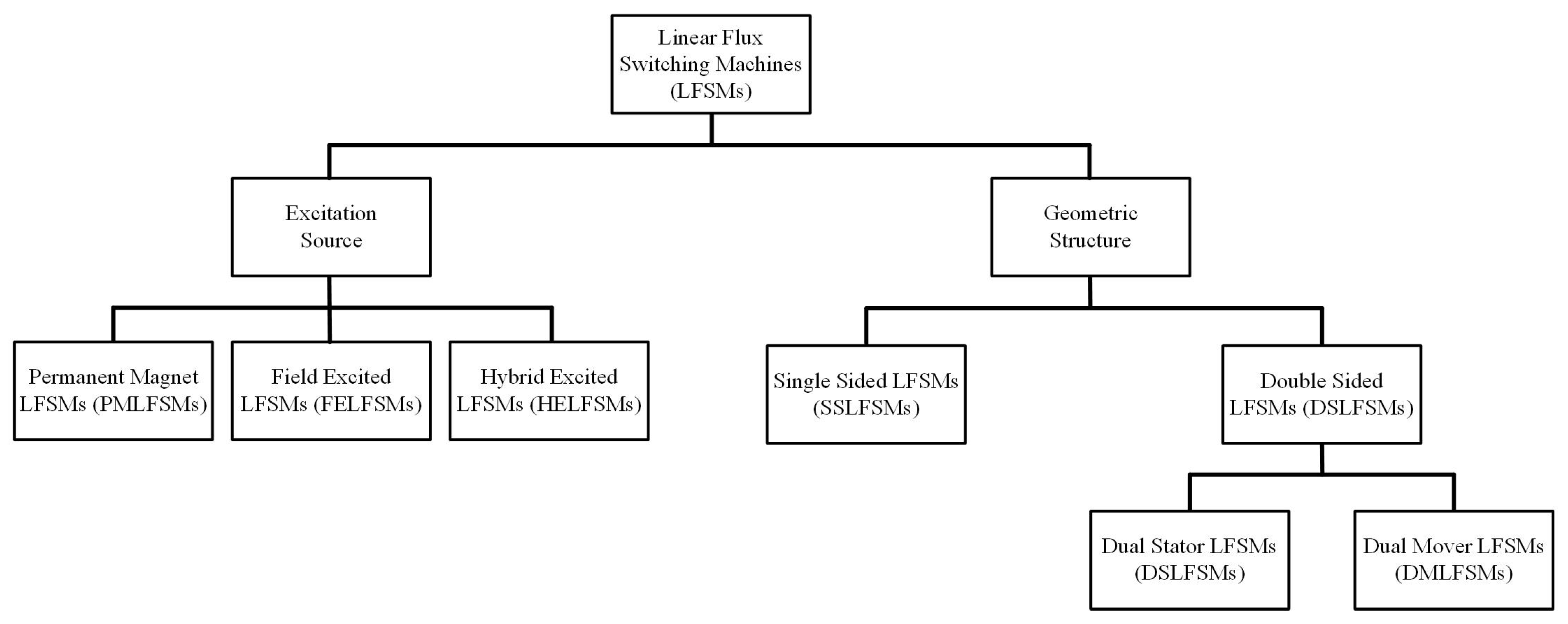
LFSMs may be categorized in accordance to their excitation sources and physical structure (Figure 2). Based on geometry, they are classified into double-sided and single-sided configurations [15]. Single-sided machines, which are directly derived from their rotatory counterparts, have experienced limited industrial adoption due to their excessive normal forces [16]. These forces increase friction in linear bearings, thus degrading thrust output, efficiency, and operational reliability [17]. With respect to excitation, LFSMs are classified as Permanent Magnet LFSMs (PMLFSMs) [17], Field-Excited LFSMs (FELFSMs) [18], and Hybrid-Excited LFSMs (HELFSMs) [19]. In PMLFSMs and FELFSMs, magnetic flux is generated primarily by PMs and FECs, respectively, whereas HELFSMs combine PMs, FECs, and AC excitation to achieve improved electromagnetic performance [20].
Two significant limitations of PMLFSMs—namely the high manufacturing cost resulting from the escalating prices of Neodymium (Nd) and Dysprosium (Dy), and the lack of control over air-gap flux density—have been effectively mitigated through the introduction of FELFSMs [21]. Nevertheless, FELFSMs exhibit a major drawback in the form of low thrust force density, as demonstrated by analytical studies [22]. HELFSMs successfully address both the cost and flux controllability issues associated with PMLFSMs, while simultaneously improving the inherently low thrust force performance of FELFSMs.
With respect to the passive secondary geometry, LFSMs can be categorized into uniform secondary and segmented secondary configurations. Comparative studies indicate that segmented secondary structures provide superior performance, including shorter low-reluctance flux paths, reduced thrust force ripple ratio (TFRR) and stator material consumption [23,24,25].
A Double-Sided PMLFSM is analyzed in [26] with respect to normal force, efficiency, and power factor. The results indicate that DSPMLFSMs exhibit relatively low normal force, high thrust force density, and low thrust ripples, demonstrating their suitability for long-stroke applications. In [27], two Double-Sided FELFSMs with series and parallel magnetic circuits are compared. The comparative analysis reveals that the LFSM with a series magnetic circuit produces more sinusoidal back-EMF, higher thrust force density, and greater load-carrying capability.
Similarly, a comparative study between a Single-Sided SSFELFSM and an LSRM presented in [28] shows that the LSRM exhibits higher thrust ripple, and its average thrust force is approximately 60% lower than that of the LFSM. In [29], a novel DSPMLFSM topology featuring a long primary with excitation sources and a short moving passive secondary is proposed and investigated. Furthermore, another dual-primary DSPMLFSM is studied in [30] and quantitatively compared with three different LIMs. The findings demonstrate that the DSPMLFSM offers several advantages, including high efficiency, high power factor, robust secondary structure, low inductance, large thrust force, and reduced force ripple.
The primary objective of this research is to design, analyze, and compare two novel Segmented Secondary Hybrid Excited Linear Flux Switching Machines (SSHELFSMs) with dual-mover and dual-stator topology, incorporating complementary coil arrangements and a combined series–parallel magnetic circuit. The proposed double-sided topology eliminates the undesired normal or attraction forces commonly observed in single-sided designs. The dual-excitation feature, utilizing both permanent magnets and electromagnets, reduces permanent magnet material consumption and enables effective flux weakening and strengthening control. Moreover, the segmented secondary structure provides shorter low-reluctance paths for flux linkage and reduces secondary material usage. In addition, the complementary coil design and combined magnetic circuit configuration result in more symmetrical and sinusoidal flux waveforms, leading to a significant reduction in TFRR. Holistic comparison of the two aforementioned topologies explained that dual-stator topology exhibits better performance with higher and more sinusoidal flux linkage, higher thrust force, and robust mechanical structure.
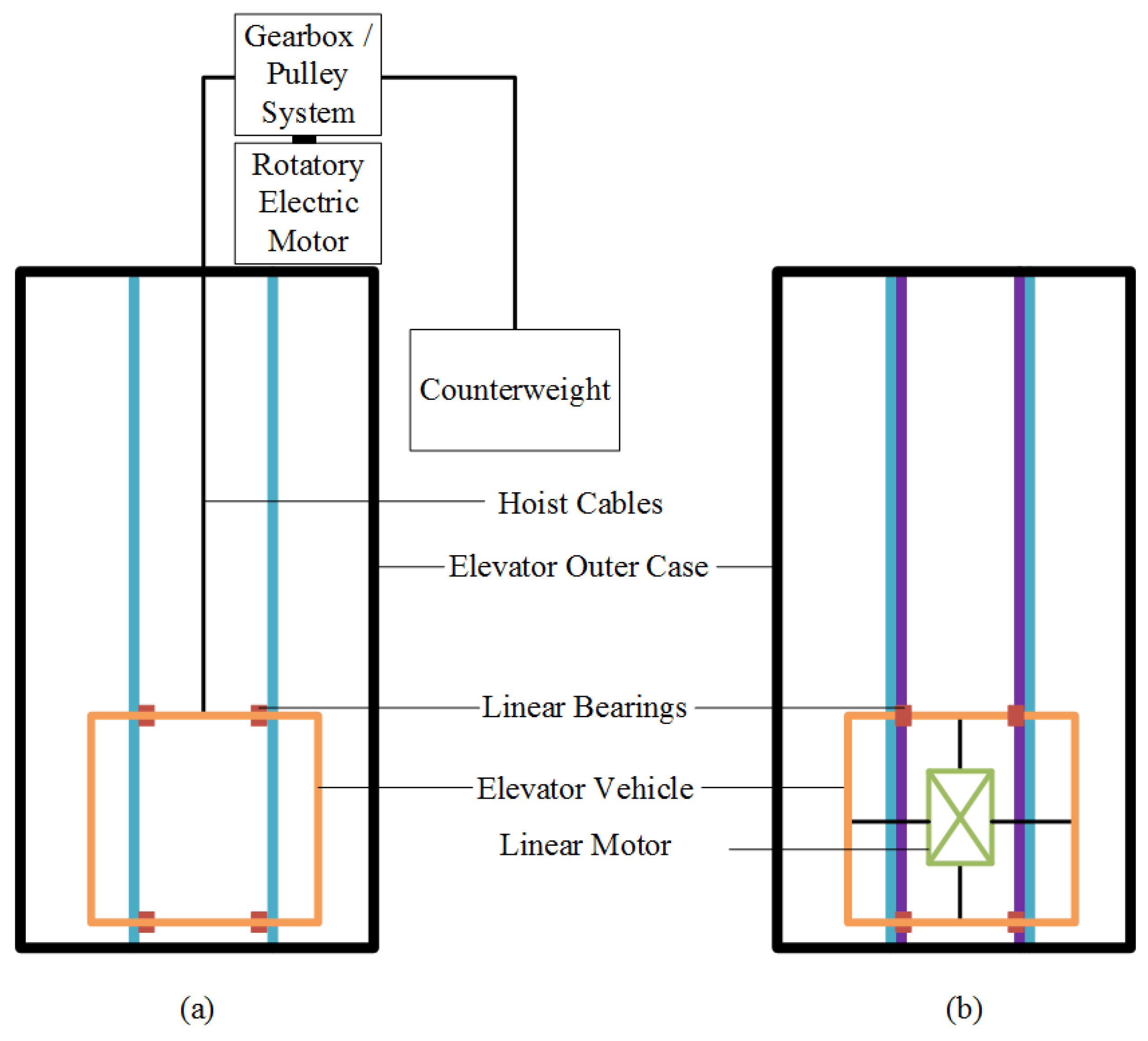
Figure 3 shows a schematic diagram of an existing vertical elevator topology and a suggested corresponding solution using a linear motor instead of a rotatory electric motor. The excitation sources of the linear motor will be placed with the passenger vehicle and the passive stator part will be attached with the linear bearing rods. This solution will also eliminate the requirements for lift cables and counterweights.
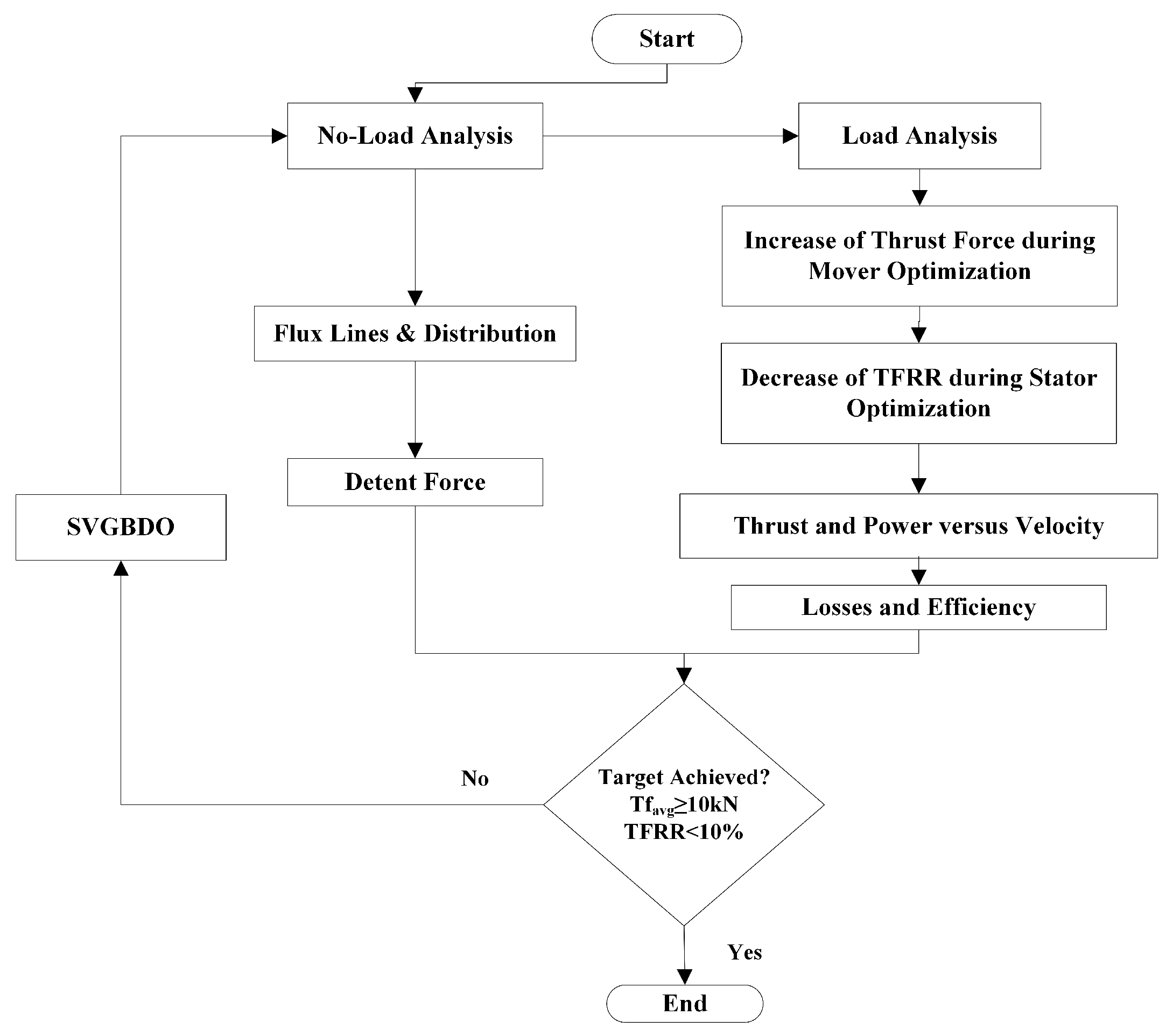
The second objective of this research is to geometrically optimize the selected linear machine while maintaining an average thrust force of 10kN and a TFRR of less than 10%. The Single-Variable Geometry-Based Determination Optimization (SVGBDO) approach is applied to achieve these performance constraints. A holistic comparison of performance parameters, along with waveforms and the changed geometric parameters of the initial and optimized machines, is also explained.
Thirdly and lastly, a full-scale prototype was manufactured and tested under no-load conditions in a standard laboratory environment. The B-EMF and detent force waveform of the optimized linear machine obtained from FEA are experimentally validated. Good agreement between the simulated and measured results verified the theoretical research.
The rest of the paper is organized as follows: Section 2 presents the design methodology of the proposed machines. A holistic comparison of the proposed machines is presented in Section 3. The utilized optimization approach is explained in Section 4, and hardware validation is presented in Section 5.

2. Design Methodology

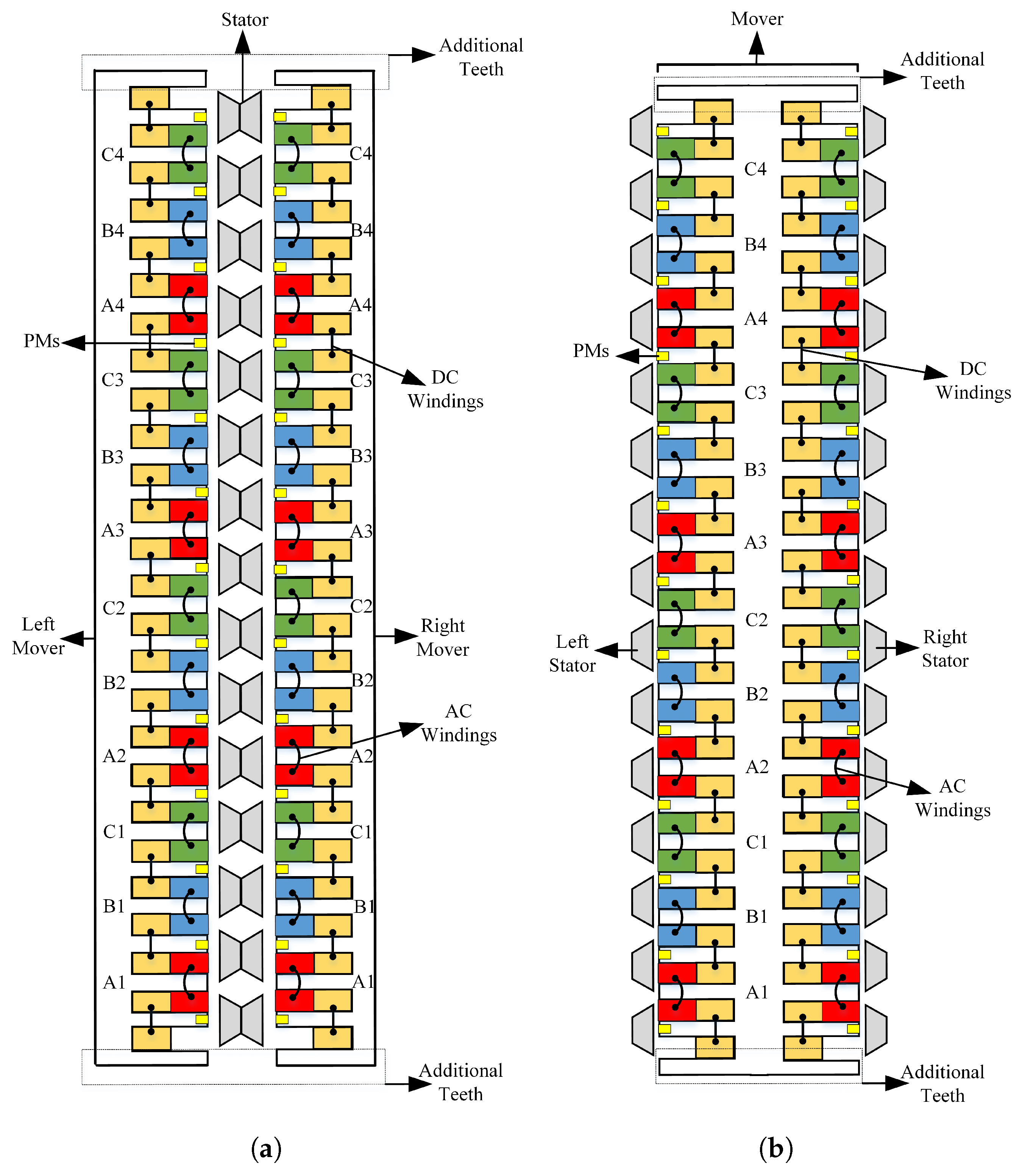
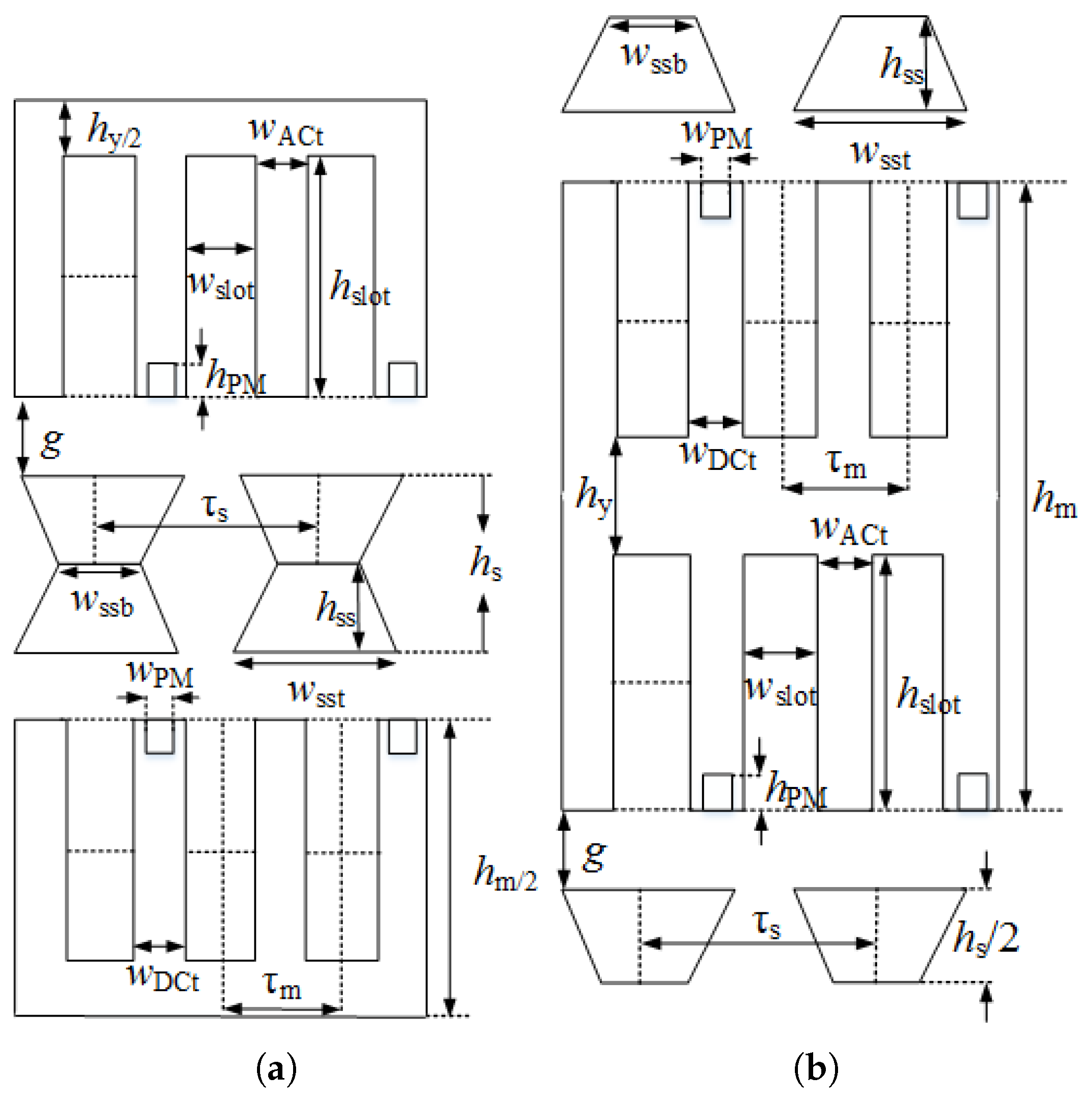
Two-dimensional schematic diagrams of the DMSSHELFSM and DSSSHELFSM are presented in Figure 4. The nomenclature of geometric parameter variables is shown in Figure 5. Complementary winding arrangement analytical equations are listed as Equations (1)–(4). Numerical values of geometric parameter variables are listed in Table 1.
N u m b e r - o f - M o v e r - t e e t h = 4 x y + 1
N u m b e r - o f - P M / D C - C o i l s = 2 x y + 1
N u m b e r - o f - A C - C o i l s = 2 x y
τ s / τ m = 4 x y / ( 2 x y + 2 )
where x represents AC phase number and y represents each AC phase winding pair repetition in the machine. Twenty-six PM pieces, forty-eight AC winding slots, and fifty-two DC winding slots were designed to ensure complementary coil structure. The purpose of the assistant teeth is to reduce the end effect.

3. Holistic Comparison

A holistic comparison of the proposed HELFSMs is presented in this section. Five KPIs, i.e., (a) peak-to-peak open-circuit flux linkage and corresponding THD, (b) detent force, (c) average thrust force, (d) TFRR, and (e) normal force, were selected for comparison.

3.1. No-Load Flux Linkage

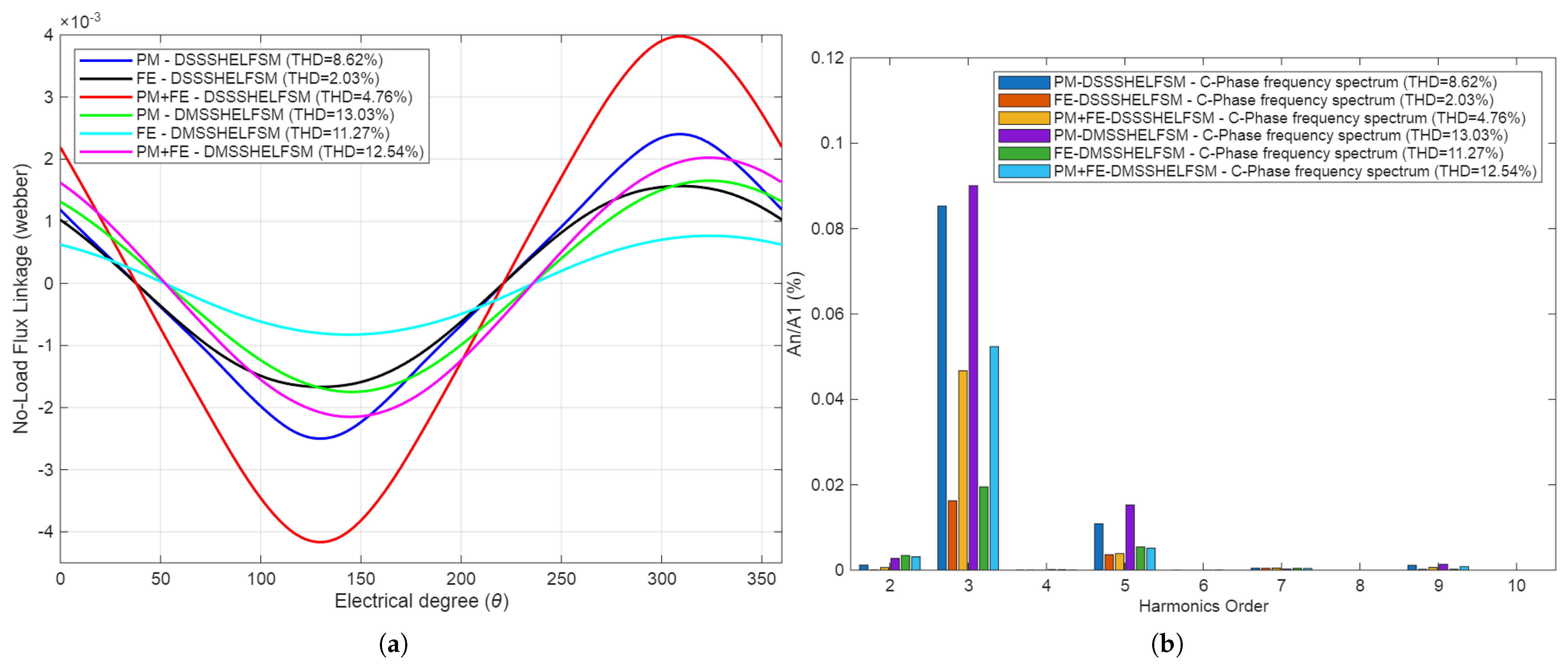
Comparisons of the open-circuit flux linkage waveforms of the proposed SSHELFSMs and their corresponding frequency spectrum plots are shown in Figure 6. It can be seen that peak-to-peak flux linkage of DSSSHELFSM is greater in magnitude, more sinusoidal, and more symmetrical when compared with DMSSHELFSM. The magnitude of peak-to-peak flux linkage of DSSSHELFSM under only PM excitation is 4.88 mWb, under FE excitation alone is 3.20 mWb, and under hybrid excitation its value is 8.10 mWb, whereas the magnitude of peak-to-peak flux linkage of DMSSHELFSM under only PM, only FE, and under hybrid excitation is 3.40 mWb, 1.59 mWb, and 4.17 mWb, respectively. The frequency spectrum of both machines also depicts that THD of DSSSHELFSM is less under all excitation schemes. Hence, DSSSHELFSM will be a better choice when comparing no-load flux linkage.

3.2. Detent Force

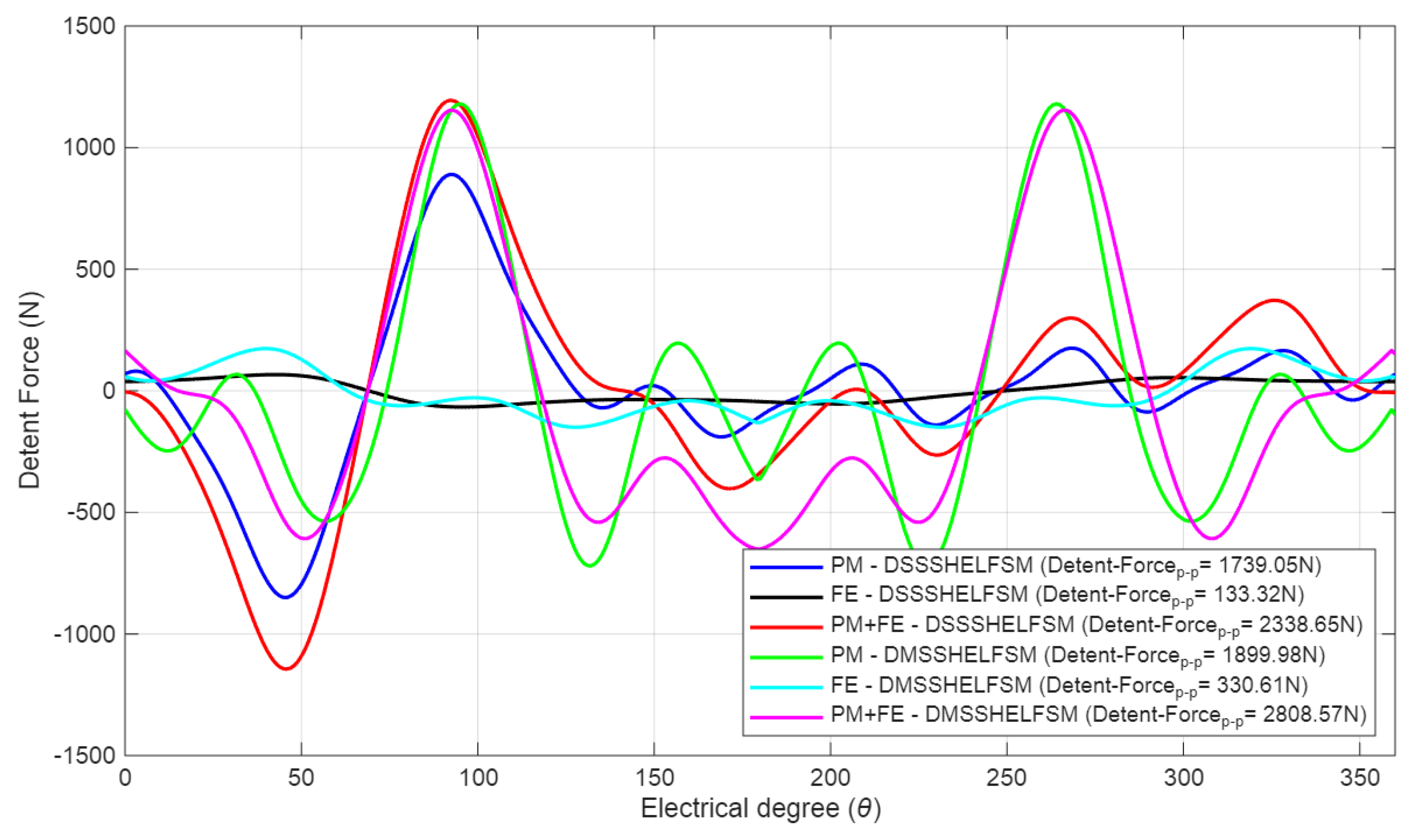
Detent force waveforms of the proposed DMSSHELFSM and DSSSHELFSM are compared in Figure 7. It can be seen that the detent force of DMSSHELFSM is greater in magnitude, and reflects two spikes. Detent force produces fluctuations in thrust force profile. These two spikes of DMSSHELFSM will deteriorate ride of the elevator system. Magnitude of peak-to-peak detent force of DSSSHELFSM under only PM excitation is 1739.05 N, under only FE excitation is 133.32 N, and under hybrid excitation its value is 2338.65 N. In contrast, magnitude of peak-to-peak detent force of DMSSHELFSM under only PM, only FE, and under hybrid is 1899.98 N, 330.61 N, and 2808.57 N, respectively. Hence, the detent force profile pushed the researchers to go with DSSSHELFSM.

3.3. Thrust Force and TFRR

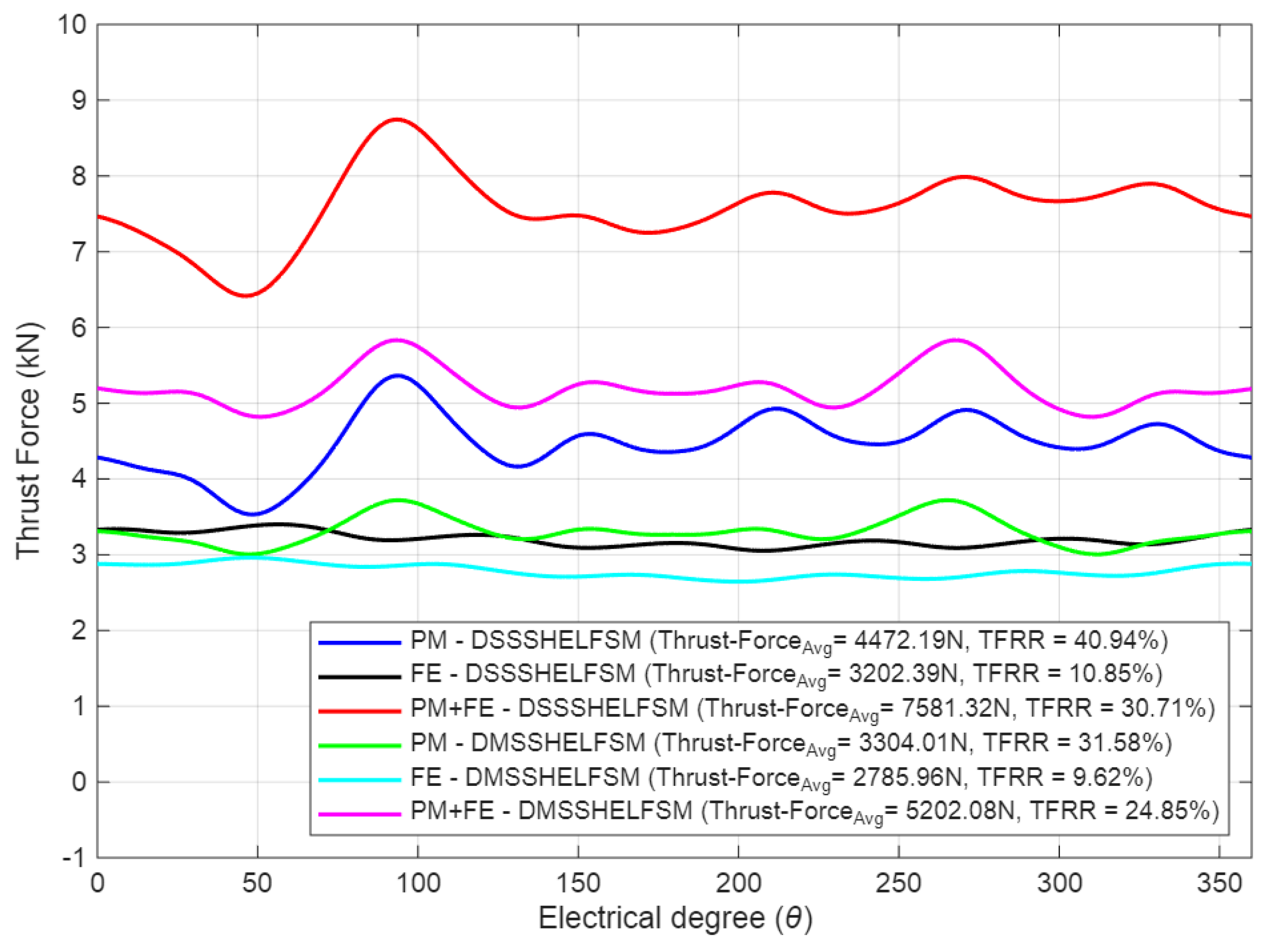
Thrust force waveforms of the proposed DMSSHELFSM and DSSSHELFSM are compared in Figure 8. It can be seen that average value of thrust force of DSSSHELFSM under only PM excitation is 4472.19 N, under only FE excitation is 3202.39 N, and under hybrid excitation its value is 7581.32 N. The corresponding TFRRs are 40.94%, 10.85%, and 30.71%, respectively. The effect of the two spikes witnessed in the detent force profile of DMSSHELFSM can be properly seen in the thrust force profile and result in average thrust force values of 3304.01 N under PM excitation, 2785.96 N under FE excitation, and 5202.08 N under hybrid excitation. The corresponding TFRRs are 31.58%, 9.62%, and 24.85%, respectively. It is true that the TFRR values of DMSSHELFSM are less than those of DSSSHELFSM. However, average thrust force values of DSSSHELFSM are significantly greater than those of DMSSHELFSM. Hence, greater average thrust force values compelled the designers to select DSSSHELFSM as a better machine.

3.4. Normal Force

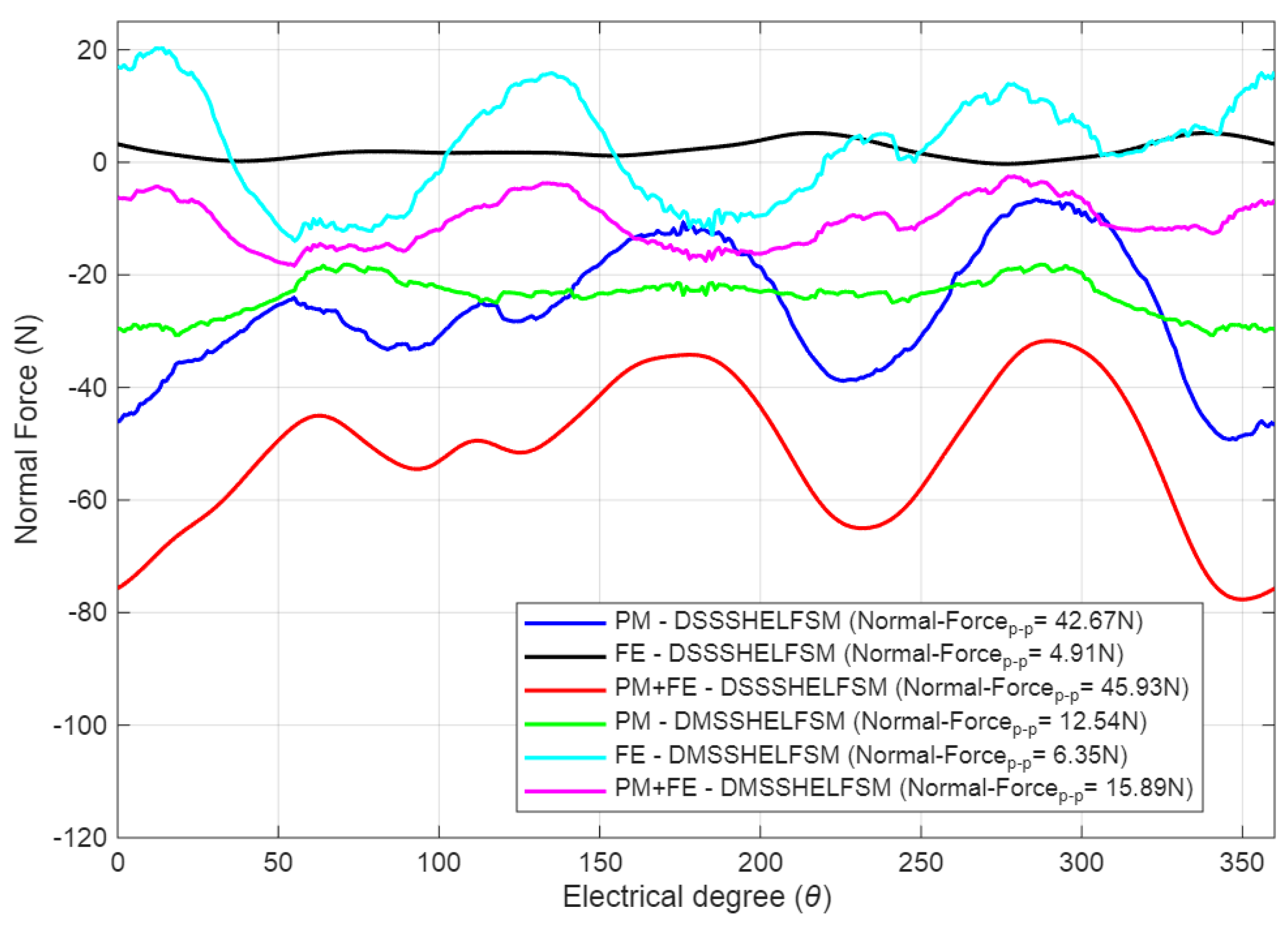
Normal force waveforms of the proposed DMSSHELFSM and DSSSHELFSM are compared in Figure 9. Normal force exerts extra frictional forces and reduces system reliability. The normal force profile of DMSSHELFSM is better than that of DSSSHELFSM. Peak-to-peak normal force of DSSSHELFSM under only PM excitation is 42.67 N, under only FE excitation is 4.91 N, and under hybrid excitation its value is 45.93 N. In contrast, the magnitudes of peak-to-peak normal force of DMSSHELFSM under only PM, only FE, and under hybrid are 12.54 N, 6.35 N, and 15.89 N, respectively.
Based on detailed analysis, DSSSHELFSM was selected as a suitable candidate and subjected to the optimization process.

4. Design Optimization

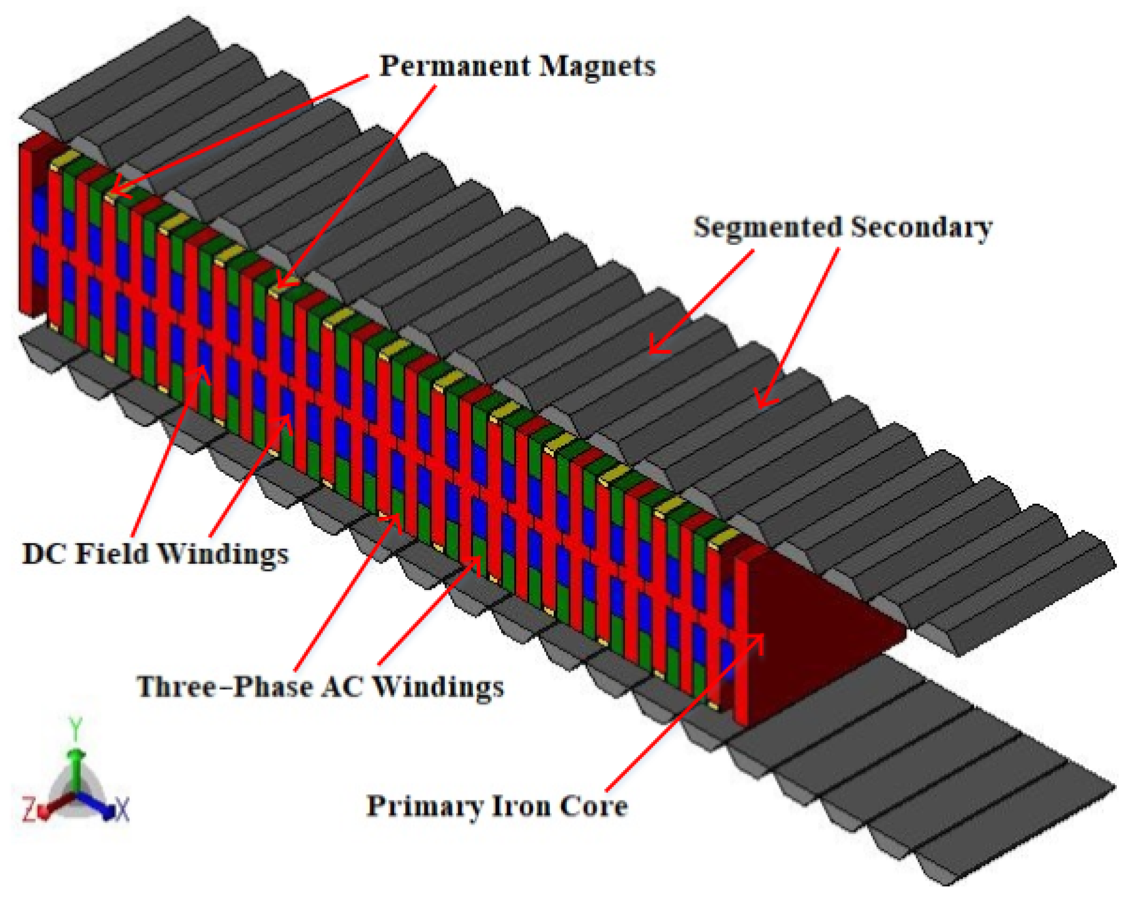
The three-dimensional representation of the proposed DSSSHELFSM is illustrated in Figure 10. The SVGBDO-based optimization framework is executed in two sequential phases: mover optimization and stator optimization. The first phase aims to enhance the average thrust force, while the second phase seeks to minimize the TFRR subject to a predefined average thrust force constraint.

4.1. SVGBDO

The optimization objectives and overall implementation strategy of the SVGBDO approach are depicted in Figure 11. The black encircled region represents the performance of the baseline machine configuration, while the green rectangle indicates the optimized values of the optimization coefficients. In accordance with the optimization objectives, split ratio, AC and DC coil slot area, PM dimensions, unequal primary tooth width, stator segment tip and base width are optimized by defining the following six optimization coefficients.
S . R = h s + 2 · g h s + 2 · g + h m
K slotdim = w slot h slot
P M d i m = w P M h P M
U T -Width = w A C t w D C t
K S S T W = w s s t τ s
K S S B W = w s s b w s s t

4.1.1. Split Ratio Optimization

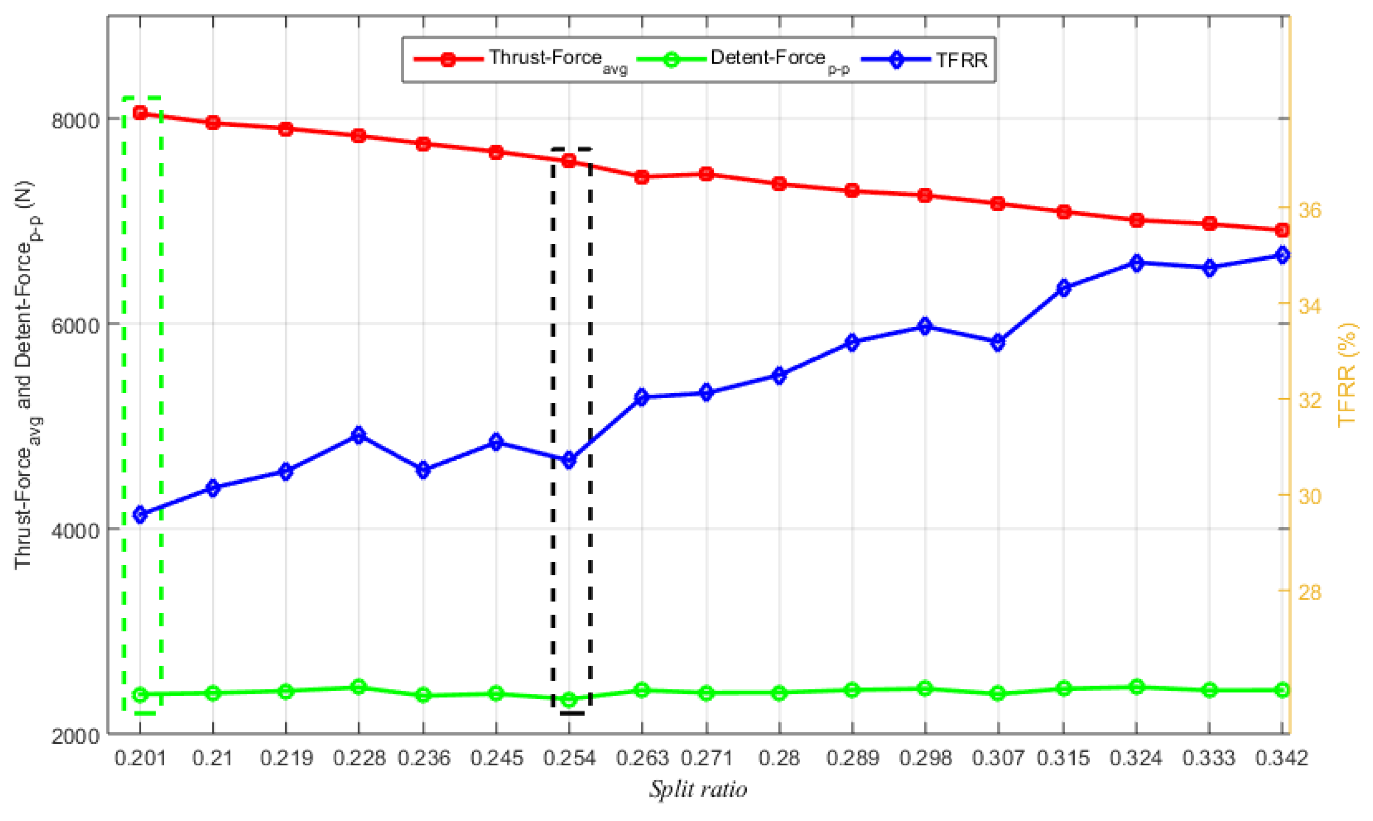
Results obtained by simulating various split ratio combinations are compared in Figure 12. The highest value of average thrust force is achieved with a split ratio coefficient of 0.201 and is selected as the optimized value. The no-load peak-to-peak flux linkage, corresponding THD, peak-to-peak detent force, average thrust force, TFRR, and peak-to-peak normal force of the black encircled region (initial configuration) were recorded as 8.10 mWb, 4.76%, 2338.65 N, 7581.32 N, 30.71%, and 45.93 N, respectively, whereas comparative values of the green encircled region (split-ratio-optimized configuration) were recorded as 8.58 mWb, 4.59%, 2386.50 N, 8048.43 N, 29.58%, and 41.57 N, respectively.

4.1.2. Slot Area Dimension Optimization

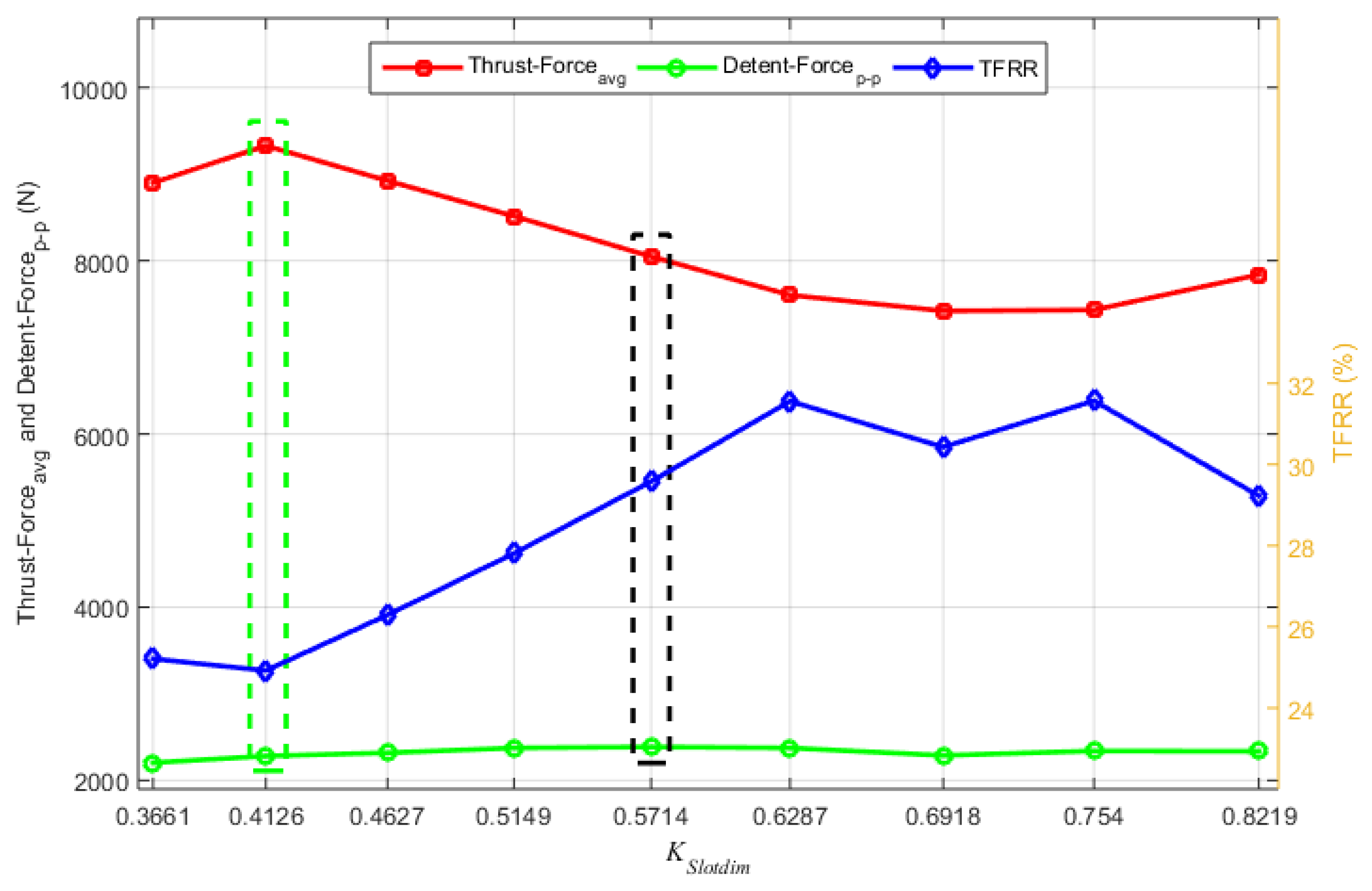
Results obtained by simulating various slot area dimension coefficients are presented in Figure 13. The highest value of average thrust force was achieved with a slot area coefficient of 0.4126 and was selected as optimized value. The no-load peak-to-peak flux linkage, corresponding THD, peak-to-peak detent force, average thrust force, TFRR, and peak-to-peak normal force of the black encircled region (split-ratio-optimized configuration) were recorded as 8.58 mWb, 4.59%, 2386.50 N, 8048.43 N, 29.58%, and 41.57 N, respectively. In contrast, comparative values of the green encircled area (slot area dimension-optimized configuration) were recorded as 9.07 mWb, 4.04%, 2281.47 N, 9328.35 N, 24.92%, and 88.58 N, respectively.

4.1.3. PM Dimension Optimization

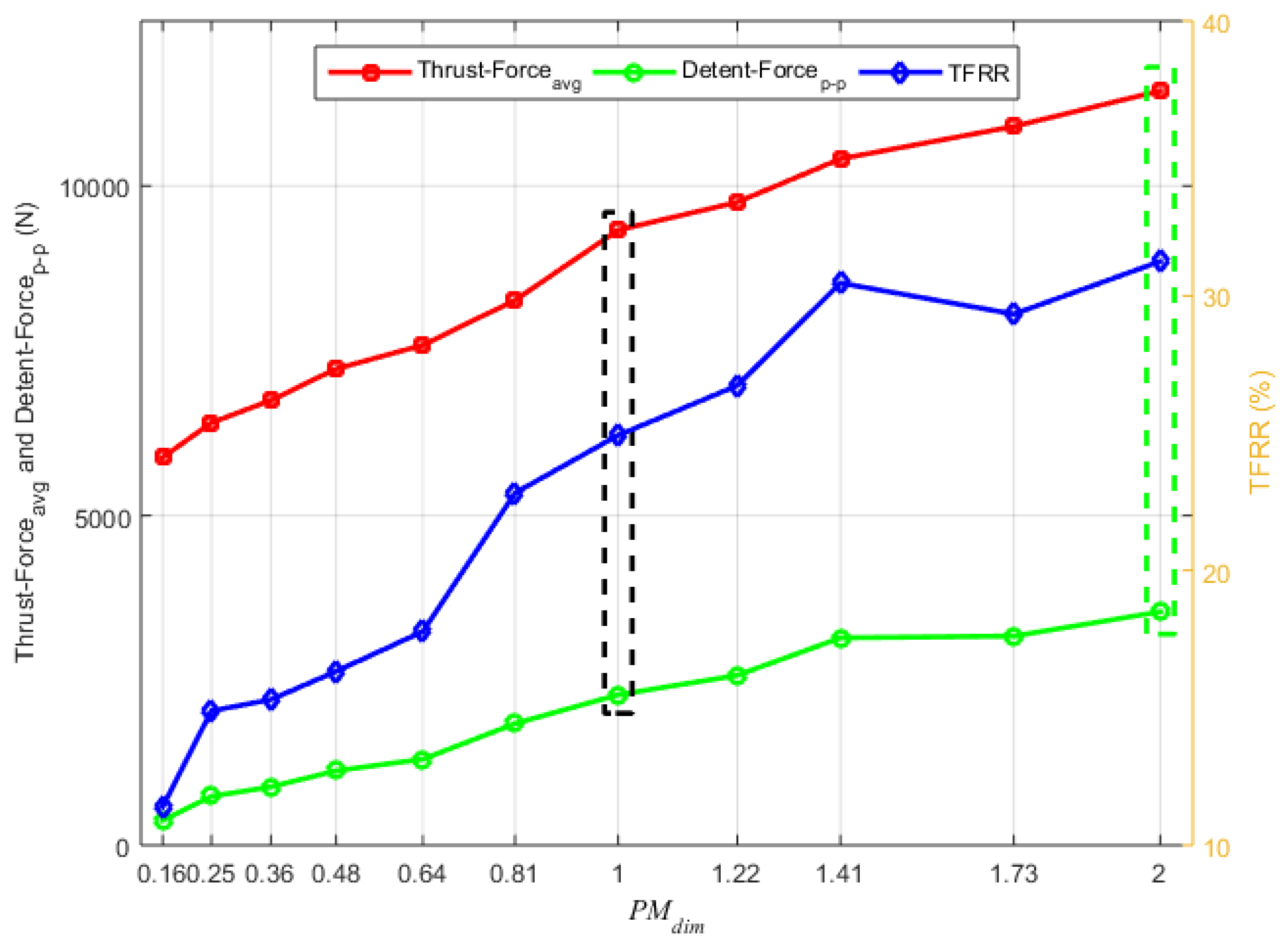
Results obtained by simulating various PM dimension coefficients are compared in Figure 14. The highest value of average thrust force was achieved with a PM dimension coefficient of 2.00 and was selected as the optimized value. The no-load peak-to-peak flux linkage, corresponding THD, peak-to-peak detent force, average thrust force, TFRR, and peak-to-peak normal force of the black encircled region (slot area dimension-optimized configuration) were recorded as 9.07 mWb, 4.04%, 2281.47 N, 9328.35 N, 24.92%, and 88.58 N, respectively. In contrast, comparative values of the green encircled area (PM-dimension-optimized configuration) were recorded as 11.92 mWb, 2.86%, 3540.44 N, 11,441.09 N, 31.25%, and 10.68 N, respectively.

4.1.4. Unequal Primary Tooth Width Optimization

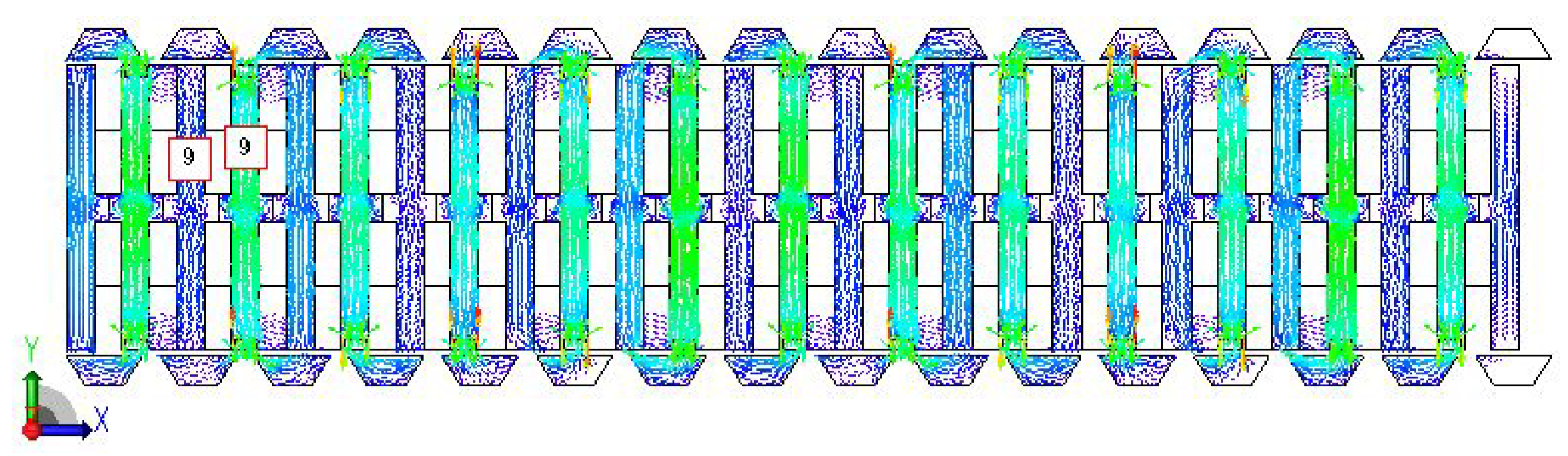
Figure 15 illustrates the magnetic flux lines of the DSSSHELFSM after optimization of PM dimensions. Detailed analysis indicates that the primary teeth containing both PMs and FECs exhibit a higher flux density compared to the AW teeth. To convert these highly populated primary teeth into low-reluctance paths and improve the utilization ratio of the primary core, the Unequal Tooth Width Optimization (UTWO) coefficient is defined, as given in Equation (8).
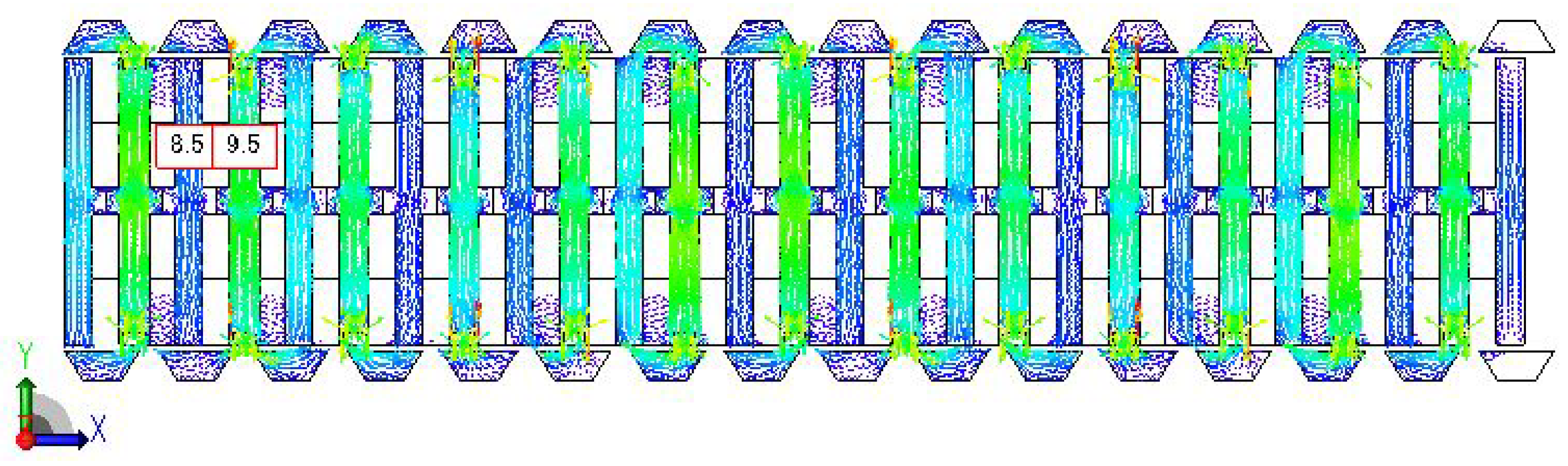
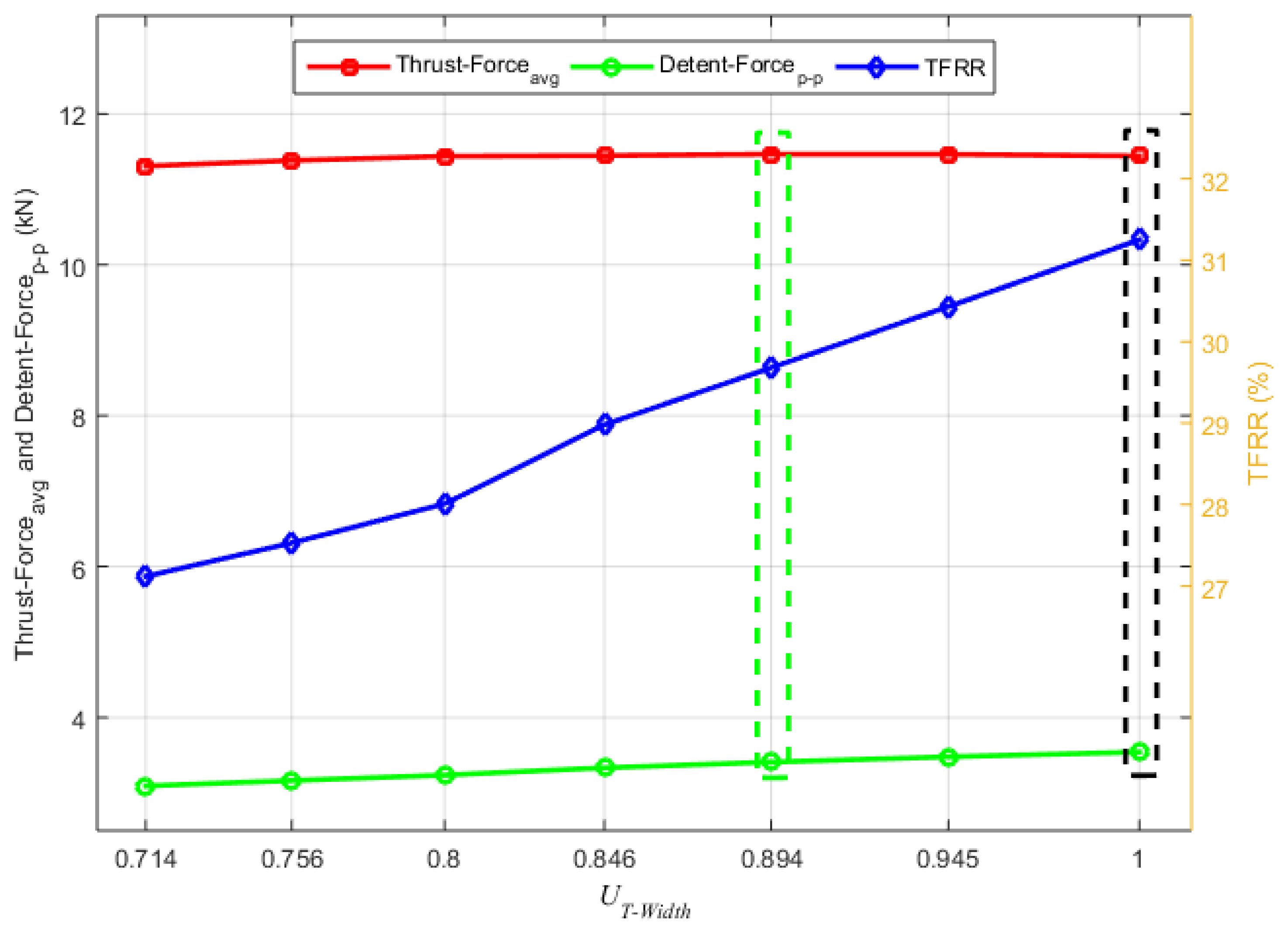
Output of KPIs under different UTWO coefficient are compared and presented in Figure 16. The maximum average thrust force is achieved with a UTWO coefficient of 0.894 and was selected as optimized value. The no-load peak-to-peak flux linkage, corresponding THD, peak-to-peak detent force, average thrust force, TFRR, and peak-to-peak normal force of the black encircled region (PM-dimension-optimized configuration) were recorded as 11.92 mWb, 2.86%, 3540.44 N, 11,441.09 N, 31.25%, and 10.68N, respectively. In contrast, comparative values of the green encircled region (UTWO-coefficient-optimized configuration) were recorded as 11.75 mWb, 2.70%, 3407.63 N, 11,464.85 N, 29.68%, and 9.02 N, respectively. Hence, novelty of unequal primary tooth width is successfully realized. On-load magnetic flux lines of DSSSHELFSM with unequal primary teeth width are shown in Figure 17. Mover optimization is summarized in this subsection.

4.1.5. Stator Segment Tip Width Optimization

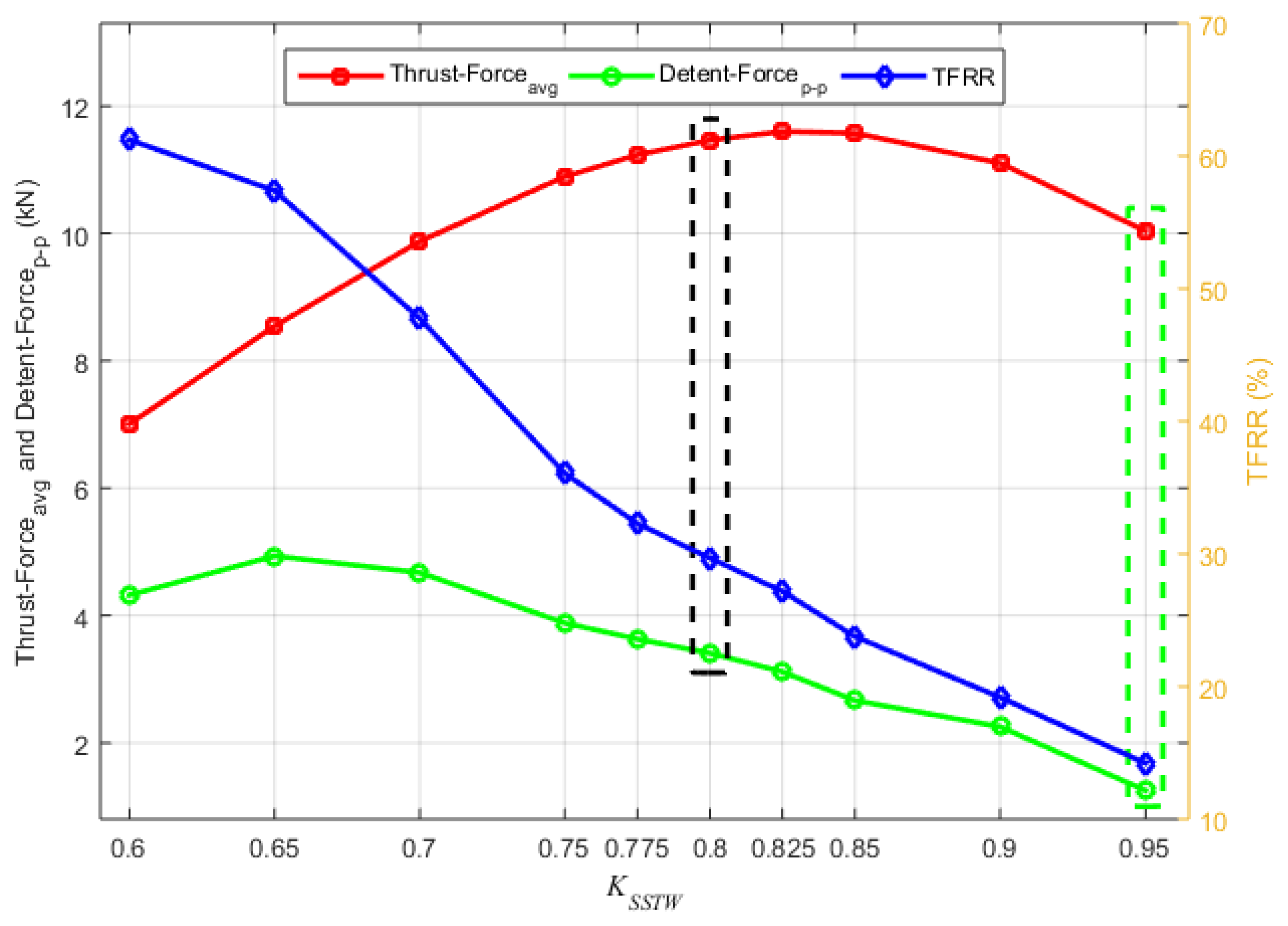
Output of KPIs under different Stator Segment Tip Width (SSTW) coefficient combinations are compared and presented in Figure 18. The minimum TFRR while maintaining average thrust force of 10 kN was achieved with an SSTW coefficient of 0.95 and was selected as the optimized value. The no-load peak-to-peak flux linkage, corresponding THD, peak-to-peak detent force, average thrust force, TFRR, and peak-to-peak normal force of the black encircled region (UTWO-coefficient-optimized configuration) were recorded as 11.75 mWb, 2.70%, 3407.63 N, 11,464.85 N, 29.68%, and 9.02 N, respectively. In contrast, comparative values of the green encircled region (SSTW-coefficient-optimized configuration) were recorded as 10.71 mWb, 1.22%, 1251.65 N, 10,038.52 N, 14.23%, and 7.95 N, respectively.

4.1.6. Stator Segment Base Width Optimization

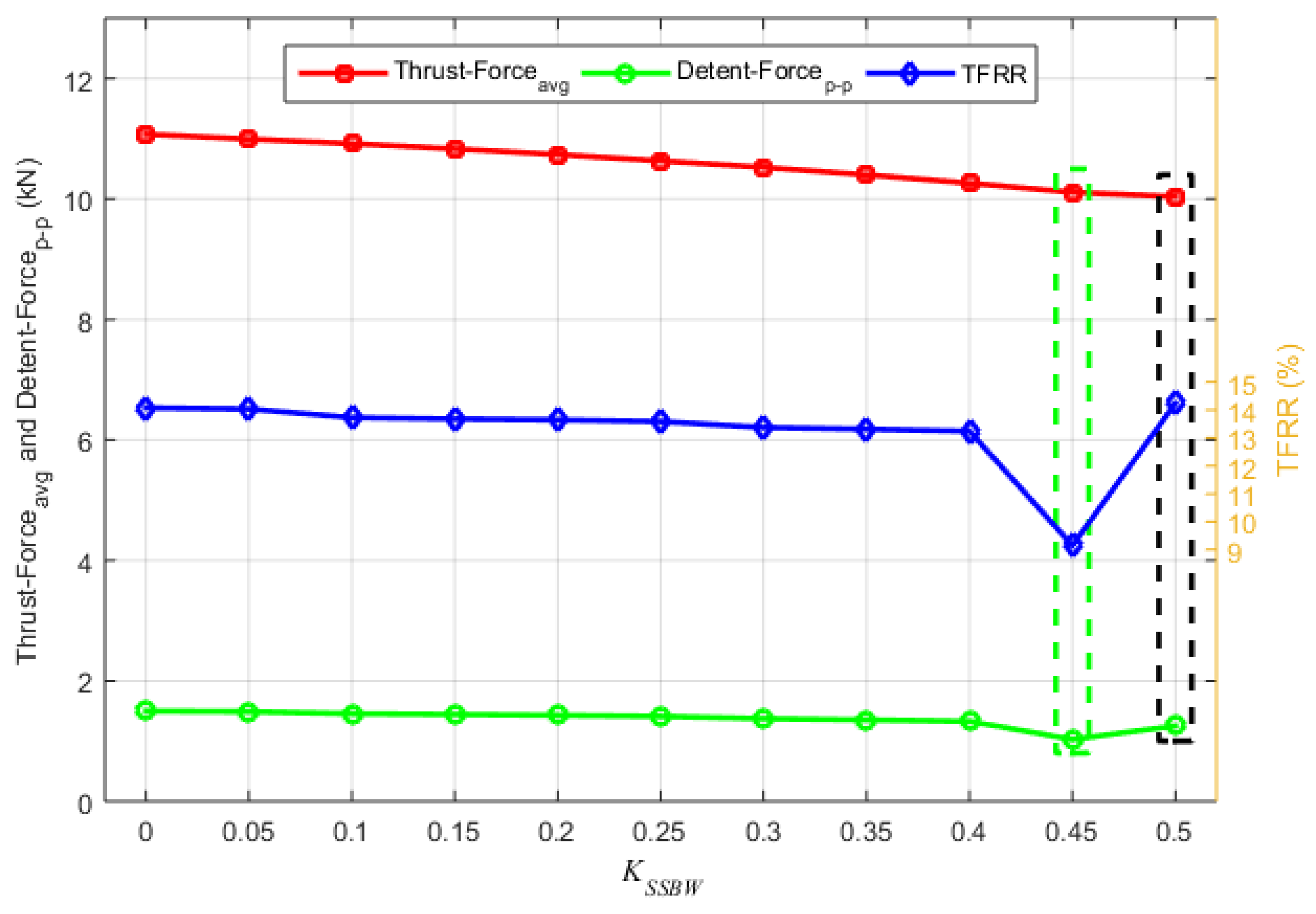
Output of KPIs under different Stator Segment Base Width (SSBW) coefficient combinations are compared and presented in Figure 19. The minimum TFRR while maintaining average thrust force of 10 kN was achieved with an SSBW coefficient of 0.45 and was selected as the optimized value. The no-load peak-to-peak flux linkage, corresponding THD, peak-to-peak detent force, average thrust force, TFRR, and peak-to-peak normal force of the black encircled region (SSTW coefficient optimized configuration) were recorded as 10.71 mWb, 1.22%, 1251.65 N, 10,038.52 N, 14.23%, and 7.95 N, respectively. In contrast, comparative values of the green encircled region (SSBW coefficient optimized configuration) were recorded as 10.90 mWb, 1.17%, 1028.83 N, 10,111.13 N, 9.15%, and 8.19 N, respectively.

4.2. Comparison of Initial and Optimized DSSSHELFSM

A holistic comparison of the initial and geometrically optimized DSSSHELFSM is presented in this subsection. A detailed comparison is done to validate the optimization approach.

4.2.1. No-Load Flux Linkage

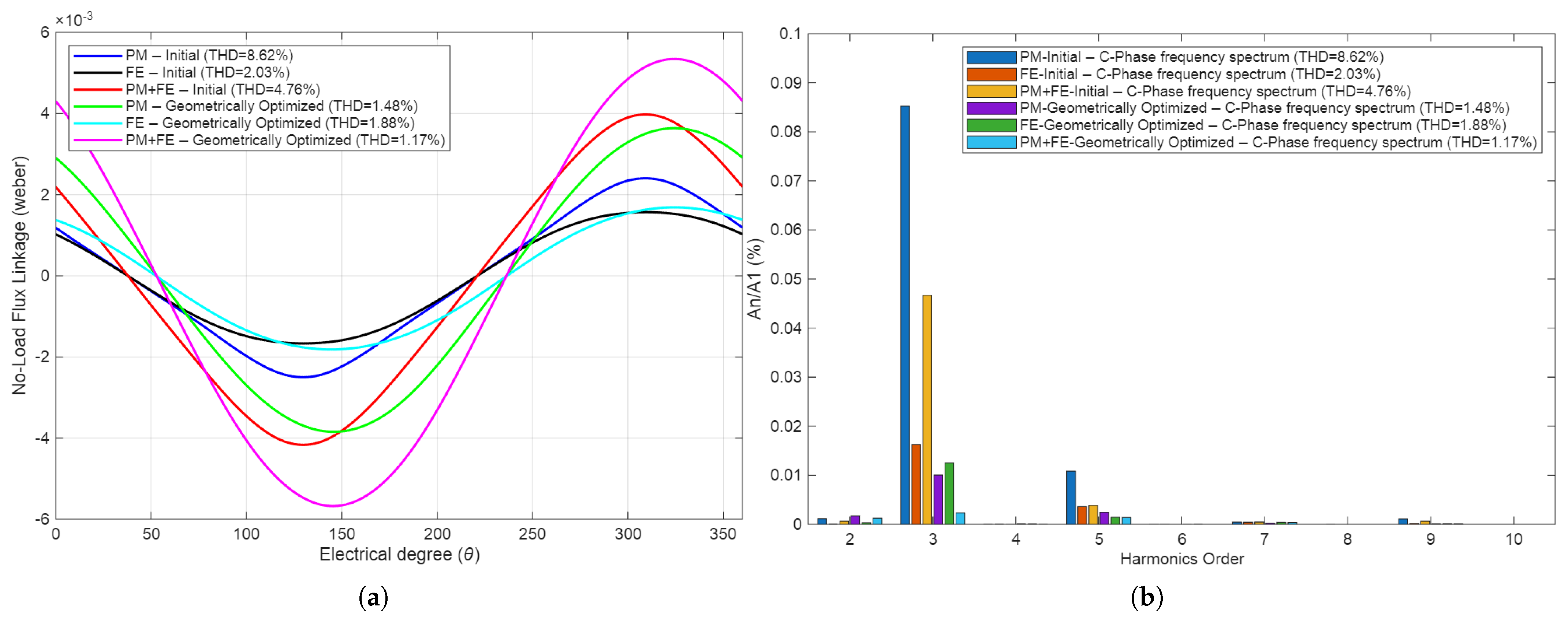
Comparisons of open-circuit flux linkage waveforms of the initial and geometrically optimized DSSSHELFSM and their corresponding frequency spectrum plots are shown in Figure 20. It can be seen that the peak-to-peak flux linkage of the geometrically optimized DSSSHELFSM is greater in magnitude, more sinusoidal, and more symmetrical. The magnitude of peak-to-peak flux linkage of the initial DSSSHELFSM under only PM excitation is 4.88 mWb, under only FE excitation is 3.20 mWb, and under hybrid excitation its value is 8.10 mWb. In contrast, the magnitudes of peak-to-peak flux linkage of the geometrically optimized DSSSHELFSM under only PM, only FE, and under hybrid excitation are 7.41 mWb, 3.45 mWb, and 10.90 mWb, respectively. The frequency spectra of both machines also depict that THD of the geometrically optimized DSSSHELFSM is less under all excitation schemes. Dominant third and fifth order harmonics are suppressed by the optimization approach, resulting in reduced THD of 1.48%, 1.88%, and 1.17% for only PM, only FE, and hybrid excitation, respectively.

4.2.2. Detent Force

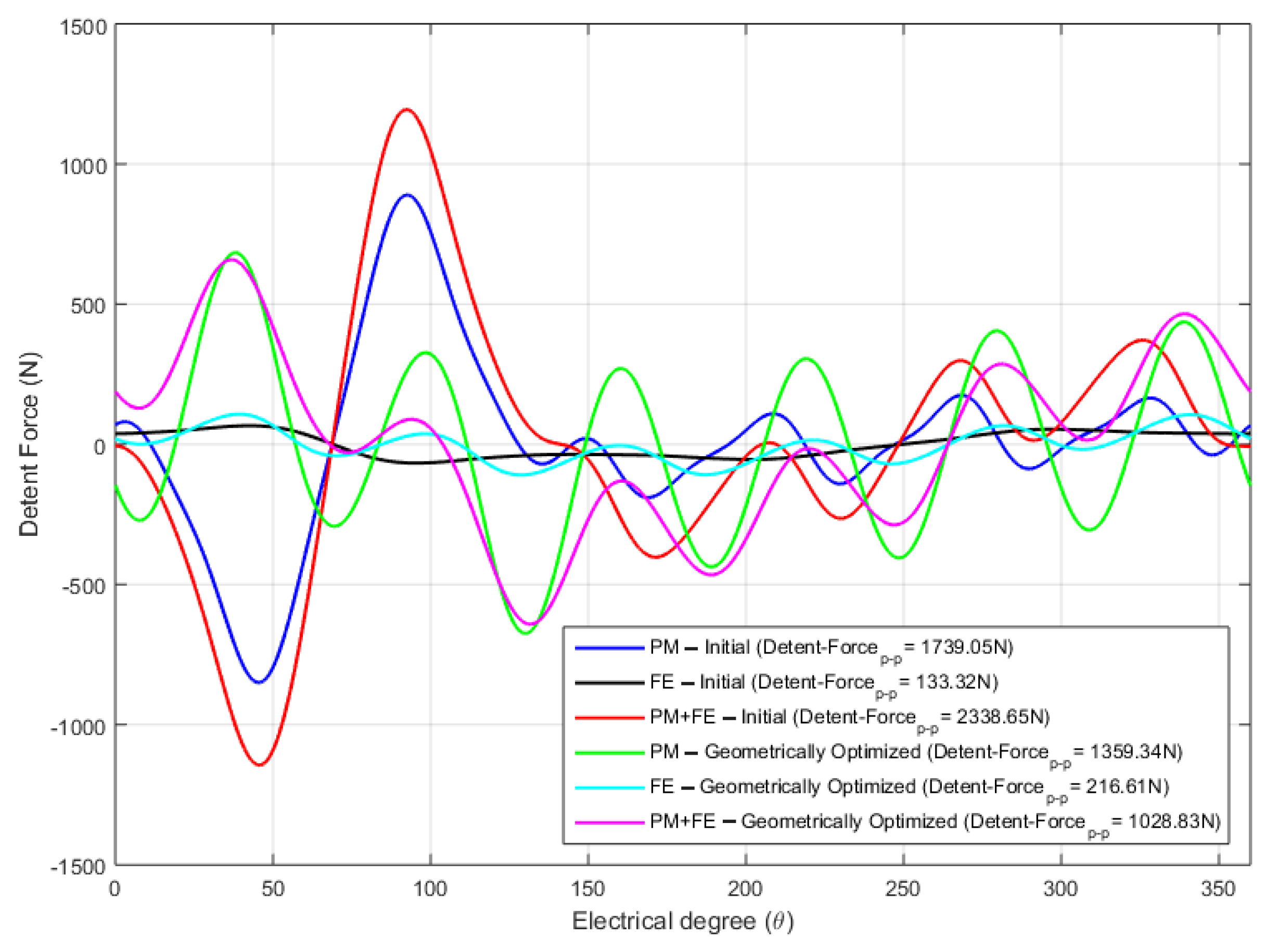
Comparison of detent force waveforms of the initial and geometrically optimized DSSSHELFSM is done in Figure 21. It can be seen that peak-to-peak detent force of DSSSHELFSM is effectively curtailed from 1739.05 N to 1359.34 N under only PM excitation and from 2338.65 N to 1028.83 N under hybrid excitation. In contrast, magnitude of peak-to-peak detent force under only FE excitation is increased from 133.32 N to 216.61 N.

4.2.3. Thrust Force and TFRR

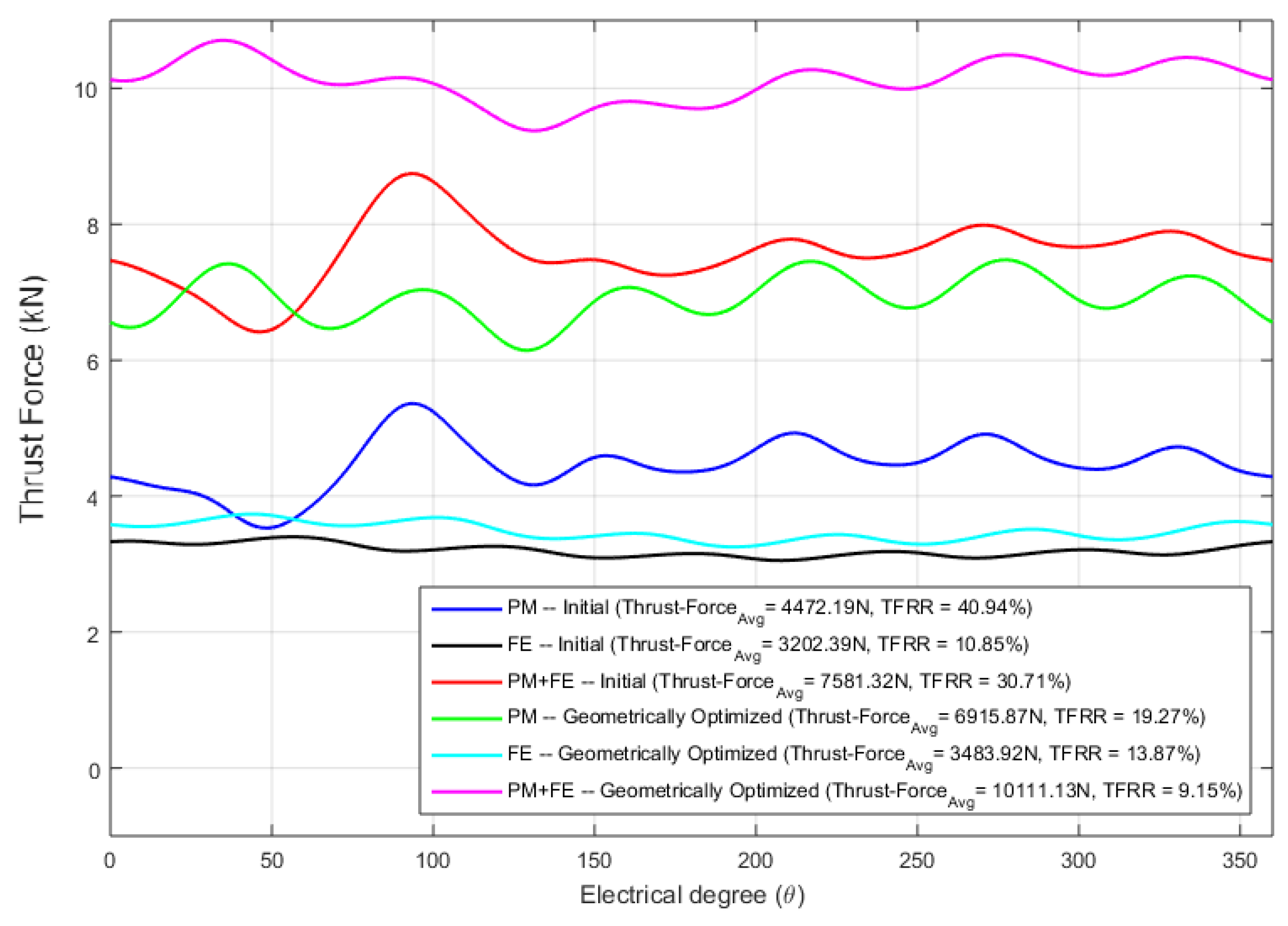
Comparison of thrust force waveforms of the initial and geometrically optimized DSSSHELFSMs is shown in Figure 22. It can be seen that average value of thrust force of DSSSHELFSM was successfully increased from 4472.19 N to 6915. 87 N under only PM excitation, from 3202.39 N to 3483.92 N under only FE excitation, and from 7581.32 N to 10,111.13 N under hybrid excitation. TFRR of DSSSHELFSM was successfully reduced from 40.94% to 19.27% under only PM excitation and from 30.71% to 9.15% under hybrid excitation. TFRR of the geometrically optimized DSSSHELFSM is relatively increased (13.87%) when compared to that of the initial design (10.85%) under only FE excitation.

4.2.4. Normal Force

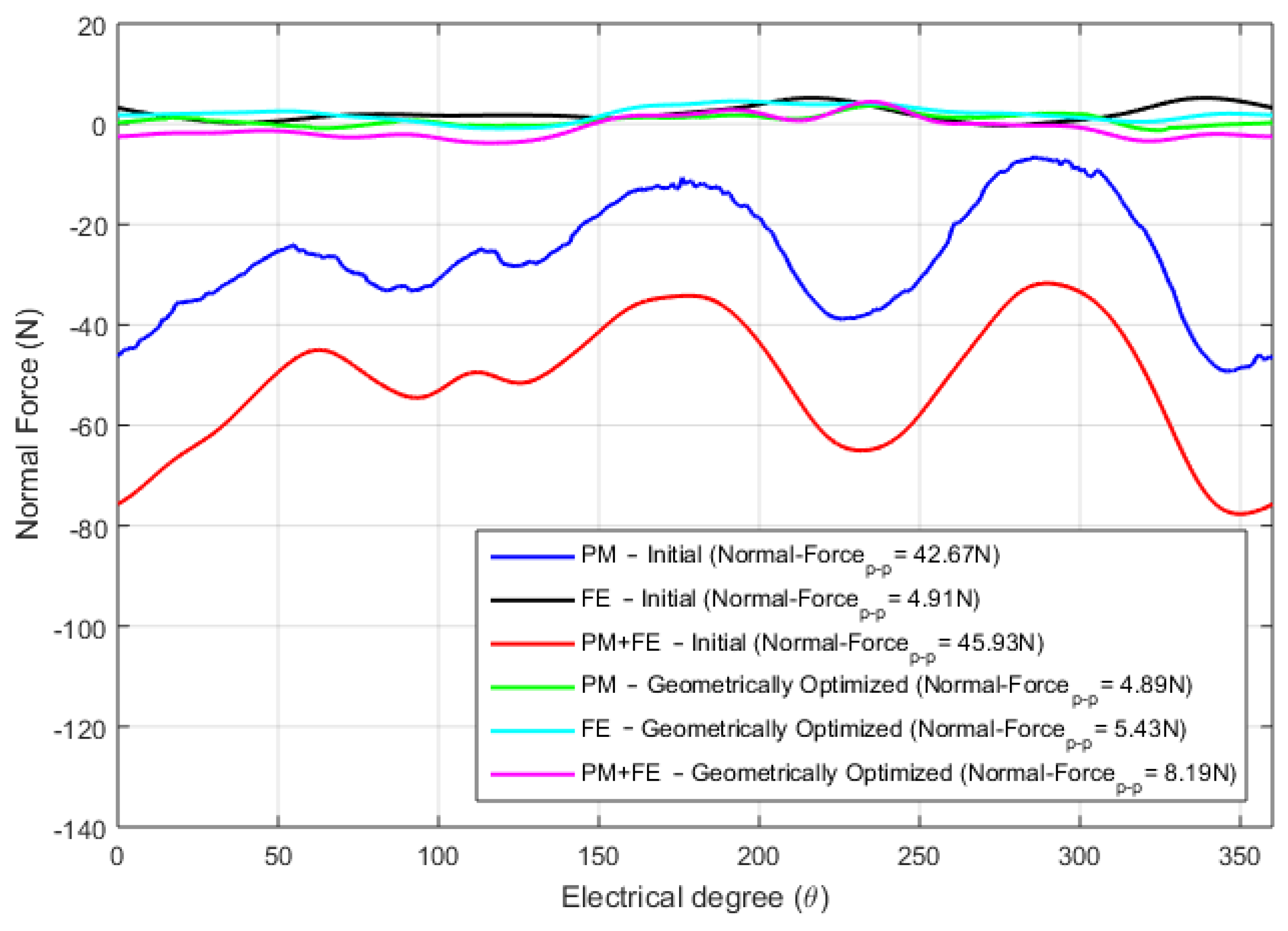
Normal force waveforms of the initial and geometrically optimized DSSSHELFSMs are compared in Figure 23. The double-sided design provides an advantage of a negligible normal force profile. The normal force profile is further improved during the optimization process. Its peak-to-peak value is reduced from 42.67 N to 4.89 N under only PM excitation and from 45.93 N to 8.19 N under hybrid excitation. However, the magnitude of the peak-to-peak normal force shows an insignificant increment from 4.91 N to 5.43 N in the case of FE-only excitation.
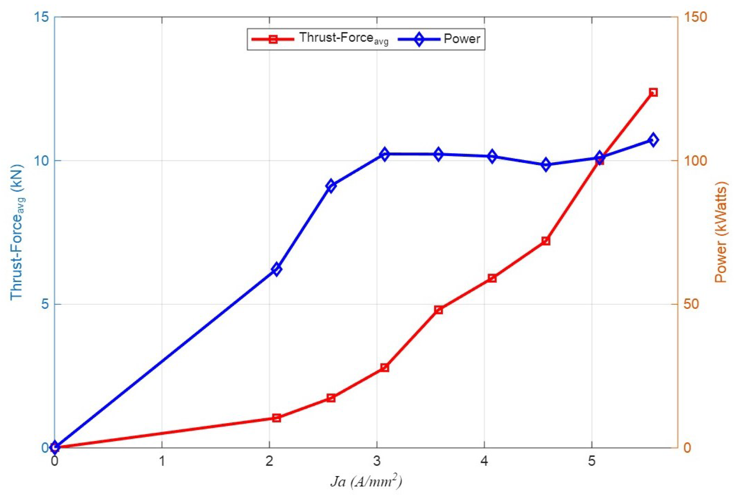
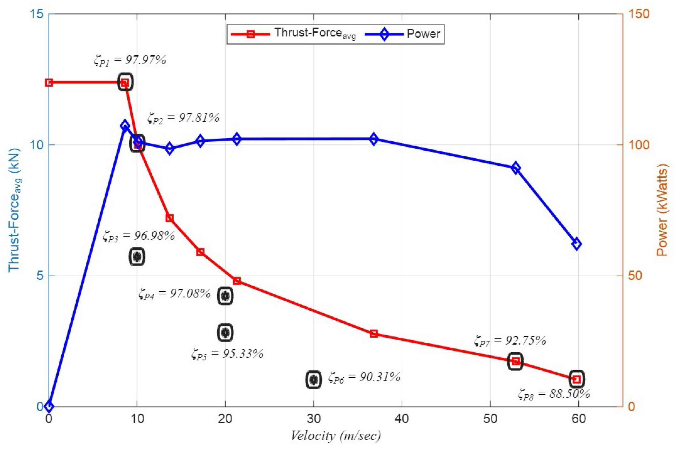
Figure 24 presents the thrust force and power as functions of the armature current density for the optimized DSSSHELFSM. Additionally, Figure 25 illustrates the thrust force and the characteristics of power versus velocity, together with the corresponding efficiency at eight selected points on the thrust force–velocity curve for the optimized machine.

5. Hardware Validation

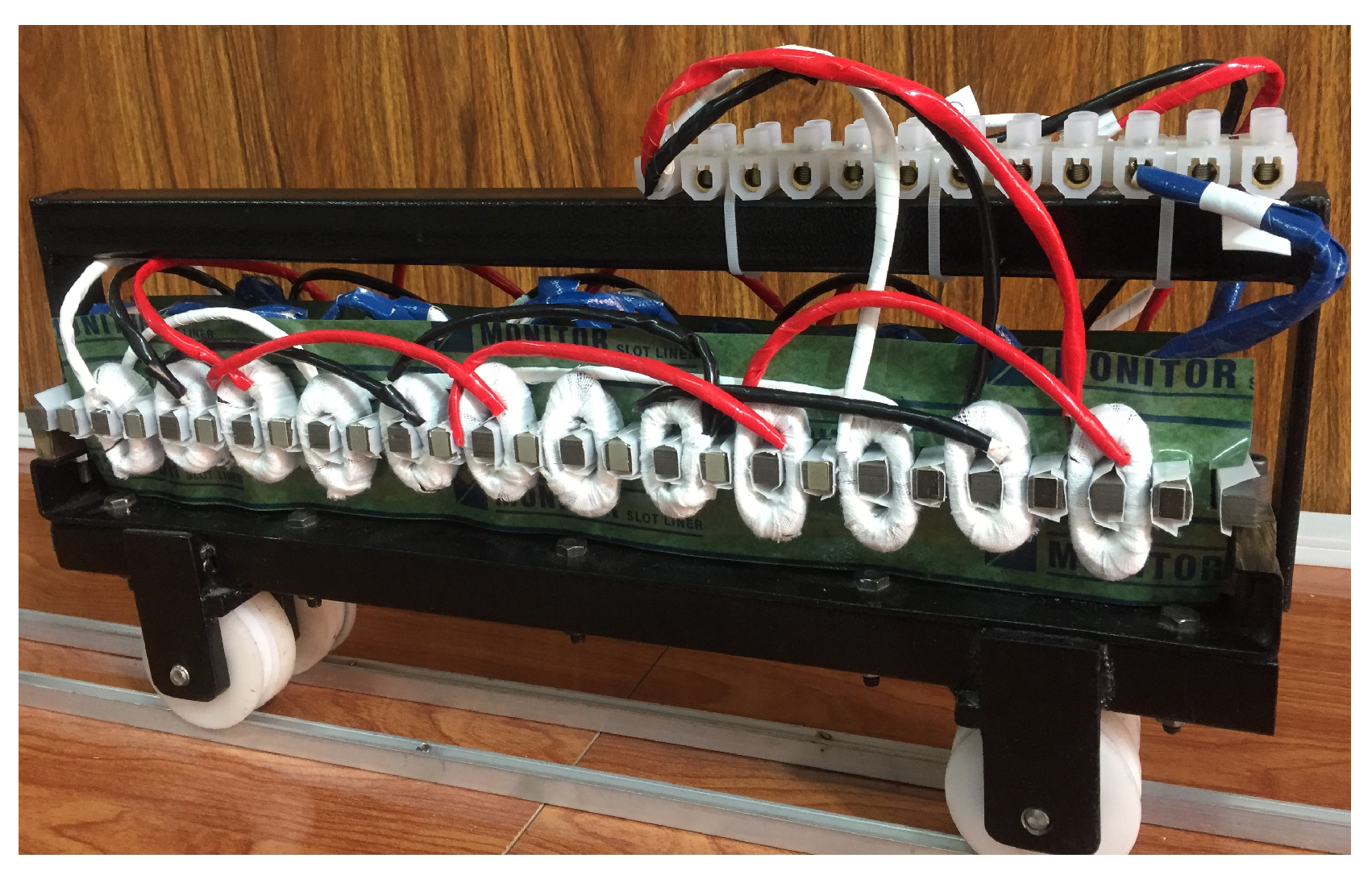
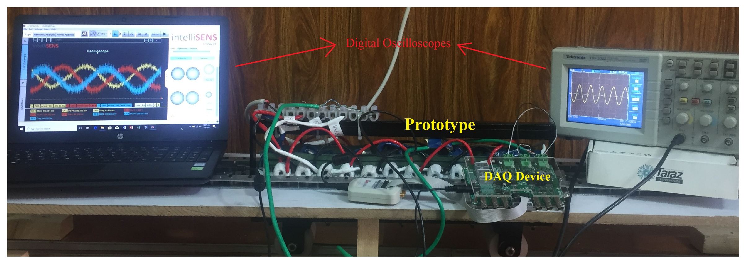
This section presents the full-scale prototype test bed of the optimized DSSSHELFSM. The primary and secondary cores were assembled using twenty-nine silicon steel sheets, each 0.35 mm thick, resulting in a total stack length of 10 mm. PMs were embedded in the mover core, and FECs and AW slots were subsequently wound to evaluate machine performance. Class B insulation sheets were applied to insulate the windings and core (Figure 26 and Figure 27). No-load B-EMF and detent force were experimentally validated against the corresponding FEA results.The resistance and inductance of the FECs and AWs (per phase) were measured. The FEC exhibited a resistance of 2.1 ohms and an inductance of 7.46 mH, while the center-phase AW showed a resistance of 0.7 ohms and an inductance of 0.996 mH.
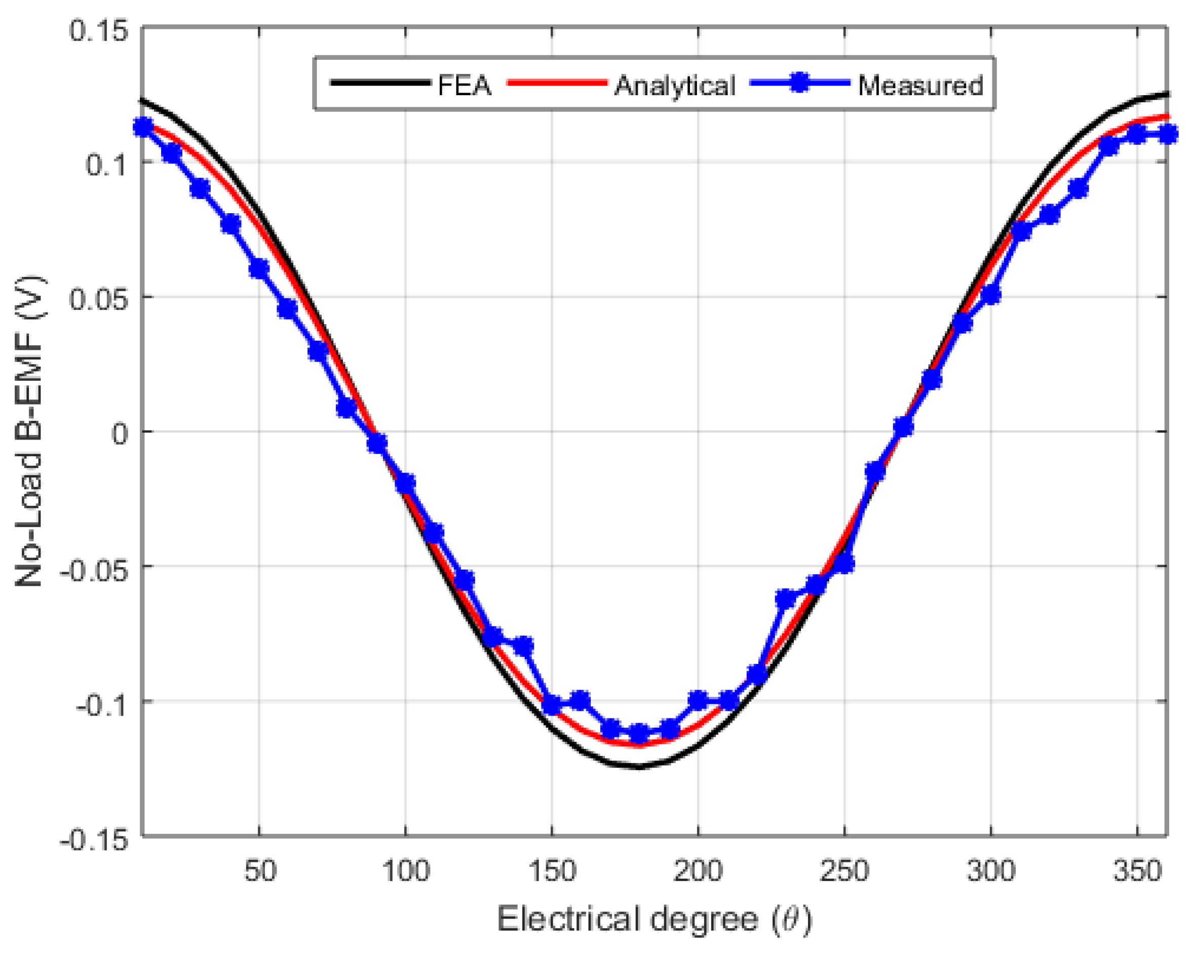
The proposed DSSSHELFSM was experimentally evaluated under hybrid excitation, in which both the permanent magnets and a 5A DC current supplied the FECs. Under no-load conditions, the machine was driven by a servo motor at a rated speed of 1.5 m/s, producing an induced voltage frequency of 50Hz, and the data were recorded using an intelliSENS DAQ system. The FEA and experimental back-EMF results for the central phase are shown in Figure 28. The experimental waveform exhibits good agreement with the corresponding FEA results, with slight differences mainly caused by manufacturing tolerances and assembly inaccuracies.
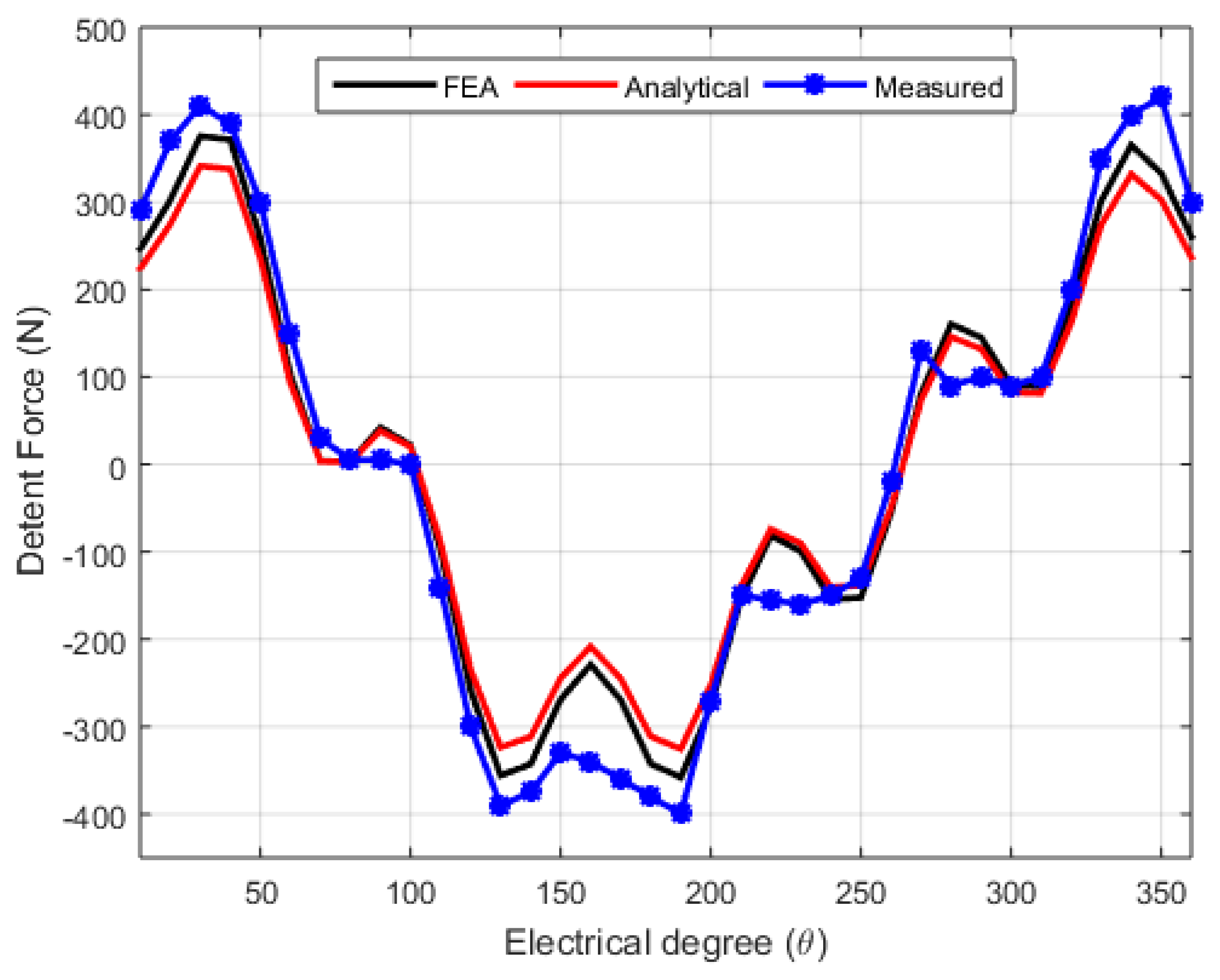
The detent force characteristics of the proposed DSSSHELFSM, obtained through FEA, were further validated using experimental measurements. An electrical resistance strain sensor was used to record the machine’s detent force. Since the average force at constant speed corresponds to the friction force, the actual detent force was calculated by removing the friction component from the measured no-load force. The comparison between the simulated and experimental detent force results, as illustrated in Figure 29, demonstrates close agreement. The small discrepancies observed are mainly due to non-uniform friction in the guide rails and noise in the measurement system.

6. Discussion

The proposed HELFSM provides several important benefits: (a) removal of the need for an MCS because of its linear structure, (b) reduction of excessive normal forces by employing a double-sided arrangement, (c) lowered secondary material consumption and shorter low-reluctance flux paths achieved through a segmented secondary configuration, (d) reduced dependence on rare-earth permanent magnet materials, leading to lower production costs, (e) elimination of PM losses and demagnetization issues, (f) the ability to control air-gap magnetic field density, and (g) improvement of thrust force density through hybrid excitation using both PMs and FECs. Moreover, unequal primary tooth widths are introduced to form low-reluctance paths in regions with high flux identified in preliminary simulations, while four auxiliary teeth are added to improve magnetic circuit balance and minimize end effects. The complementary winding arrangement and the combined series–parallel magnetic circuit further improve flux linkage symmetry, thereby reducing TFRR.
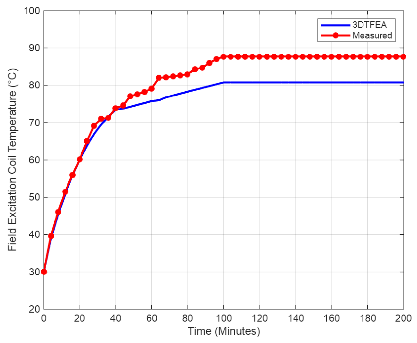
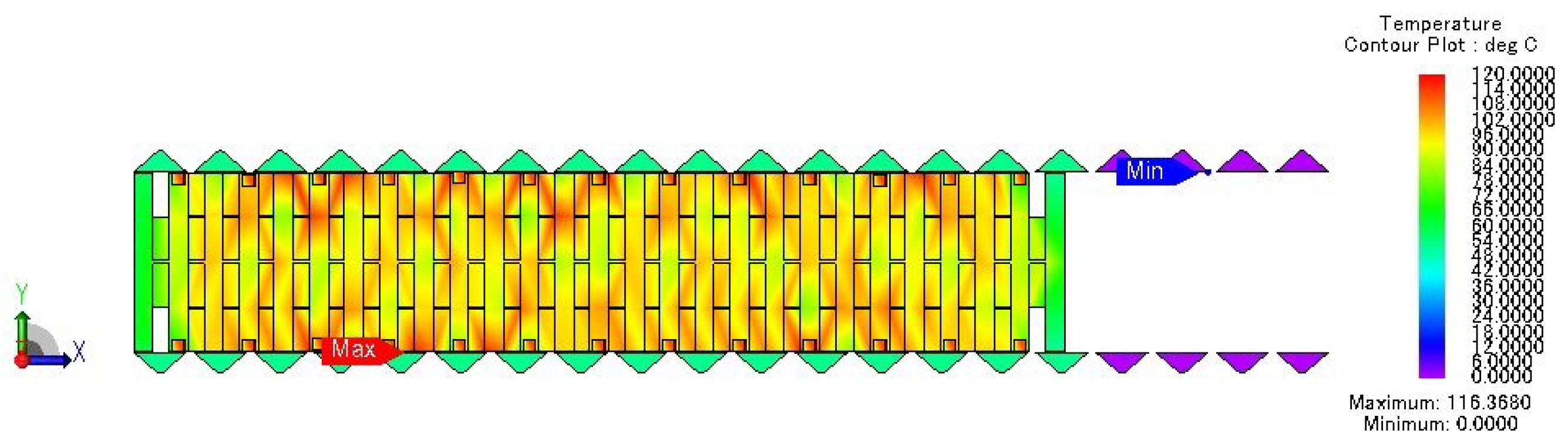
Thermal analysis of the proposed machine under the worst-case scenario (locked mover condition) was done using JMAG 3-D Thermal FE Analysis (3DTFEA) (Figure 30) and corresponding experimental results were obtained using a Fluke VT04 Visual IR Thermometer (Fluke Corporation, Everett, WA, USA). Thermal resistances due to conduction, convection, and radiation were calculated and considered according to the geometry of the proposed machine.
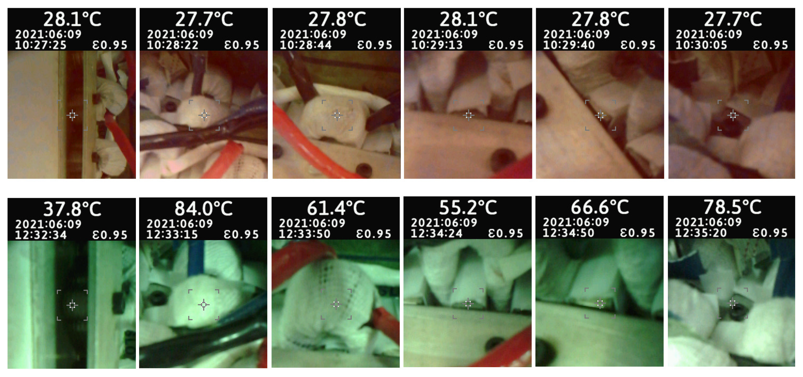
A 100% duty cycle with locked-mover conditions was investigated with continuous monitoring of machine parts’ temperature levels after a specified interval of 4 min. The purpose of this test was to define the continuous duty cycle operation time at which the machine approaches a steady-state temperature level, and also the hottest parts of the machine. All of the machine’s parts monitored using the IR thermometer are shown in Figure 31. A comparison of results for the hottest part (FEC winding) between 3DTFEA and the measured results is done in Figure 32.

7. Conclusions

Two novel designs for HELFSMs, termed as the Dual-Mover Segmented Secondary Hybrid Excited Linear Flux Switching Machine (DMSSHELFSM) and Dual-Stator Segmented Secondary Hybrid Excited Linear Flux Switching Machine (DSSSHELFSM), were investigated and compared for long stroke application, such as in ropeless vertical elevator systems. Detailed analysis revealed that the proposed DSSSHELFSM shows better electromagnetic performance in terms of no-load peak-to-peak flux linkage and average thrust force. Under hybrid excitation, DMSSHELFSM shows a no-load peak-to-peak flux linkage of 4.17 mWb with a THD of 12.54%, whereas DSSSHELFSM’s no-load peak-to-peak flux linkage is 8.10 mWb with a THD of 4.76%. The detent force of DMSSHELFSM is 2808.57 N and that of DSSSHELFSM is 2338.35 N. Average thrust force is an important KPI and plays an important role in selecting the best machine for a specified application. The average thrust forces of DMSSHELFSM and DSSSHELFSM were recorded as 5202.08 N and 7581.32 N. TFRR of the prior machine is 24.85%, and that of the latter one is 30.71%. Normal force profiles were also compared, recorded as 15.89 N for DMSSHELFSM and 45.93 N for DSSSHELFSM. Hence, DSSSHELFSM was considered as the best candidate for aforementioned target application.
The proposed DSSSHELFSM was optimized using the SVGBDO technique to further improve its performance. During the optimization, an average thrust force of 10 kN and a TFRR below 10% were set as the main constraints. The mover was optimized to enhance the average thrust force, while the stator was optimized to minimize TFRR. The results confirm that the peak-to-peak flux linkage increased from 8.10 mWb to 10.90 mWb and its THD decreased from 4.76% to 1.17%. The peak-to-peak detent force was reduced from 2338.35 N to 1028.83 N. Furthermore, the average thrust force improved from 7581.32 N to 10,111.13 N, while TFRR decreased from 30.71% to 9.15%. The normal force was also significantly reduced, from 45.93 N to 8.19 N. In addition, the thrust force per unit of power versus armature current density, thrust force per unit of power versus velocity characteristics, and efficiency at eight operating points on the thrust force–velocity curve were evaluated.
Finally, a full-scale prototype with a stack length of 10mm was manufactured and tested. The no-load B-EMF waveform and detent force profile for one electrical cycle at rated speed of 1.5 m/s were experimentally validated against corresponding FEA results. A good agreement between the simulated and experimental results was obtained. However, minor deviations were observed, mainly due to non-uniform friction in the guide rails and noise in the measurement system.

Author Contributions

Conceptualization, N.U. and F.K.; methodology, M.S.; software, N.U.; validation, N.U., M.S. and F.K.; formal analysis, F.K.; investigation, M.S.; resources, F.K.; data curation, M.S.; writing—original draft preparation, N.U.; writing—review and editing, M.S.; visualization, F.K.; supervision, F.K.; project administration, F.K.; funding acquisition, F.K. All authors have read and agreed to the published version of the manuscript.

Funding

This research was funded by the Higher Education Commission, Pakistan, grant number HEC-TDF-067.

Informed Consent Statement

Not applicable.

Data Availability Statement

The datasets presented in this article are not readily available because the data are part of an ongoing study.

Conflicts of Interest

The authors declare no conflicts of interest.

Abbreviations

The following abbreviations are used in this manuscript:
HELFSMHybrid-Excited Linear Flux Switching Machine
DMSSHELFSMDual-Mover Segmented Secondary Hybrid Excited Linear Flux Switching Machine
DSSSHELFSMDual-Stator Segmented Secondary Hybrid Excited Linear Flux Switching Machine
SVGBDOSingle-Variable Geometry-Based Deterministic Optimization
TFRRThrust Force Ripple Ratio
LFSMLinear Flux Switching Machine
LPMSMLinear Permanent Magnet Synchronous Machine
LIMLinear Induction Machine
LSRMLinear Switched Reluctance Machine
LDCMLinear Direct Current Machine

References

  1. Hellinger, R.; Mnich, P. Linear motor-powered transportation: History, present status, and future outlook. Proc. IEEE 2009, 97, 1892–1900. [Google Scholar] [CrossRef] [Scilit]
  2. Ullah, N.; Basit, A.; Khan, F.; Ullah, W.; Shahzad, M.; Zahid, A. Enhancing capabilities of double-sided linear flux switching permanent magnet machines. Energies 2018, 11, 2781. [Google Scholar]
  3. Fan, H.; Chau, K.T.; Liu, C.; Cao, L.; Ching, T.W. Quantitative comparison of novel dual-PM linear motors for ropeless elevator system. IEEE Trans. Magn. 2018, 54, 8106506. [Google Scholar] [CrossRef] [Scilit]
  4. Bowers, B. Sir Charles Wheatstone FRS: 1802–1875, 2nd ed.; No. 29; The Institution of Electrical Engineers: London, UK, 2001; pp. 1–256. [Google Scholar]
  5. Cao, R.; Cheng, M.; Mi, C.; Hua, W.; Wang, X.; Zhao, W. Modeling of a complementary and modular linear flux-switching permanent magnet motor for urban rail transit applications. IEEE Trans. Energy Convers. 2012, 27, 489–497. [Google Scholar] [CrossRef] [Scilit]
  6. Higuchi, T.; Nonaka, S.; Ando, M. On the design of high-efficiency linear induction motors for linear metro. Electr. Eng. Jpn. 2001, 137, 36–43. [Google Scholar]
  7. Yoon, S.B.; Hur, J.; Hyun, D.S. A method of optimal design of single-sided linear induction motor for transit. IEEE Trans. Magn. 1997, 33, 4215–4217. [Google Scholar] [CrossRef] [Scilit]
  8. Tosifian, M.H.; Nazarzadeh, J. A detailed model of disk type linear induction machines. Int. Trans. Electr. Energy Syst. 2015, 25, 1736–1747. [Google Scholar]
  9. Chau, K.T.; Chan, C.C.; Liu, C. Overview of permanent-magnet brushless drives for electric and hybrid electric vehicles. IEEE Trans. Ind. Electron. 2008, 55, 2246–2257. [Google Scholar] [CrossRef] [Scilit]
  10. Yasa, Y.; Elamin, M.; Sozer, Y.; Kutz, J.; Tylenda, J.S.; Wright, R.L. Acoustic noise mitigation for high pole count switched reluctance machines through skewing method with multiphysics FEA simulations. In Proceedings of the IEEE Energy Conversion Congress and Exposition (ECCE), Cincinnati, OH, USA, 1–5 October 2017; pp. 738–744. [Google Scholar]
  11. Ullah, N.; Khan, F.; Basit, A.; Ullah, W.; Shahzad, M.; Ahmad, T.; Khalid, U. Performance comparison and optimisation of dual mover linear permanent magnet flux switching machine. IET Electr. Power Appl. 2019, 13, 984–995. [Google Scholar] [CrossRef] [Scilit]
  12. Zhu, Z.-Q.; Chen, J. Advanced flux-switching permanent magnet brushless machines. IEEE Trans. Magn. 2010, 46, 1447–1453. [Google Scholar] [CrossRef] [Scilit]
  13. Wang, C.-F.; Shen, J.-X.; Wang, Y.; Wang, L.-L.; Jin, M.-J. A new method for reduction of detent force in permanent magnet flux-switching linear motors. IEEE Trans. Magn. 2009, 45, 2843–2846. [Google Scholar] [CrossRef] [Scilit]
  14. Hwang, C.-C.; Li, P.-L.; Liu, C.-T. Design and analysis of a novel hybrid excited linear flux switching permanent magnet motor. IEEE Trans. Magn. 2012, 48, 2969–2972. [Google Scholar] [CrossRef] [Scilit]
  15. Cao, R.; Huang, W.; Cheng, M. A new modular and complementary double-sided linear flux-switching permanent magnet motor with yokeless secondary. In Proceedings of the 17th International Conference on Electrical Machines and Systems (ICEMS), Hangzhou, China, 22–25 October 2014; pp. 3648–3652. [Google Scholar]
  16. Xiao, F.; Du, Y.; Sun, Y.; Zhu, H.; Zhao, W.; Li, W.; Ching, T.W.; Qiu, C. A novel double-sided flux-switching permanent magnet linear motor. J. Appl. Phys. 2015, 117, 17B530. [Google Scholar]
  17. Hao, W.; Wang, Y.; Deng, Z. Study of two kinds of double-sided yokeless linear flux-switching permanent magnet machines. In Proceedings of the IEEE Vehicle Power and Propulsion Conference (VPPC), Hangzhou, China, 17–20 October 2016; pp. 1–6. [Google Scholar]
  18. Cao, R.; Su, E. New Double-Sided Wound Field Flux-Switching Linear Motor with Non-Overlapping Winding. In Proceedings of the IEEE International Electric Machines & Drives Conference (IEMDC), San Diego, CA, USA, 12–15 May 2019; pp. 1746–1751. [Google Scholar]
  19. Gandhi, A.; Parsa, L. Hybrid flux-switching linear machine with fault-tolerant capability. In Proceedings of the IEEE International Electric Machines & Drives Conference (IEMDC), Coeur d’Alene, ID, USA, 10–13 May 2015; pp. 715–720. [Google Scholar]
  20. Zeng, Z.; Lu, Q. Investigation of novel partitioned-primary hybrid-excited flux-switching linear machines. IEEE Trans. Ind. Electron. 2017, 65, 9804–9813. [Google Scholar] [CrossRef]
  21. Khan, F.; Sulaiman, E.; Ahmad, M.Z. A novel wound field flux switching machine with salient pole rotor and nonoverlapping windings. Turk. J. Electr. Eng. Comput. Sci. 2017, 25, 950–964. [Google Scholar] [CrossRef] [Scilit]
  22. Zeng, Z.; Lu, Q. A Novel Hybrid-Excitation Switched-Flux Linear Machine with Partitioned-Excitations. IEEE Trans. Magn. 2019, 55, 7502204. [Google Scholar] [CrossRef] [Scilit]
  23. Cao, R.; Jin, Y.; Zhang, Z.; Cheng, M. A new double-sided linear flux-switching permanent magnet motor with yokeless mover for electromagnetic launch system. IEEE Trans. Energy Convers. 2018, 34, 680–690. [Google Scholar] [CrossRef] [Scilit]
  24. Abdollahi, S.E.; Vaez-Zadeh, S. Back EMF analysis of a novel linear flux switching motor with segmented secondary. IEEE Trans. Magn. 2014, 50, 8200809. [Google Scholar] [CrossRef] [Scilit]
  25. Wang, D.; Du, X.; Wang, X. Force ripple reduction of a linear flux switching motor with segmented secondary. In Proceedings of the 20th International Conference on Electrical Machines and Systems (ICEMS), Sydney, NSW, Australia, 11–14 August 2017; pp. 1–5. [Google Scholar]
  26. Hao, W.; Wang, Y. Analysis of double-sided sandwiched linear flux-switching permanent-magnet machines with staggered stator teeth for urban rail transit. IET Electr. Syst. Transp. 2018, 8, 175–181. [Google Scholar] [CrossRef] [Scilit]
  27. Cao, R.; Jin, Y.; Zhang, Y.; Cheng, M. A new double-sided HTS flux-switching linear motor with series magnet circuit. IEEE Trans. Appl. Supercond. 2016, 26, 5207405. [Google Scholar] [CrossRef] [Scilit]
  28. Lu, M.; Cao, R. Comparative Investigation of High Temperature Superconducting Linear Flux-Switching Motor and High Temperature Superconducting Linear Switched Reluctance Motor for Urban Railway Transit. IEEE Trans. Appl. Supercond. 2021, 31, 3600605. [Google Scholar] [CrossRef] [Scilit]
  29. Huang, L.; Yu, H.; Hu, M.; Liu, H. Study on a long primary flux-switching permanent magnet linear motor for electromagnetic launch systems. IEEE Trans. Plasma Sci. 2013, 41, 1138–1144. [Google Scholar] [CrossRef] [Scilit]
  30. Cao, R.; Jin, Y.; Lu, M.; Zhang, Z. Quantitative comparison of linear flux-switching permanent magnet motor with linear induction motor for electromagnetic launch system. IEEE Trans. Ind. Electron. 2018, 65, 7569–7578. [Google Scholar] [CrossRef] [Scilit]
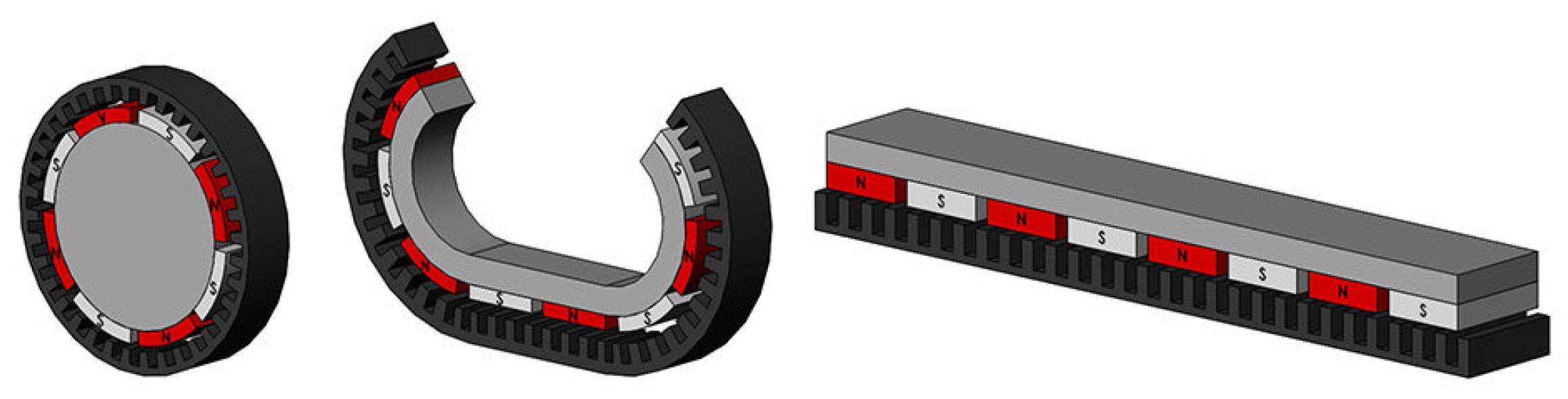
Figure 1. Splitting and unrolling process.
Machines 14 00374 g001
Figure 2. Classification of LFSMs.
Machines 14 00374 g002
Figure 3. Existing setup versus proposed solution of ropeless elevator system; (a) Existing setup; (b) Proposed solution.
Machines 14 00374 g003
Figure 4. Proposed SSHELFSMs: (a) DMSSHELFSM. (b) DSSSHELFSM.
Machines 14 00374 g004
Figure 5. Design variables of proposed SSHELFSMs: (a) DMSSHELFSM. (b) DSSSHELFSM.
Machines 14 00374 g005
Figure 6. No-load flux linkage of proposed SSHELFSMs: (a) Waveform comparison. (b) Corresponding frequency spectrum.
Machines 14 00374 g006
Figure 7. Detent force profiles of DMSSHELFSM and DSSSHELFSM.
Machines 14 00374 g007
Figure 8. Thrust force profiles of DMSSHELFSM and DSSSHELFSM.
Machines 14 00374 g008
Figure 9. Normal force profiles of DMSSHELFSM and DSSSHELFSM.
Machines 14 00374 g009
Figure 10. Three dimensional structure of proposed DSSSHELFSM.
Machines 14 00374 g010
Figure 11. SVGBDO approach methodology.
Machines 14 00374 g011
Figure 12. Split ratio optimization.
Machines 14 00374 g012
Figure 13. Slot area dimension optimization.
Machines 14 00374 g013
Figure 14. PM dimension optimization.
Machines 14 00374 g014
Figure 15. Flux distribution under same tooth width.
Machines 14 00374 g015
Figure 16. Unequal primary tooth width optimization.
Machines 14 00374 g016
Figure 17. Flux distribution under unequal tooth width.
Machines 14 00374 g017
Figure 18. Stator segment tip width optimization.
Machines 14 00374 g018
Figure 19. Stator segment base width optimization.
Machines 14 00374 g019
Figure 20. No-load flux linkage of DSSSHELFSMs: (a) Waveform comparison. (b) Corresponding frequency spectrum.
Machines 14 00374 g020
Figure 21. Comparison of detent force profile.
Machines 14 00374 g021
Figure 22. Comparison of thrust force profile.
Machines 14 00374 g022
Figure 23. Comparison of normal force profile.
Machines 14 00374 g023
Figure 24. Thrust force and power versus armature current density.
Machines 14 00374 g024
Figure 25. Thrust force and power versus velocity.
Machines 14 00374 g025
Figure 26. DSSSHELFSM assembly.
Machines 14 00374 g026
Figure 27. Electromagnetic performance experimental test bench.
Machines 14 00374 g027
Figure 28. Experimental validation of no-load B-EMF.
Machines 14 00374 g028
Figure 29. Experimental validation of detent force.
Machines 14 00374 g029
Figure 30. Spatial temperature distribution in degree Celsius.
Machines 14 00374 g030
Figure 31. Fluke VT04 Visual IR Thermometer results.
Machines 14 00374 g031
Figure 32. Comparison of simulated and measured FEC temperature levels.
Machines 14 00374 g032
Table 1. Numerical values of geometric parameter variables for both the DMSSHELFSM and DSSSHELFSM configurations.
Parameter (Unit)ValueParameter (Unit)Value
τ m (mm)35 τ s (mm)30
h m (mm)85 h s (mm)25
w D C t (mm)7.5 w A C t (mm)7.5
w s l o t (mm)10 h s l o t (mm)17.5
h y (mm)15 w P M (mm)5
h P M (mm)5 V P M (g)45.5
w s s t (mm)24 w s s b (mm)12
h s s (mm)12.5g (mm)2
L (mm)10v (m/s)1.5
N A C a n d D C 40 J A C a n d D C (A/mm2)4.57 and 4.52
Disclaimer/Publisher’s Note: The statements, opinions and data contained in all publications are solely those of the individual author(s) and contributor(s) and not of MDPI and/or the editor(s). MDPI and/or the editor(s) disclaim responsibility for any injury to people or property resulting from any ideas, methods, instructions or products referred to in the content.