Article

Hybrid ANN-Based MPPT Strategy for Boost Converter PV Systems Under Rapid Irradiance Variations

1
Electrical and Computer Engineering Department, College of Engineering, Sultan Qaboos University, Muscat 123, Oman
2
Electrical Engineering Department, College of Engineering, Damanhour University, Damanhour 22514, Egypt
*
Author to whom correspondence should be addressed.
Machines 2026, 14(6), 659; https://doi.org/10.3390/machines14060659
Submission received: 19 April 2026 / Revised: 24 May 2026 / Accepted: 29 May 2026 / Published: 6 June 2026

Abstract

Maximum power point tracking (MPPT) is a critical function for maximizing energy extraction in photovoltaic (PV) systems. Due to the inherently dynamic nature of the maximum power point under varying irradiance conditions, achieving fast convergence, low steady-state oscillations, and high tracking efficiency remains a challenging research problem. This paper proposes a hybrid ANN-based MPPT strategy for photovoltaic systems operating under rapidly changing environmental conditions. The proposed approach integrates a rule-based operating-condition estimation stage with a recurrent ANN-based control stage, enabling adaptive duty-cycle generation using measured PV voltage and current signals. Unlike conventional MPPT techniques, the proposed method utilizes operating-region estimation together with an extended ANN input feature vector and a recurrent backpropagation neural network to improve dynamic tracking performance under abrupt irradiance variations. In addition, a composite loss function is adopted to enhance tracking accuracy, guidance consistency, and control smoothness. The ANN is initially trained offline and subsequently refined online using lightweight incremental adaptation to maintain effective operation with a low computational burden. The proposed MPPT strategy is evaluated against P&O, FLC, and SMC. Simulation results demonstrate improved tracking performance, faster dynamic response, and reduced steady-state oscillations under abrupt irradiance variations.

1. Introduction

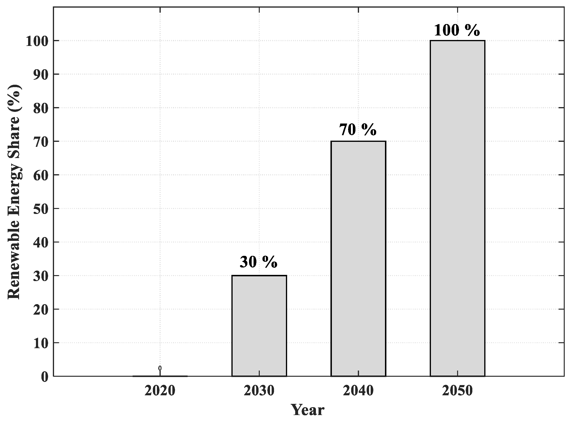
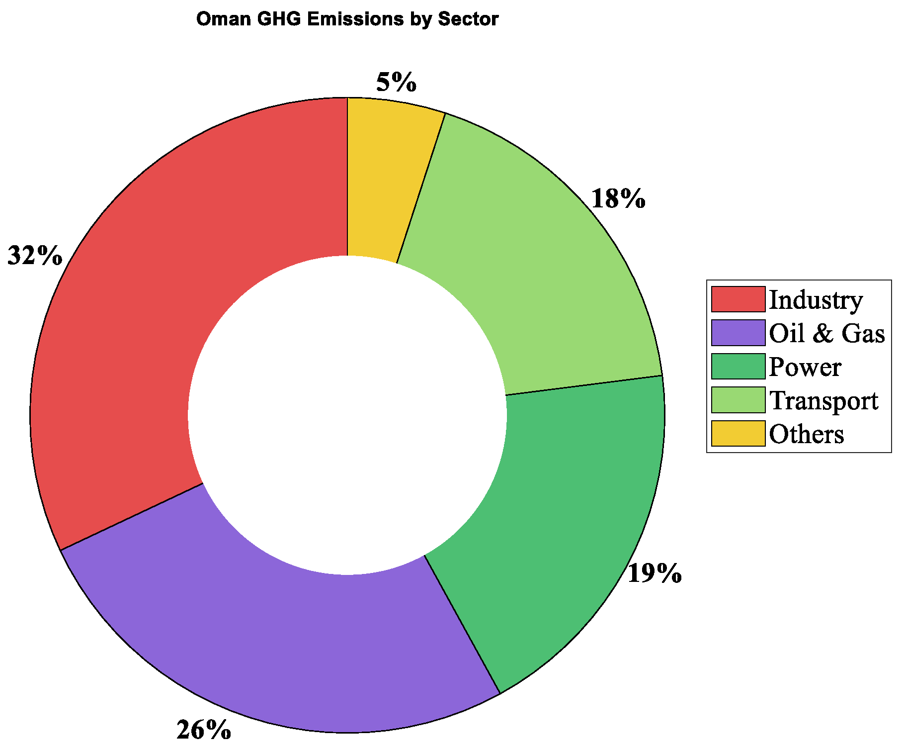
Under Oman Vision 2040 [1], the Sultanate of Oman is advancing toward a digitally integrated economy, supported by targeted national initiatives such as the “Tahawul” program [2]. These efforts are further strengthened by continued investments in digital infrastructure and the growing adoption of emerging technologies, including artificial intelligence and the Internet of Things (IoT). In this context, the deployment of smart infrastructure serves as a key enabler for achieving more efficient, resilient, and adaptive systems [3]. The electricity sector plays a central role in this transition due to its strong connection to both economic development and environmental sustainability. As Oman expands its solar and wind energy projects, alongside its increasing interest in green hydrogen, the sector is undergoing a significant transformation. National projections indicate that renewable energy will account for at least 30% of total energy by 2030 [4,5], rising to 70% by 2040 [6,7], and reaching 100% by 2050, as illustrated in Figure 1, in alignment with the national objective of achieving net-zero emissions in the power sector [8,9]. Currently, electricity generation remains a major source of greenhouse gas (GHG) emissions in Oman, contributing approximately 19% of the national total, as shown in Figure 2. This transition is supported by favorable conditions, including abundant solar and wind resources and the availability of land for large-scale deployments. Together, these factors position Oman to accelerate its renewable energy transition and strengthen its contribution to the global decarbonization effort.
Furthermore, electricity demand has surged over the past decade, increasing by approximately 240% as a result of population growth and rapid industrialization [5]. This sustained rise has directly driven investment in clean energy technologies and accelerated the development of enabling infrastructure for their large-scale integration. At the national level, this transition is already materializing through major utility-scale initiatives, including three large-scale solar power plants. These developments contribute directly to Oman’s net-zero trajectory while aligning with its national renewable energy targets. Building on this momentum, the government is expected to procure additional utility-scale projects by 2027, underscoring a sustained and strategic commitment to expanding clean energy capacity. However, one of the main characteristics of PV systems is that the maximum power point (MPP) varies continuously with environmental conditions, particularly solar irradiance and temperature. While the terminal voltage is only slightly affected by variations in irradiance, the output current increases significantly as solar irradiance rises, leading to considerable changes in the output power [10]. In contrast, temperature variations mainly affect the output voltage, whereas their influence on the output current remains relatively limited [10]. As a result, continuously changing environmental conditions make it difficult to maintain operation at the maximum power point. Therefore, maximizing energy extraction in PV systems under sustained changes in environmental conditions represents a significant challenge for engineers.
In recent years, artificial intelligence (AI) techniques have become increasingly integral to modern engineering systems, with rapidly expanding applications in power electronics and renewable energy technologies. In particular, AI-based approaches have been widely adopted for inverter efficiency optimization, load frequency control in renewable energy-dominated power systems, and advanced estimation and control of electric motor drives [11,12]. In this context, ref. [11] proposes a machine-learning-based fault detection framework using the K-nearest neighbor (KNN) algorithm for multicellular photovoltaic (PV) converters, thereby enhancing operational reliability under fault conditions. Similarly, ref. [12] develops a fuzzy logic-based maximum power point tracking (MPPT) strategy that demonstrates improved tracking efficiency and superior dynamic response compared to the conventional perturb and observe (P&O) method.
Solar energy continues to be recognized as one of the most promising and scalable renewable energy sources, particularly for small- to medium-scale applications. This growing interest is largely driven by declining PV costs and continuous improvements in conversion efficiency [13]. PV modules directly convert solar irradiance into electrical energy [14], enabling versatile deployment in both off-grid remote areas and conventional grid-connected systems. As a result, PV systems have emerged as a reliable solution for isolated communities, offering enhanced energy accessibility and partial energy autonomy [15].
Improving the efficiency of PV energy conversion systems relies heavily on the design of effective control strategies, particularly at the power electronic interface level. In this regard, the DC–DC converter plays a critical role as the intermediate stage between the PV array and the load, where proper control is essential to ensure maximum power extraction [16,17]. To address this challenge, a wide range of MPPT techniques has been developed, including classical algorithms such as P&O and incremental conductance (INC), nonlinear control methods such as backstepping and sliding mode control, as well as artificial intelligence-based approaches, including fuzzy logic systems and artificial neural networks.
Among intelligent control strategies, fuzzy logic control (FLC) has gained significant attention over the past two decades due to its robustness in handling nonlinear and uncertain systems without requiring an explicit mathematical model [18]. This model-free characteristic makes FLC particularly attractive for practical applications where system dynamics are complex, time-varying, or difficult to model accurately.
In parallel, sliding mode control (SMC) has emerged as a powerful nonlinear control technique widely employed in power electronics and variable-structure systems. Recently, it has been successfully applied to both grid-connected and stand-alone PV systems, including renewable-based applications such as solar water pumping [14,19]. The core principle of SMC is the definition of a sliding surface in the system state space, toward which system trajectories are driven using a discontinuous control law. Once the trajectory reaches this surface, it is constrained to remain on it, ensuring strong robustness against parameter variations and external disturbances [20]. In recent years, conventional SMC has been extended to more advanced nonlinear structures, including terminal sliding mode (TSM), non-singular terminal sliding mode (NTSM), and fast non-singular terminal sliding mode (FNTSM). These approaches have been developed to improve convergence speed, enhance tracking accuracy, suppress chattering, and increase robustness against parameter uncertainties and external disturbances in nonlinear systems. Among them, NTSM has attracted considerable attention because it maintains finite-time convergence while avoiding the singularity problems associated with conventional TSM schemes. Recent studies have demonstrated the effectiveness of advanced SMC-based techniques in renewable energy applications, particularly in grid-connected inverters for microgrids and DC–DC converter systems, where fast dynamic response and robust operation under varying operating conditions are required [21,22,23]. These characteristics make SMC-based approaches well-suited for boost converter-based MPPT applications in photovoltaic systems.
Among classical MPPT techniques, the perturb and observe (P&O) method remains one of the most widely implemented approaches due to its simplicity and low computational burden. The method operates by continuously measuring PV output voltage and current [24,25], and perturbing the operating voltage via duty-cycle adjustment of the DC–DC converter. The resulting change in output power is then used to guide the system toward the maximum power operating point [26].
To maintain continuous operation at the MPP under rapidly changing environmental conditions, robust MPPT controllers are essential. These controllers dynamically adjust the operating point of the PV system in response to variations in temperature and solar irradiance, thereby enhancing energy harvesting efficiency and overall system performance. In this regard, artificial neural networks (ANNs) provide a promising solution. Inspired by biological neural systems, ANNs are capable of modeling complex nonlinear mappings and adaptive learning behavior, making them particularly suitable for real-time MPPT under highly dynamic environmental conditions [27].
Artificial neural networks (ANNs) are fundamentally built upon the concept of the artificial neuron, which was originally inspired by the structure and functionality of biological neurons. In general, the operation of a neural network is characterized by two main phases [28,29]:
  • Learning (training) phase: During this phase, the network iteratively adjusts the synaptic weights connecting neurons based on available input–output data, thereby minimizing the error between predicted and target outputs.
  • Execution (inference) phase: During this phase, the trained model is deployed to process unseen inputs and generate corresponding outputs for decision-making, estimation, or control purposes.
In previous studies investigating ANN-based control and energy management in PV systems with storage integration [30,31], the reported performance was often limited by noticeable oscillatory behavior in the output response. These oscillations degraded system stability and reduced overall control effectiveness, particularly under rapidly varying environmental conditions. Different studies summarized in Table 1 highlight a range of ANN-based techniques for MPPT in PV systems [29,32,33,34,35,36,37]. In general, ANN-driven approaches such as those reported in [29,35] employ irradiance and temperature data to estimate either the optimal MPP voltage or the corresponding control signal. These methods typically achieve high tracking accuracy and fast convergence, particularly when combined with advanced optimization or robust control strategies. However, their performance is often limited by the requirement for large, high-quality training datasets and the significant computational burden associated with offline training, which can reduce adaptability in real-time applications. In contrast, ANN-optimized and hybridized approaches, such as those in [33,37], integrate neural networks with metaheuristic optimization techniques, including genetic algorithms (GA), particle swarm optimization (PSO), and fuzzy logic controllers. These strategies generally provide improved tracking efficiency and enhanced performance under varying irradiance and temperature conditions. Nevertheless, these benefits are achieved at the expense of increased algorithmic complexity, higher computational cost, and more demanding implementation requirements. Adaptive and online learning-based methods, as presented in [32,36], introduce real-time parameter updating mechanisms to improve dynamic response and reduce dependence on fixed offline training. In particular, ref. [32] employs a neural identifier–controller structure with significant computational requirements, while ref. [36] introduces a lightweight single-neuron direct adaptive controller based on a rule. Notably, ref. [36] eliminates the need for irradiance and temperature sensors by relying solely on electrical measurements, thereby improving practical applicability. However, these adaptive schemes require careful tuning to ensure stable convergence and reliable operation under varying environmental conditions. Furthermore, ANN-augmented classical MPPT techniques, such as the approach in [34], enhance conventional perturb and observe (P&O) methods by incorporating neural estimation to improve transient response under rapidly changing irradiance. Despite this improvement, the overall control strategy still depends on the underlying P&O logic, which may limit optimal performance in certain operating scenarios.
The main contributions of this work can be summarized as follows:
  • A hybrid ANN-based MPPT framework is proposed by integrating a rule-based estimation stage with a recurrent ANN-based control stage to improve tracking performance under varying irradiance conditions.
  • A lightweight operating-region estimation mechanism based on the (ΔPpvVpv) characteristic is developed to generate an auxiliary duty-cycle guidance signal for the ANN-based controller.
  • An extended ANN input feature vector is introduced by combining measured PV variables with intermediate operating indicators and auxiliary guidance signals to provide a more informative representation of the system operating condition.
  • A recurrent backpropagation neural network architecture with self-feedback hidden-layer connections is employed to improve the dynamic tracking capability of the MPPT controller during irradiance transitions.
  • A modified ANN training objective is adopted to enhance tracking accuracy while reducing duty-cycle oscillations and improving steady-state stability.
  • The proposed controller combines offline ANN pretraining with lightweight online incremental adaptation to maintain effective operation under abrupt irradiance variations.
  • The effectiveness of the proposed MPPT strategy is validated through detailed MATLAB/Simulink 2023 simulations and comparative analysis with conventional MPPT techniques under abrupt irradiance variations.

2. Conventional MPPT Approaches and PV System Description

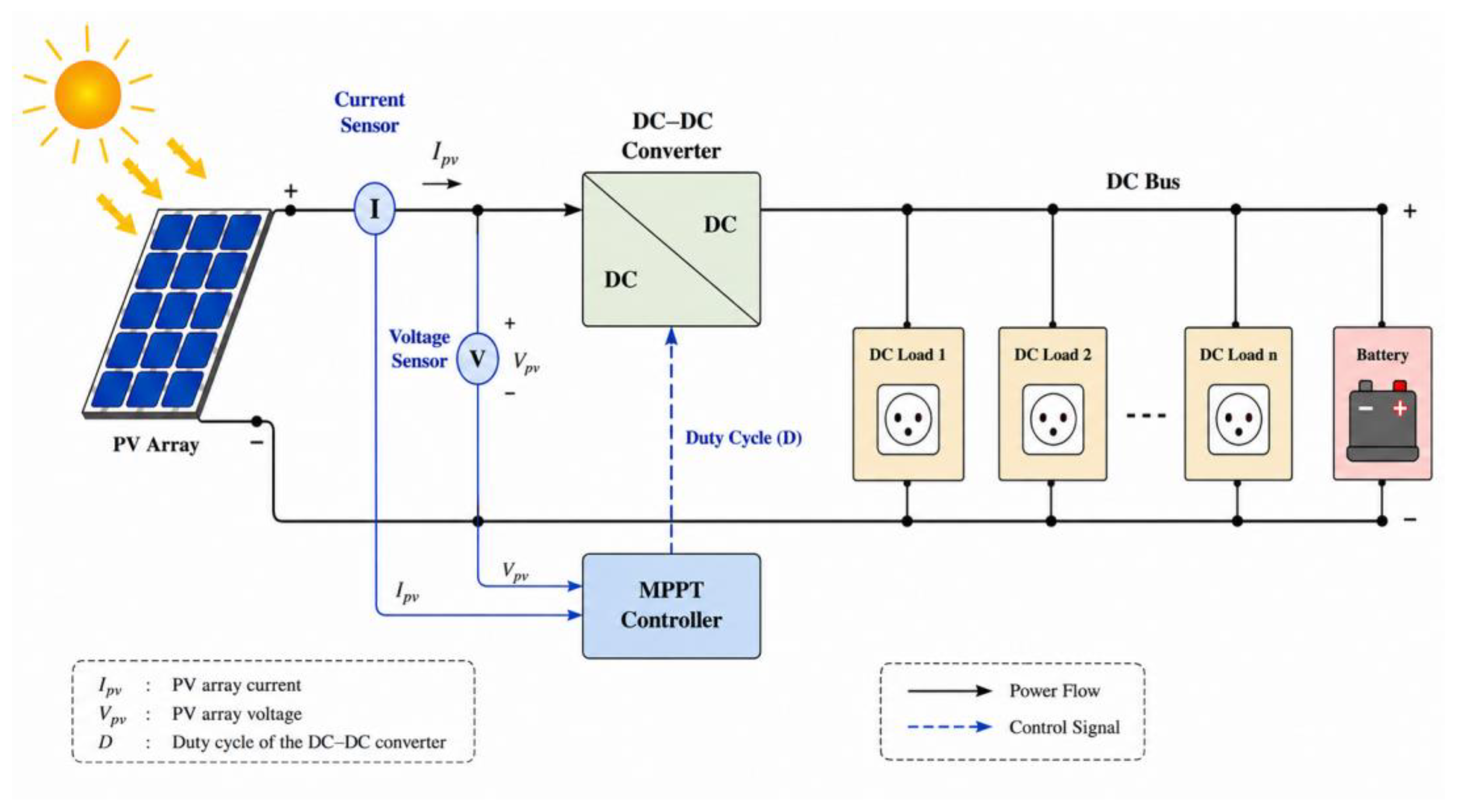
Prior to benchmarking the proposed system against conventional power supply architectures, it is essential to first establish a clear representation of the PV system configuration. A precise description of its architecture and constituent components provides the necessary foundation for understanding its operational behavior and enables a rigorous and meaningful comparison in subsequent analysis. The proposed PV system is composed of several tightly integrated subsystems, namely a PV generator, a battery energy storage unit, a DC/DC power converter, an MPPT controller, a supervision and control module, and the electrical load. Collectively, these components form a coordinated energy conversion and management framework, in which generation, regulation, storage, and consumption are dynamically balanced to ensure stable system operation. Specifically, the PV generator is responsible for harvesting solar irradiance and converting it directly into electrical energy via the photovoltaic effect, where semiconductor-based solar cells generate direct current (DC) upon exposure to sunlight. The battery storage unit provides temporal energy buffering by storing excess electrical energy in chemical form and releasing it when generation is insufficient to meet demand. The DC/DC converter regulates the DC bus voltage and ensures proper impedance matching between system components, thereby maintaining stable and efficient power flow. The MPPT controller continuously adjusts the operating point of the PV generator to maximize energy extraction under varying environmental conditions. Meanwhile, the supervision module plays a critical role in system monitoring and protection by continuously tracking key electrical and thermal parameters, including voltage, current, power, frequency, and temperature, and by initiating appropriate control or protective actions when abnormal conditions are detected. Finally, the electrical load represents the aggregate of all end-use devices that consume the generated energy to perform useful work.
This configuration, illustrated in Figure 3, represents an advanced architecture of autonomous PV systems. It integrates battery energy storage to store the electrical energy generated by the PV array during daylight hours. As a result, energy storage becomes a key subsystem that ensures continuous operation during nighttime periods and supports extended autonomy during periods of low or no solar irradiance, depending on the system design and storage capacity. Parameters of the KYOCERA KC200GT PV Module (Kyocera Corporation, Kyoto, Japan) [38], chopper, battery, and load are listed in Table 2. The solver selection is set to a fixed-step configuration, using the ode4 (Runge–Kutta) numerical integration method with a fixed-step size (fundamental sample time) of 5 µs (200 kHz).

2.1. Fuzzy Logic Control (FLC)-Based MPPT

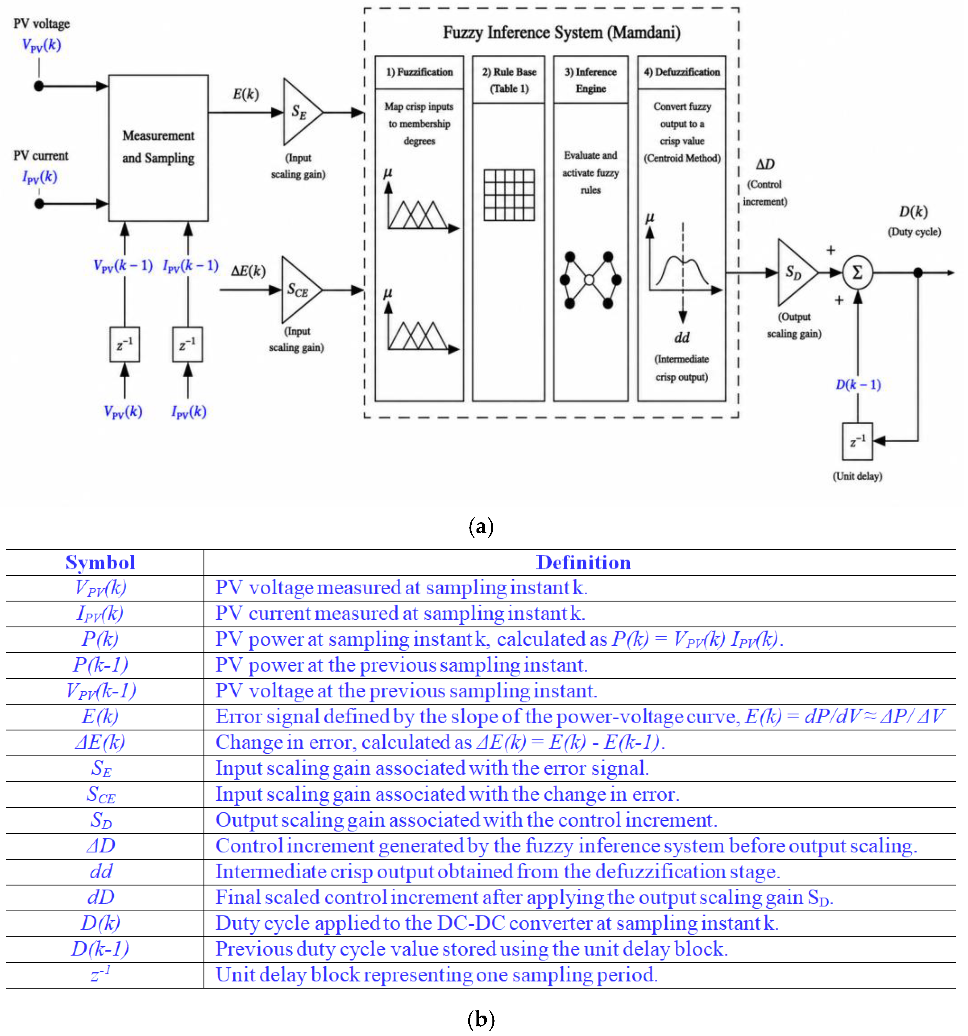
Most advanced control strategies are based on the Mamdani fuzzy inference framework originally developed for single-input/single-output systems [39]. This approach relies on a rule-based inference mechanism that emulates human reasoning through the use of linguistic variables and fuzzy sets [40]. The overall structure of the fuzzy logic controller used for MPPT implementation is illustrated in Figure 4.
In this configuration, SE and SCE denote the input scaling gains, while SD represents the output scaling gain. The fuzzy logic controller is composed of several functional stages, as follows:
  • An error computation block that evaluates both the control error (slope of the power–voltage characteristic) and its temporal variation (E(k), ΔE(k)).
  • Scaling gain factors associated with the error, the change in error, and the output variation (ΔD).
  • A fuzzification stage that maps crisp inputs into corresponding degrees of membership within predefined fuzzy sets.
  • An inference engine that evaluates and activates the fuzzy rule base according to the fuzzified inputs.
  • A defuzzification stage that converts fuzzy outputs into a single crisp control action (ΔV).
  • A summation stage that combines the control increment with its previous state to generate the final control output.
The error E(k) is defined based on the derivative of the PV power with respect to the voltage. At the MPP, the slope of the power–voltage characteristic becomes zero. Therefore, when E(k) tends to zero, the operating point approaches the MPP. The variation in the error ΔE(k) provides information regarding the convergence behavior of the controller. The output disturbance or increment corresponds to the voltage adjustment generated by the fuzzy controller at each iteration in order to update the duty cycle of the DC–DC converter. Collectively, these components enable the formulation of control decisions in linguistic form by representing error magnitudes, their rates of change, and the corresponding control actions within a fuzzy rule-based framework. The resulting rule base allows the construction of decision tables that map operating conditions to the corresponding control outputs [42,43]. Following extensive simulations and tuning under different output partitions and rule allocation strategies, the optimized fuzzy rule set is summarized in Table 3. The fuzzy rule base employs seven linguistic variables, namely NG (negative large), NM (negative medium), NP (negative small), Z (zero), PP (positive small), PM (positive medium), and PG (positive large).

2.2. Slide Mode Control (SMC)

The SMC technique is widely recognized for its robustness in nonlinear systems. The design of an SMC-based controller generally involves several key steps [20]: (i) selection of the sliding surface, (ii) verification of its attractiveness, and (iii) analysis of system stability along the sliding manifold.
The MPP condition is defined as
d P p v d V p v = 0
where Ppv denotes the PV output power, and Vpv represents the PV terminal voltage.
The corresponding switching control law is given by
u = 1         i f         S x > 0 0         i f         S x < 0
where u is the switching control signal and S(x) is the sliding surface function used to determine the operating region relative to the MPP.
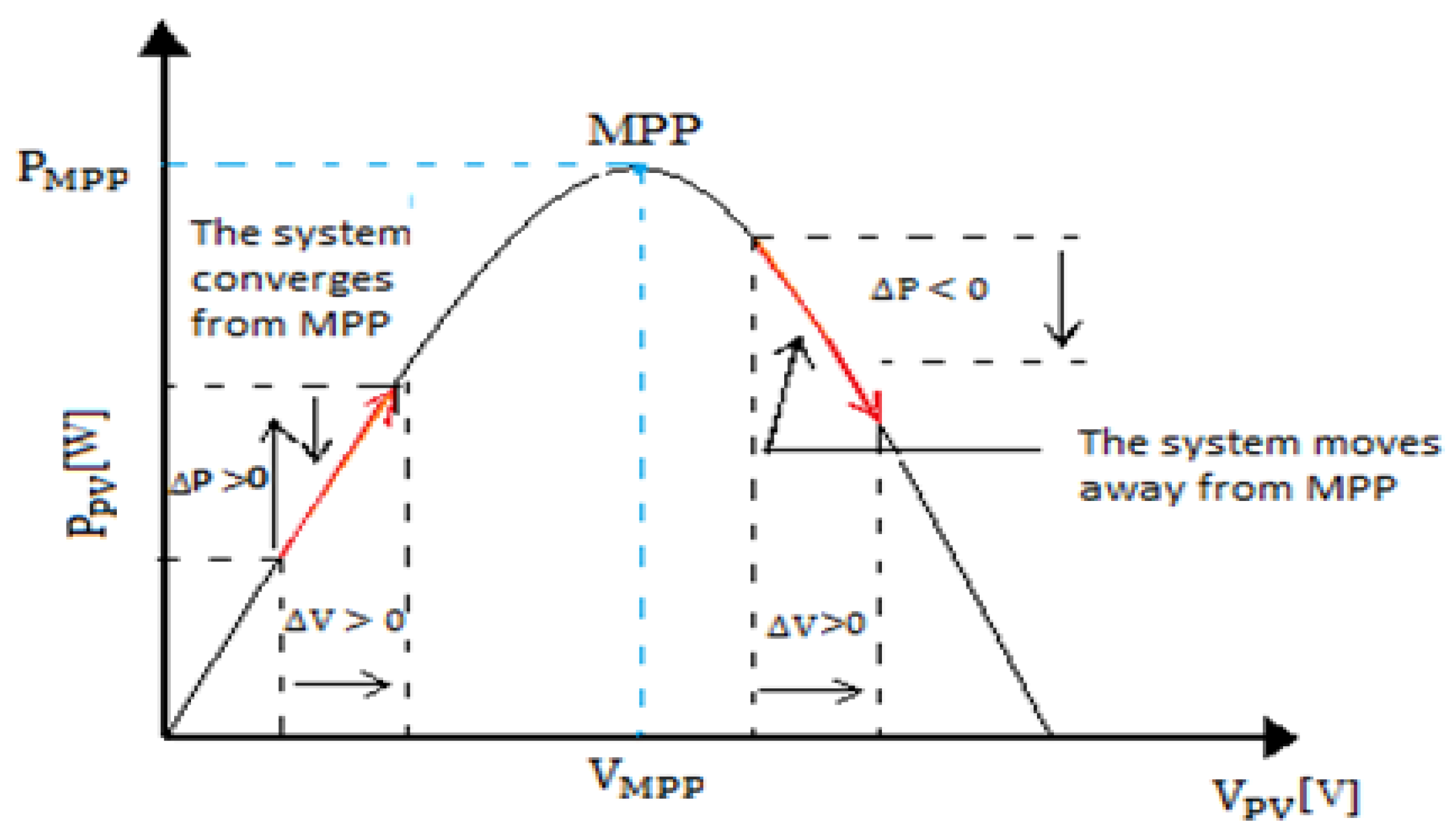
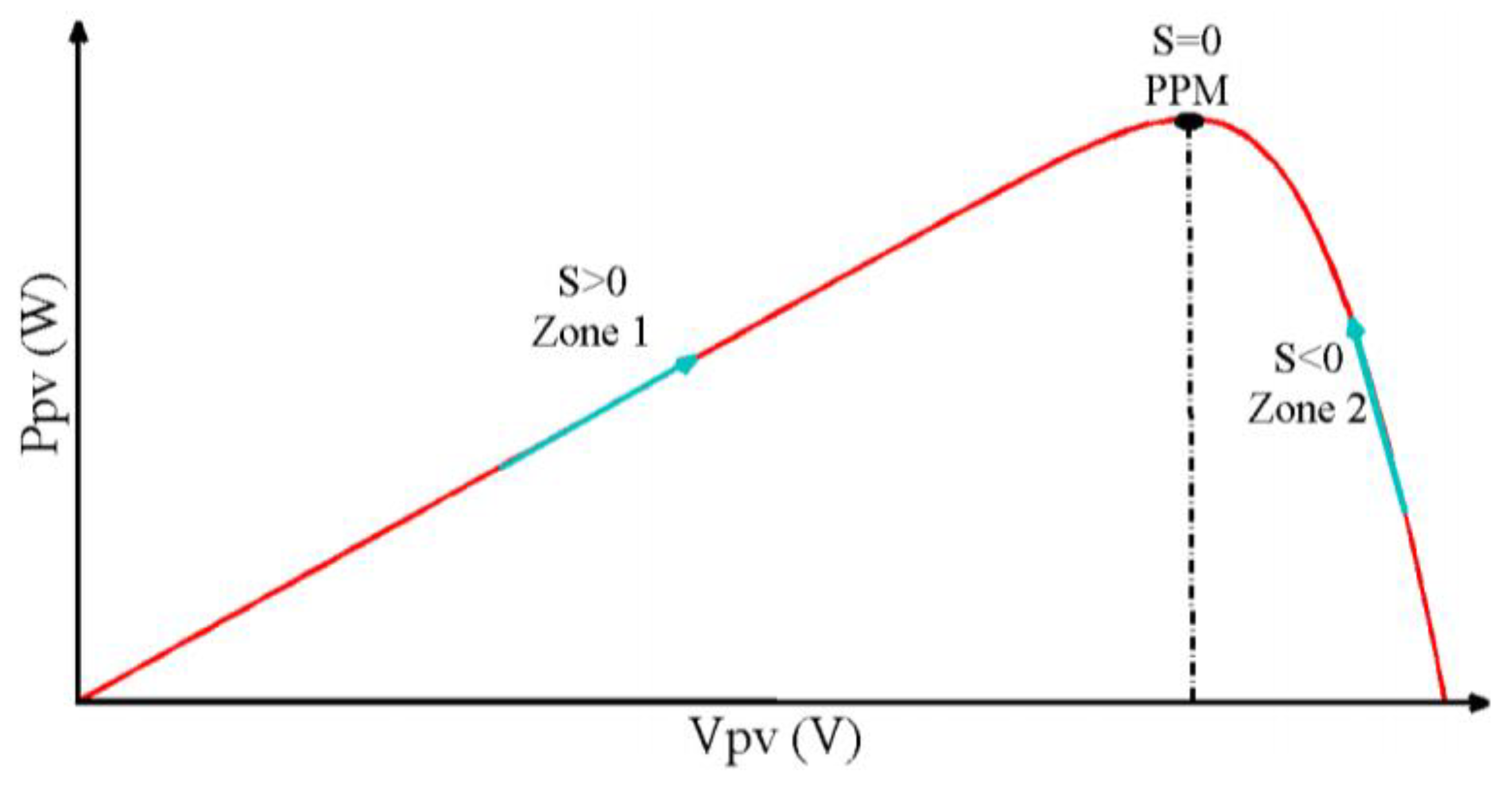
The operating regions can be interpreted using the power–voltage characteristic shown in Figure 5. In Region 1, where S(x) > 0, the operating voltage must be increased to reach the MPP. Conversely, in Region 2, where S(x) < 0, the voltage must be reduced to converge toward the MPP. Accordingly, the global SMC law [14,18] can be expressed as
u = u e q k   s i g n s = 1 V p v V 0 k   s i g n ( I p v +   d I p v d V p v   V p v )
where ueq represents the equivalent control component, k is the switching gain coefficient, V0 is the reference output voltage, Ipv is the PV output current, and dIpv/dVpv represents the incremental conductance term corresponding to the derivative of the PV current with respect to the PV voltage.

2.3. Perturb and Observe (P&O) Algorithm

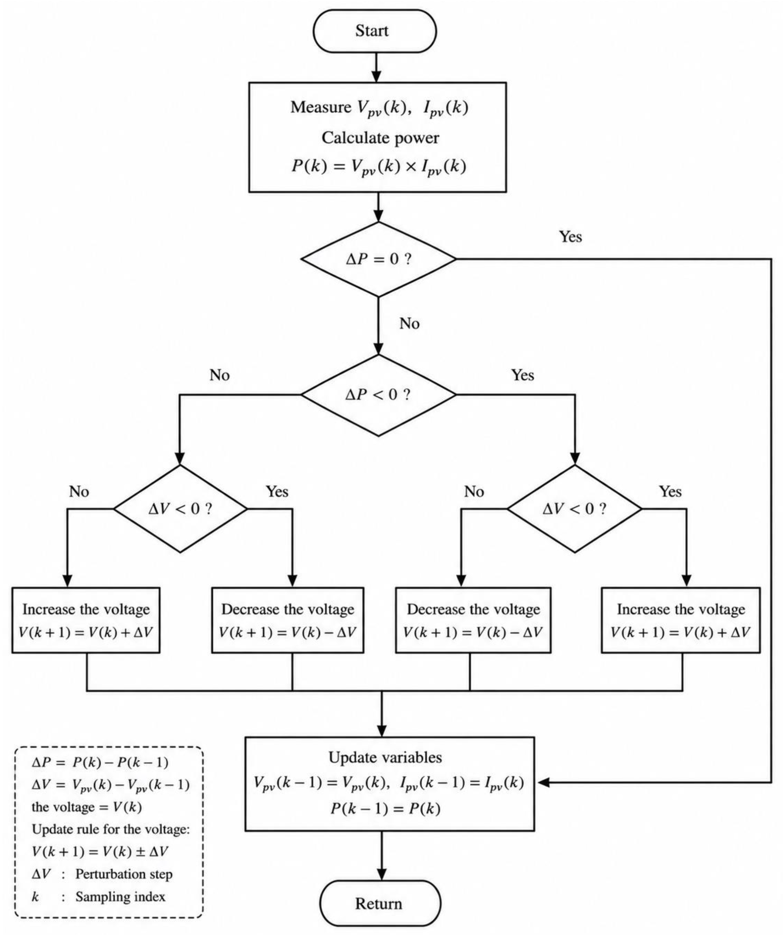
The P&O-based MPPT method operates by applying small perturbations to the PV operating voltage and observing the resulting variations in output power (PPV) [41]. As illustrated in Figure 6, an increase in PV voltage (VPV) that leads to an increase in P_PV indicates that the operating point is located on the left-hand side of the MPP. Conversely, if the output power decreases following a voltage increment, the operating point has crossed the MPP and moved toward the right-hand side of the MPP. A similar principle applies when the voltage is decreased, where the direction of the next perturbation is determined according to the observed variation in power [43]. The updated operational sequence of the P&O algorithm is illustrated in Figure 7. During each optimization cycle, the PV voltage and current are measured and used to calculate the instantaneous PV power (PPV). The algorithm then evaluates the variations in power and voltage between two successive sampling instants, represented by ΔP and ΔV, respectively. Based on the signs of these quantities, the operating voltage is perturbed in the appropriate direction to move the operating point toward the MPP. If the output power increases after perturbation, the perturbation direction is maintained; otherwise, the perturbation direction is reversed. The updated operating voltage is subsequently applied to generate the duty-cycle command of the DC–DC converter, and the process is continuously repeated at each sampling interval. In this study, the initial duty cycle was selected as 0.5 to provide a stable mid-range operating point for the converter during the initialization stage of the MPPT process. In addition, the perturbation step size (ΔD) was selected as a small positive constant to achieve a compromise between convergence speed and steady-state oscillations. These additional implementation details were incorporated into the revised manuscript to improve the clarity, reproducibility, and technical completeness of the P&O algorithm description.
Despite its simplicity and ease of implementation, the P&O-based MPPT technique exhibits several inherent limitations [43], including:
  • Oscillations around the MPP, leading to steady-state losses;
  • Degraded performance under rapidly changing irradiance conditions;
  • Relatively slow dynamic response;
  • Reduced efficiency under low irradiance levels.

2.4. Artificial Neural Network-MPPT

ANNs are computational models inspired by the structure of the human brain, consisting of interconnected processing units known as neurons. These neurons are organized in layers and operate in parallel to process input data, apply nonlinear transformations through activation functions, and propagate outputs to subsequent layers. The typical architecture includes an input layer, one or more hidden layers, and an output layer, enabling the network to learn complex nonlinear mappings between inputs and outputs. This learning capability allows ANNs to adapt to varying operating conditions and generalize effectively to unseen data, making them particularly suitable for prediction, classification, and control applications in dynamic energy systems [44]. Each neuron contributes to the overall computation by transforming input signals into a single output value, and collectively, these interconnected units form a hierarchical learning structure [45,46].
However, several limitations must be considered when applying ANN-based MPPT techniques. The performance of the model is highly dependent on the quality, diversity, and representativeness of the training dataset, which directly influences its generalization capability under varying irradiance and temperature conditions. In addition, ANN-based methods impose a higher computational burden compared to conventional MPPT algorithms, which may limit their real-time implementation on embedded platforms with constrained processing resources. Furthermore, accurate real-time tracking can be affected by sampling rate limitations, particularly under fast-changing environmental conditions, potentially introducing transient deviations from the true MPP. Following dataset construction, the neural network architecture must be defined prior to training. In this work, a two-input, single-output structure is adopted. Based on extensive simulation and experimental evaluation, a hidden layer comprising eight neurons was found to provide an optimal balance between accuracy and computational efficiency [47,48].

3. Proposed ANN-Based MPPT Approach

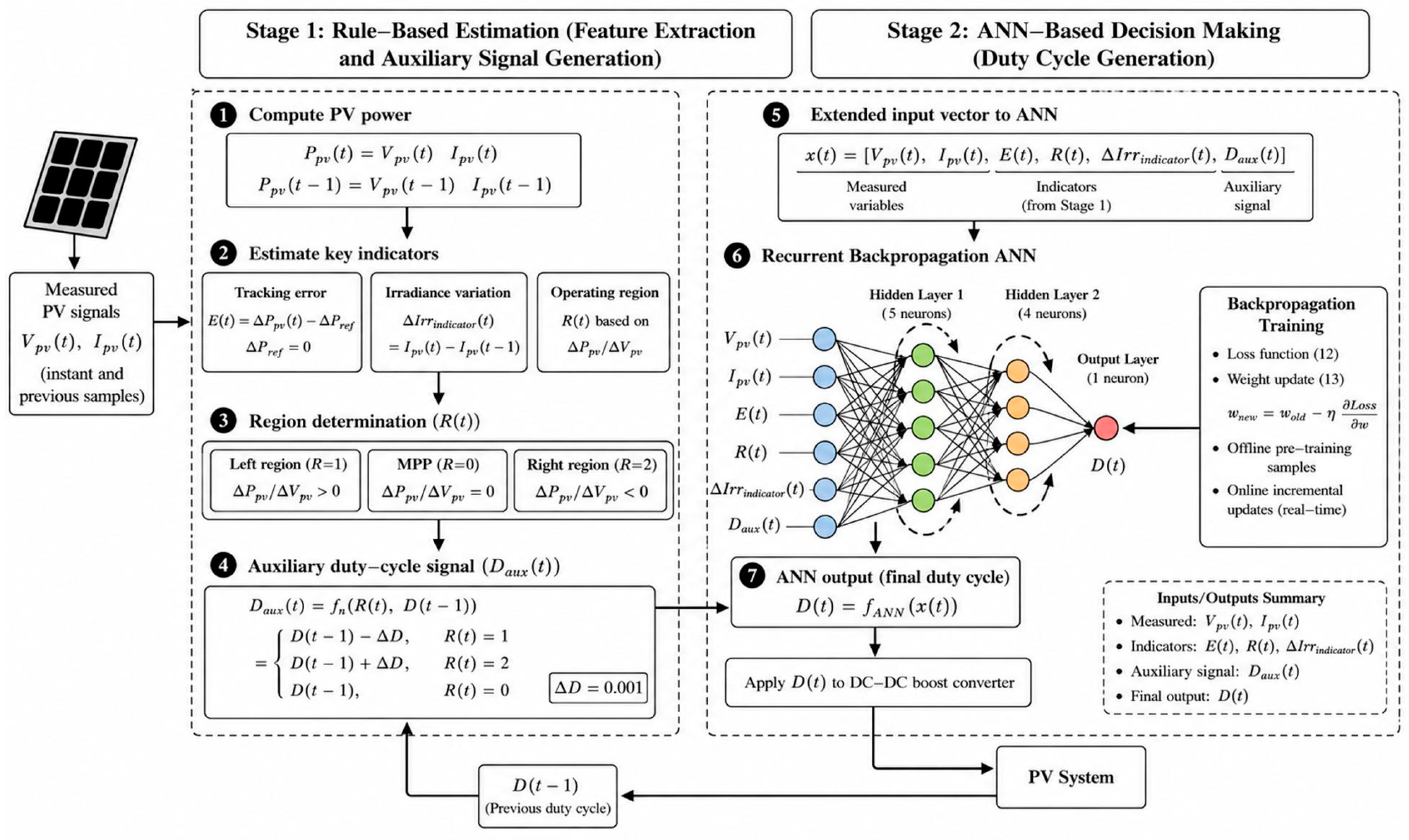
The proposed MPPT method adopts a hybrid control structure that integrates a rule-based estimation stage with an ANN-based decision-making stage. In the first stage, the operating condition is estimated using a set of deterministic heuristic equations to determine the operating region and generate auxiliary control signals. In the second stage, a backpropagation ANN refines the control action and produces the final duty cycle based on these signals. The overall system architecture is illustrated in Figure 8.
The first stage processes the measured PV voltage and current (instant and previous samples) to estimate key operating indicators, namely the tracking error E(t), the irradiance variation indicator ΔIrrindicator(t), and the operating region indicator R(t). The R(t) represents an indicator of the operating region relative to the MPP through the P-V operating characteristic. It depends on the estimated slope of power variation with respect to voltage (ΔPpvVpv). The operating region indicator R(t) takes one of three possible values: R(t) = 1 indicates operation in the left region relative to the MPP, R(t) = 2 indicates operation in the right region relative to the MPP, and R(t) = 0 corresponds to operation at the MPP. Based on the estimated operating region and the previous duty cycle D(t−1), the auxiliary duty-cycle signal Daux(t) is generated as defined in (4).
D a u x ( t ) = f n ( R t   ,     D t 1 )  
where fn(⋅) represents a lightweight mapping function that provides guidance based on the estimated operating condition. These calculations are illustrated in detail as follows:
Firstly, the power of the instant sample P p v t   and that of the previous sample P p v t 1   are calculated as
P p v t k = V p v t k · I p v t k
where k is 0 and 1.
Secondly, the tracking error E(t) is estimated as in (6).
E t = Δ P p v t Δ P r e f
where Δ P r e f = 0   to track the optimum target and Δ P p v t   is equal to P p v t P p v t 1 . Furthermore, the irradiance variation indicator ΔIrrindicator(t) is defined in (7).
I r r i n d i c t o r ( t ) = I p v t I p v t 1  
where I p v t and I p v t 1   denote the measured photovoltaic (PV) current at the present and previous sampling instants, respectively. The irradiance variation is inferred indirectly by monitoring the change in current, since variations in irradiance are physically reflected in the corresponding change in the maximum power. Although the exact MPP under the new irradiance condition is unknown, the current variation provides a reliable indicator, particularly because the voltages at the MPPs vary within a relatively narrow range under irradiance variations.
Thirdly, the region is obtained based on the sign of ΔPpvVpv as in (8). Also, if the ΔVpv is zero, the sign of ΔPpv is sufficient in the same manner. In other words, a positive value of ΔPpvVpv indicates that the operating point is located on the left-hand side of the MPP, where the PV power increases with increasing voltage. Conversely, a negative value implies operation on the right-hand side of the MPP, where the PV power decreases as the voltage increases. The variation of ΔPpvVpv characterizes the dynamic movement of the operating point during the tracking process and provides insight into the convergence behavior of the controller.
R ( t ) = 1   L e f t   r e g i o n ,           P p v V p v > 0 2   R i g h t   r e g i o n ,       P p v V p v < 0     0   M P P ,                         P p v V p v = 0
Finally, auxiliary duty-cycle signal Daux(t) is estimated as a function of the region R(t) and the previous duty cycle of the whole approach D(t−1) using (9) considering the DC–DC boost converter as follows:
D a u x ( t ) = f n ( R t   ,     D t 1 ) =   D t 1 Δ D ,               R t   = 1   D t 1 + Δ D ,               R t   = 2       D t 1 ,                               R t   = 0
where ΔD is equal to 0.001.
The final ANN-based controller in Stage 2 receives an extended input vector x as follows:
x = V p v t ,   I p v t ,   E t ,   R t ,   I r r i n d i c a t o r ,   D a u x ( t )
Although some of the inputs are derived from related computations in the first stage, they collectively provide complementary information describing the operating region, the dynamics of the tracking error, and the control guidance generated by the rule-based estimation stage. Their joint use enriches the input representation without introducing redundancy.
Additionally, the final duty cycle is produced as
D t = f A N N ( x t )  
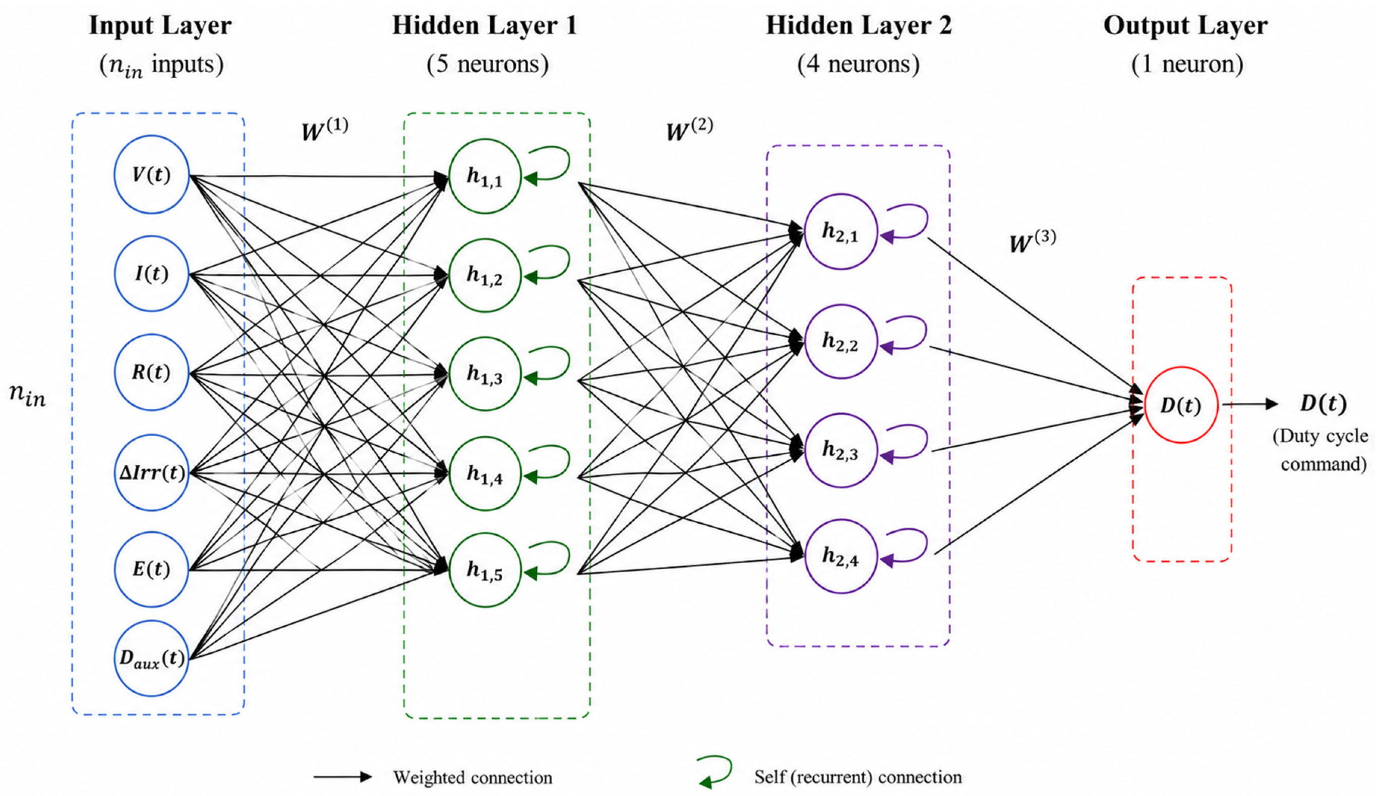
The proposed ANN-based controller is implemented as a recurrent backpropagation neural network consisting of two hidden layers with five and four neurons, respectively, and one neuron at the output layer, which generates the duty-cycle command signal, as shown in Figure 9. The recurrent architecture incorporates self-feedback connections within the hidden layers, enabling the network to retain information from the previous operating state and thereby improve the dynamic tracking capability of the controller. Also, the features of the ANN employed in this study are listed in Table 4. The hyperbolic tangent (tanh) activation function is employed in both hidden layers due to its nonlinear mapping capability and smooth convergence characteristics. As shown in (11), the input vector of the ANN is composed of the guidance signal Daux(t), the measured variables (V(t) and I(t)), and the intermediate features E(t), R(t), and ΔIrrindicator(t). The network output represents the estimated duty cycle D(t), as expressed in (11).
The ANN is trained using the backpropagation error method with a gradient descent-based optimizer. During the training process, the network learns the nonlinear relationship between the input feature vector and the optimal duty-cycle output by minimizing the loss function defined in (12). The weight adaptation process is performed iteratively as in (13). The ANN is initially trained offline using a simulated dataset and subsequently refined online using lightweight incremental updates during real-time MPPT operation.
The adopted loss function is expressed as the squared tracking error:
L o s s t = E t 2 + λ   1 ·   w t · ( D t D a u x ( t ) ) 2 + λ   2 ( D t D t 1 ) 2  
where E(t) is the tracking error, and it is defined in (6). λ1 and λ2 are positive hyperparameters used to balance the contribution of each term. The weighting factor (w(t)) is adaptively determined, and it depends on E(t). The first term, the power tracking term, focuses on the main MPPT objective to track the MPP, helping the system stay close to the optimal operating point for efficient energy harvesting under changing conditions. The second term, the guidance consistency term, encourages the controller to follow D a u x ( t ) in an adaptive manner rather than enforcing fixed rules. When the system is in a transient state or the tracking error is large, the contribution of the guidance term increases, and the variation step increases to speed up convergence. In a steady state, it decreases. The third term, the smoothness regularization term, limits rapid duty-cycle changes, leading to smoother control behavior, reduced oscillations around the MPP, and improved stability and practical implementation. The weighting factors λ1 and λ2 are selected to balance the trade-off between fast tracking response, adherence to rule-based guidance, and steady-state stability. In particular, λ1 regulates the influence of the auxiliary control signal, while λ2 controls the smoothness of the duty-cycle variation. Furthermore, adaptive weighting is performed based on the tracking error magnitude, allowing the controller to prioritize rapid convergence during transient conditions and enhanced stability under steady-state operation. In other words, larger values of λ1 increase the contribution of the auxiliary guidance term, which enhances the transient convergence speed of the controller. Conversely, increasing λ2 improves the smoothness of the duty-cycle response and helps reduce steady-state oscillations.
The weight adaptation process is performed iteratively using the gradient of the loss function with respect to the network weights. The weight update mechanism is expressed as
w n e w = w o l d η   L o s s w
where w denotes the network weights, and η represents the learning rate. The gradients are computed through the backpropagation process and propagated backward from the output layer to the hidden layers to adjust the connected weights accordingly.
A dataset containing 350 samples is generated theoretically using a MATLAB/Simulink model under different operating conditions. Various initial irradiance levels and irradiance variation patterns are randomly selected to increase the diversity of the dataset and improve the generalization capability of the network. The dataset is divided into 70% for training, 15% for validation, and 15% for testing. The training process is terminated once the loss function converges below a predefined threshold or when negligible improvement is observed between successive iterations.
The proposed control strategy is implemented and evaluated in MATLAB/Simulink 2023 using a fixed-step simulation framework. The numerical solver is configured as ode4 (Runge–Kutta) with a fixed-step size of 5 µs, corresponding to a 200 kHz sampling frequency, to ensure numerical stability and accurate representation of the system dynamics.

4. Results and Discussions

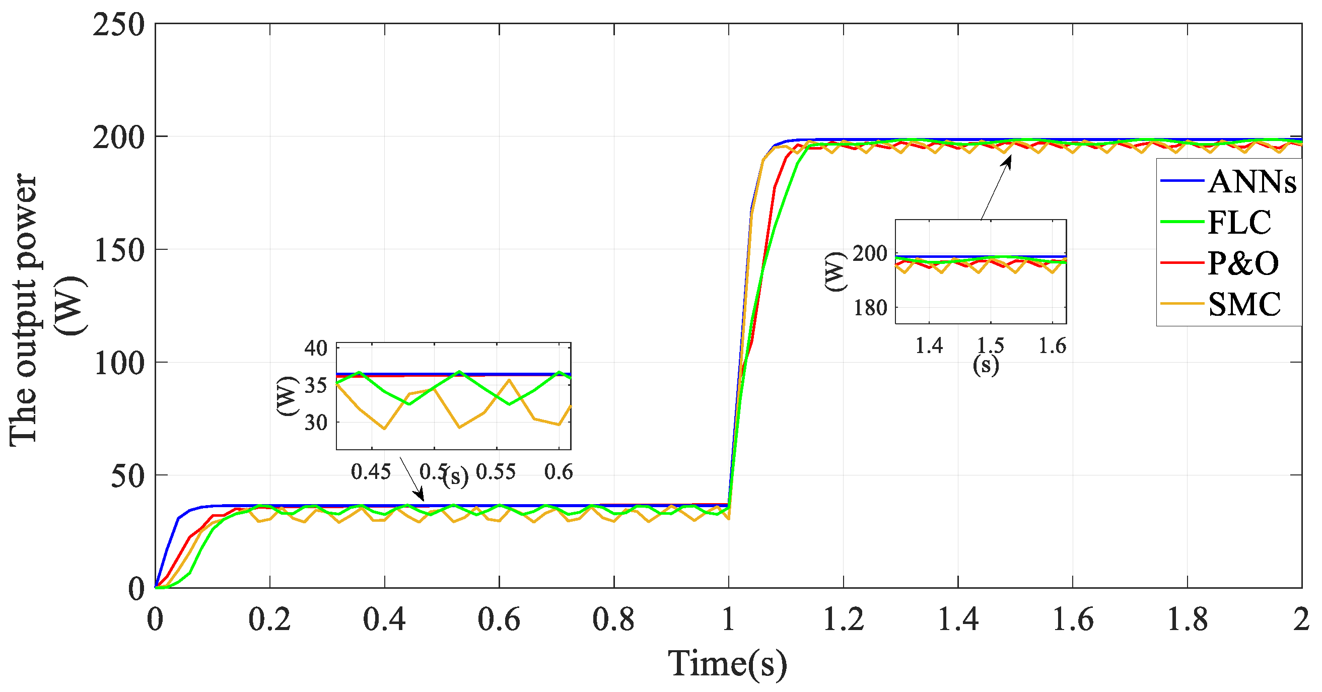
The solar system is tested under different MPPT control strategies—the proposed ANN and other existing techniques, such as FLC, SMC, and P&O—under sudden changes in irradiance conditions (from 200 W/m2 to 1000 W/m2). The value of the obtained maximum power and the required time by the proposed control are computed and compared to the considered conventional techniques.
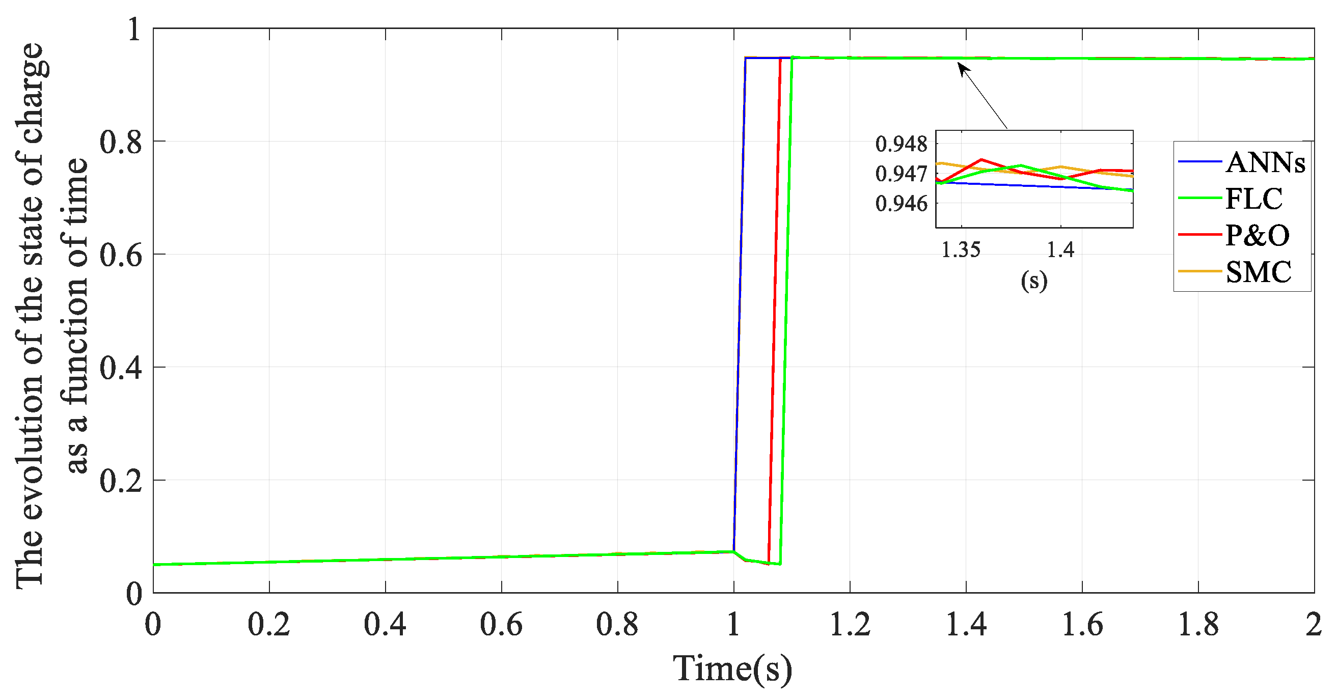
The output power response and the evolution of the state of charge of these techniques as a function of time are depicted in Figure 10 and Figure 11, respectively. The results confirm that the proposed ANN-based controller has superior performance by reaching a higher average extracted power in the lowest settling time compared to the other considered methods. On the other hand, the conventional FLC and P&O methods achieve lower average extracted power with longer settling times. Therefore, the results in Figure 10 and Figure 11 confirm that the proposed ANN-based controller demonstrates superior performance compared to both P&O and FLC during rapid irradiance increases.
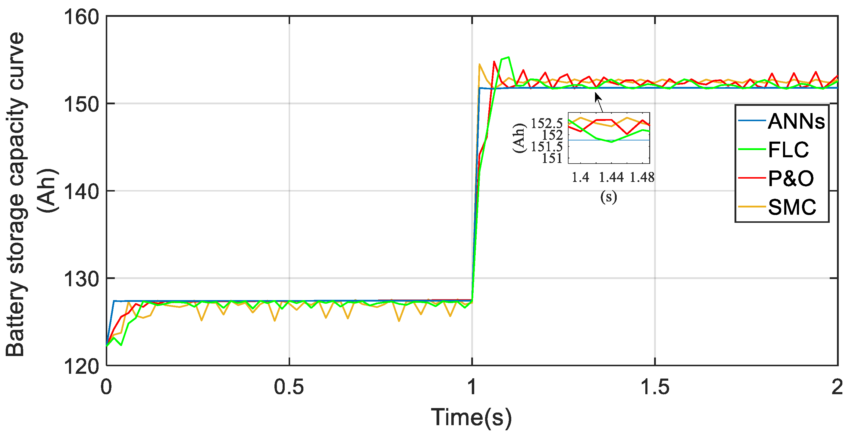
Figure 12 illustrates the battery’s storage capacity as a function of time for both the proposed control and the other considered existing methods. Under the proposed control strategy, the battery charges effectively, stabilizing at approximately 152.5 Ah in the steady state. Due to the sudden increase in the irradiance level, the ANN-based controller achieved a faster steady-state response compared with the other investigated methods, including P&O, SMC, and FLC. Furthermore, the proposed control response is characterized by lower oscillations around the MPP than the considered existing methods. Therefore, the proposed control enhances the reliability of the tracking of MPP.
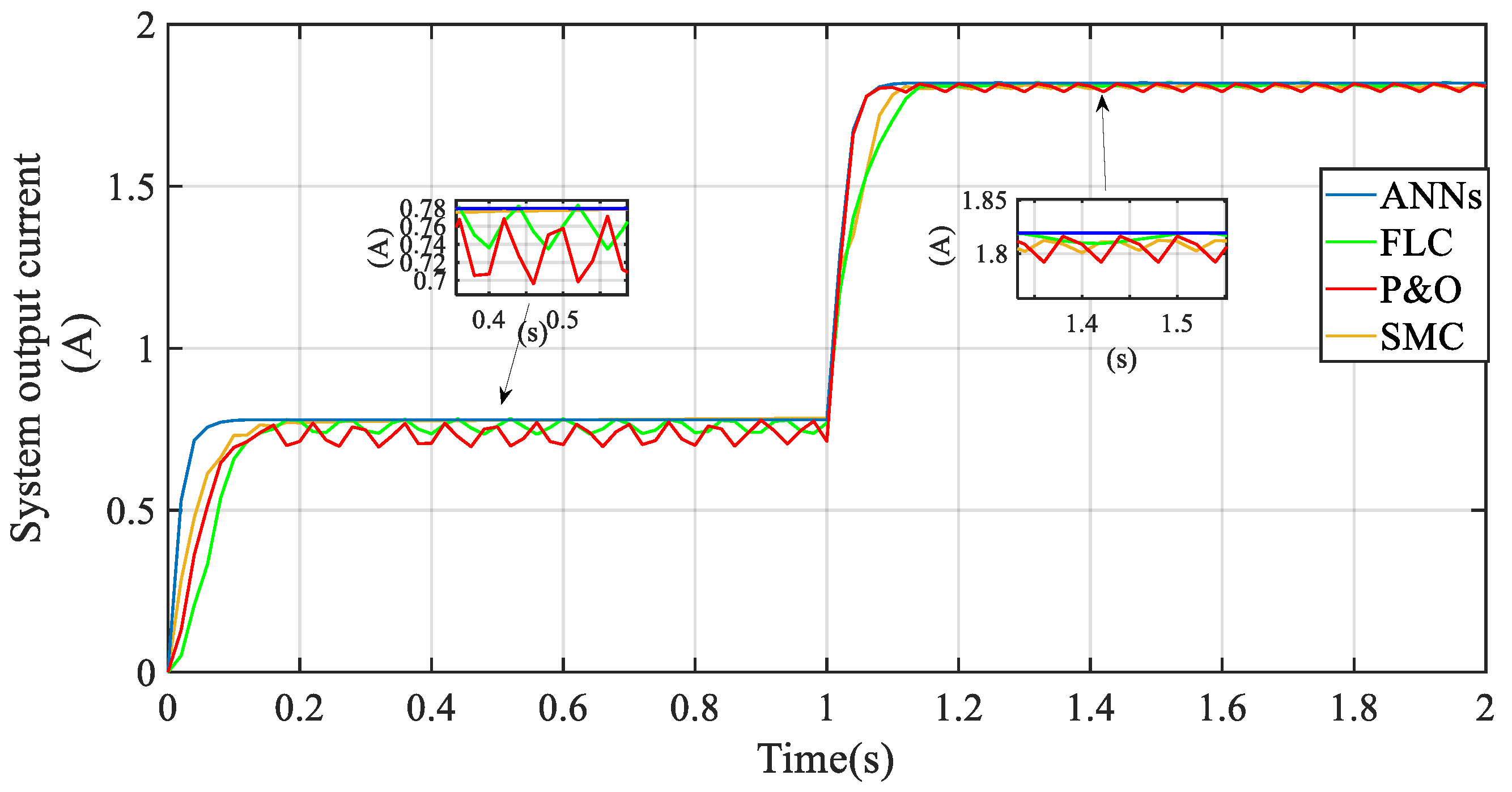
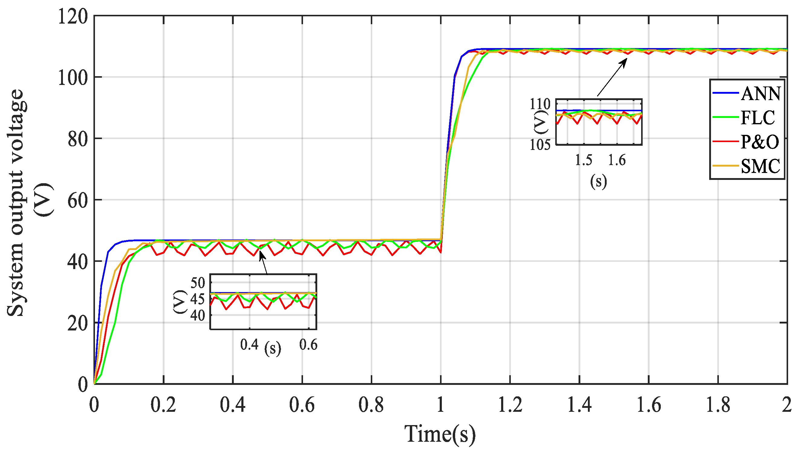
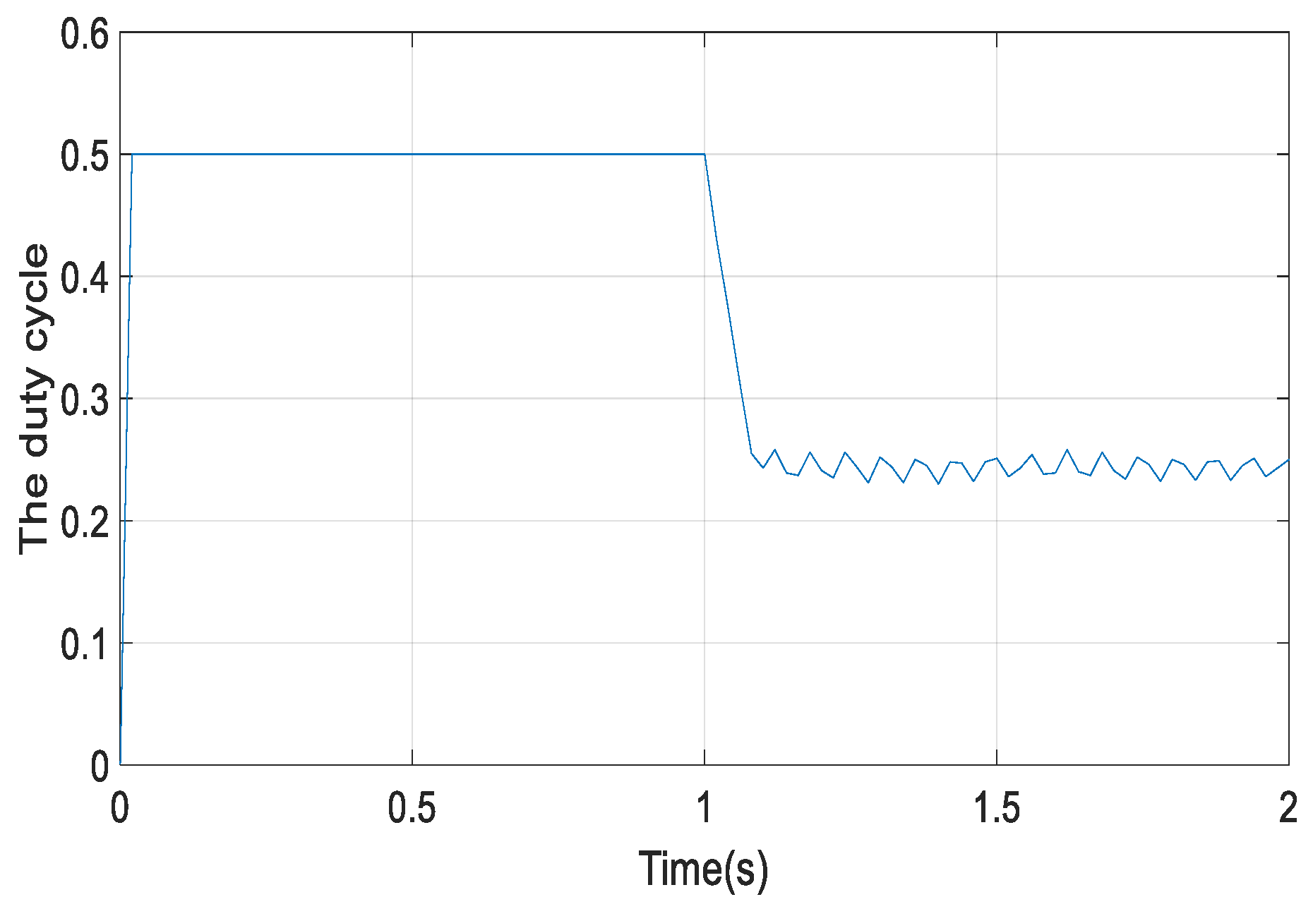
As illustrated in the previous results, the proposed control enhances the tracking trajectory of the MPP in both transient and steady-state phases, outperforming P&O, SMC, and FLC by quickly correcting deviations caused by sudden changes in environmental conditions. Figure 13 and Figure 14 further illustrate the enhanced performance of both current and voltage under varying irradiance. The profiles of voltage and current are quickly adjusted to the new optimum values corresponding to the new maximum power point in a more synchronized and stable manner than other existing methods. The proposed control reaches the new MPP faster than the other methods due to its ability to obtain the optimum duty cycle faster than these methods. Figure 15 shows that the proposed control reached the new optimum duty cycle at the lowest settling time. Accordingly, the proposed ANN-based MPPT demonstrates improved reliability due to its reduced settling time, higher efficiency, and lower oscillatory behavior compared with the investigated conventional methods. Overall, the ANN-based MPPT exhibits a fast dynamic response and a stable steady-state power output, even under rapidly changing irradiance. In contrast, the P&O, SMC, and FLC methods require longer settling times and show greater oscillatory behavior around the MPP.
The comparative performance metrics presented in Table 5 were evaluated using the output power responses obtained under identical irradiance variation conditions for all investigated MPPT approaches. The MPPT efficiency was determined as the ratio between the average extracted PV power and the theoretical maximum available power under the corresponding operating conditions. The ripple magnitude was evaluated from the difference between the maximum and minimum power values during steady-state operation, while the oscillation amplitude was estimated as half of the steady-state ripple range [49]. The overshoot percentage was calculated based on the maximum transient power deviation relative to the reference steady-state value. In addition, the settling time was defined as the time required for the output power response to enter and remain within a predefined tolerance band around the final operating point. The tracking error was evaluated from the deviation between the extracted PV power and the corresponding maximum power point reference. Furthermore, the harvested energy was estimated from the integral of the output power over the simulation interval.
Based on the obtained results, the proposed ANN-based MPPT approach achieved the highest tracking efficiency of 99.6%, together with the lowest ripple magnitude (2.4 W), minimum oscillation amplitude (1.2 W), and lowest tracking error among the investigated techniques. The FLC-based controller also demonstrated favorable dynamic behavior with relatively low oscillations and acceptable convergence characteristics, achieving an efficiency of 98.74%. In contrast, the conventional P&O algorithm exhibited larger oscillations, higher ripple magnitude, and slower convergence characteristics due to its perturbation-based operating principle. Although the SMC-based approach maintained acceptable robustness and dynamic response, relatively larger oscillations and ripple levels were still observed compared with the proposed ANN-based approach. Overall, the improved convergence characteristics and reduced oscillatory behavior achieved by the proposed ANN-based strategy contributed to enhanced energy harvesting capability under abrupt irradiance variations.

5. Conclusions

This study presents a hybrid ANN-based MPPT strategy for photovoltaic systems operating under dynamic irradiance conditions. The proposed framework integrates a rule-based estimation stage with a neural network-based control stage to enhance the overall tracking performance and dynamic response. In the first stage, key operating indicators, including the tracking error, irradiance variation, and operating region, are extracted from the measured PV voltage and current signals. These indicators are then utilized to construct an auxiliary duty-cycle signal that provides guidance for the subsequent control action. In the second stage, a backpropagation neural network is employed to generate the final duty-cycle command using both the extracted indicators and the measured electrical variables as inputs. The network is initially trained offline using a simulated dataset and is subsequently updated online through a lightweight incremental learning scheme, ensuring adaptation capability without imposing a significant computational burden.
Simulation results in MATLAB/Simulink under abrupt irradiance variations demonstrate improved tracking performance and reduced steady-state oscillations when compared with conventional MPPT techniques such as P&O, FLC, and SMC. Future work will focus on experimental validation and further extension of the proposed framework toward fault-tolerant photovoltaic control applications. Furthermore, future work will focus on enhancing the neural network’s ability to handle gradual irradiance variations.

Author Contributions

Conceptualization, M.E., R.L. and M.A.E.; Methodology, M.E. and M.A.E.; Software, R.L.; Formal analysis, M.E. and M.A.E.; Investigation, M.E.; Data curation, R.L.; Writing—original draft, R.L.; Writing—review & editing, M.E. and M.A.E.; Visualization, R.L. and M.A.E. All authors have read and agreed to the published version of the manuscript.

Funding

This research was supported by the College of Engineering, Department of Electrical and Computer Engineering, Sultan Qaboos University, through Internal Grant IG/ENG/ECED/25/04.

Data Availability Statement

The original contributions presented in this study are included in the article. Further inquiries can be directed to the corresponding author.

Conflicts of Interest

The authors declare no conflict of interest.

Abbreviations

The following abbreviations are used in this manuscript:
ANNsNeural networks
FLCFuzzy logic control
FNTSMFast non-singular terminal sliding mode
MPPMaximum power point
MPPTMaximum power point tracking
NTSMNon-singular terminal sliding mode
PVPhotovoltaic system
SMCSliding mode control
TSMTerminal sliding mode

References

  1. Oman Vision 2040 Implementation Follow-Up Unit. Oman Vision 2040. Government of Oman. 2024. Available online: https://www.oman2040.om (accessed on 11 April 2026).
  2. Ministry of Transport, Communications and Information Technology (MTCIT). Digital Transformation Program (Tahawul), Sultanate of Oman. Available online: https://tahawul.mtcit.gov.om (accessed on 11 April 2026).
  3. Shubham. Oman Self-Healing Networks Market Report: Size, Share, Growth Drivers, Trends, Opportunities & Forecast 2025–2030. Ken Research. 2025. Available online: https://www.kenresearch.com/oman-self-healing-networks-market (accessed on 11 April 2026).
  4. Times News Service. Oman to Generate 30% of Power from Renewables by 2030. Times of Oman. 31 May 2025. Available online: https://timesofoman.com/article/158753-oman-to-generate-30-of-power-from-renewables-by-2030 (accessed on 11 April 2026).
  5. Alhinai, H.A.; Ariffin, A.M.; Osman, M. Revolutionizing Oman’s energy network with an optimal mixture renewable energy source. AIMS Energy 2023, 11, 628–662. [Google Scholar] [CrossRef]
  6. Ministry of Energy and Minerals (MEM). Renewable Energy. Available online: https://mem.gov.om/public/renewable-energy (accessed on 11 April 2026).
  7. Watts, N. Oman Targets Renewable Growth and Grid Modernization to Meet Vision 2040. Utilities Middle East. 12 September 2025. Available online: https://www.utilities-me.com/news/oman-renewable-grid (accessed on 11 April 2026).
  8. Ministry of Energy and Minerals (MEM). Oman Net Zero. Available online: https://mem.gov.om/public/oman-net-zero (accessed on 6 April 2026).
  9. Al-Shidhani, M.A.; Hayyan, M. Oman’s energy transition roadmap to net zero 2050. Energy Nexus 2025, 19, 100493. [Google Scholar] [CrossRef]
  10. Markvart, T.; Castañer, L. Practical Handbook of Photovoltaics: Fundamentals and Applications, 2nd ed.; Elsevier: Oxford, UK, 2012. [Google Scholar]
  11. Bouhafs, A.; Kafi, M.R.; Louazene, L.; Rouabah, B.; Toubakh, H. Fault-Detection-Based Machine Learning Approach to Multicellular Converters Used in Photovoltaic Systems. Machines 2022, 10, 992. [Google Scholar] [CrossRef]
  12. Alkuhayli, A.; Noman, A.M.; Al-Shamma’a, A.A.; Abdurraqeeb, A.M.; Alharbi, M.; Hussein Farh, H.M.; Qamar, A. Enhancing Photovoltaic-Powered DC Shunt Motor Performance for Water Pumping through Fuzzy Logic Optimization. Machines 2024, 12, 442. [Google Scholar] [CrossRef]
  13. Ibrahim, T.; Abou Akrouch, M.; Hachem, F.; Ramadan, M.; Ramadan, H.S.; Khaled, M. Cooling Techniques for Enhanced Efficiency of Photovoltaic Panels—Comparative Analysis with Environmental and Economic Insights. Energies 2024, 17, 713. [Google Scholar] [CrossRef]
  14. Sun, B.; Lu, L.; Chen, J.; Ma, T.; Yuan, Y. Full-spectrum radiative cooling for enhanced thermal and electrical performance of bifacial solar photovoltaic modules: A nationwide quantitative analysis. Appl. Energy 2024, 362, 123037. [Google Scholar] [CrossRef]
  15. Talebi, H.; Nikoukar, J.; Gandomkar, M. Optimal sizing and techno-economic analysis of combined solar wind power system, fuel cell and tidal turbines using meta-heuristic algorithms: A case study of Lavan Island. Int. J. Comput. Intell. Syst. 2025, 18, 15. [Google Scholar] [CrossRef]
  16. Nebti, K.; Debbabi, F. Amelioration of MPPT P&O using fuzzy-logic technique for PV pumping. In Renewable Energy for Smart and Sustainable Cities; Springer: Cham, Switzerland, 2019; pp. 367–374. [Google Scholar]
  17. Belkaid, A.; Gaubert, J.-P.; Gherbi, A.; Rahmani, L. Maximum power point tracking for photovoltaic systems with boost converter sliding mode control. In Proceedings of the 2014 IEEE 23rd International Symposium on Industrial Electronics (ISIE), Istanbul, Turkey, 1–4 June 2014; pp. 556–561. [Google Scholar]
  18. Bouafia, A.; Krim, F.; Gaubert, J.-P. Design and implementation of high performance direct power control of three-phase PWM rectifier via fuzzy and PI controller for output voltage regulation. Energy Convers. Manag. 2009, 50, 6–13. [Google Scholar] [CrossRef]
  19. Vázquez, N.; Azaf, Y.; Cervantes, I.; Vázquez, E.; Hernández, C. Maximum power point tracking based on sliding mode control. Int. J. Photoenergy 2015, 2015, 380684. [Google Scholar] [CrossRef]
  20. Chatrenour, N.; Razmi, H.; Doagou-Mojarrad, H. Improved double integral sliding mode MPPT controller based parameter estimation for a stand-alone photovoltaic system. Energy Convers. Manag. 2017, 139, 97–109. [Google Scholar] [CrossRef]
  21. Zhang, W.; Sun, C.; Wang, Y.; Song, K. A Novel Voltage-Power Coordinated Control Strategy for Grid-Connected Inverters in Low-Voltage Microgrids Based on Fast Non-Singular Terminal Sliding Mode. Electr. Power Syst. Res. 2026, 251, 112183. [Google Scholar] [CrossRef]
  22. Zhang, W.; Sun, C.; Alharbi, M.; Hasanien, H.M.; Song, K. A Voltage-Power Self-Coordinated Control System on the Load-Side of Storage and Distributed Generation Inverters in Distribution Grid. Ain Shams Eng. J. 2025, 16, 103480. [Google Scholar] [CrossRef]
  23. Zhang, W.; Sun, C.; Zeng, Y.; Hasanien, H.M.; Wang, Y. Design and Dynamic Characteristic Analysis of NTSM with Variable Gains for Full-Parameter Perturbation Systems: A Case of DC-DC Converters. ISA Trans. 2026, 172, 364–384. [Google Scholar] [CrossRef] [PubMed]
  24. Xiao, W.; Dunford, W.G. A modified adaptive hill climbing MPPT method for photovoltaic power systems. In Proceedings of the 2004 IEEE 35th Annual Power Electronics Specialists Conference (IEEE Cat. No.04CH37551), Aachen, Germany, 20–25 June 2004; IEEE: Piscataway, NJ, USA, 2004; Volume 3, pp. 1957–1963. [Google Scholar]
  25. Ali, A.I.M.; Mohamed, H.R.A. Improved P&O MPPT algorithm with efficient open-circuit voltage estimation for two-stage grid-integrated PV system under realistic solar radiation. Int. J. Electr. Power Energy Syst. 2022, 137, 107805. [Google Scholar]
  26. Pires, V.F.; Cordeiro, A.; Foito, D.; Silva, J.F.A. Dual output and high voltage gain DC-DC converter for PV and fuel cell generators connected to DC bipolar microgrids. IEEE Access 2021, 9, 15723–15735. [Google Scholar] [CrossRef]
  27. Villegas-Mier, C.G.; Rodriguez-Resendiz, J.; Álvarez-Alvarado, J.M.; Rodriguez-Resendiz, H.; Herrera-Navarro, A.M.; Rodríguez-Abreo, O. Artificial neural networks in MPPT algorithms for optimization of photovoltaic power systems. Micromachines 2021, 12, 1260. [Google Scholar] [CrossRef]
  28. Abidi, H.; Sidhom, L.; Chihi, I. Systematic Literature Review and Benchmarking for Photovoltaic MPPT Techniques. Energies 2023, 16, 3509. [Google Scholar] [CrossRef]
  29. Roy, R.B.; Rokonuzzaman, M.; Amin, N.; Mishu, M.K.; Alahakoon, S.; Rahman, S. A comparative performance analysis of ANN algorithms for MPPT energy harvesting in solar PV systems. IEEE Access 2021, 9, 103456–103470. [Google Scholar] [CrossRef]
  30. Khosrojerdi, F.; Taheri, S.; Cretu, A.-M. An Adaptive Neuro-Fuzzy Inference System-Based MPPT Controller for Photovoltaic Arrays. In Proceedings of the 2016 IEEE Electrical Power and Energy Conference (EPEC), Ottawa, ON, Canada, 12–14 October 2016; pp. 1–6. [Google Scholar]
  31. Rahman, M.M.; Islam, M.S. PSO and ANN Based Hybrid MPPT Algorithm for Photovoltaic Array Under Partial Shading Condition. Eng. Int. 2020, 8, 9–24. [Google Scholar] [CrossRef]
  32. Allahyari, S.A.; Taheri, N.; Zadehbagheri, M.; Rahimkhani, Z. A Novel Adaptive Neural MPPT Algorithm for Photovoltaic System. Int. J. Automot. Mech. Eng. 2018, 15, 5421–5434. [Google Scholar] [CrossRef]
  33. Demirci, A.; Dagal, I.; Tercan, S.M.; Gundogdu, H.; Terkes, M.; Cali, U. Enhanced ANN-Based MPPT for Photovoltaic Systems. IEEE Access 2025, 13, 92783–92799. [Google Scholar] [CrossRef]
  34. Dawahdeh, A.; Sharadga, H.; Kumar, S. Novel MPPT Controller Augmented with Neural Network. Sustainability 2024, 16, 1021. [Google Scholar] [CrossRef]
  35. Issaadi, S.; Issaadi, W.; Khireddine, A. New Intelligent Control Strategy by Robust Neural Network Algorithm for Real-Time Detection of an Optimized Maximum Power Tracking Control in Photovoltaic Systems. Energy 2019, 187, 115881. [Google Scholar] [CrossRef]
  36. Dounis, A.I.; Kofinas, P.; Papadakis, G.; Alafodimos, C. A Direct Adaptive Neural Control for Maximum Power Point Tracking of Photovoltaic System. Sol. Energy 2015, 115, 145–165. [Google Scholar] [CrossRef]
  37. Ali, M.N.; Mahmoud, K.; Lehtonen, M.; Darwish, M.M.F. Promising MPPT Methods Combining Metaheuristic, Fuzzy-Logic and ANN Techniques for Grid-Connected Photovoltaic. Sensors 2021, 21, 1244. [Google Scholar] [CrossRef]
  38. Kyocera Corporation. KC200GT High Efficiency Multicrystalline Photovoltaic Module Datasheet; Kyocera Corporation: Kyoto, Japan, 2006. [Google Scholar]
  39. Mohan, B.G.; Suresh Babu, G.; Vidya Sagar, E. An artificial intelligent hybrid controller for solar and battery fed five-level UPQC for power quality improvement. Int. J. Renew. Energy Res. 2024, 14, 1–13. [Google Scholar] [CrossRef]
  40. Belkaid, A.; Gaubert, J.P.; Gherbi, A. An Improved Sliding Mode Control for Maximum Power Point Tracking in Photovoltaic Systems. J. Control Eng. Appl. Inform. 2016, 18, 86–94. [Google Scholar]
  41. Ahmed, J.; Salam, Z. A Modified P&O Maximum Power Point Tracking Method with Reduced Steady-State Oscillation and Improved Tracking Efficiency. IEEE Trans. Sustain. Energy 2016, 7, 1506–1515. [Google Scholar]
  42. Arsad, A.Z.; Azhar, A.D.; Arsad, S.R.; Zuhdi, A.W.M.; Chau, C.F.; Ghazali, A. Towards artificial intelligence for solar charge controller: An analytical study of recent status, optimization and module development. Energy Syst. 2025, 1–54. [Google Scholar] [CrossRef]
  43. Nebti, K.; Lebied, R. Fuzzy Maximum Power Point Tracking Compared to Sliding Mode Technique for Photovoltaic Systems Based on DC-DC Boost Converter. Electr. Eng. Electromech. 2021, 1, 67–73. [Google Scholar] [CrossRef]
  44. Zhang, C.; Li, W.; Zhang, H.; Zhan, T. Recent Advances in Intelligent Data Analysis and Its Applications. Electronics 2024, 13, 226. [Google Scholar] [CrossRef]
  45. Benbouhenni, H.; Boudjema, Z. Comparative Study Between Neural Hysteresis, Fuzzy PI, and Neural Switching Table for an IM DTC Control. Int. J. Fuzzy Syst. Adv. Appl. 2018, 5, 23–34. [Google Scholar]
  46. Micu, D.D.; Czumbil, L.; Christoforidis, G.; Simion, E. Neural Networks Applied in Electromagnetic Interference Problems. Rev. Roum. Sci. Tech. Ser. Electrotech. Energ. 2012, 57, 162–171. [Google Scholar]
  47. Akkouchi, K.; Rahmani, L.; Lebied, R. New Application of Artificial Neural Network-Based Direct Power Control for Permanent Magnet Synchronous Generator. Electr. Eng. Electromech. 2021, 6, 18–24. [Google Scholar] [CrossRef]
  48. Karabacak, K.; Cetin, N. Artificial Neural Networks for the Control of Wind and Photovoltaic Energy Systems. Renew. Sustain. Energy Rev. 2014, 29, 804–827. [Google Scholar] [CrossRef]
  49. Varshney, T.; Patnana, N.; Singh, V.P. Enhanced Frequency Regulation of Islanded Airport Microgrid Using IAE-Assisted Control with Reaction Curve-Based FOPDT Modeling. Inventions 2025, 10, 88. [Google Scholar] [CrossRef]
Figure 1. Evolution of renewable energy in Oman.
Machines 14 00659 g001
Figure 2. Oman greenhouse gas (GHG) emissions by sector.
Machines 14 00659 g002
Figure 3. Block diagram of the system.
Machines 14 00659 g003
Figure 4. General structure of the fuzzy logic controller used for MPPT implementation [41]: (a) sequence of operation and (b) symbol definition of signals and variables.
Machines 14 00659 g004
Figure 5. Power–voltage characteristic.
Machines 14 00659 g005
Figure 6. P&O principle [29].
Machines 14 00659 g006
Figure 7. Flowchart of the P&O algorithm.
Machines 14 00659 g007
Figure 8. System architecture of the proposed ANN.
Machines 14 00659 g008
Figure 9. Schematic representation of the recurrent neural network architecture.
Machines 14 00659 g009
Figure 10. The output power of the proposed ANN, along with SMC, FLC, and P&O.
Machines 14 00659 g010
Figure 11. The evolution of the state of charge as a function of time of the proposed ANN, along with SMC, FLC, and P&O.
Machines 14 00659 g011
Figure 12. Battery storage capacity curve of the proposed ANN, along with SMC, FLC, and P&O.
Machines 14 00659 g012
Figure 13. System output current of the proposed ANN, along with SMC, FLC, and P&O.
Machines 14 00659 g013
Figure 14. System output voltage of the proposed ANN, along with SMC, FLC, and P&O.
Machines 14 00659 g014
Figure 15. The duty cycle of the proposed ANN-MPPT.
Machines 14 00659 g015
Table 1. Summary of ANN-based techniques based on training inputs/outputs, operating principles, advantages, and limitations.
Ref.Working PrincipleInputsOutputsAdvantagesLimitations
[29]Compares three ANN training algorithms for predicting MPPIrradiance, temperatureGenerated voltageLevenberg–Marquardt achieved the best correlation and lowest MSEOffline training only and depends on ideal datasets
[32]Uses a neural identifier and a neural controller with online weight adaptationIrradiance, temperature, voltage, and current of sample k (V(k), I(k))Duty cycle d(k)Adaptive real-time control and fast convergenceVery high computational complexity
[33]ANN trained using metaheuristic and analytical optimization methods under PSCIrradiance, temperature, PV characteristicsOptimal voltageExtremely high efficiency and fast convergenceRequires extensive datasets and high training complexity
[34]Uses feedforward NN with conventional P&O under rapid irradiance variationsIm, ΔIm, irradiance variation
(m refers to maximum power point)
Duty cycle change ΔDmImproved dynamic tracking performanceStill dependent on P&O refinement
[35]Introduces a robust neural network-based MPPT controller designed for real-time prediction of optimal converter command under varying environmental conditionsPV voltage, PV current, irradiance, temperatureOptimal control command/duty cycleVery high tracking speed and precision, smooth control signal without oscillation, robust against measurement noiseHigh computational and implementation complexity with extensive training requirements
[36]Uses a single-neuron direct adaptive neural controller with online rule learning to directly regulate the buck converter duty cycle for MPPT without requiring irradiance or temperature measurementsPV voltage, PV current, dP/dV error, error changeDuty cycle/reference voltageOnline learning capability, fast convergence, simple single-neuron structure, no irradiance or temperature sensors required, straightforward digital implementationRequires online weight adaptation tuning
[37]Combines GA/PSO-optimized fuzzy logic MPPT with GA-optimized ANN architecture and introduces a hybrid AI-based MPPT strategy for grid-connected PV systemsPV voltage, PV current, error (E), change in error (ΔE), irradiance, temperatureDuty cycle change (ΔD)/MPPT control signalHigh tracking efficiency, improved tracking speed, optimized ANN architecture, enhanced performance under varying irradiance and temperature conditionsHigh computational complexity; requires optimization procedures and extensive ANN training datasets
Table 2. Parameters of both the KYOCERA KC200GT PV Module, chopper, battery, and load.
Parameters of the KYOCERA KC200GT PV Module
ParameterValue
PV moduleKYOCERA KC200GT
Module typePolycrystalline silicon
Maximum power200 W
Voltage at maximum power26.3 V
Current at maximum power7.61 A
Open-circuit voltage32.9 V
Short-circuit current8.21 A
Number of cells per module54
Number of strings1
Temperature coefficient of Voc−0.123 V/°C
Temperature coefficient of Isc0.0032 A/°C
Module efficiencyApproximately 16%
Maximum system voltage600 V
Boost Converter Parameters
ComponentValue
C56 µF
L350 µH
PWM10 kHz
Controller sampling time1 ms
Solver settingsFixed-step configuration, using the ode4 (Runge–Kutta) with a fixed-step size of 5 µs (200 kHz).
Load and Battery Parameters
ParameterValue
Battery typeLead–acid
Number of cells (NB)24
Nominal voltage48 V
Rated capacity82 Ah
Initial SOC95%
Minimum SOC5%
Battery terminal voltage49.55 V
Load resistance60 Ω
Table 3. Rule base of the fuzzy controller.
ΔE/ENGNMNPZPPPMPG
NGNGNGNGNGNMNPZ
NMNGNGNGNMNPZPP
NPNGNGNMNPZPPPM
ZNGNMNPZPPPMPG
PPNMNPZPPPMPGPG
PMNPZPPPMPGPGPG
PGZPPPMPGPGPGPG
Table 4. Features of the ANN employed in this study.
FeatureDescription
Neural network typeRecurrent backpropagation neural networks
Hidden layers2
Neurons of first layer5
Neurons of second layer4
Input variables V p v t ,   I p v t ,   E t ,   R t ,   I r r i n d i c a t o r ,   D a u x ( t )
Output variable D t
Table 5. Comparative performance analysis of the proposed ANN-based MPPT and conventional techniques.
MethodEfficiency (%)Ripple (W)Overshoot (%)Settling Time (s)Tracking ErrorSteady-State Oscillation (W)Relative Energy Harvested
Proposed ANNs99.62.40.50.06Very Low1.2Highest
FLC [43]98.743.61.00.14Low1.8Very High
P&O [16]97.55.22.00.125Moderate2.6Moderate
SMC [40]97.26.731.50.14Moderate3.365Moderate–High
Disclaimer/Publisher’s Note: The statements, opinions and data contained in all publications are solely those of the individual author(s) and contributor(s) and not of MDPI and/or the editor(s). MDPI and/or the editor(s) disclaim responsibility for any injury to people or property resulting from any ideas, methods, instructions or products referred to in the content.