Article

Dynamic Trajectory Planning and Tracking Based on Lane-Change Time Optimization


1
School of Automobile and Transportation Engineering, Guangdong Polytechnic Normal University, Guangzhou 510665, China
2
Suzhou Shangliwei Technology Co., Ltd., Suzhou 215101, China
3
School of Chemistry and Chemical Engineering, South China University of Technology, Guangzhou 510640, China
*
Author to whom correspondence should be addressed.
Machines 2026, 14(6), 619; https://doi.org/10.3390/machines14060619 (registering DOI)

Submission received: 21 April 2026 / Revised: 24 May 2026 / Accepted: 28 May 2026 / Published: 29 May 2026
(This article belongs to the Section Automation and Control Systems)

Abstract

With the emergence of global traffic problems, the development of safe, efficient, and reliable intelligent driving technologies has become a research hotspot. As a key component of intelligent driving technology, trajectory planning directly affects the safety, comfort, and operational efficiency of vehicles in complex traffic scenarios. Existing research typically relies on high-dimensional iterative numerical optimization or tightly coupled planning and control structures, leading to high computational complexity, insufficient real-time performance, and difficulty in ensuring trajectory smoothness. To address these issues, this paper proposes a decoupled and integrated trajectory planning and control method. Firstly, a method is proposed to construct the lateral trajectory based on a fifth-order polynomial and generate the longitudinal motion based on a quadratic acceleration model. Then, lane-change time is introduced as a single optimization variable to construct a cost function that balances comfort and efficiency, and continuous optimization is performed under longitudinal safety distance constraints. Finally, a horizontal and longitudinal hierarchical structure is constructed through model predictive control to solve the direction and speed adjustment problems and achieve high-precision tracking of the optimal trajectory. To verify the effectiveness of the proposed method, coupled simulation verification of trajectory generation and vehicle dynamic response is performed based on a joint simulation platform of MATLAB/Simulink and Carsim. The simulation results show that the proposed method can generate smooth, efficient, and controllable overtaking trajectories; significantly reduce computational complexity; and meet safety constraints, thus verifying the feasibility of the proposed method in complex lane-changing scenarios.

1. Introduction

With the increasing prominence of global transportation challenges, the development of safe, efficient, and reliable intelligent driving technologies has attracted extensive attention from researchers. As a core module of autonomous driving systems, trajectory planning directly determines vehicle safety, ride comfort, and operational efficiency, especially in complex dynamic scenarios such as emergency collision avoidance and high-speed overtaking. Generating feasible lane-changing trajectories that satisfy dynamic constraints while balancing comfort and efficiency has become a challenging and active research topic.
Analytical methods, including polynomials, splines [1], and Bezier curves [2], feature concise formulations, low computational burden, and ease of ensuring continuity of position and higher-order derivatives, enabling rapid generation of smooth trajectories. However, such approaches mainly rely on geometric constraints and offer limited consideration of vehicle dynamics, tire lateral characteristics, and acceleration limits. Spatial sampling-based search methods, represented by improved RRT [3] and AD-RRT* [4], generate numerous candidate paths in free space and integrate trajectory smoothing or dynamic feasibility verification to convert paths into executable trajectories. These methods adapt well to obstacles and large-scale environments and are robust to road roughness and scenario complexity. Nevertheless, they are constrained by random sampling quality, tree expansion strategies, and local consistency issues, making it difficult to guarantee trajectory continuity and dynamic controllability at high speeds. Optimization-based methods, such as optimal control [5], nonlinear MPC [6], and artificial potential field [7], explicitly incorporate vehicle dynamics, tire mechanics, road boundaries, collision constraints, and comfort indicators into the planning process and achieve multi-objective coordination via cost–function optimization, thus exhibiting superior performance in safety, feasibility, and dynamic consistency.
Gritschneder et al. [8] demonstrated that combining nonlinear dynamic models with sensitivity analysis or gradient solvers enables high-precision lane planning with sub-millisecond solution cycles. Werling et al. [9] highlighted that constraining curvature and curvature change rate is critical for enhancing ride comfort and vehicle stability. Zhao et al. [10] proposed a distributed observer to generate trajectory references under switching topologies but suffered from high computational complexity and strict requirements on solver efficiency and hardware. Some studies validated algorithm performance via hardware-in-the-loop (HIL) or real-vehicle tests [11], confirming dynamic consistency and safety, yet such experiments are costly and limited in adjustable variables, hindering systematic analysis of lane-change timing, constraint configurations, and working conditions. Bai et al. [12] solved the elliptical orbit transfer problem using sensitivity analysis and adaptive sequential optimization. Paparazzo, Cai et al. [13,14] improved MPC prediction accuracy in complex dynamic systems using data-driven models, while Li et al. [15] embedded dynamic constraints into analytical trajectory generation to enhance feasibility and generalization while maintaining lightweight computation.
To remedy the shortcomings of existing methods, this paper presents a decoupled dynamic trajectory planning and tracking control scheme for vehicle lane-changing and overtaking scenarios. The lateral trajectory is constructed using a quintic polynomial to guarantee continuous and smooth profiles of position, velocity, and acceleration, while a quadratic acceleration model is employed for longitudinal velocity planning to avoid abrupt dynamic changes and improve riding comfort. By taking lane-change time as the sole optimization variable, a composite cost function is formulated to balance driving comfort and traffic efficiency, and the optimal solution is solved through univariate continuous optimization. Meanwhile, a speed-adaptive weighting strategy and an optimization-feedback hybrid fault-tolerant switching mechanism are designed to improve the adaptability of the control system. On this basis, a hierarchical framework with decoupled lateral and longitudinal MPC controllers is established to realize high-precision trajectory tracking. The effectiveness of the presented method is validated via co-simulation on the MATLAB (R2022b)/Simulink and CarSim (2022) platform. The simulation results show that the scheme can generate smooth, dynamically feasible and efficiency-balanced overtaking trajectories while satisfying basic safety constraints, offering a feasible lightweight technical solution for intelligent vehicle lane-change trajectory planning and tracking control.
The rest of this paper is organized as follows. Section 2 introduces the trajectory planning method based on lateral–longitudinal decoupling and time optimization. Section 3 presents the hierarchical MPC tracking controller, including lateral error modeling, feedforward compensation, and longitudinal velocity control. Section 4 provides the co-simulation results and analysis of trajectory feasibility and tracking accuracy. Finally, Section 5 concludes the paper and discusses future work.

2. Trajectory Planning Based on Lane-Changing Time Optimization

In order to balance safety, comfort, and efficiency in lane-changing and overtaking scenarios on high-speed straight roads, it is necessary to plan the vehicle’s lateral and longitudinal movements reasonably. Among them, the lateral trajectory planning should ensure a smooth lane-changing process and avoid lateral impact caused by sudden steering wheel turns. Longitudinal speed planning requires ensuring continuous acceleration and smooth power output to reduce discomfort and vehicle dynamic impact. This study used a combination of horizontal fifth degree polynomial trajectories and longitudinal quadratic acceleration models to decouple horizontal and longitudinal movements, achieving high-order continuity of trajectories and smooth changes in velocity acceleration.

2.1. Trajectory Planning Based on Horizontal and Longitudinal Decoupling

The acceleration smoothing modeling method [16] has been proven to effectively improve longitudinal comfort. The fifth-degree polynomial trajectory, due to its third-order continuity, can effectively avoid lateral impact and discomfort caused by trajectory mutations during lane changing [17]. To ensure the continuity of longitudinal velocity changes and smooth power output during lane changing and overtaking; to achieve continuous changes in lateral displacement, velocity, and acceleration during lane changing; and to ensure a smooth transition from start to end of lane changing, this experiment used a quadratic function form and a fifth-degree polynomial decoupling to construct a trajectory planning model.
Assuming the lane-change time is t and the longitudinal acceleration ax(t), its expression is given as Equation (1).
a x ( t ) = c 1 t + c 2 t 2 ,   0 t < T
Further integrate to obtain longitudinal velocity and displacement according to Equations (2) and (3).
v x ( t ) = v 0 + 0 t a x ( t ) d t = v 0 + c 1 2 t 2 + c 2 3 t 3
s x ( t ) = 0 t v x ( t ) d t = v 0 t + c 1 6 t 3 + c 2 12 t 4
where T is the end time of lane change, c1, c2 are undetermined coefficients. v0 is the initial velocity.
In this study, the acceleration changed smoothly over time. By designing the acceleration to reach its maximum value amax during the middle of the lane change and smoothly return to 0 at the end time T of the lane change, the vehicle maintained a constant speed to complete the lane change stably according to Equation (4).
c 1 T 2 + c 2 T 2 4 = a max c 1 T + c 2 T 2 = 0
Hence, we derive the following:
c 1 = 4 a max T ,   c 2 = 4 a max T 2
To ensure that there is no deviation between the vehicle and the lane centerline during the start and end stages of the lane-change action and that the lateral velocity and lateral acceleration are both zero, the following boundary conditions were set according to Equation (6).
y ( t 1 ) = W ,   y ˙ ( t 1 ) = 0 ,   y ¨ ( t 1 ) = 0 y ( 0 ) = 0 ,   y ˙ ( 0 ) = 0 ,   y ¨ ( 0 ) = 0
where W is the lateral displacement required for lane changing.
The lateral displacement of the vehicle is denoted as y(t), and by introducing the normalized time variable τ = t/T, the polynomial can be expressed as Formula (7).
y ( t ) = W b 3 τ 3 b 4 τ 4 + b 5 τ 5
By taking the derivative of the polynomial over time, the expressions for lateral velocity and lateral acceleration can be obtained according to Equations (8) and (9).
y ˙ ( t ) = W T c 2 τ 2 c 3 τ 3 + c 4 τ 4
y ¨ ( t ) = W T 2 d 1 τ d 2 τ 2 + d 3 τ 3
where algebraic coefficients b3, b4, and b5 that satisfy the boundary conditions can be obtained by solving the system of equations. The coefficients ci, di (i = 1, 2, 3, 4) are calculated to ensure that the velocity and acceleration during the start and end stages are zero.
Regarding the adaptive adjustment of acceleration and lateral acceleration amplitude, at the same time, the longitudinal acceleration exhibited a characteristic of smooth growth followed by gradual attenuation during the process, which can effectively avoid the problem of sudden power changes. The peak value did not exceed the set limit, further ensuring ride comfort.

2.2. Continuous Optimization Solution for Lane-Changing Time

2.2.1. Optimization Time Modeling for Lane Changing

The univariate time optimization method can significantly improve the real-time performance of the solution while ensuring trajectory smoothness and feasibility. To achieve efficient lane changing under safety and smoothness constraints, this paper constructed a constrained nonlinear optimization model with T as the sole optimization variable and established the optimization objective function (Equation (10)).
min T J ( t 1 ) = w 1 max t | a y ( t ) | a y , ref + w 2 T T ref   s . t .   c ( T ) 0 ,   3.0   s T 10.0   s
where weights w1 and w2 are used to balance comfort and efficiency.
The lateral acceleration is given by the second derivative of the lateral trajectory: ay(t) = Y(tk|T). To achieve normalization, reference accelerations ay,ref and reference time Tref can be used as normalization scales.

2.2.2. Constraint Design

Longitudinal safety constraints require ensuring a safe distance between the self-driving vehicle and the target vehicle within the stable lane-changing interval [t1 + Δtstable, t1 + Δtstable + Λ].
min k [ N s , N e ] s ( t k ) s tar ( t k ) d safe
where the longitudinal position of the target vehicle is star(t) = star,0 + vtart, sampling index Ns = ⌊(t1 + Δtstable)/Δt⌋, Ne = ⌊(t1 + Δtstable + Λ)/Δt⌋, usually t1 is taken as the starting time for lane changing; Δtstable is the short-term stable window; and Λ is the extension time to verify safety margin. Equal distance discretization is used for the time interval [0, T]. During each target and constraint evaluation, only the sampling points within the current interval were calculated, and the longitudinal safety distance constraint was verified by sampling within the stable lane-changing interval.
At each sampling point, the lateral and longitudinal velocities (Equation (12)) and accelerations (Equation (13)) are approximately calculated using the center difference method.
X ˙ ( t k ) X ( t k + 1 ) X ( t k 1 ) 2 Δ t
X ¨ ( t k ) X ( t k + 1 ) 2 X ( t k ) + X ( t k 1 ) Δ t 2
Similarly, Y(tk) and Y(tk) can be obtained.
Setting threshold truncation when calculating expressions involving velocity ratios or normalization quantities can effectively prevent numerical explosion of constraint function gradients in low-speed regions.
The nonlinear constraint function is given as Equation (14).
c ( T ) = max k a y ( t k ; T ) a y , max d safe min i I s ( t i ; T ) S tar ( t i )
where () represents the set of sampling indices within the stable interval after lane changing. The first term is lateral acceleration constraint, and the second term is longitudinal safety distance constraint. To avoid the difficulties caused by non-smooth points to the solver, this paper adopted a smooth approximation method and replaced the maximum value operation with a soft max function [18].
The function is given as Equation (15).
s o f e max α ( x i ) = 1 α ln i e α x i
where α denotes a smoothing coefficient such that the true maximum is approached as α tends to infinity. In practice, α is set to 50 to balance computational stability and numerical accuracy.

3. Tracking Control Based on Hierarchical Control

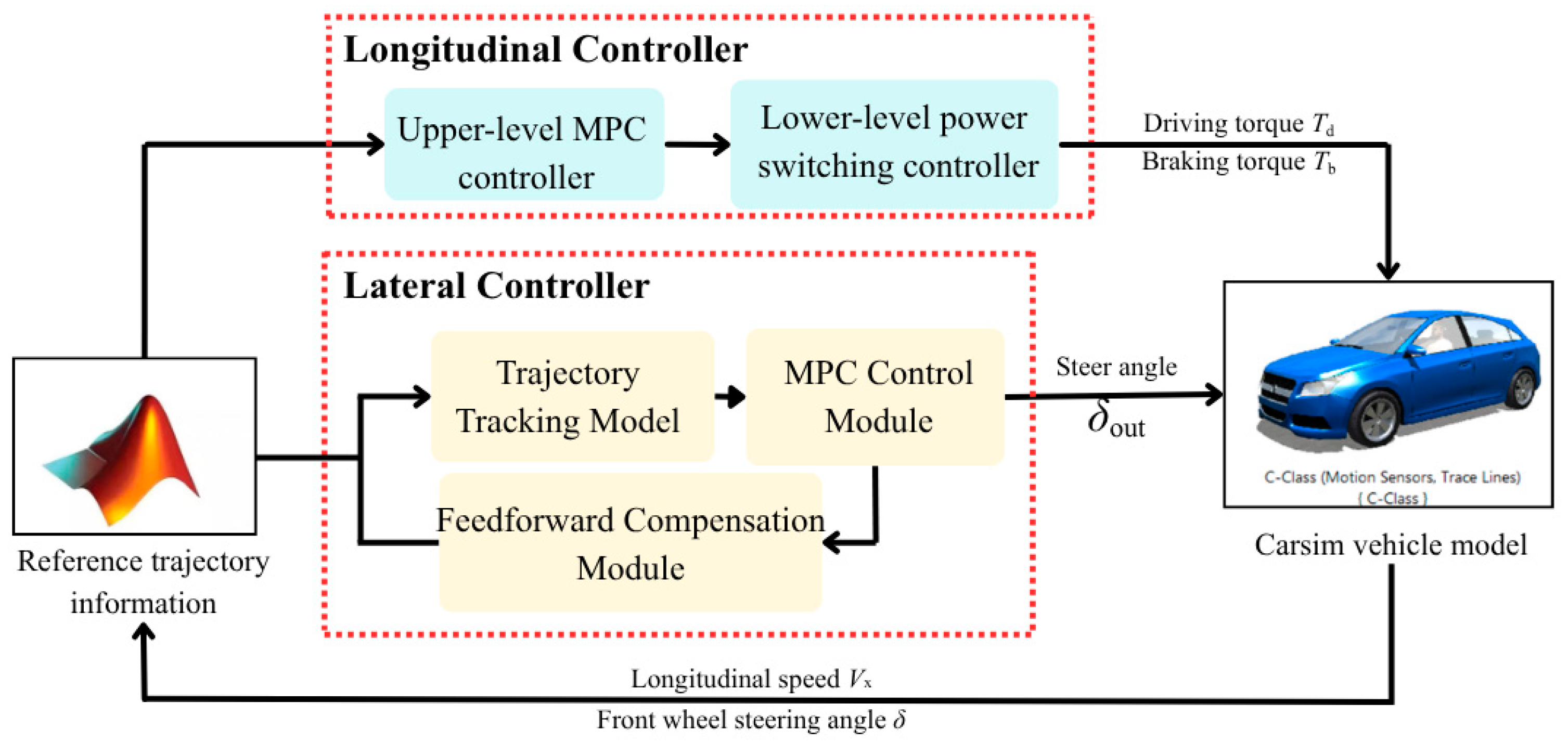
For the reference trajectory obtained by the above-mentioned method of introducing a single time variable, this study adopted the model predictive control (MPC) method. By performing rolling optimization in the prediction time domain, it can simultaneously handle multi-objective problems such as lateral position and heading errors, longitudinal velocity errors, and acceleration smoothness while explicitly considering acceleration constraints and longitudinal safety distance constraints. In terms of lateral control, the controller predicted and optimized the lateral displacement and heading of the vehicle based on the model, and it introduced a feedforward compensator to improve response speed and trajectory smoothness. In terms of longitudinal control, the augmented integral model was used to predict and optimize longitudinal velocity and acceleration, achieving continuous acceleration and deceleration to maintain ride comfort. In addition, the controller dynamically adjusted the weights during the optimization process to enable precise tracking at low speeds and smooth response during fast lane changes, thereby achieving lateral and longitudinal decoupling and collaborative control (Figure 1).

3.1. Lateral Controller Design

3.1.1. Lateral Error Calculation Model

Lateral error is a key state variable in trajectory tracking, representing the geometric deviation from the reference path. To balance computational efficiency and real-time performance, a geometric projection-based error model was adopted, which avoided curvature integration, ensured numerical stability, and offered superior real-time performance compared to Frenet coordinates [19,20,21]. Assuming the current position of the vehicle is P = (X, Y), the reference trajectory point is Pr = (Xr, Yr), and its corresponding heading angle is ϕr. The lateral error of the vehicle ed is defined as Equation (16).
e d = n r T P P r
where the expression of normal vector nr is given as Equation (17).
n r = sin ϕ r cos ϕ r
The heading error adopting a periodic differential angle is given as Equation (18).
e ϕ = atan 2 sin ϕ ϕ r ,   cos ϕ ϕ r
To obtain smoother error derivatives, exponential filtering is introduced to the discrete differential signal in the simulation, as shown in Formulas (19)–(21):
e d . ( k ) = α e d ( k ) e d ( k 1 ) T s + ( 1 α ) e d . ( k 1 )
e ϕ . ( k ) = α e ϕ ( k ) e ϕ ( k 1 ) T s + ( 1 α ) e ϕ . ( k 1 )
α = 0.3 + 0.4 min 1 , V x 15
This strategy improved smoothness at low speeds to suppress error oscillations and enhances response sensitivity at high speeds, thus balancing steady-state accuracy and dynamic performance.

3.1.2. Model Predictive Controller

Bulleted lists looked like: Model predictive control (MPC) is an effective means of achieving multi constraint and multi-objective coordinated control by solving future control sequences through rolling optimization. Previous studies have shown that compared with PID and LQR methods, MPC can show better dynamic performance and stability in autonomous driving trajectory tracking [22].
This article adopted a linearized lateral dynamics form based on the monorail model.
x = e d e ˙ d e ϕ e ˙ ϕ , u = δ
where ed is the lateral error, ed is the lateral velocity error, eϕ is the heading angle error, eϕ is the heading angular velocity error, and δ is the front wheel steering angle.
Based on the assumption of small angle and steady state, the linearized monorail model can be expressed as Equation (23).
x k + 1 = A c x k + B c u
The continuous system matrix is given as Equations (24) and (25).
A c = 0 1 0 0 0 2 C a f + C a r m V x m 2 L 2 C a r L 1 C a f m V x 0 0 0 1 0 2 L 2 C a r L 1 C a f I z V x 2 L 2 C a r L 1 C a f I z 2 L 1 2 C a f + L 2 2 C a r I z V x
B c = 0 2 C a f m 0 2 L 1 C a f I z
where m is the vehicle mass, Iz is the yaw moment of inertia, L1 and L2 are the front and rear wheelbase, Caf and Car are the front and rear wheel lateral stiffness, and Vx is the longitudinal velocity.
After discretization, the system state prediction model can be expressed as Equation (26).
x k + 1 = e A c Δ t x k + 0 Δ t e A c t B c t Δ δ k
Based on the predictive model, the optimization objective is given as Equation (27).
J = i = 1 N p x k + i | k T Q x k + i | k + j = 0 N c 1 Δ δ k + j T R Δ δ k + j
where Q is the state error weight matrix, R is the control variable weight matrix, Np is the predicted time domain length, and Nc is the control time domain length. To improve the adaptability of the controller at different speeds, a speed correction factor (Equation (28)) was introduced.
Q = Q α ( V x ) , R = R α ( V x )
This was calculated to achieve dynamic adjustment of weighting coefficients with vehicle speed [23]. This adaptive weighting strategy can improve control accuracy under low-speed conditions and enhance smoothness under high-speed conditions.
The control input was physically constrained and embedded in a linear form in a quadratic programming problem through a built-in optimization solver [24]. The corresponding expression is given as Equation (29).
min Δ U 1 2 Δ U T H Δ U + f T Δ U   s . t .   A ineq Δ U b ineq
where H and f are the Hessian and gradient vectors of the cost function, respectively, constructed by Q and R matrices.
When the optimizer failed to converge normally under specific operating conditions and lost its dynamic adjustment capability, the controller automatically switched to PID mode to realize optimization-feedback hybrid control, thereby improving the continuity and stability of the system with the “optimization-feedback hybrid” fault-tolerant mechanism.

3.1.3. Feedforward Compensator Design

The steady-state yaw mechanics model can effectively reduce the dynamic lag of vehicles and improve the smoothness of path tracking [25]. In order to improve the foresight of the response, this paper introduced curvature feedforward compensation based on steady-state yaw mechanic’s model. When the vehicle was turning steadily, the lateral forces of the front and rear wheels satisfied a balance relationship according to Equation (30).
C a f δ β L 1 r ˙ V x + C a r β + L 2 r ˙ V x = m V x r + β ˙
Based on the assumptions of small angle and steady state, the required front wheel steering angle for steady state can be derived according to Equation (31).
δ ff = m V x 2 L 1 C a f + L 2 C a r C a f L k
where κ is the curvature of the road. In order to enhance the adaptability of feedforward control at different vehicle speeds, this paper introduced speed adaptive gain according to Equation (32).
K ff ( V x ) = 0.5 , V x < 3 1.0 , 3 V x 20 1.2 , V x > 20
The final corner output is given as Equation (33).
δ out = K ff ( V x ) δ ff
This design can suppress excessive steering at low speeds and apply angle compensation in advance at high speeds, thereby reducing lateral response lag. The feedforward gain Kff(Vx) was optimized through multiple simulation tests. This gain was set in the form of a piecewise function to accommodate different longitudinal velocities.

3.2. Longitudinal Controller Design

Previous studies have shown that using a model predictive control framework for longitudinal velocity control can effectively balance acceleration smoothness and constraint handling capabilities while ensuring real-time performance [26,27]. This article designs a longitudinal controller under a unified MPC framework to achieve minimum velocity error and continuous acceleration control.

3.2.1. State Modeling

The longitudinal dynamics of a vehicle can be approximated as an integral model under simplified conditions according to Equation (34).
V k + 1 = V k + T   a k
To describe the continuity of acceleration changes, an augmented state was introduced.
x k = V k , a k 1 T
We defined ak = ak−1 + Δak, then the discrete system can be expressed in linear integral form according to Equation (36).
x k + 1 = 1 T 0 1 x k + T 1 Δ a k
where T is the sampling period. Based on the predictive model, the speed error was defined as Equation (37).
e v , k + i | k = V k + i | k V ref , k + i
Optimization objective is given as Equation (38).
J = i = 1 N p e v , k + i | k 2 Q v + j = 0 N c 1 Δ a k + j 2 R a
where Qv and Ra are the weighted matrices of speed error and control smoothness, respectively. The first term is used to penalize speed error, and the second term is used to suppress sudden acceleration changes.
To ensure ride comfort and power feasibility, acceleration constraints were applied to limit the longitudinal acceleration amplitude and acceleration change rate, respectively. The quadratic programming (QP) principle obtained by constraint solving was the same as Formula (34). This MPC design can explicitly handle longitudinal physical constraints, achieving dual objective coordination of speed tracking and comfort.

3.2.2. Lower-Level Actuator Switching Logic

Based on the energy balance and sliding priority strategy in reference [28], this paper improved the longitudinal MPC output characteristics. The expected acceleration areq output by MPC was converted into corresponding driving or braking torque through the actuator layer model, making the transition between sliding and driving smoother. The sliding priority strategy was designed to coordinate the longitudinal and lateral control allocation. It ensured the trajectory tracking stability under the MPC optimization framework, and its effectiveness was verified by co-simulation results.
According to the longitudinal dynamic balance relationship of the vehicle, it can be concluded according to Equation (39).
F res = m g f + 0.5 ρ C d A f V x 2 + m g sin θ
Among them, m is the curb weight of the car, g is the acceleration due to gravity, f is the rolling resistance coefficient, ρ is the air density, Cd is the air resistance coefficient, Af is the windward area of the car, Vx is the longitudinal speed of the car, and θ is the road slope angle. The natural sliding acceleration is defined as at = −Fres/m. The system determined whether the vehicle should be in driving, braking, or coasting mode based on the balance between expected acceleration and current resistance. The execution logic is given as Equation (40).
a req > a t + Δ a Driving   Mode a req < a t Δ a Braking   Mode | a req a t | Δ a Coasting   Mode
This logic implemented a sliding priority strategy through energy balance, allowing for the controller to actively release the driving force output under low load conditions, achieving conflict free switching between driving and sliding.

4. Simulation Verification

To validate the proposed dynamic trajectory generation method optimized for lane-changing time as well as the effectiveness of the MPC trajectory tracking control strategy, this paper conducted simulation studies from two aspects: the analysis of trajectory feasibility with lane-changing time optimization and the vehicle dynamics tracking control.

4.1. Feasibility Verification of Trajectory Planning

The simulation parameters are shown in Table 1. The lateral motion was modeled by a fifth-order polynomial to ensure smooth position, velocity, and acceleration profiles, enabling continuous curvature and natural heading variation during lane changes. The longitudinal motion adopted a segmented quadratic acceleration model to ensure smooth transitions and avoid abrupt acceleration, thereby enhancing vehicle stability. The corresponding simulation results are shown in Figure 2.
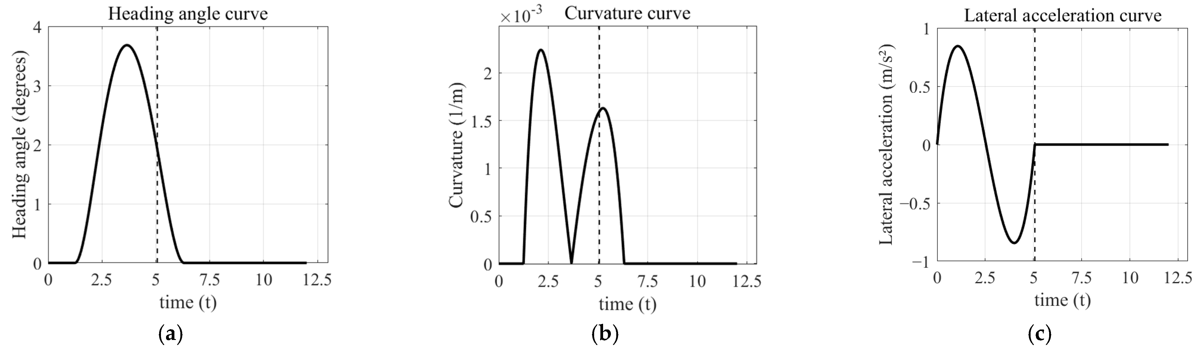
From the analysis of Figure 2, it can be concluded that under the optimal lane-changing time, the lateral acceleration exhibits a typical “S”-shaped variation, with a peak value far below the comfort limit, and no local overshoot or high-frequency oscillation occurs. The heading angle first rises and then falls back, corresponding to the “lane-change return” stage. The curvature curve exhibits a symmetrical bimodal structure, corresponding to two turning actions of entering and exiting the lane change, with small peak values and a gentle rate of change. The above results indicate that the proposed method can ensure continuous differentiability, smooth curvature, and stable posture at the trajectory level and has good ride comfort and dynamic feasibility.
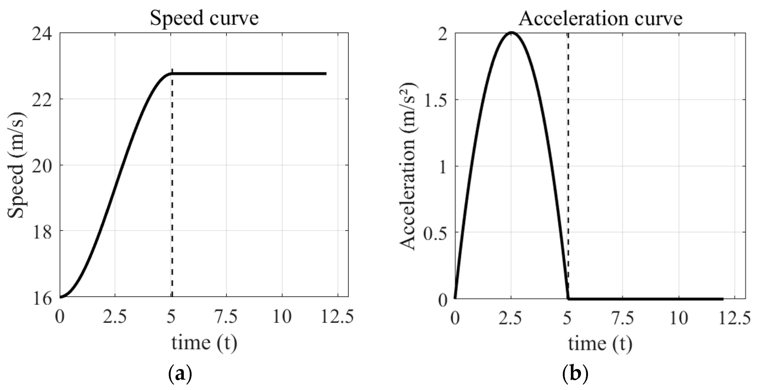
From Figure 3, it can be seen that the longitudinal speed reaches its maximum value at the end of the lane change, an increase of about 42% compared to the initial value, indicating that the proposed model balances overtaking efficiency and acceleration requirements. The speed curve is smooth without any jumps; the peak acceleration does not exceed the limit and gradually decays to zero, finally entering the steady-state uniform speed stage. The overall longitudinal dynamic constraints are satisfied, indicating that this method can complete the necessary acceleration and overtaking actions during lane changing.
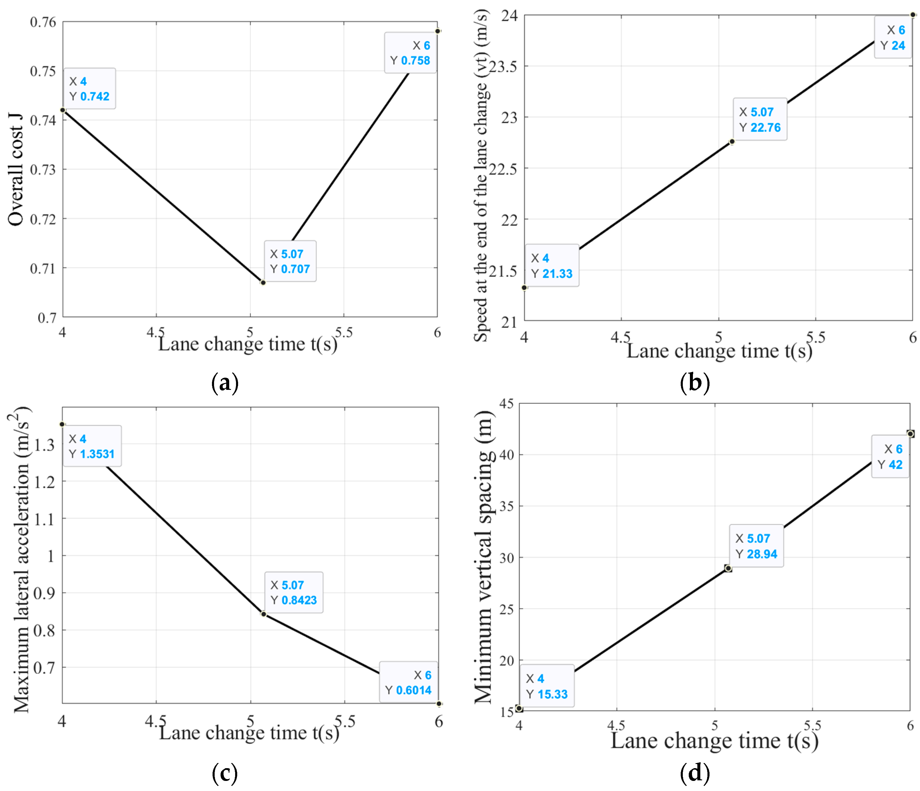
On this basis, lane-change time T is further introduced as a key decision variable. By performing a scan analysis on longitudinal speed, lateral acceleration, safe distance, and the comprehensive cost function, the impact of T on comfort, safety, and time efficiency is quantitatively assessed. The simulation results are shown in Figure 4.
Shorter lane-change times increase lateral jerk and reduce safety margins, while longer times impair efficiency. The dual-weight cost function (Figure 4a) yields an optimal time that balances comfort and safety. Compared to aggressive or gentle maneuvers, this optimum provides the smoothest lateral acceleration (Figure 4c), improved safety margins (Figure 4d), and a smooth velocity profile (Figure 4b), achieving stable lateral–longitudinal coupling and an effective compromise between safety and efficiency.
In summary, the proposed method not only meets the geometric and dynamic feasibility requirements at the trajectory level but also has attainability in the time dimension. By introducing time parameters, it enables the lane-changing strategy to achieve adjustable, analyzable, and interpretable performance trade-offs, providing an engineering-feasible parametric design framework for intelligent driving lane-changing decisions.

4.2. Trajectory Tracking Simulation Analysis

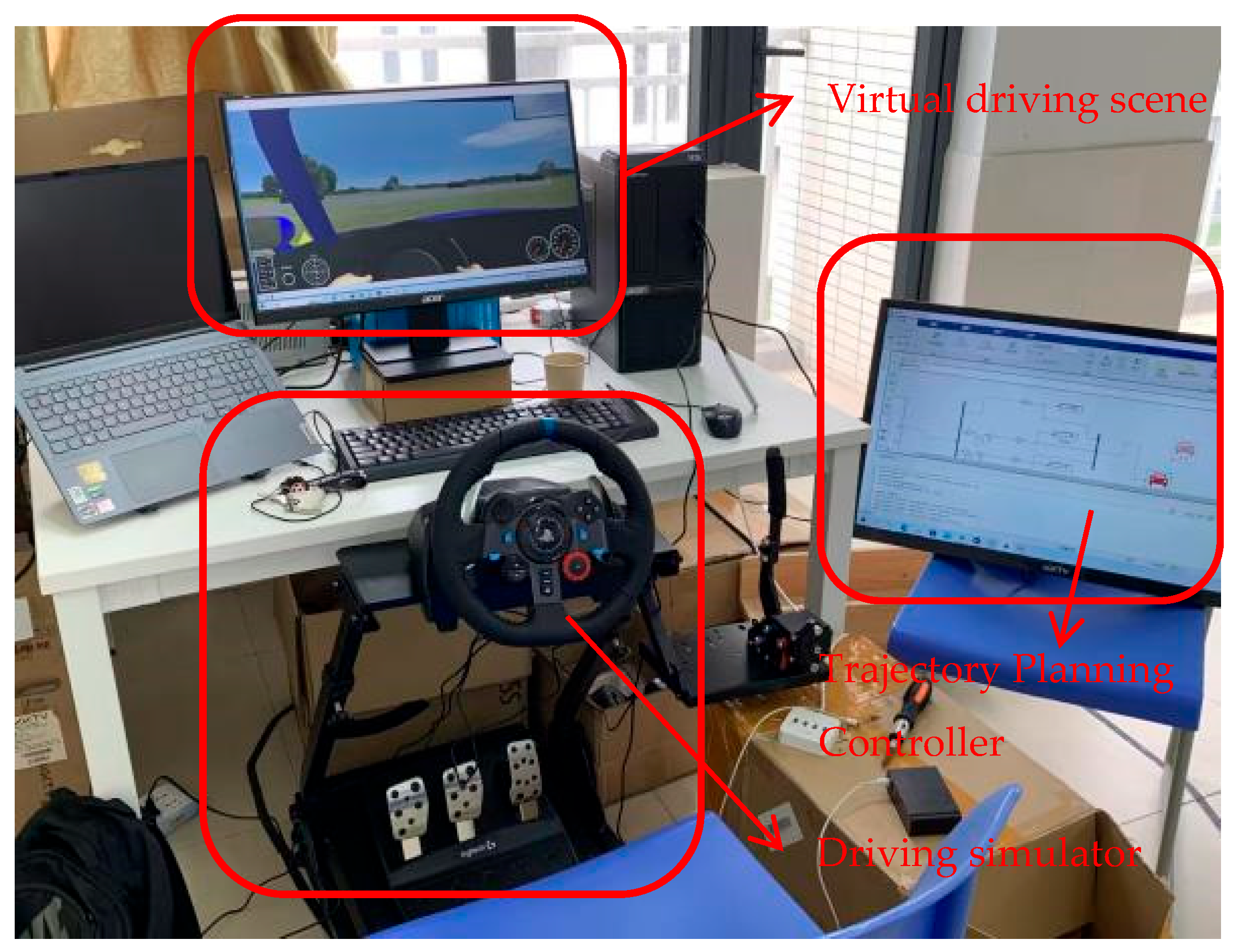
To verify the trajectory tracking performance of the designed MPC controller in complex lane-changing overtaking scenarios, this study conducted experiments based on the CarSim Simulink joint simulation platform (Figure 5). In the simulation, the C-Class Hatchback vehicle provided by CarSim 2022 was selected, with its initial position set to (0, 0) and an initial heading angle of 0 rad.
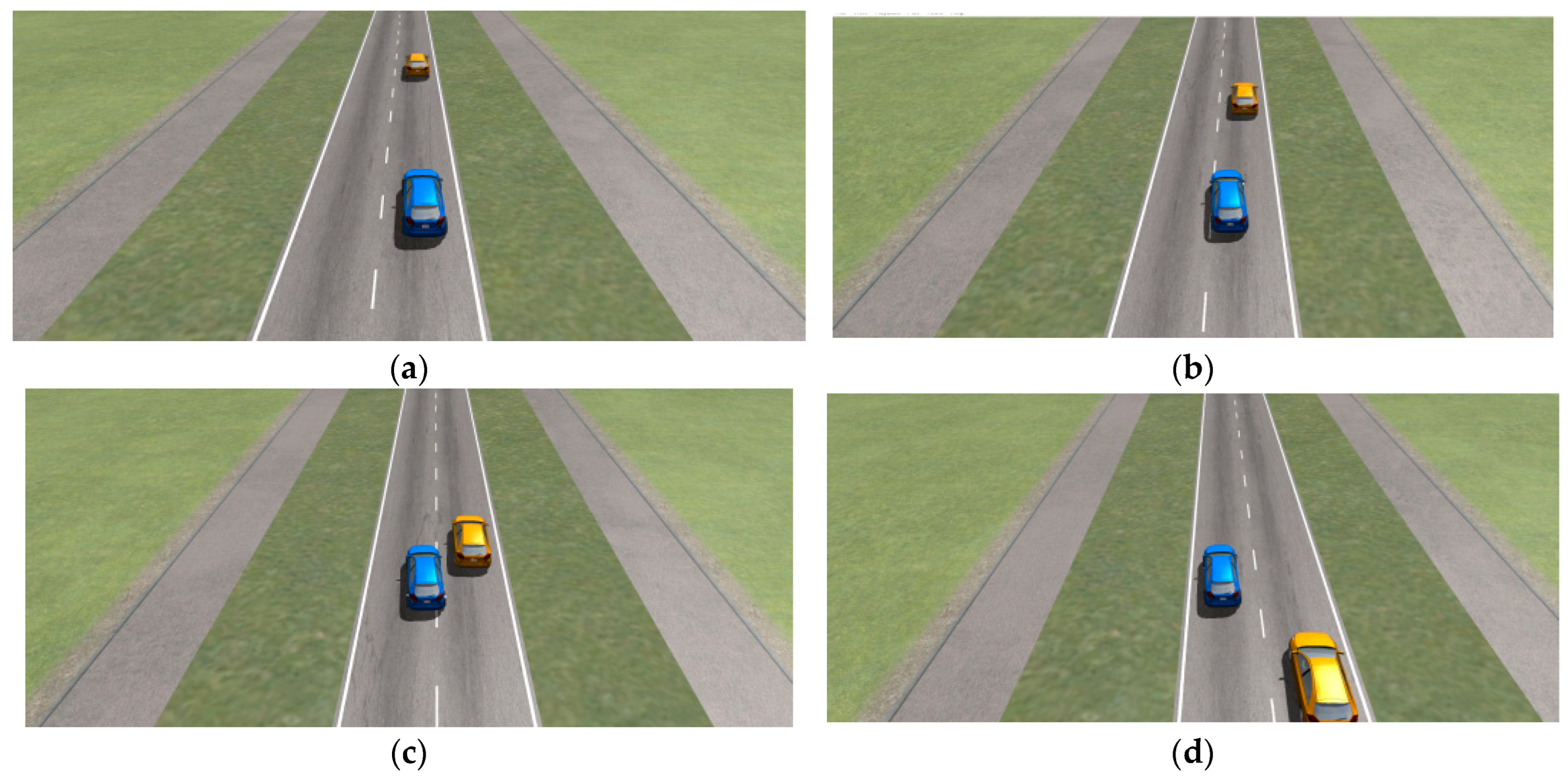
In autonomous driving trajectory tracking, the controller must not only ensure that the vehicle runs along the planned trajectory, but also achieve safe, smooth, and comfortable control under multiple constraints. Taking lane changing and overtaking as an example (Figure 6), the system needs to coordinate lateral and longitudinal control; comprehensively consider vehicle dynamics, acceleration constraints, and ride comfort; and combine this with predictive information about the road and surrounding vehicles to maintain a safe distance and ensure stability and safety throughout the entire process. Unlike traditional PID or LQR controllers, MPC can predict the future dynamics of the system and optimize the control sequence online while explicitly satisfying state and control variable constraints. Therefore, it has strong adaptability under complex dynamic conditions such as lane changes and overtaking.
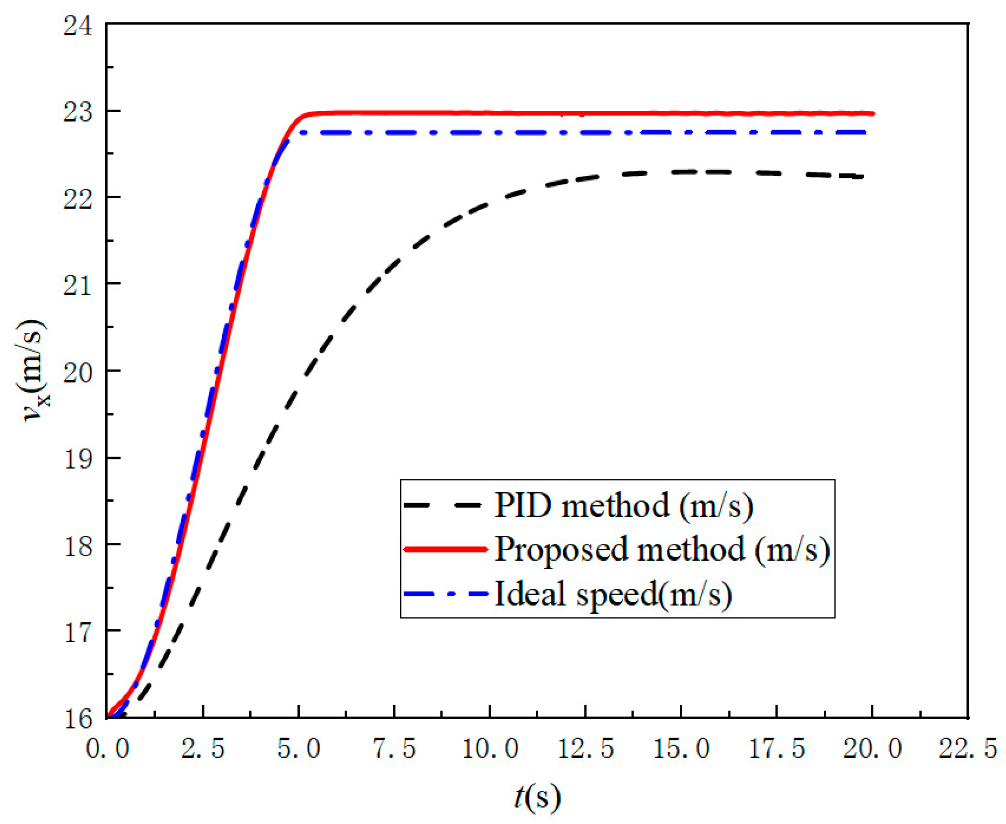
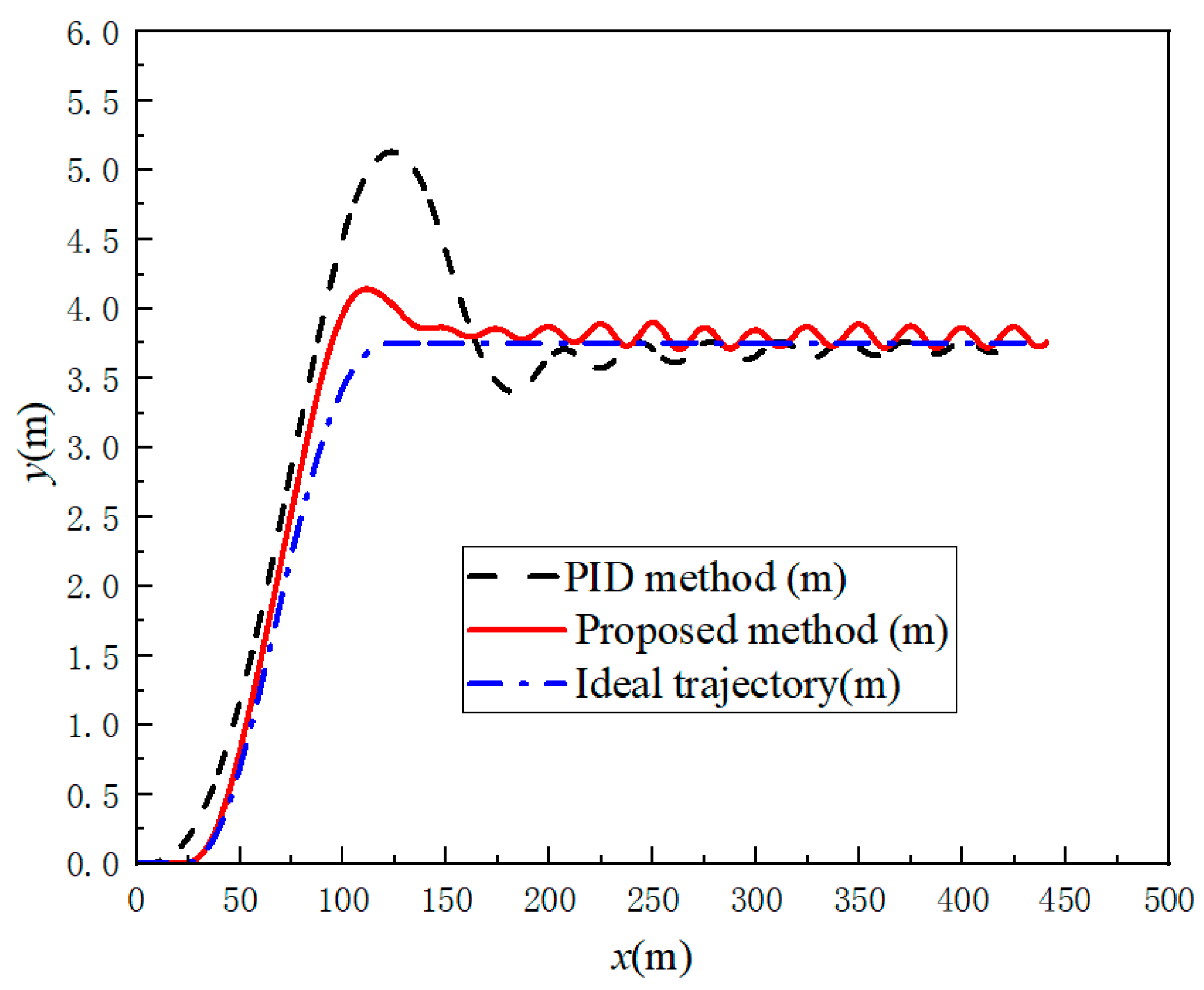
Figure 7 compares the proposed method, PID control, and the ideal trajectory. The proposed method closely tracks the reference with fast response, high accuracy, and minimal steady-state error, while PID exhibits noticeable lag, larger deviations, and persistent oscillations. Moreover, the proposed method achieves smaller overshoot, faster convergence, and improved stability, demonstrating superior dynamic and tracking performance over PID. Figure 8 presents the longitudinal speed profiles of the proposed method, the ideal reference, and PID control. The proposed method achieves smooth acceleration from 16 m/s to 23 m/s with close tracking and minimal fluctuations, while PID exhibits larger errors and noticeable oscillations. Additionally, the proposed method ensures faster convergence and superior steady-state stability, demonstrating improved tracking accuracy and smoothness over PID.
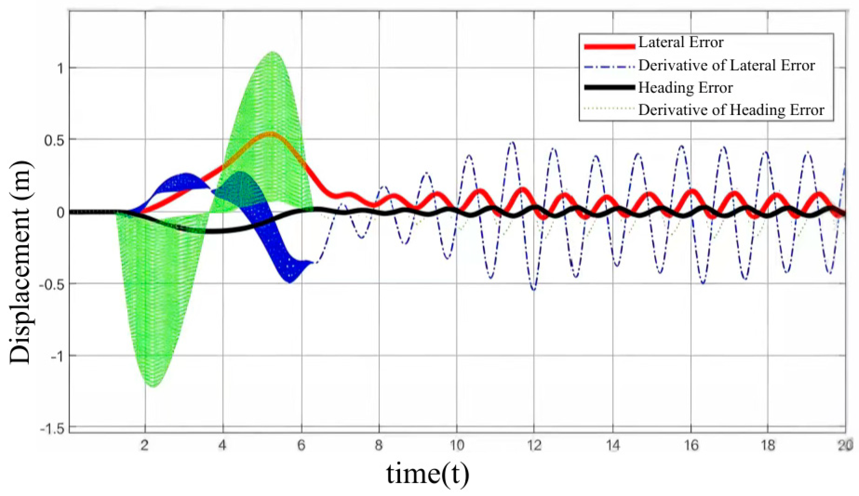
Figure 9 illustrates the evolution of lateral, yaw angle, and curvature errors during lane changing. Initial transient fluctuations arise from trajectory geometry variations and vehicle dynamics, while lateral and yaw errors remain small, indicating effective suppression of deviation. All errors rapidly converge to near zero with minimal oscillation, demonstrating that the MPC controller achieves smooth, robust, and high-precision trajectory tracking under high-speed conditions.
The comprehensive simulation results show that the designed MPC controller can achieve high-precision trajectory tracking under complex lane-changing overtaking conditions, with smooth vehicle motion, stable posture, and controllable longitudinal and transverse deviations. The ride comfort and safety are guaranteed, fully verifying the feasibility and reliability of the control strategy.

5. Discussion

5.1. Interpretation of Results

The simulation results demonstrate that the proposed method successfully balances safety, comfort, and efficiency. Lateral acceleration follows a smooth profile with a peak value below the comfort limit thanks to the quintic polynomial that enforces zero acceleration at both endpoints. The symmetric curvature curve corresponds to the entry and exit steering actions during lane changing.
Longitudinally, the vehicle accelerates smoothly without jerk-induced discomfort, as the quadratic acceleration model ensures gradual growth and decay of acceleration. The time-segment scan analysis reveals a clear trade-off: shorter lane-change time increases lateral jerk and reduces safety margins, while longer lane-change time impairs efficiency. The dual-weight cost function identifies an optimal time that balances these competing objectives.
The MPC-based controller tracks the planned trajectory with high accuracy, with lateral, yaw, and curvature errors converging rapidly to near zero. Compared to PID, the proposed controller exhibits faster response, smaller overshoot, and better stability, benefiting from predictive action and feedforward compensation.

5.2. Comparison with Existing Methods

Compared to pure analytical methods, the proposed method retains computational simplicity while explicitly incorporating dynamic constraints. Compared to sampling-based methods, it guarantees higher-order continuity essential for ride comfort at highway speeds. Compared to full optimization methods, the univariate approach significantly reduces computational cost, making it more suitable for real-time applications. Relative to the Frenet-frame approach, the present method introduces speed-adaptive weighting and a fault-tolerance mechanism for additional robustness.

5.3. Limitations and Open Questions

This study has several inherent limitations. First, validation is limited to simulation-based lane-changing and overtaking scenarios on straight roads, without incorporating sensor noise, actuator dynamic characteristics, perception uncertainty, complex curved road conditions, or multi-vehicle interactive driving scenarios. Second, the current work adopts linear tire simplification and an ideal perception assumption, while hardware-in-the-loop verification and real-vehicle experimental tests have not been implemented. Furthermore, this paper primarily concentrates on constructing a lightweight trajectory planning and lateral–longitudinal decoupled MPC tracking framework; extensive comparative evaluations with state-of-the-art approaches, including Frenet-based planning and nonlinear MPC methods, are not performed at this stage. In addition, in-depth research on tire friction ellipse constraints, TTC safety constraints, computational efficiency benchmarking, and quantitative robustness verification is not fully explored herein. Future research will address the above limitations by conducting embedded hardware testing, analyzing sensitivity to perception errors, developing learning-based adaptive weight adjustment strategies, designing uncertainty-aware MPC algorithms, extending the framework to multi-vehicle interactive scenarios, and completing further validation via hardware-in-the-loop platforms and real-road vehicle experiments.

6. Conclusions

This paper proposed a lateral–longitudinal decoupled dynamic trajectory planning method for lane-changing scenarios, using lane-change time as the sole optimization variable to balance comfort and efficiency, combined with an MPC-based tracking controller. The co-simulation results verified that the proposed method generates smooth, dynamically feasible trajectories while satisfying safety constraints. Future work will extend the method to multi-vehicle interactive scenarios and validate it on hardware-in-the-loop platforms.

Author Contributions

H.L. contributed to the overall research framework and methodology of this paper; W.L. contributed to the methodology and simulation sections of this paper; X.L. contributed to the simulation and data processing sections of this paper; Y.X. contributed to the construction of the experimental platform and HIL simulation of this paper; J.L. contributed to the simulation and data analysis of this paper; H.X. contributed to the research framework and methodology of this paper; T.S. contributed to the methodology and simulation analysis of this paper. All authors have read and agreed to the published version of the manuscript.

Funding

This study was funded by the Guangzhou Science and Technology Planning Project (2023A04J0366) and Guangdong Polytechnic Normal University Young Talent Project (2021SDKYA089).

Data Availability Statement

The data used in this study were collected at Guangdong Polytechnic Normal University and are not publicly available due to institutional restrictions. However, they are available from the corresponding author upon reasonable request.

Acknowledgments

This study, from theoretical modeling and simulation experiments to paper writing, was entirely completed independently by the authors. No generative AI tools (including but not limited to ChatGPT (GPT-3.5), Microsoft Copilot (Win10), etc.) were used for content generation or writing assistance. All mathematical derivations, graphs, and textual expressions are original works by the authors. If the journal requires a formal GenAI usage statement, we are willing to submit one.

Conflicts of Interest

Authors Yusheng Xiang and Jingxiang Li were employed by the company Suzhou Shangliwei Technology Co. and South China University of Technology. The remaining authors declare that the research was conducted in the absence of any commercial or financial relationships that could be construed as a potential conflict of interest.

References

  1. Huo, F.; Zhu, S.; Dong, H.; Ren, W. A new approach to smooth path planning of Ackerman mobile robot based on improved ACO algorithm and B-spline curve. Robot. Auton. Syst. 2024, 175, 104655. [Google Scholar] [CrossRef]
  2. Duraklı, Z.; Nabiyev, V. A new approach based on Bezier curves to solve path planning problems for mobile robots. J. Comput. Sci. 2022, 58, 101540. [Google Scholar] [CrossRef]
  3. Li, B.; Kong, Q.; Zhang, Y.; Shao, Z.; Wang, Y.; Peng, X.; Yan, D. On-road trajectory planning with spatio-temporal RRT* and always-feasible quadratic program. In Proceedings of the 2020 IEEE 16th International Conference on Automation Science and Engineering (CASE), Hong Kong, China, 20–21 August 2020; IEEE: New York, NY, USA, 2020; pp. 942–947. [Google Scholar] [CrossRef]
  4. Dasiah, N.B. Modified RRT* for Path Planning in Autonomous Driving. arXiv 2024, arXiv:2402.12129. [Google Scholar] [CrossRef]
  5. Liu, Y.; Cui, D. Application of optimal control method to path tracking problem of vehicle. SAE Int. J. Veh. Dyn. Stab. NVH 2019, 3, 209–219. [Google Scholar] [CrossRef]
  6. Wang, H.; Liu, B.; Ping, X.; An, Q. Path tracking control for autonomous vehicles based on an improved MPC. IEEE Access 2019, 7, 161064–161073. [Google Scholar] [CrossRef]
  7. Li, Y.; Yang, W.; Zhang, X.; Kang, X.; Li, M. Research on automatic driving trajectory planning and tracking control based on improvement of the artificial potential field method. Sustainability 2022, 14, 12131. [Google Scholar] [CrossRef]
  8. Gritschneder, F.; Graichen, K.; Dietmayer, K. Fast trajectory planning for automated vehicles using gradient-based nonlinear model predictive control. In Proceedings of the 2018 IEEE/RSJ International Conference on Intelligent Robots and Systems (IROS), Madrid, Spain, 1–5 October 2018; IEEE: New York, NY, USA, 2018; pp. 7369–7374. [Google Scholar] [CrossRef]
  9. Werling, M.; Ziegler, J.; Kammel, S.; Thrun, S. Optimal trajectory generation for dynamic street scenarios in a frenet frame. In Proceedings of the 2010 IEEE International Conference on Robotics and Automation, Anchorage, AK, USA, 3–7 May 2010; IEEE: New York, NY, USA, 2010; pp. 987–993. [Google Scholar] [CrossRef]
  10. Zhao, W.; Liu, H.; Lü, J.; Gao, Q.; Feng, G. Data-driven optimal formation control for multiple nonlinear quadrotors with switching topologies. IEEE Trans. Veh. Technol. 2023, 74, 2538–2548. [Google Scholar] [CrossRef]
  11. Krishnan, S.G.; Kumar, P.S.; Matara, N.N.; Wang, Y. Real-time experimental evaluation and analysis of PID and MPC controllers using HIL setup for robust steering system of autonomous vehicles. IEEE Access 2024, 12, 74711–74723. [Google Scholar] [CrossRef]
  12. Bai, S.; Wang, Y.; Cheng, M.; Sun, X.; Xu, M. Analytical Sensitivity Matrix for Near-Optimal Solution to Elliptical Orbit Transfer. IEEE Trans. Aerosp. Electron. Syst. 2026, 62, 461–478. [Google Scholar] [CrossRef]
  13. Paparazzo, F.; Castoldi, A.; Imran, M.I.I.S.; Arrigoni, S.; Braghin, F. Learning-Based MPC Leveraging SINDy for Vehicle Dynamics Estimation. Electronics 2025, 14, 1935. [Google Scholar] [CrossRef]
  14. Cai, W.; Kordabad, A.B.; Esfahani, H.N.; Lekkas, A.M.; Gros, S. MPC-based reinforcement learning for a simplified freight mission of autonomous surface vehicles. In Proceedings of the 2021 60th IEEE Conference on Decision and Control (CDC), Austin, TX, USA, 14–17 December 2021; IEEE: New York, NY, USA, 2021; pp. 2990–2995. [Google Scholar] [CrossRef]
  15. Li, G.; Guo, H.; Wang, Z.; Wang, M. Online trajectory optimization for safe autonomous overtaking with active obstacle avoidance. Robot. Auton. Syst. 2023, 169, 104528. [Google Scholar] [CrossRef]
  16. Jun, J.; Guensler, R.; Ogle, J. Smoothing methods designed to minimize the impact of GPS random error on travel distance, speed, and acceleration profile estimates. Transp. Res. Rec. 2006, 1972, 141–150. [Google Scholar] [CrossRef]
  17. Li, Y.; Li, L.; Ni, D. Dynamic trajectory planning for automated lane changing using the quintic polynomial curve. J. Adv. Transp. 2023, 2023, 6926304. [Google Scholar] [CrossRef]
  18. Rabiee, P.; Hoagg, J.B. Soft-minimum and soft-maximum barrier functions for safety with actuation constraints. Automatica 2025, 171, 111921. [Google Scholar] [CrossRef]
  19. Huang, J.; He, Z.; Arakawa, Y.; Dawton, B. Trajectory planning in frenet frame via multi-objective optimization. IEEE Access 2023, 11, 70764–70777. [Google Scholar] [CrossRef]
  20. Kayacan, E.; Ramon, H.; Saeys, W. Robust trajectory tracking error model-based predictive control for unmanned ground vehicles. IEEE/ASME Trans. Mechatron. 2015, 21, 806–814. [Google Scholar] [CrossRef]
  21. Nan, J.; Shang, B.; Deng, W.; Ren, B.; Liu, Y. MPC-based path tracking control with forward compensation for autonomous driving. IFAC-Pap. 2021, 54, 443–448. [Google Scholar] [CrossRef]
  22. Stano, P.; Montanaro, U.; Tavernini, D.; Tufo, M.; Fiengo, G.; Novella, L.; Sorniotti, A. Model predictive path tracking control for automated road vehicles: A review. Annu. Rev. Control 2023, 55, 194–236. [Google Scholar] [CrossRef]
  23. Yang, S.; Qian, Y.; Hu, W.; Xu, J.; Sun, H. Adaptive MPC-based lateral path-tracking control for automatic vehicles. World Electr. Veh. J. 2024, 15, 95. [Google Scholar] [CrossRef]
  24. Bemporad, A. A quadratic programming algorithm based on nonnegative least squares with applications to embedded model predictive control. IEEE Trans. Autom. Control 2015, 61, 1111–1116. [Google Scholar] [CrossRef]
  25. Wei, W.; Li, L.; Li, Q.; Zhang, S.; Fan, C.; Liang, L. Dynamic Weight Model Predictive Control for Longitudinal Adaptive Cruise Systems in Electric Vehicles. Appl. Sci. 2025, 15, 6715. [Google Scholar] [CrossRef]
  26. Matute, J.A.; Marcano, M.; Zubizarreta, A.; Perez, J. Longitudinal model predictive control with comfortable speed planner. In Proceedings of the 2018 IEEE International Conference on Autonomous Robot Systems and Competitions (ICARSC), Torres Vedras, Portugal, 25–27 April 2018; IEEE: New York, NY, USA, 2018; pp. 60–64. [Google Scholar] [CrossRef]
  27. Guo, L.; Ge, P.; Sun, D.; Qiao, Y. Adaptive cruise control based on model predictive control with constraints softening. Appl. Sci. 2020, 10, 1635. [Google Scholar] [CrossRef]
  28. Hwang, H.S. Control strategy for optimal compromise between trip time and energy consumption in a high-speed railway. IEEE Trans. Syst. Man Cybern.-Part A Syst. Hum. 1998, 28, 791–802. [Google Scholar] [CrossRef]
Figure 1. Hierarchical controller structure diagram.
Machines 14 00619 g001
Figure 2. Comfort simulation results diagram: (a) heading angle curve; (b) curvature curve; (c) lateral acceleration curve. The dotted line denotes the moment when overtaking is completed.
Machines 14 00619 g002
Figure 3. Efficiency simulation results diagram: (a) speed curve; (b) acceleration curve. The dotted line denotes the moment when overtaking is completed.
Machines 14 00619 g003
Figure 4. Parameter sweep analysis of lane-change time: (a) double-weighted cost function; (b) time in vertical speed comparison; (c) time in comparison of lateral acceleration; (d) time comparison for lane-change completion distance.
Machines 14 00619 g004
Figure 5. Matlab/Carsim joint simulation platform.
Machines 14 00619 g005
Figure 6. CarSim simulation process diagram: (a) before overtaking; (b) while overtaking_1; (c) while overtaking_2; (d) after overtaking.
Machines 14 00619 g006
Figure 7. Trajectory tracking control chart.
Machines 14 00619 g007
Figure 8. Speed tracking comparison chart.
Machines 14 00619 g008
Figure 9. Tracking error convergence diagram.
Machines 14 00619 g009
Table 1. Simulation parameters.
Parameter NameSymbolDataUnit
Initial longitudinal velocity v 0 16m/s
Obstacle vehicle longitudinal speed v t 12m/s
Lane width W 3.75m
Maximum lateral acceleration limit m a x a y 3.0m/s2
Maximum longitudinal acceleration a m a x 2.0m/s2
Initial relative longitudinal distance s 0 30m
Weight coefficient w 1 , w 2 0.6, 0.4-
Total simulation timeT12s
Safety distance constraint d s a f e 3m
Disclaimer/Publisher’s Note: The statements, opinions and data contained in all publications are solely those of the individual author(s) and contributor(s) and not of MDPI and/or the editor(s). MDPI and/or the editor(s) disclaim responsibility for any injury to people or property resulting from any ideas, methods, instructions or products referred to in the content.