1. Introduction
1.1. Background
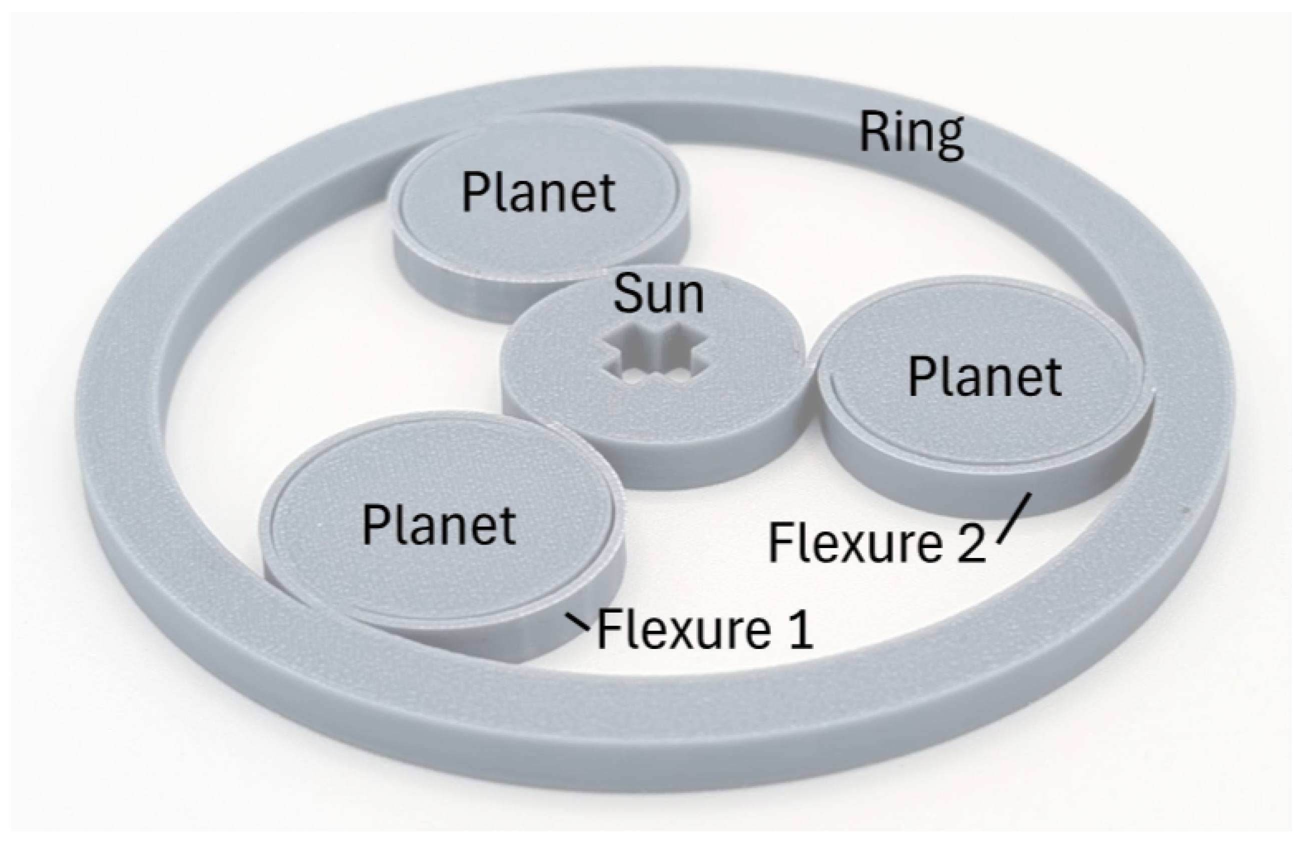
This paper investigates the CORE bearing (
Figure 1), a compliant torsional spring and bearing mechanism [
1]. Its ability to provide restorative torque with high radial stiffness and a large operating range of motion makes it a promising candidate as a parallel elastic element for parallel elastic actuator (PEA) prosthetic systems. Characterization of the bearing’s torque–deflection behavior and the relationship between fabrication method and radial stiffness provides useful information for determining how to tailor the bearing for a desired application. While full integration into a prosthetic system is beyond the scope of this project, this work is a necessary step toward evaluating the CORE bearing and its potential suitability as a PEA element.
Passive prosthetic devices, such as compliant foot–ankle systems, have historically dominated clinical use due to their reliability, low maintenance, and affordability [
2]. However, because passive prostheses cannot generate net positive work, their ability to replicate biological function is limited. Powered prostheses address the limitations of passive devices by actively generating joint torque, enabling improved adaptability across diverse environmental conditions. They are growing increasingly viable in both the domains of research and daily use for individuals with limb loss [
3,
4,
5]. The development of active prostheses has benefited from recent progress in motor miniaturization, battery efficiency, and control algorithms [
6,
7].
Series elastic actuators (SEAs) are well suited for actuation systems requiring force control and energy storage [
8,
9]. As a result, many active prostheses employ SEAs to minimize energy consumption [
10]. PEAs have emerged as an alternative approach, reducing motor torque requirements and improving energy efficiency [
11,
12,
13,
14]. By partially offloading actuator demands, PEAs enable smaller and lighter actuation systems, making them advantageous for prosthetic applications.
This work makes the following contributions:
Examines the strengths and limitations of multiple CORE bearing design variations, including monolithic, split-ring, split-sun, and multi-material designs.
Proposes alternative fabrication methods to mitigate the current manufacturing constraints related to kerf number.
Identifies nonlinear torque behavior in the CORE bearing via finite element analysis (FEA) and experimental testing that is not captured in the analytical model.
Presents a CORE bearing design optimization tool that returns the geometric parameters of a bearing with minimal planar area while satisfying a user-specified torque requirement.
Demonstrates the inverse relationship between radial stiffness and kerf by conducting tensile tests on assembled CORE bearings with a range of kerfs and shows that smaller kerf width leads to higher radial stiffness.
1.2. Related Work: Rolling-Contact Mechanisms
Rolling-contact mechanisms appeared in the literature in 1969 with the introduction of the Rolamite [
15], a device consisting of a flexible metal band wrapped in an S-shape around two cylindrical rollers, which are free to rotate and translate within a channel. A tensioned band constrains the rollers and provides low-friction linear guidance. Hillberry and Hall further developed the Rolamite concept into a mechanical joint, termed the “rolling-contact joint,” and described its primary intended application as a prosthetic knee [
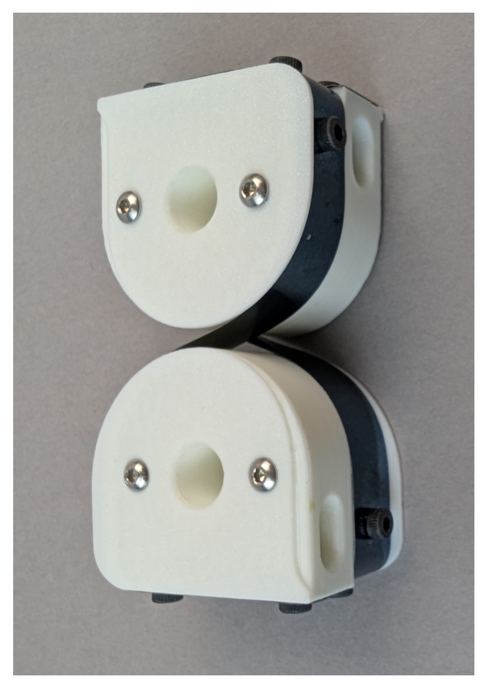
16]. An example of a rolling-contact joint is shown in
Figure 2. Due to rolling-contact joints’ high precision and no-slip condition, Jeanneau et al. [
17] and Cannon et al. [
18] independently developed compliant rolling-contact joint designs that can perform the functions of and serve as replacements for springs and limited-rotation bearings. Cannon et al. [
18] coined the term compliant rolling-contact element (CORE). Both these, and compliant rolling-contact architected materials (CRAMs), which function according to the same rolling-contact joint principle, have since been developed for applications including shape-morphing arrays [
19], spinal implants [
20], and multi-stable geometries [
21].
Cannon [
1] also arranged multiple COREs in a planar planetary-gear-like configuration to create the CORE bearing. A 3D-printed CORE bearing with each element labeled is shown in
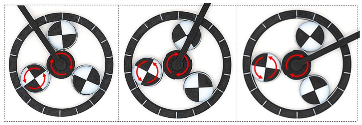
Figure 1. The CORE and CORE bearing share the same functional principle: each unit consists of a flexible member wrapped around two rotating bodies—a “sun” and a “planet”—with the radii of curvature determining both the bending stress in the flexure and the resulting torque response. As the planets rotate relative to the sun, the flexures bend and store strain energy, producing a torque that acts to restore the system to its neutral undeformed state. CORE bearing rotational motion is demonstrated in
Figure 3.
This compliant mechanism is described as a bearing because, similar to traditional bearings, it offers high radial stiffness while allowing a large range of rotational motion. Unlike traditional bearings, the CORE bearing generates a restorative torque of constant magnitude when displaced, permitting its function as a torsional spring. This class of mechanism is particularly relevant for robotic and powered prosthetic systems where reduced part count and multifunctional components enhance efficiency, reliability, and overall performance. Building on the original CORE bearing configurations introduced by Cannon [
1], this work proposes additional design variants that address the manufacturing limitations of prior implementations. It further presents experimental and FEA torque–deflection measurements and radial stiffness characterizations to facilitate improved understanding of the full benefits and limitations of this mechanism.
1.3. Theory
The analytical model in this paper originates from Cannon [
1] and is based on classical Euler–Bernoulli beam theory. Cannon applies this theory to the specific geometry of the CORE bearing, providing a framework for estimating maximum flexure stress and output torque, both of which are predicted to remain constant for the range of motion of the device. The relevant equations are summarized in this section. The model assumes a fixed ring and computes the total output torque applied to the sun during deflection.
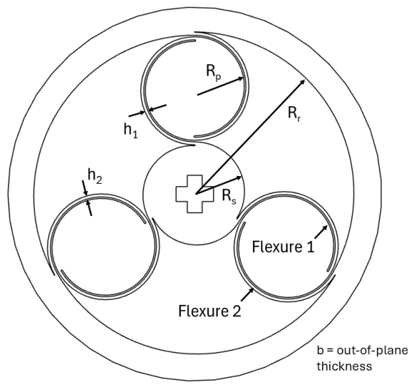
The performance of the CORE bearing is governed by the radii of the sun, planet, and ring, as well as the thickness and initial radii of the flexures and the out-of-plane thickness of the device (
Figure 4). Flexure Type 1 refers to the flexures connecting the sun to the planets. Flexure Type 2 refers to the flexures connecting the planets to the ring.
The maximum stress in the CORE bearing occurs in the flexures and is governed by the material modulus of elasticity (
E) and the geometric parameters flexure thickness (
h) and effective radius of curvature (
). The effective radius of curvature serves as an approximation of how tightly the flexures bend in their deformed state. It combines the flexure’s initial curvature and the curvature of the surface around which the flexure bends:
Type 1 flexures experience the highest stress due to curvature inversion as they transition from wrapping around the planets to curving in the opposite direction around the sun. For (
), the minimum radius of curvature encountered during assembly or operation is used.
Torque calculation for the CORE bearing begins by finding the effective radii of curvature of Type 1 and Type 2 flexures (
) when wrapped around the planets (Equations (
3) and (
4)):
As the CORE bearing rotates, Type 1 flexures begin to invert their curvature and bend around the sun. The effective radius of Type 1 flexures (
) when in contact with the sun is
In contrast, Type 2 flexures do not undergo curvature inversion upon contacting the ring; instead, their radius of curvature increases, resulting in lower stress levels than those experienced by Type 1 flexures. The effective radius of curvature of Type 2 flexures (
) in contact with the ring is
As the CORE bearing rotates, Type 1 flexures undergo curvature inversion, while Type 2 flexures experience an increase in curvature during contact with the sun and ring, respectively. Despite these differing deformation modes, both flexures generate a restoring torque on each planet due to their elastic deformation. The torque contributed by each flexure is given by
where
and
are the area moments of inertia for Type 1 and Type 2 flexures:
Each planet exerts a torque on the sun:
Multiplying by the number of planets returns the total predicted output torque of the CORE bearing at the sun for all angles:
The range of motion for this model depends on the number of planets, the lengths of the flexures, and/or the relative radii of the planets and sun. The models presented above assume (i) constant radii and (ii) no flexure overlap between neighbors. Under these assumptions, the maximum valid angular deflection is
where
and
represent the lengths of Type 1 and Type 2 flexures, respectively. The implication is that the maximum range of angular deflection where the model remains accurate is dictated by how far the planets can rotate before the flexures begin to overlap their neighbors, or by how far the planets can rotate before the entire length of the flexures is inverted along either the sun or the ring.
While it is physically possible to construct a bearing that permits overlap between flexures, once overlap occurs, the effective radius of the contact surface changes by an amount h at each interval of . To maintain the most accurate torque predictions in that regime requires a piecewise formulation that updates the radius at each overlap transition.
2. CORE Bearing Design
The following subsections discuss the monolithic and split-ring designs and fabrication methods introduced by Cannon [
1], outlining the advantages and disadvantages of each. Two novel bearing designs and fabrication methods are presented: split-sun and multi-material. These emerged by building upon the strengths of both original design configurations.
2.1. Monolithic Bearing
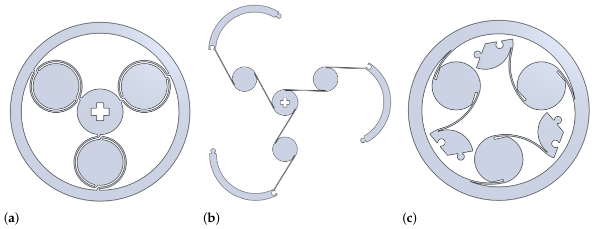
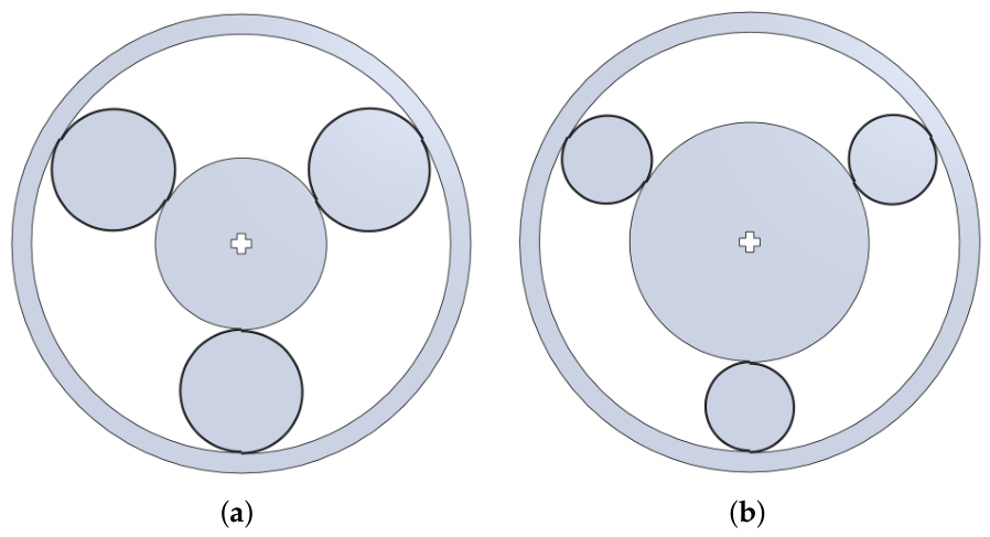
Monolithic CORE bearings are designed to be manufactured directly in their final functional configuration; no post-processing or assembly of the bearing is required. This results in a monolithic ring of uniform geometry that surrounds the sun and planets, minimizing net material area since the material footprint is exactly the size of the bearing. The flexures exist in a pre-curved geometry around the planets, with initial radii of curvature approximately equal to the planet radius plus the manufacturing kerf width. The designs shown in
Figure 1,
Figure 3,
Figure 4 and
Figure 5a exemplify monolithic CORE bearings.
Monolithic bearings also possess several disadvantages. First, there is poor contact between the flexures and planet/sun/ring surfaces due to the kerf width introduced by the manufacturing process. The kerf width creates some minimum clearance between the flexure elements and the circular elements about which they bend. That clearance enables the sun and planets to exhibit parasitic radial motion with minimal resistance, and the total magnitude of the radial motion away from the manufactured state is proportional to the kerf width.
For example, in fused deposition modeling (FDM) 3D printing, an equivalent kerf width can be described by the minimum clearance possible between printed lines before the plastic bonds across the gap. More traditional kerf widths include the tool diameter in computer numerical control (CNC) milling, the wire thickness in wire electrical discharge machining (wire EDM), laser width in a laser cutter, or photoscreen resolution in stereo-lithography apparatus (SLA) printing. Regardless of the manufacturing medium, the kerf width will always produce a gap in a monolithic CORE bearing.
A second disadvantage manifests itself in the flexure geometry. Since the flexures are manufactured pre-curved around the planets, Type 1 flexures must invert their original curvature as they bend around the sun during the mechanism’s rotation. As illustrated in Equation (
2), the stress in a flexible member depends on its effective radius of curvature. Equations (
3)–(
6) describe how to calculate this parameter for flexures on each geometry (sun, planet, or ring). The key observation is that, as the mechanism rotates, the curvature of each Type 1 flexure is inverted, leading to much higher stresses than if the flexures were manufactured straight.
2.2. Split-Ring Bearing
Split-ring bearings are manufactured in an expanded non-functional state where the ring is split into parts and the initial radii of curvature of the flexures do not necessarily adhere to the radii of curvature of the planets. To function properly, these CORE bearing designs must be assembled by connecting the parts of the ring. Once assembled, split-ring CORE bearings function the same as monolithic CORE bearings.
Figure 5b is an example of a split-ring CORE bearing before it has been put together.
The most apparent advantage of split-ring bearings is the constant contact between rolling elements. The improvement in surface contact, and thus radial stiffness, of the flexible members comes as a direct result of manufacturing the bearing in the split-ring state. Whereas the monolithic models are constrained by the kerf width of the manufacturing process as a result of machining the flexible members from the same vicinity as the planets, sun, and ring, the split-ring version separates these components during manufacture, enabling the proper bearing geometry to be produced once the mechanism is assembled.
Similarly, because the flexible members are not required to be manufactured with the same curvature as the planets, they are not subject to the consequences of inverted curvature present in the monolithic models. As such, they can experience more distributed stresses in both directions of curvature. However, a larger initial radius of curvature also reduces the torque output of the mechanism.
These models also have their respective disadvantages. The increased footprint when manufacturing a split-ring bearing from a planar sheet can lead to a large amount of wasted material because of the large areas of empty space in the design. This can be slightly mitigated by manufacturing multiple devices at once and interweaving each design with its neighbor on the workpiece. If large-scale manufacturing is desired, the additional time spent assembling each bearing would also lead to higher production costs and manpower requirements. Additionally, because this design requires a nonuniform outer ring, the ability of the ring to uniformly distribute radial loads is reduced and new failure points are introduced.
2.3. Split-Sun Bearing
The split-sun CORE bearing design combines the strengths of both monolithic and split-ring bearings while mitigating their respective drawbacks by dividing the sun into multiple pieces instead of the potentially load-bearing ring. As shown in
Figure 5c, it retains the continuous ring characteristic of the monolithic bearing while allowing the curved flexures to be manufactured away from the planets. These features together improve the radial stiffness of the ring while also eliminating the need for a kerf width distance between planets and flexures. Compared to an equally sized monolithic bearing, the split-sun design reduces flexure stress while maintaining a compact footprint and minimizing material waste. Additionally, it offers easier assembly than the split-ring design as all the components are constrained within the continuous ring. The minimum initial radius of curvature of each flexure is still constrained by the radii of the sun and planets; the flexures cannot be manufactured with a curvature smaller than the planetary surfaces they contact.
2.4. Multi-Material CORE Bearing
Bearings fabricated out of polymers exhibited inconsistent torque behavior across trials due to stress relaxation. Fabricating either the monolithic or split-ring bearings from materials not susceptible to creep or stress relaxation, e.g., metals, would require impractically large geometries approaching one meter to avoid flexure failure due to the manufacturing constraints on the minimum flexure thickness. From Equation (
7), it can be seen that the individual torque contributions of each flexure are proportional to their area moments of inertia and their effective radii of curvature. However, the stresses calculated using Equation (
2) are proportional to the thickness of each flexure and inversely proportional to the effective radii of curvature. As a result, the balance between the torque output and safety factor dictates the minimum flexure thickness and radii.
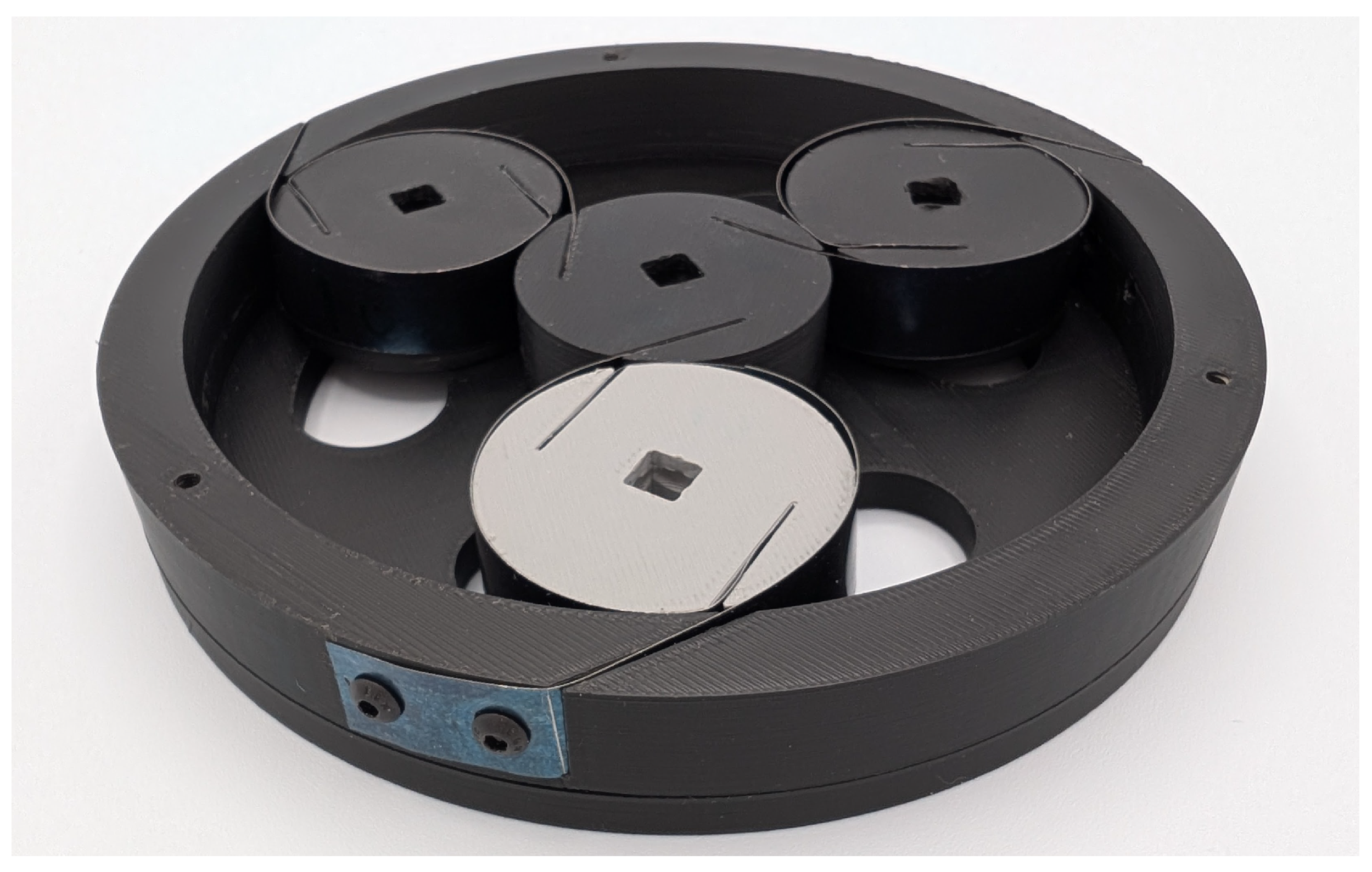
The multi-material CORE bearing shown in
Figure 6 was developed to improve the design flexibility that comes with combining materials with different costs, strengths, and manufacturing methods. In contrast to the monolithic, split-ring, and split-sun designs, which use the same continuous material for the ring, sun, planets, and flexures, the multi-material design makes different components from materials optimized for their function. The flexures, which rely on large elastic deflections, require materials with high compliance and a high yield strength–Young’s modulus ratio, such as polypropylene, polyethylene, Ti-13 titanium alloy, or 7075 aluminum. However, these materials are often expensive and over-qualified for the ring, sun, and planets, which ideally remain rigid during operation. Separating materials by function enables performance optimization while reducing overall cost. Flexures can be made from any material best suited to accommodate the desired deflection and torque behavior, while the ring, sun, and planets can be made of any affordable material strong enough to bear the expected radial loads experienced by the bearing.
To evaluate the performance and feasibility of the CORE bearing, four experiments were conducted: (1) characterization of torque response for a novel bearing design configuration, (2) finite element analysis, (3) optimization tool development, and (4) axial drift/radial stiffness evaluation.
3. Torque–Deflection Characterization
To validate that the multi-material CORE bearing conforms to the behavior predicted by the analytical model, torque testing was conducted on the prototype shown in
Figure 6 with the parameters given in
Table 1. In this prototype, the ring, sun, and planets are made of PLA and the attached flexures are strips of 1095 spring steel. The lengths of spring steel are connected to the ring, planets, and sun with M3 screws that interface with heated inserts embedded in the PLA. The spring steel attachment to the planets and sun is recessed in the PLA to prevent interference from the screw heads during rolling. The multi-material bearing can be made with initially straight flexures, as is typical for the split-ring bearing design, but mechanism assembly and function are facilitated by initially curling the spring steel flexures around the planets, similar to a monolithic bearing design. For the multi-material CORE bearing in
Figure 6, the spring steel strips were curled tightly around a small cylinder, resulting in initial radii of curvature of 16.9 mm for Type 1 flexures and 15.4 for Type 2 flexures (see
Table 1). This ensures that the flexures wrap snugly around the planets in the CORE bearing’s undeformed state.
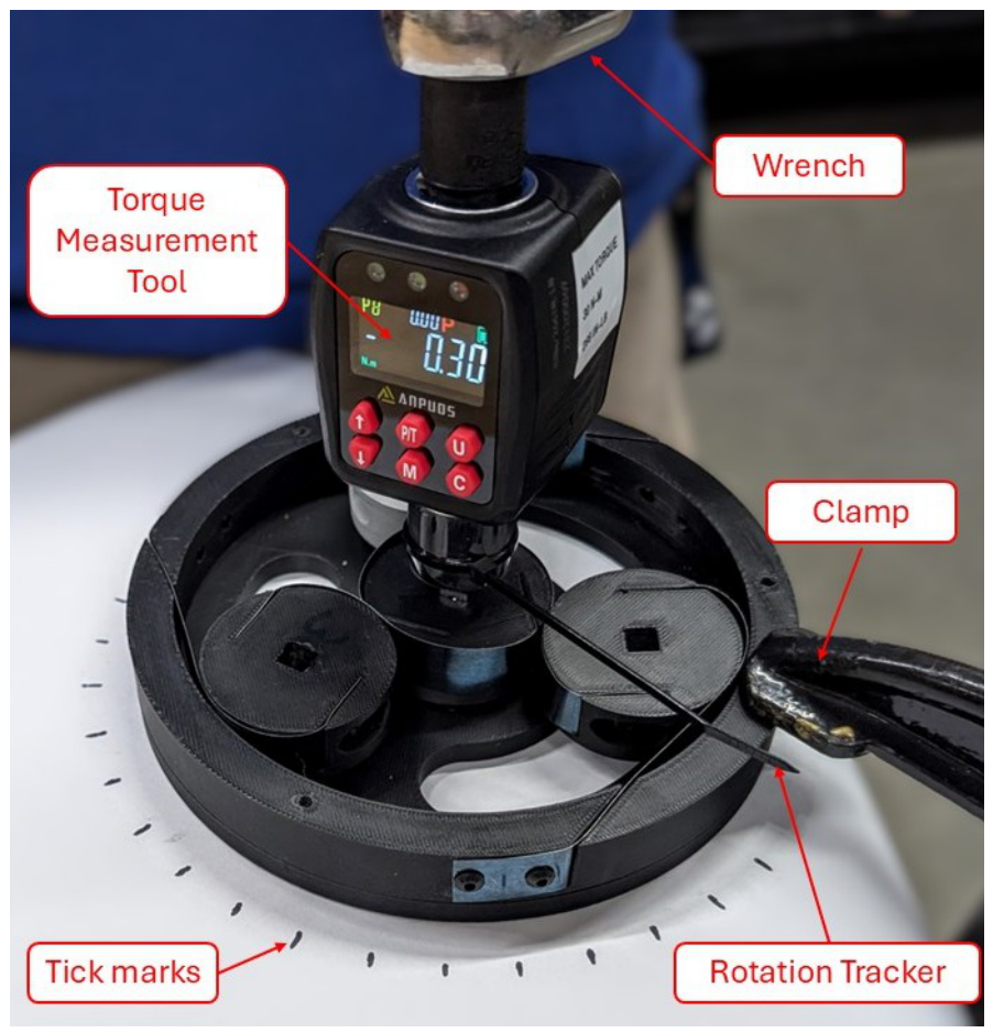
During testing, the ring was secured to a flat surface marked at 10° intervals. An Anpuds Digital Torque Adapter was mounted to the center of the sun, and a rigid pointer, longer than the bearing’s radius, was attached to track angular displacement. A wrench inserted into the top of the torque adapter was used to apply counterclockwise (CCW, loading) and clockwise (CW, unloading) displacements in 10° increments, guided by alignment of the pointer with the tick marks. At each increment, the corresponding torque was recorded.
Each trial consisted of loading the sun CCW from 0° to 120° and then unloading in the CW direction to 0°, with torque measurements recorded at 10° intervals. The full experimental setup is shown in
Figure 7.
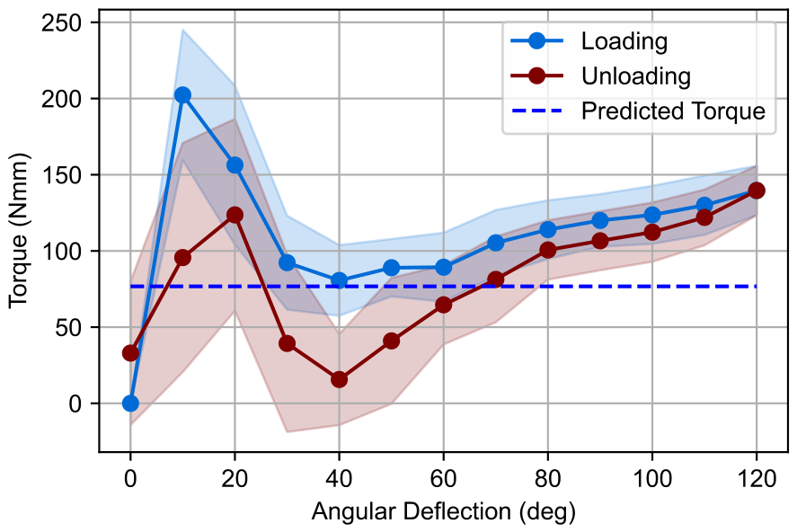
The average data from thirty torque tests loading the multi-material CORE bearing up to 120° and then unloading back to 0° in 10° increments is shown in
Figure 8. The shaded regions represent ±1 standard deviation of torque across all trials. A hysteresis loop is observed, where the unloading torque is consistently lower than the loading torque.
At around 50° of forward deflection the torque response begins to level off, with the slope decreasing substantially. For the given design parameters, the analytical model predicts a constant torque of 76.75 N·mm; however, the experimental data shows that the actual torque output varies between 50 and 150 N·mm. While the absolute torque magnitude differs from the model, the data demonstrate good consistency across trials once the initial 30° loading has been overcome. This suggests that, provided the flexures do not yield, the bearing exhibits repeatable performance with each full rotation.
The initial spike in torque is an undesirable characteristic of this assembly and stems from the notches in the sun component where the metallic strips are attached. This represents a boundary condition that is not included in the theoretical model and therefore causes significant deviation from the predicted torque output.
The observed hysteresis loop is likely due to differences in how friction acts against the rear planar side of the planets and sun, on the side contacting the work surface. Because friction acts opposite to the direction of motion, it adds to the torque of the flexures during loading and subtracts from it during unloading.
4. Finite Element Analysis
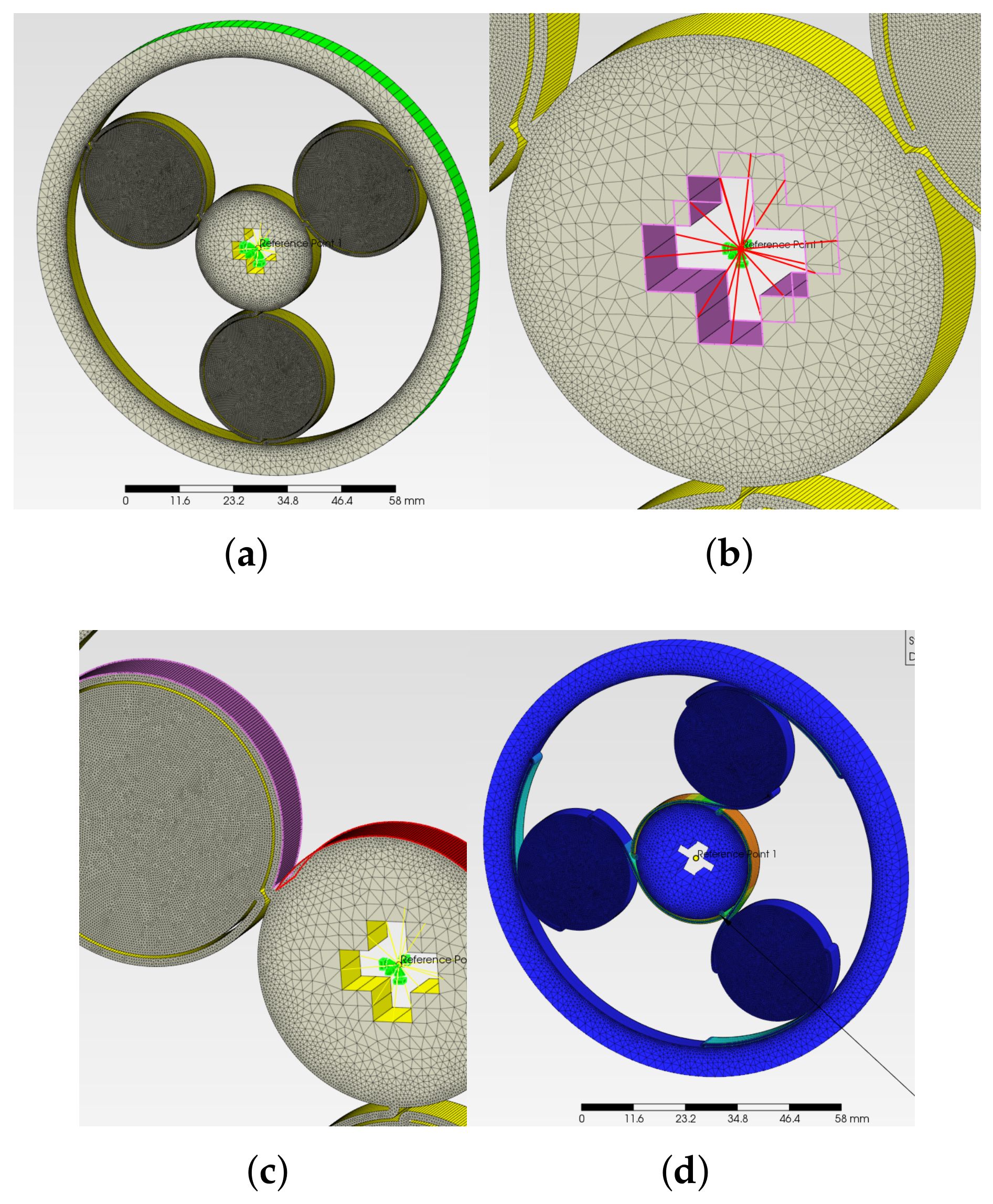
A finite element analysis (FEA) of a homogeneous CORE bearing was conducted in PrePoMax v2.1.0, an open-source Calculix-based software, to provide insight into and validation of the analytical model. This analysis used a 3D-printable monolithic geometry with a kerf width of 0.3 mm, flexure thickness of 0.8 mm, out-of-plane thickness of 5 mm, and planet/sun radii of 13.5 mm. The FEA setup consisted of the following (
Figure 9):
Mesh Conditions: A 2nd-order mesh with triangular elements was extruded through the thickness of the CORE so that each triangular element spanned the full thickness of the bearing. The mesh was refined on the flexures and contact surfaces to 0.1 mm to increase the accuracy of the model at those locations and prevent pass-through for surface contacts (
Figure 9a).
Boundary Condition: A “fixed” boundary constraint was imposed on the outer surface of the bearing ring, providing an immobile reference (
Figure 9a).
Reference Point: A reference point was defined at the center of the sun gear and given a rigid body constraint relative to the interior “+” surfaces to facilitate application of rotary displacement loads (
Figure 9b).
Surface Contacts: Surface-to-surface contact pairs were defined between each flexure contact surface and the adjacent ring, planet, or sun surface. A “hard” normal contact interaction was assigned in PrePoMax. In the underlying CalculiX functionality, this uses face-to-face penalty contact to check slave-face integration points, and contact spring elements are created when negative clearance is detected [
22]. Thus, the “hard” pressure–overclosure setting behaves as a linear penalty with default constants. It resists interpenetration during rotation but does not enforce exact impenetrability (
Figure 9c).
Displacement Condition: A specific rotary displacement was assigned to the reference point and connected surfaces, which caused the sun to rotate. This also motivated rotation of the planets about their foci and about the center of the bearing itself (
Figure 9d).
Solver: A nonlinear static CalculiX analysis was performed with geometric nonlinearity enabled. Throughout the prescribed rotation, the equilibrium of the system was iteratively updated to accommodate large deformations and changes in the contact status. PaStiX was used as the direct linear solver for the linearized systems generated for each iteration [
22].
Results: A history output, tied to the reference point, computed and retained the reaction moments raised at each displacement for later visualization. The total deflection of 120° was divided into 25 increments (
Figure 9d).
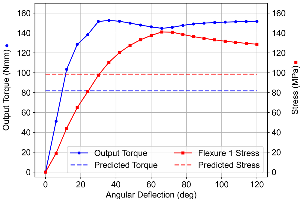
Figure 10 compares the output torque and flexure stress predicted by the FEA model with the corresponding values from the theoretical model. In contrast with the constant torque predicted by the theoretical model in Equation (
10), the FEA results exhibit transient behavior and a higher average torque and stress.
Multiple iterations of the FEA model were performed to identify if the cause of the increased average values was due to inconsistencies in the meshing parameters, surface contacts, or material properties. In each case, the FEA model consistently returned torques higher than predicted by the model or failed to converge. Variations in surface contacts proved the most difficult to test, with “hard" surface contact being the only method to yield results. However, this contact behavior is a likely source of numerical sensitivity because the CORE bearing undergoes large rotation with many interfaces that progressively close. In this penalty-based contact formulation, small changes in clearance, mesh density, or increment size change the active contact set and alter the resulting reaction moments [
22]. Therefore, the discrepancy in torque and stress magnitudes is likely due to numerical sensitivity in the multi-contact problem.
One additional explanation for the discrepancy is that the geometry at the points where the flexures merge into the planets, sun, and ring do not behave as ideal boundary conditions. As discussed with the multi-material CORE bearing, boundary conditions are not considered in the model, only uniform bending. Since the FEA model does not directly rotate through a flexure connection point, it is possible that the reactions at the connections have a farther-reaching impact than anticipated from the multi-material tests.
While the shape of the transient torque response from the FEA simulation deviates from the theoretical model of a flat line, it has good overall agreement with the shape of the multi-material experimental results. This similarity in shape suggests that the transient response is an inherent characteristic of the CORE bearing designs used in this work rather than solely a result of manufacturing or experimental error and further strengthens the theory that the boundary conditions are a non-negligible source of error.
5. Optimization
To facilitate accelerated design of CORE bearings for specific applications, we developed an optimization tool using the SciPy library in Python 3.12 for any non-monolithic bearing designs. This optimization finds the smallest bearing that meets a specified torque target while respecting material limits. The objective of the optimization is to find the minimum size of the bearing’s outer ring. The optimization is defined by a specified desired torque output, material properties (elastic modulus and yield stress), out-of-plane thickness, minimum flexure thickness (dictated by the manufacturing method), and minimum safety factor. The design variables are the geometry parameters, including sun and planet radii, flexure thicknesses, and initial radii of curvature for Type 1 and Type 2 flexures that will produce the desired torque. This optimization is solved with the SciPy SLSQP solver, an iterative gradient-based method that is well equipped to handle the nonlinear inequality constraints [
23].
The optimization uses an equality constraint that requires the output torque to match the desired torque, and two inequality constraints maintain that the flexure thicknesses and the safety factor remain above specified thresholds. By combining the objective and constraints in this manner, the smallest sun and planet radii and flexure thicknesses that will produce the desired torque without exceeding the safety factor are obtained, resulting in the smallest overall bearing geometry. As this optimization is not necessarily convex, we use a multi-start approach to converge to the most optimal ring radius.
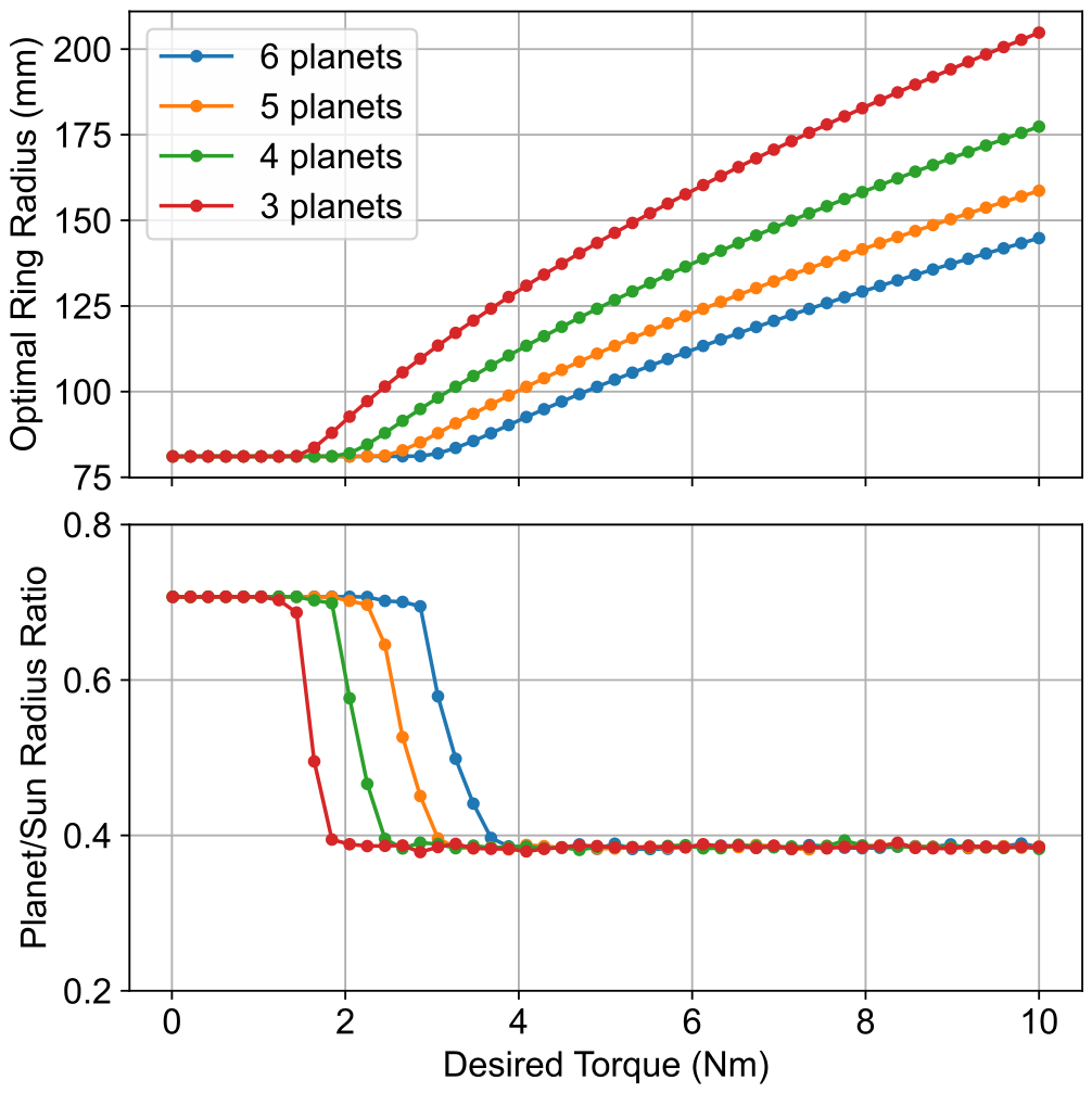
The results from the optimization are shown in
Figure 11 and demonstrate that the CORE bearing gets larger with increasing torque requirements, as expected. What is surprising is how the bearing behaves when constrained by the manufacturing tolerance, which is illustrated by the flat region in the top plot of
Figure 11. In this region, the optimization increases the torque output by decreasing the initial radius of curvature of Type 2 flexures. This is because the initial radius of curvature of Type 1 flexures, along with the radii of the sun and planets, are already at the most optimal values possible with the combination of safety factor and manufacturing tolerance. Because Type 2 flexures experience different stress conditions than Type 1 flexures when curving against the ring, the optimizer leverages their initial radius of curvature to compensate for the required torque.
When the tolerance constraint is no longer active, variations of 1–5 mm in the optimal ring diameter can occur without a multi- or warm-start approach. This indicates that the cost function landscape has multiple local minima that affect the solver’s ability to converge to the global optimum. As such, we perform multiple optimizations with variations in the starting values of the design variables to increase confidence that the optimal values have been obtained.
There is also an informative result demonstrated by the ratio of the planet and sun radii, which is visualized in
Figure 12. When the manufacturing tolerance constraint is active, the optimal ratio is near 0.7. This remains true regardless of the magnitude of the manufacturing tolerance or material properties, although the minimum possible outer ring radius does change with adjustments to either. When the manufacturing constraint on the flexure thicknesses is not active, the optimal ratio becomes 0.4. Both ratios remain the same regardless of the number of planets in the design. This indicates that any optimal bearing should follow these ratios, which can assist a designer in evaluating whether a proposed design is optimal or not.
While the ratio does not change with the number of planets, the resulting ring radius does. This matches intuition for the design as each planet can contribute additional torque to the overall device, reducing the required thickness of each flexure and, by extension, reducing the minimum radius that avoids exceeding the safety factor constraint due to bending stress.
6. Radial Stiffness Evaluation
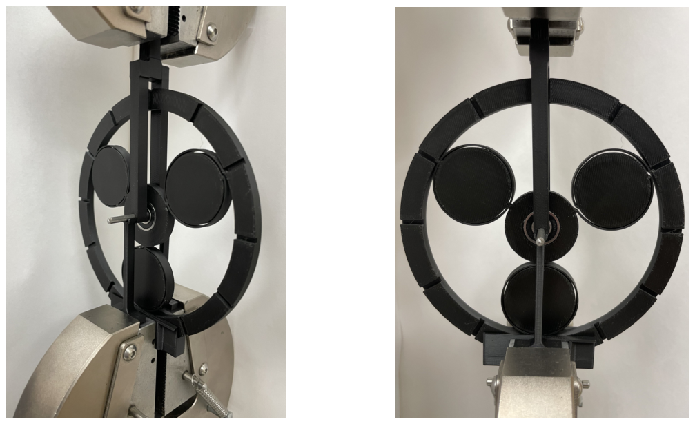
Traditional bearings are composed of a stiff load-bearing outer cylinder and a smaller internal cylinder that rotates concentrically. Precisely machined ball bearings or rods maintain a specific distance between the outer and inner cylinders, ensuring they always share the same center of rotation. In the CORE bearing, the outer ring functions as the load-bearing component while the planets keep the sun pressed into place in the center of the ring. For monolithic CORE bearing designs, a small gap is introduced between the flexures and the planets as a product of the kerf width of the selected manufacturing method. To characterize the trend between kerf width and radial stiffness, we conducted tests with three 3D-printed monolithic CORE bearings, each simulating a different manufacturing method and kerf width, as shown in
Table 2. Kerf width was the only independent variable changed between each bearing used in these tests; all the other design parameters remained the same. In each test, radial displacement up to 9 N of force was measured to evaluate the impact of kerf width on bearing radial stiffness.
An image of the radial stiffness testing setup is shown in
Figure 13. For each test, the outer ring of the bearing was gripped in the lower jaws of an Instron 3342 Tensile Tester (Instron Corporation, Newark, DE, USA). A rod passing through the center of the sun connected to a fork on both sides, which was gripped by the upper jaws of the tensile tester. The ring remained stationary while the jaws displaced the sun vertically until the force met or exceeded 8.9 N, indicating that the sun was pressing a planet into the inside of the ring. The tensile tester then returned to its original state and repeated the test. Following the second test, the outer ring was rotated 30° in the lower jaws and the test was repeated for the new orientation. This procedure was performed in 30° increments from 0° to 120°.
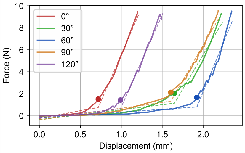
A series of test results for one CORE bearing in five orientations are shown in
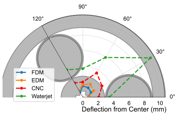
Figure 14. In each case, a change in slope is observed, corresponding to the point of maximum radial deflection prior to contact between the sun, planets, and ring. Beyond this point, the response stems from material elasticity rather than compliance in the bearing architecture. The contact point was defined at the intersection of two fitted lines via a piecewise regression and is indicated by a colored dot on each test. This method likely resulted in a slightly inflated estimate of the radial deflection but was used due to its robustness to noise and discontinuities in the data. The contact points across tests for all bearing manufacturing methods and orientations are presented in
Figure 15.
The findings of these tests indicate that a larger kerf number results in a proportionally larger radial displacement in monolithic bearings. The largest displacement occurs at the midpoint between two planets regardless of the kerf number and decreases as the loading aligns with a planet.
The three-planet bearing is nearly symmetric across the 60° orientation. As such, good agreement is expected between the 0° and 120° orientations, and between the 30° and 90° orientations.
Figure 15 shows this is largely the case for small kerf numbers. However, the bearings with the Waterjet and CNC-equivalent kerf widths exhibit noticeable deviation from this symmetry for the 30° and 90° pair. It is anticipated that the discrepancy arises from the difference in which side of the planets the Type 1 and Type 2 flexures are constructed around.
7. Discussion
The results of this research provide valuable information for determining the CORE bearing’s suitability as a torsional spring and bearing surrogate. Possible applications include exoskeletons [
24], rehabilitation devices [
25], precision hinges [
26], and prosthetic systems [
27]. The key findings include the effects of boundary conditions on the initial loading regime that deviate from the analytical model, an optimal planet/sun radius ratio to minimize planar area while satisfying torque requirements, and an inverse relationship between kerf width and radial stiffness. The following discussion interprets these findings in the context of CORE bearing design and their implications for prosthetic applications.
When the CORE bearing design was first conceived, two designs, the monolithic and split-ring bearing configurations, were put forth, each with distinct advantages and limitations [
18]. The two design configurations introduced in this paper, the split-sun and multi-material bearings, address the manufacturing challenges of the original bearing configurations. The design freedom granted by the multi-material design, which uses specific materials optimized for their function, permits more cost-effective size scalability.
The experimental behavior’s partial agreement with the predicted results indicates that users can use the analytical model to either design for a desired torque or predict torque based on given design parameters. However, as evidenced in the FEA and multi-material torque–deflection experiments, the theoretical model does not fully capture the torque–deflection behavior exhibited by the CORE bearing. The theoretical model predicts a single constant torque output over the full range of motion, whereas the experimentally observed torque output is decidedly nonlinear. The boundary conditions in practical real-world bearings provide a reasonable explanation for these deviations, but the model does not have an avenue to incorporate these discrepancies. Therefore, the current model can only be relied on for a general estimate of the output torque.
Since both the FEA and the model assert stress will be the highest in the flexures, flexure thickness and initial radius of curvature are the primary constraints when selecting CORE bearing parameters that avoid failure. While the CORE bearing was initially investigated in this work for its potential use in prostheses, the large increase in flexure stress that occurs when curvature radii are small limits the CORE bearing’s capacity for miniaturization when a specific torque is required.
Additionally, the relationship between kerf width and radial stiffness indicates that the manufacturing method and bearing design have a significant influence on the CORE bearing’s ability to replace traditional bearings for applications where only a limited range of motion is needed. In contrast, the axial stiffness (response to pushing the sun in and out of the plane of the ring) is extremely low regardless of the manufacturing medium. The flexures can be easily stretched beyond their elastic limit when the bearing components come out of plane. As such, hard end stops are recommended to prevent large motions in that direction.
Up to this point, all CORE bearing configurations have had a uniform circular profile. An emerging type of bearing explores non-circular profiles for the sun and planets as an additional way of inducing a deliberately variable or nonlinear torque profile on the output. This style of design has also been explored in forms different than a bearing by Shaw et al. in their paper on shape-morphing CRAMs as a method of producing alternate morphing profiles [
19] and by Decker et al. as they customize the kinematics of rolling-contact joints using non-circular geometries [
28]. The challenge of this approach as applied to a CORE bearing is ensuring consistent radial contact throughout the range of motion of the device, a constraint that was not present for Shaw et al. because their assembly tensioned each CRAM element against its neighbors. Another challenge presented by non-circular CORE bearings is minimizing stress concentrations in the flexures while still permitting rotational motion.
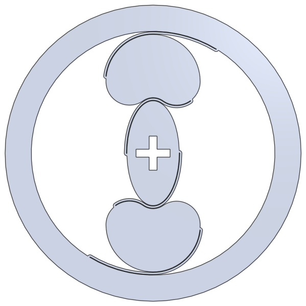
The concept shown in
Figure 16 implements an ellipse-shaped sun with inverse-shaped planets. This enables axial rotation of the sun about the center point of the bearing while maintaining full diametric contact on the long axis of the ellipse.
The need for non-circular bearing geometry is motivated by the exploration of nonlinear torque profiles. Each flexible member of the bearing can be treated as a beam, where the curvature of that beam is determined by the profile of the sun, planet, or ring it resides next to. Because the moment, and therefore the stress, experienced at any point in the beam is proportional to the curvature, there is a relationship between the curvature of the flexible members and the torque required to deflect the mechanism. Introducing non-circular geometry in the design is expected to create new possibilities for nonlinear torque profiles. Such profiles on circular geometry have been explored previously by Halverson et al. through the implementation of non-constant flexure curvature [
21].
8. Conclusions
The CORE bearing mechanism presents advantages in sustaining radial loads due to the circular outer ring and generates a restorative torque for a large range of motion due to the compliance of curved flexures. These advantages motivated investigation into improving CORE bearing design and performance and its suitability as a torsional spring and bearing surrogate in PEA systems. Alternative designs were proposed, and understanding of the CORE bearing’s capabilities was advanced.
The two additional designs proposed in this work, the split-sun and multi-material CORE bearings, capitalize on the strengths of the original CORE bearing configurations. The mathematical model proposed by Cannon et al. is useful for estimating the general range of output torque for a CORE bearing, but the experimental and FEA results demonstrate that the assumption of constant torque in the model is not consistent with current designs due to unmodeled effects of boundary conditions. It was also hypothesized, and then confirmed, that radial stiffness scales inversely with the fabrication method kerf width; reduced kerf width increases radial stiffness.
This work furthers understanding of the CORE bearing, which, due to its large range of motion, restorative torque, and high radial stiffness, can function as a torsional spring and bearing surrogate.
Author Contributions
Software, S.S.; validation, A.R. and S.S.; investigation, A.R., S.S. and E.F.; writing—original draft preparation, A.R. and S.S.; writing—review and editing, A.R., S.S., E.F., A.C., N.U. and L.L.H.; visualization, A.R., S.S., E.F. and A.C.; supervision, N.U. and L.L.H.; funding acquisition, L.L.H. All authors have read and agreed to the published version of the manuscript.
Funding
This work is funded by the National Science Foundation under Award No. 2344766, “Collaborative Research: Integrating Optimal Function and Compliant Mechanisms for Ubiquitous Lower-Limb Powered Prostheses,” a collaborative project with the University of Notre Dame.
Data Availability Statement
Data are available on request from the corresponding author.
Acknowledgments
We express thanks for the technical input on prosthetic requirements from Edgar Bolívar-Nieto and Minho Lee of the University of Notre Dame. We acknowledge Mihai Stanciu and Annie O’Byran of Brigham Young University for their assistance in fabricating and testing the multi-material CORE bearing.
Conflicts of Interest
The authors declare no conflicts of interest.
Abbreviations
The following abbreviations are used in this manuscript:
| CORE | Compliant Rolling-Contact Element |
| PEA | Parallel Elastic Actuator |
| SEA | Series Elastic Actuator |
| FEA | Finite Element Analysis |
| CRAM | Compliant Rolling-Contact Architected Materials |
| FDM | Fused Deposition Modeling |
| CNC | Computer Numerical Control |
| EDM | Electrical Discharge Machining |
| SLA | Stereo-Lithography Apparatus |
| SLSQP | Sequential Least Squares Programming |
References
- Cannon, J.R. Compliant Mechanisms to Perform Bearing and Spring Function in High Precision Applications. Master’s Thesis, Brigham Young University, Provo, UT, USA, 2004. Available online: https://scholarsarchive.byu.edu/etd/229 (accessed on 16 December 2025).
- Maat, B.; Smit, G.; Plettenburg, D.; Breedveld, P. Passive prosthetic hands and tools: A literature review. Prosthet. Orthot. Int. 2018, 42, 66–74. [Google Scholar] [CrossRef] [Scilit] [PubMed]
- Engdahl, S.M.; Christie, B.P.; Kelly, B.; Davis, A.; Chestek, C.A.; Gates, D.H. Surveying the interest of individuals with upper limb loss in novel prosthetic control techniques. J. Neuroeng. Rehabil. 2015, 12, 53. [Google Scholar] [CrossRef] [Scilit]
- Olsen, C.D.; Olsen, N.R.; Stone, E.S.; Tully, T.N.; Paskett, M.D.; Teramoto, M.; Clark, G.A.; George, J.A. Electromyographically controlled prosthetic wrist improves dexterity and reduces compensatory movements without added cognitive load. Sci. Rep. 2024, 14, 23248. [Google Scholar] [CrossRef] [Scilit]
- Batista, P.G.; Vieira, A.C.; Gaspar, P.D. Robotic Prostheses and Neuromuscular Interfaces: A Review of Design and Technological Trends. Machines 2025, 13, 804. [Google Scholar] [CrossRef] [Scilit]
- Dupont, P.E.; Nelson, B.J.; Goldfarb, M.; Hannaford, B.; Menciassi, A.; O’Malley, M.K.; Simaan, N.; Valdastri, P.; Yang, G.Z. A decade retrospective of medical robotics research from 2010 to 2020. Sci. Robot. 2021, 6, eabi8017. [Google Scholar] [CrossRef] [Scilit]
- Asif, M.; Tiwana, M.I.; Khan, U.S.; Qureshi, W.S.; Iqbal, J.; Rashid, N.; Naseer, N. Advancements, trends and future prospects of lower limb prosthesis. IEEE Access 2021, 9, 85956–85977. [Google Scholar] [CrossRef] [Scilit]
- Pratt, G.A.; Williamson, M.M. Series elastic actuators. In Proceedings of the 1995 IEEE/RSJ International Conference on Intelligent Robots and Systems. Human Robot Interaction and Cooperative Robots, Pittsburgh, PA, USA, 5–9 August 1995; IEEE: New York, NY, USA, 1995; Volume 1, pp. 399–406. [Google Scholar] [CrossRef] [Scilit]
- Jin, H.; Moon, C.; Kim, T.; Seo, T. Belt Sanding Robot for Large Convex Surfaces Featuring SEA Arms and an Active Re-Tensioner with PI Force Control. Machines 2025, 13, 1012. [Google Scholar] [CrossRef] [Scilit]
- Bolívar Nieto, E.A.; Rezazadeh, S.; Gregg, R.D. Minimizing Energy Consumption and Peak Power of Series Elastic Actuators: A Convex Optimization Framework for Elastic Element Design. IEEE/ASME Trans. Mechatron. 2019, 24, 1334–1345. [Google Scholar] [CrossRef] [Scilit] [PubMed]
- Yang, K.; Dickens, M.; Schmiedeler, J.; Bolívar-Nieto, E. Extending the Benefits of Parallel Elasticity Across Multiple Actuation Tasks: A Geometric and Optimization-Based Approach. IEEE/ASME Trans. Mechatron. 2025, 30, 7855–7865. [Google Scholar] [CrossRef] [Scilit]
- Collins, S.H.; Wiggin, M.B.; Sawicki, G.S. Reducing the energy cost of human walking using an unpowered exoskeleton. Nature 2015, 522, 212–215. [Google Scholar] [CrossRef] [Scilit] [PubMed]
- Van Der Spaa, L.F.; Wolfslag, W.J.; Wisse, M. Unparameterized Optimization of the Spring Characteristic of Parallel Elastic Actuators. IEEE Robot. Autom. Lett. 2019, 4, 854–861. [Google Scholar] [CrossRef] [Scilit]
- Guo, S.; Gregg, R.D.; Bolívar-Nieto, E. Convex Optimization for Spring Design of Parallel Elastic Actuators. In Proceedings of the 2022 American Control Conference (ACC), Atlanta, GA, USA, 8–10 June 2022; IEEE: New York, NY, USA, 2022; pp. 3688–3694. [Google Scholar] [CrossRef] [Scilit]
- Ford, J.P. Rolamite Fundamentals; Technical Report; Sandia Laboratories: Albequerque, NM, USA, 1969. [Google Scholar]
- Hillberry, B.M.; Hall, A.S., Jr. Rolling Contact Joint. U.S. Patent 3,932,045, 6 January 1976. [Google Scholar]
- Jeanneau, A.; Herder, J.; Laliberte, T.; Gosselin, C. A Compliant Rolling Contact Joint and Its Application in a 3-DOF Planar Parallel Mechanism With Kinematic Analysis. In Proceedings of the International Design Engineering Technical Conferences and Computers and Information in Engineering Conference, Salt Lake City, UT, USA, 28 September–2 October 2004; ASME: New York, NY, USA, 2004; pp. 689–698. [Google Scholar] [CrossRef] [Scilit]
- Cannon, J.R.; Lusk, C.P.; Howell, L.L. Compliant Rolling-Contact Element Mechanisms. In Proceedings of the International Design Engineering Technical Conferences and Computers and Information in Engineering Conference, Brooklyn, NY, USA, 3–6 August 2008; ASME: New York, NY, USA, 2008; pp. 3–13. [Google Scholar] [CrossRef] [Scilit]
- Shaw, L.A.; Chizari, S.; Dotson, M.; Song, Y.; Hopkins, J.B. Compliant rolling-contact architected materials for shape reconfigurability. Nat. Commun. 2018, 9, 4594. [Google Scholar] [CrossRef] [Scilit] [PubMed]
- Halverson, P.A.; Howell, L.L.; Bowden, A.E. A Flexure-Based Bi-Axial Contact-Aided Compliant Mechanism for Spinal Arthroplasty. In Proceedings of the 32nd Mechanisms and Robotics Conference, Parts A and B, International Design Engineering Technical Conferences and Computers and Information in Engineering Conference, Brooklyn, NY, USA, 3–6 August 2008; ASME: New York, NY, USA, 2008; Volume 2, pp. 405–416. [Google Scholar] [CrossRef] [Scilit]
- Halverson, P.A.; Howell, L.L.; Magleby, S.P. Tension-based multi-stable compliant rolling-contact elements. Mech. Mach. Theory 2010, 45, 147–156. [Google Scholar] [CrossRef] [Scilit]
- Dhondt, G. CalculiX CrunchiX User’s Manual. Version 2.23. 2025. Available online: https://www.dhondt.de/ (accessed on 15 May 2026).
- Virtanen, P.; Gommers, R.; Oliphant, T.E.; Haberland, M.; Reddy, T.; Cournapeau, D.; Burovski, E.; Peterson, P.; Weckesser, W.; Bright, J.; et al. SciPy 1.0: Fundamental Algorithms for Scientific Computing in Python. Nat. Methods 2020, 17, 261–272. [Google Scholar] [CrossRef] [Scilit] [PubMed]
- Al-Dahiree, O.S.; Ghazilla, R.A.R.; Tokhi, M.O.; Yap, H.J.; Albaadani, E.A. Design of a compact energy storage with rotary series elastic actuator for lumbar support exoskeleton. Machines 2022, 10, 584. [Google Scholar] [CrossRef] [Scilit]
- Bumbard, K.B.; Herrington, H.; Goh, C.H.; Ibrahim, A. Incorporation of torsion springs in a knee exoskeleton for stance phase correction of crouch gait. Appl. Sci. 2022, 12, 7034. [Google Scholar] [CrossRef] [Scilit]
- Yang, M.; Jia, T.; Yang, Y.; Liu, S.; Zhou, T. Design and Characteristic Analysis of a Novel Compact Torsion Spring for Assistive Exoskeleton Robots. IEEE Access 2025, 13, 115151–115159. [Google Scholar] [CrossRef] [Scilit]
- Ghaffar, A.; Dehghani-Sanij, A.A.; Xie, S.Q. Actuation system modelling and design optimization for an assistive exoskeleton for disabled and elderly with series and parallel elasticity. Technol. Health Care 2023, 31, 1129–1151. [Google Scholar] [CrossRef] [Scilit] [PubMed]
- Decker, C.J.; Chen, T.G.; Yuen, M.C.; Wood, R.J. Noncircular rolling contact joints enable programmed behavior in robotic linkages. Proc. Natl. Acad. Sci. USA 2026, 123, e2521406123. [Google Scholar] [CrossRef] [Scilit] [PubMed]
Figure 1.
A 3D-printed CORE bearing with the ring, sun, planets, and flexures labeled.
Figure 1.
A 3D-printed CORE bearing with the ring, sun, planets, and flexures labeled.
Figure 2.
A rolling-contact joint made with 3D-printed rolling elements and spring steel flexures.
Figure 2.
A rolling-contact joint made with 3D-printed rolling elements and spring steel flexures.
Figure 3.
Rotational motion of the CORE bearing. The outer ring is fixed and a lever is used to turn the sun. Tick marks on the ring are spaced 20° apart. The curved flexures initially wrap around the planets and are highlighted in white. The red arrows indicate the direction of element motion.
Figure 3.
Rotational motion of the CORE bearing. The outer ring is fixed and a lever is used to turn the sun. Tick marks on the ring are spaced 20° apart. The curved flexures initially wrap around the planets and are highlighted in white. The red arrows indicate the direction of element motion.
Figure 4.
A labeled diagram of the geometric parameters that influence the CORE bearing’s stress and torque output.
Figure 4.
A labeled diagram of the geometric parameters that influence the CORE bearing’s stress and torque output.
Figure 5.
The three homogeneous CORE bearing designs: (a) monolithic; (b) split-ring; (c) split-sun.
Figure 5.
The three homogeneous CORE bearing designs: (a) monolithic; (b) split-ring; (c) split-sun.
Figure 6.
Multi-material CORE bearing with spring steel flexures. The ring, planets, sun, and bottom cover are 3D-printed. The bearing is 140 mm in diameter and 15 mm tall.
Figure 6.
Multi-material CORE bearing with spring steel flexures. The ring, planets, sun, and bottom cover are 3D-printed. The bearing is 140 mm in diameter and 15 mm tall.
Figure 7.
Multi-material torque testing setup. The outer ring is fixed with a C-clamp, and the sun is rotated counterclockwise using a wrench connected to a torque measurement device.
Figure 7.
Multi-material torque testing setup. The outer ring is fixed with a C-clamp, and the sun is rotated counterclockwise using a wrench connected to a torque measurement device.
Figure 8.
Torque–deflection data from the multi-material CORE bearing torque testing. The bearing is loaded CCW to 120° and unloaded CW in 10° increments for 30 trials. The shaded regions represent ±1 standard deviation. Blue = loading, red = unloading; dashed line = analytical model prediction.
Figure 8.
Torque–deflection data from the multi-material CORE bearing torque testing. The bearing is loaded CCW to 120° and unloaded CW in 10° increments for 30 trials. The shaded regions represent ±1 standard deviation. Blue = loading, red = unloading; dashed line = analytical model prediction.
Figure 9.
Overview of the FEA process for the 3-planet monolithic CORE bearing. (a) Mesh setup and boundary condition (green). (b) Rigid body constraint (purple). (c) One contact pair (red and purple). (d) Simulation results.
Figure 9.
Overview of the FEA process for the 3-planet monolithic CORE bearing. (a) Mesh setup and boundary condition (green). (b) Rigid body constraint (purple). (c) One contact pair (red and purple). (d) Simulation results.
Figure 10.
Comparison of output torque (blue) and flexure stress (red) predicted by the FEA (solid) and theoretical model (dashed).
Figure 10.
Comparison of output torque (blue) and flexure stress (red) predicted by the FEA (solid) and theoretical model (dashed).
Figure 11.
Effect of the design torque and number of planets on the minimum ring radius and relative sizes of the sun and planets. The inputs for this sequence of optimizations were: . The initial flat region in the top plot represents where the flexure thickness is constrained by and output torque is modulated by changing only.
Figure 11.
Effect of the design torque and number of planets on the minimum ring radius and relative sizes of the sun and planets. The inputs for this sequence of optimizations were: . The initial flat region in the top plot represents where the flexure thickness is constrained by and output torque is modulated by changing only.
Figure 12.
Optimization results showing the emergent planet-to-sun radius ratios when (a) ratio ≈ 0.7 and the manufacturing constraint is not active, and (b) ratio ≈ 0.4 when flexure thickness is constrained by the manufacturing method.
Figure 12.
Optimization results showing the emergent planet-to-sun radius ratios when (a) ratio ≈ 0.7 and the manufacturing constraint is not active, and (b) ratio ≈ 0.4 when flexure thickness is constrained by the manufacturing method.
Figure 13.
Radial stiffness experimental setup. The lower jaw held the bearing stationary while the upper jaw pulled the sun upward until the force exceeded 2 lbs.
Figure 13.
Radial stiffness experimental setup. The lower jaw held the bearing stationary while the upper jaw pulled the sun upward until the force exceeded 2 lbs.
Figure 14.
Radial force/deflection data for the CORE bearing with the wire EDM kerf size (0.41 mm). Dotted lines indicate the piecewise linear fit applied to the data to determine the approximate location of the change in stiffness, marked with a dot on each trial, that indicates contact between the sun, planet, and ring.
Figure 14.
Radial force/deflection data for the CORE bearing with the wire EDM kerf size (0.41 mm). Dotted lines indicate the piecewise linear fit applied to the data to determine the approximate location of the change in stiffness, marked with a dot on each trial, that indicates contact between the sun, planet, and ring.
Figure 15.
Visualization of the radial displacement from center for each manufacturing method at each 30° increment. Radial displacements are not to scale.
Figure 15.
Visualization of the radial displacement from center for each manufacturing method at each 30° increment. Radial displacements are not to scale.
Figure 16.
Non-circular geometry implemented in a CORE bearing structure.
Figure 16.
Non-circular geometry implemented in a CORE bearing structure.
Table 1.
Design parameters for the multi-material CORE bearing used for torque testing.
Table 1.
Design parameters for the multi-material CORE bearing used for torque testing.
| Parameter | Value (mm) |
|---|
| 20 |
| 16.9, 15.4 |
| 0.1524 |
| b | 15 |
| E | 210 GPa |
| 3 |
Table 2.
Kerf sizes associated with each fabrication method.
Table 2.
Kerf sizes associated with each fabrication method.
| Type | Kerf # (mm) |
|---|
| FDM | 0.20 |
| Wire EDM | 0.41 |
| CNC | 0.80 |
| Waterjet | 1.58 |
| Disclaimer/Publisher’s Note: The statements, opinions and data contained in all publications are solely those of the individual author(s) and contributor(s) and not of MDPI and/or the editor(s). MDPI and/or the editor(s) disclaim responsibility for any injury to people or property resulting from any ideas, methods, instructions or products referred to in the content. |




 ,
,