1. Introduction
In robotics research, over the years, various control approaches have been developed to guide a mobile robot along a smooth and obstacle-free path. Several successful approaches in this area have been demonstrated in many experiments using different sensors and methodologies [
1]. The overall purpose of this control problem is to guide the robot from its initial position to a desired position [
2]. Mobile robot (MR) path tracking has been a subject of interest among researchers due to its potential application in developing an efficient navigation system for robots [
3,
4].
The field of fuzzy logic is well recognized for its use in solving control problems that require heuristic knowledge. Fuzzy control requires linguistic rules and expert knowledge, expressed as membership functions and fuzzy rules. The input–output relationship of the membership functions is specified, mostly on an if-then basis. Despite its simple architecture, it can solve complex control problems. In robotics, fuzzy logic is used to control systems that account for uncertainties and imprecision [
5]. Fuzzy controllers have been developed as an alternative to conventional control, enabling efficient control of nonlinear, uncertain, and complex systems [
6]. Also, developed from the conventional fuzzy methodology, type-2 fuzzy is more effective at addressing system uncertainties by allowing uncertainty in the definition of membership functions. In the field of mobile robotics, type-1 and type-2 fuzzy controllers have been continuously developed and applied to solve real robotic problems. In type-2 methodology, applications include collision avoidance, trajectory tracking, balancing control, and controller design. Recent studies, such as [
7], have also demonstrated the effectiveness of fuzzy logic controllers in mobile robot navigation and obstacle avoidance. A significant component of a mobile robot for real-world operation is a path-tracking system that can improve performance [
8,
9].
Path tracking is the robot’s ability to follow the intended path from one location to any point in a plane. Path tracking has been discussed in various research studies. This paper presents a comparative study of type-1 and type-2 fuzzy controllers for differential-drive trajectory tracking, aiming to improve robot path tracking performance. To validate performance, both controllers are tested on various trajectories, with particular attention to the advantages of type-2 fuzzy controllers in handling uncertainties and improving tracking accuracy, thereby providing a more robust solution to the path-tracking challenge in mobile robotics.
Although numerous control strategies have recently been proposed for mobile robot trajectory tracking, including sliding-mode control, model predictive control, and hybrid intelligent controllers, fuzzy logic controllers remain widely used due to their ability to handle nonlinearities and uncertainties. However, relatively few studies provide controlled benchmarking comparisons between type-1 and type-2 fuzzy controllers under identical dynamic conditions. The present work aims to provide such a systematic comparison using a nonlinear dynamic model and a set of trajectories of increasing complexity.
This paper provides a rigorous, fair comparison of type-1 and type-2 fuzzy controllers for trajectory tracking of a differential drive robot under identical conditions. Unlike several previous studies that reported limited or scenario-dependent differences between type-1 and type-2 fuzzy controllers, the present study performs a controlled comparison under identical operating conditions using a nonlinear dynamic model and reference trajectories of increasing geometric complexity. The contribution of this work lies in conducting a systematic comparison based on a nonlinear dynamic model with torque inputs, developing refined type-1 and interval type-2 fuzzy architectures, and performing extensive evaluations on challenging reference trajectories. A comprehensive quantitative benchmarking is provided using RMSE, angular error, and response time, together with a discussion in relation to the recent literature. This study emphasizes that the contribution lies in establishing a controlled, reproducible benchmarking framework rather than proposing a new fuzzy control structure. The main contributions of this paper can be summarized as follows:
Development of a fair and reproducible benchmarking framework for comparing type-1 and type-2 fuzzy logic controllers.
Implementation of both controllers under strictly identical nonlinear dynamic conditions, including the same robot model, inputs, initial conditions, and reference trajectories.
Design of structurally equivalent fuzzy controllers with identical membership functions, rule bases, and scaling factors.
Evaluation across multiple trajectory tracking scenarios of increasing complexity.
Quantitative comparison using distance error, angular error, and response time.
Demonstration that performance improvements are primarily linked to uncertainty modeling via the footprint of uncertainty (FOU), rather than tuning or structural differences.
The paper is organized as follows:
Section 2 discusses related work, emerging trends, drawbacks of fuzzy logic, other control systems, and advances implemented in mobile robots.
Section 3 provides the system design of differential-drive mobile robots and the detailed mathematical modeling of the mobile robot. The development of FLC (T1FL and T2FL) for a mobile robot is presented in
Section 4. The proposed controllers for a mobile robot and the developed FLC are given in
Section 5. Comparative studies of both types of FLCs for a mobile robot are conducted using different trajectories. Finally, conclusions are given in
Section 6.
2. Related Work
Autonomous systems, particularly autonomous mobile robots, are receiving significant attention from research and industry communities. To operate effectively in the physical world, any autonomous robot must find the required path and navigate from its initial position to the goal location. Navigation is the process by which a robot executes a planned course of action for traveling between different places in its environment using its reasoning facility. Path planning is a subset of navigation that involves creating a planned course of action from the given environment. The primary goal of path planning is to create a path from a robot’s initial position to its goal position that avoids collisions or encumbrances from moving objects, such as other robots, obstacles, or people or agents. Paper [
10] presents an overview of autonomous mobile robots (AMRs) in intra-logistics, focusing on technological advancements, decision-making strategies, and their diverse applications in manufacturing, ware housing, and healthcare. AMRs and the challenges of navigation strategies adopted towards localization are presented in [
11]. It outlines that localization is an essential ability for such robots to estimate their position in both static and dynamic environments. In static environments, the process is simpler, but in dynamic environments, it becomes more complicated because there are moving objects besides the robot. In Ref. [
12], new algorithms are proposed for autonomous mobile robots to improve efficiency and safety in a warehouse. The use of agent-based modeling enables the authors to investigate deadlock- and collision-avoidance approaches that further develop supply chains. The integration of fuzzy logic into controllers significantly enhances path tracking for mobile robots and has achieved notable applications in robotics. Path tracking is one of the most significant navigation strategies in mobile robotics. Researchers have proposed various methodological approaches to enhance path tracking for mobile robots in both outdoor and indoor environments. In Ref. [
13], a comprehensive discussion of challenges and future perspectives in the field is presented. The main topics discussed are Kalman filters, SLAM, and various computing platforms supporting mobile robotics. The authors of this work discuss advances and applications of mobile robots, particularly in indoor and outdoor environments. A detailed review of key technologies in path planning for mobile robots is presented in the paper [
14], including environmental modeling, 2-D grid mapping, and 3-D point cloud generation. This will be done by discussing different aspects and by pointing out the use of both classical and heuristic path-planning algorithms to find the best route while accounting for obstacles. It can be argued that any efficient path-tracking strategy will be useful for an intelligent mobile robot, enabling better trajectory planning, obstacle avoidance, and motion in unstructured, complex environments. In Ref. [
15], various path-planning techniques are reviewed, including the Dynamic Window Approach and its integration with fuzzy logic, which enhance a mobile robot’s ability to avoid dynamic obstacles in unstructured, complex environments through real-time adaptation and multi-sensor data fusion. The review paper [
16] has identified that only an efficient path-planning algorithm, essentially Reactive Computing, can enable intelligent mobile robots to cope with dynamic obstacles while navigating through complex scenarios. Advanced techniques, such as neural networks, further embed their capability to optimize paths and navigate safely.
The literature on fuzzy logic control for mobile robots has evolved significantly, highlighting various methodologies to enhance path-tracking performance. In paper [
17], a comprehensive fuzzy-logic-based control system is designed specifically for autonomous mobile robot navigation in indoor environments. Their work emphasized integrating fuzzy logic into local and global navigation, path planning, and obstacle avoidance, demonstrating its effectiveness through simulations that evaluated various trajectories. The results highlighted the potential of fuzzy logic in improving navigation algorithms, establishing a foundational understanding of its role in mobile robotics. In addition, recent studies have also demonstrated the applicability of fuzzy logic controllers in real-time navigation and obstacle avoidance. For example, Ref. [
18] proposed a fuzzy logic controller for autonomous mobile robots in dynamic environments, showing effective performance in both simulation and experimental scenarios. Building on this foundation, Ref. [
19] advanced the field further by introducing a type-2 fuzzy hybrid controller network (T2FHC) specifically for robotic systems. Their research presented a novel fuzzy neural network that combined elements of type-2 fuzzy CMAC (Cerebellar Model Articulation Controller) and BELC (Backpropagation Error Learning Controller), leading to significant improvements in mobile robot position tracking. The comparative analysis revealed that T2FHC outperformed traditional controllers, achieving lower accumulated RMSE values across multiple experiments. This study not only underscored the enhanced precision and stability offered by type-2 fuzzy control but also marked a shift towards more complex and capable fuzzy architectures in the context of robotic motion control [
19].
Most recently, Ref. [
20] explored integrating fuzzy logic with kinematic models to refine mobile robot motion control. Their approach addressed the limitations of conventional kinematic and dynamic control methods, particularly the inability to adapt to environmental changes or ensure smooth trajectory transitions. By incorporating fuzzy logic into the motion controller, the robot’s ability to follow predefined paths with improved quality is enhanced, particularly when faced with parameter uncertainties. The simulation results reinforced the notion that fuzzy logic, when combined with traditional control methods such as PID, can significantly improve the performance of mobile robots in dynamic settings [
20].
As is known, the range of applications of fuzzy logic is extremely broad. This motivated further development of both the classical type of fuzzy sets and type-n fuzzy sets. To date, numerous research papers have been published on the use of type-2 fuzzy sets for robot control problems in various aspects. The aims of using type-2 fuzzy sets in these papers may be to increase the robustness of the control system to known or unknown uncertainties and to enhance the functionality or knowledge. The application of type-n (especially type-2) fuzzy logic in robotics and control systems to represent uncertainty is supported by a growing body of recent research [
9,
21,
22].
In the literature, some researchers have attempted to solve the path-tracking problem for mobile robots using fuzzy control methods. The design of a type-1 fuzzy controller (T1FC) for path tracking of the mobile robot has been presented. They investigated the effects of performance changes driven by control factors such as speed, acceleration, and launch conditions. It has been shown that optical flow was used in a control scheme based on a simple PID controller, but that T1FC was used to control the forward translation and the angle of rotation. The traditional Mamdani fuzzy model has been used in implemented scenarios [
23,
24]. Two types of T1 control techniques, neuro-fuzzy and parallel with state feedback control, have been combined to enable the mobile robot to track a reference path. This approach enables mobile robots to operate as smoothly as possible despite control delays and nonlinear interactions, while maintaining asymptotic trajectory tracking. The T1 fuzzy technique has been applied relatively recently to control the robot’s heading by identifying the control gains, demonstrating that this control model can handle parameter changes.
The membership functions of the universal fuzzy processor were defined based on the objective function in [
11,
25]. Both normal fuzzy controllers and type-1 fuzzy controllers have been considered for path tracking in previous works. A standard fuzzy controller has been applied to the tracking control of a two-wheeled robot with nonholonomic constraints, handling them effectively to achieve good performance.
Similarly, type-1 fuzzy systems have been widely used to address trajectory tracking problems. For example, Tolossa et al. [
26] developed an optimized fuzzy logic controller for trajectory tracking of a two-wheeled differential-drive mobile robot, while Akmal et al. [
27] investigated interval type-2 fuzzy logic control for mobile robot trajectory tracking under measurement noise. In addition, fuzzy control approaches have also been successfully applied to real-time mobile robot systems, demonstrating their effectiveness in handling nonlinear dynamics and improving control performance [
28]. However, many existing approaches either rely mainly on type-1 fuzzy systems or focus on specific optimized fuzzy structures rather than providing a controlled comparison between type-1 and type-2 fuzzy controllers under identical nonlinear dynamic conditions.
In recent years, several researchers have suggested using interval type-2 fuzzy systems for mobile robot path-tracking applications [
17,
20,
21,
27]. In papers [
22,
26], a center-of-gravity (COG)-based aggregate and a centroid-of-centroids type-2 fuzzy system are designed to address the path-tracking problem and compensate for non-synchronized actuation in unmanned ground vehicles (UGVs). A new concept of a type-2 fuzzy system, called the bipolar dual, is introduced [
8,
29]. Here, a new approach for the type reduction in an interval type-2 fuzzy system is proposed [
30,
31]. Then, applications in path tracking for non-holonomic 2-DOF robotic vehicles and speed control of a BLDC electric motor are studied with the bipolar dual [
32,
33]. The simulation and experimental results demonstrate the effectiveness of the presented bipolar dual event-based type-2 fuzzy control.
Even with the encouragement of robustness and adaptability of the new and well-known mathematical apparatus, no systematic comparison is given since the aim is primarily to demonstrate the superior control performance of type-2 over type-1 fuzzy logic-based control systems when certain limitations need to be overcome. Given these facts, a systematic comparison of the advantages and, possibly, the disadvantages of applying type-1 and type-2 fuzzy logic to robot motion control can be particularly beneficial to the robotics field. The objectives of this paper are as follows: determination of the degree of robustness of type-1 and type-2 fuzzy logic-based path tracking controllers concerning known and unknown perturbations in the motion control problem of a mobile robot [
30,
31,
32,
33]. This progression in research highlights critical advancements in fuzzy control systems, transitioning from traditional fuzzy-logic applications to more sophisticated type-2 fuzzy methodologies, ultimately improving path-tracking and navigation capabilities for mobile robots.
In Ref. [
34], the application of Takagi–Sugeno FLC, artificial neural networks, and neuro-fuzzy controllers was investigated for the path-following behavior of a tricycle mobile robot. Other recent studies have also addressed this problem. For instance, Ref. [
35] proposed a fuzzy steering controller based on a symmetric distribution of triangular membership functions for a nonholonomic mobile robot, improving tracking accuracy and disturbance rejection in simulation. In addition, Ref. [
36] proposed a fuzzy adaptive model predictive control approach for trajectory tracking of differential tracked robots, where fuzzy logic is used to adjust control parameters online, leading to improved tracking accuracy, faster convergence, and enhanced stability in dynamic environments. Furthermore, Ref. [
37] proposed an exponential trajectory tracking controller based on Lyapunov stability theory, providing formal stability guarantees and fast convergence. More recently, Ref. [
38] proposed a dynamic model predictive control (DMPC) strategy for trajectory tracking of mobile robots, demonstrating significant improvements in tracking accuracy and computational efficiency compared to conventional MPC methods.
Recent studies have highlighted that trajectory tracking of wheeled mobile robots remains challenging due to strong nonlinearities and coupling effects, which have motivated the development of advanced nonlinear and hybrid control strategies. For example, Huang and Gao [
39] proposed a backstepping-based sliding-mode controller that achieves accurate tracking under modeling uncertainties and external disturbances. These recent trends provide a broader state-of-the-art context for the present comparative investigation of type-1 and type-2 fuzzy logic controllers. More recently, hybrid schemes combining fuzzy logic with model predictive control have been proposed to further enhance robustness in the presence of large tracking errors and dynamic environments. In particular, Zhang et al. [
36] introduced a fuzzy adaptive virtual-steering-coefficient MPC framework for differential tracked robots, demonstrating faster convergence, reduced tracking errors, and improved stability compared to classical MPC approaches.
In our previous work [
40], we introduced a basic type-1 fuzzy controller with three membership functions and nine rules, which performed well for simple trajectories but struggled with more complex paths due to its limited handling of uncertainties. However, in the present paper, we extend that work by developing a more advanced fuzzy controller architecture that incorporates a refined type-1 design with five membership functions and twenty-five rules, and by introducing a type-2 fuzzy logic controller to effectively manage uncertainties, resulting in faster response times, improved accuracy, and enhanced robustness, further supported by integrating dynamic modeling and testing on additional complex trajectories scenarios.
This paper compares type-1 and type-2 fuzzy controllers for path tracking of a mobile robot. It demonstrates that a type-2 fuzzy logic controller provides better results than a type-1 fuzzy logic controller. The mobile robot has two front steering wheels and two rear driving wheels with velocity control to execute the planned path. The simulation analysis of the mentioned controllers is conducted across several scenarios. The two cases considered for the simulation work focus on the circular and straight paths of the mobile robot. In addition, the manuscript includes basic concepts of type-1 and type-2 fuzzy logic controllers, along with a comparison of the two techniques.
While many previous studies focus on proposing new fuzzy controllers for mobile robots, fewer works aim to provide systematic benchmarking comparisons between type-1 and type-2 fuzzy control paradigms under strictly identical operating conditions. In many existing studies, comparisons between type-1 and type-2 fuzzy controllers are often performed under different modeling assumptions or tuning conditions, which limits the reliability of the reported conclusions. The present work addresses this limitation by providing a controlled and reproducible benchmarking framework for comparing type-1 and type-2 fuzzy controllers for trajectory tracking of differential drive robots.
4. Control of Differential Drive Robot
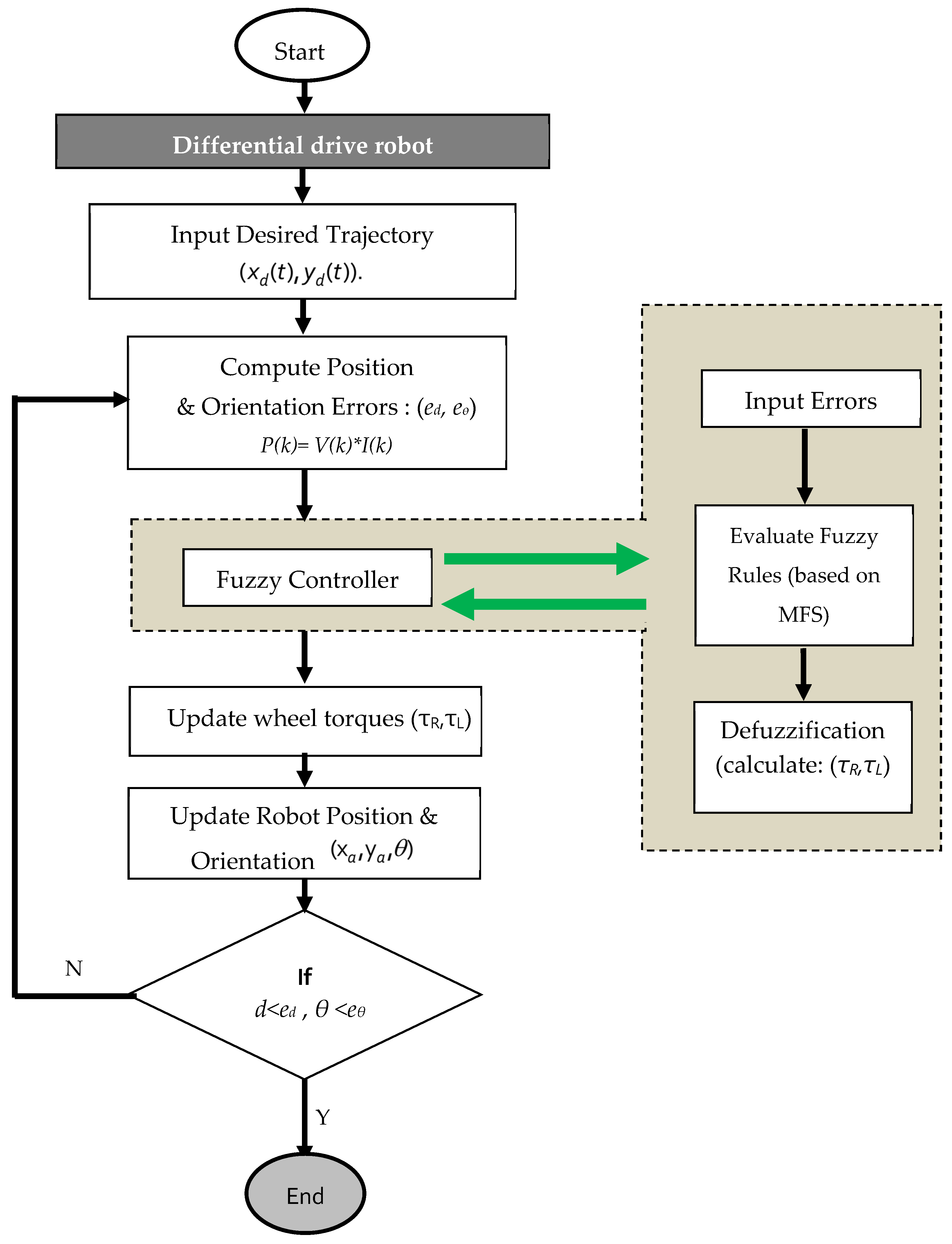
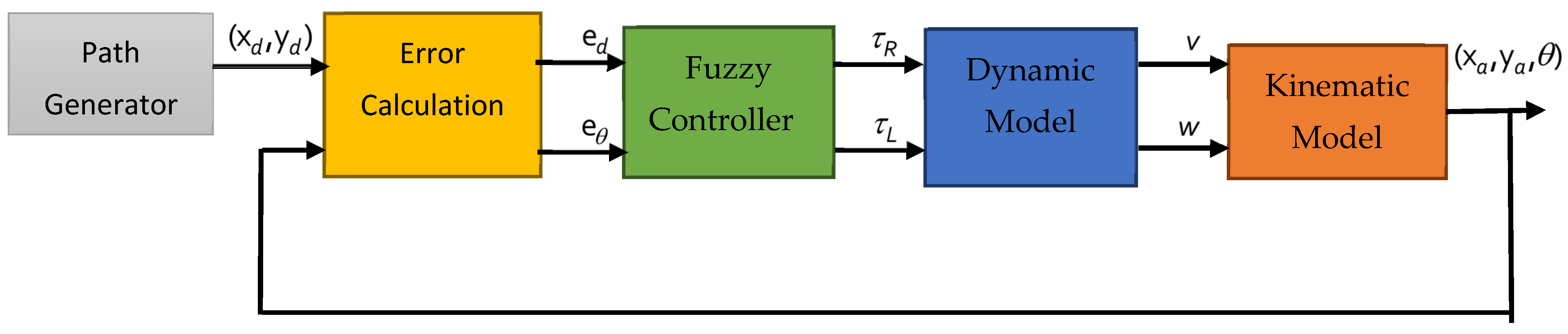
In this work, both type-1 and type-2 fuzzy logic controllers were applied to enable the mobile robot to follow the desired trajectory for comparison purposes. The controller calculates position and orientation errors between the robot’s current state and the target trajectory, then adjusts the right and left wheel torques using fuzzy logic. This process is repeated until the robot reaches the target within the specified error tolerances, ensuring precise trajectory tracking even in the presence of complex paths and errors in the model and parameters.
To ensure a fair and unbiased comparison between the type-1 and type-2 fuzzy logic controllers, strict structural equivalence was enforced. Both controllers were designed with the same number of input and output variables, identical membership function structures with five membership functions per variable, and the same rule base of 25 rules. The shapes, ranges, and distributions of the membership functions were kept identical, and the same scaling factors and normalization ranges were applied.
The parameter tuning process for both type-1 and type-2 fuzzy logic controllers was carried out using the same methodology to ensure a fair comparison. A consistent trial-and-error (heuristic) approach was applied, in which the scaling factors and membership function parameters were adjusted based on the same performance criteria: minimizing trajectory tracking error and achieving smooth control signals. Both controllers were tuned using identical initial parameter ranges and under the same operating conditions. No additional optimization techniques or tuning advantages were applied to either controller, ensuring that the comparison reflects only the inherent differences between the two fuzzy logic approaches. The only difference lies in extending the type-1 membership functions into interval type-2 sets via the introduction of a footprint of uncertainty (FOU), without altering the rule base or increasing the number of rules or parameters. This ensures that the comparison reflects only the impact of uncertainty modeling, rather than differences in controller complexity.
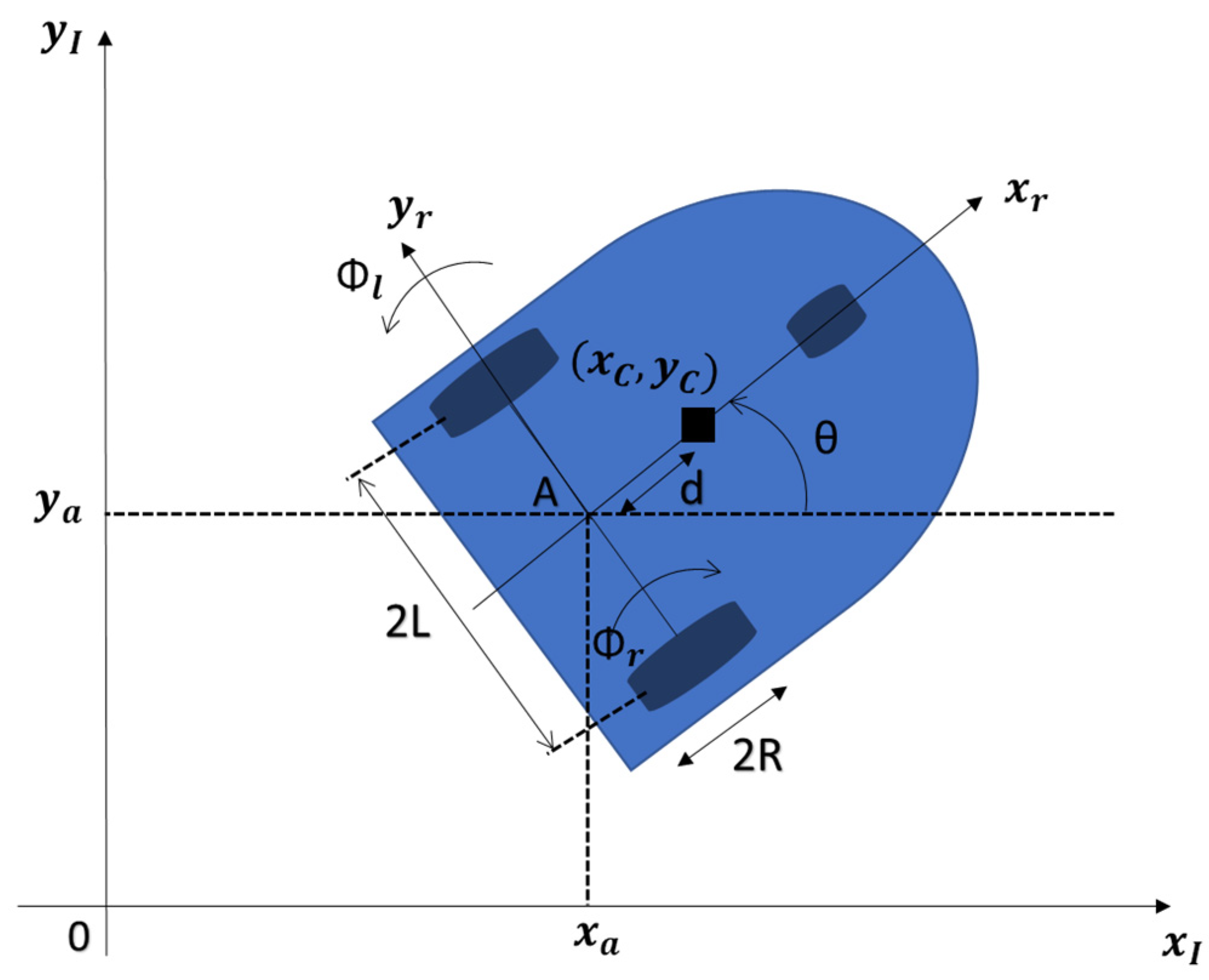
is the error on
x,
is the error on y,
is the distance and the angular error between the robot and the desired trajectory,
is the desired position, and
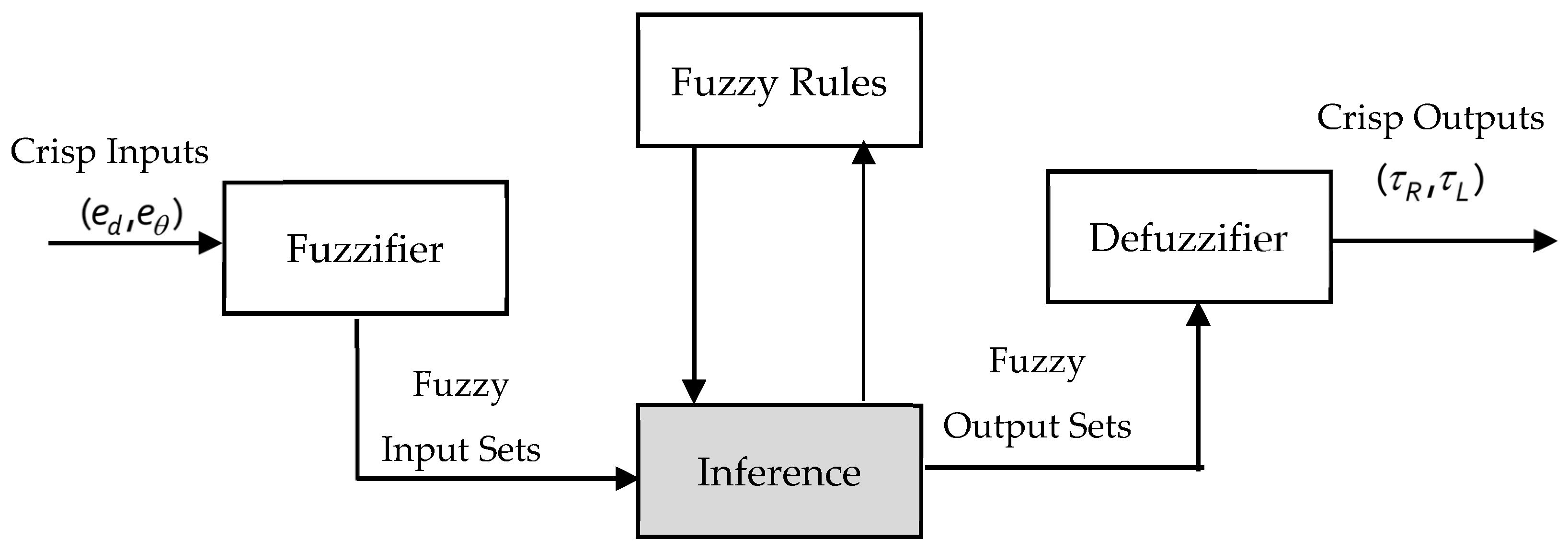
is the position of the robot. We can see the structure of the designed fuzzy controllers applied to a differential drive as shown in the flowchart of
Figure 4.
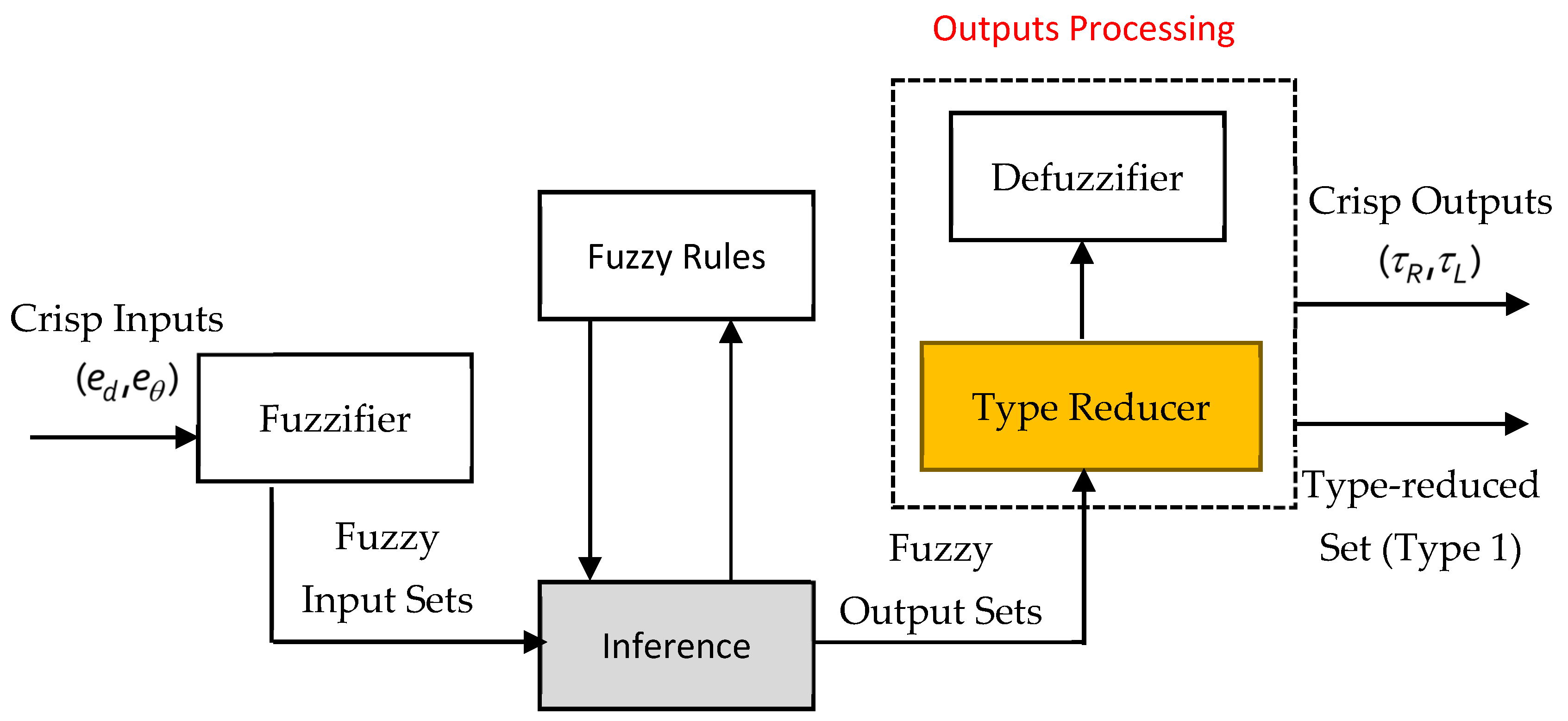
The difference between fuzzy type-1 and fuzzy type-2 lies in the fact that each membership function in type-1 has a single membership degree, whereas in type-2, each value in the membership function is represented by a range of membership degrees [
34]. This allows type-2 to handle a higher level of uncertainty, as the membership functions can contain some degree of error, which type-2 reduces effectively. We can see the difference between them in the following structures presented in
Figure 5 and
Figure 6.
As can be seen in
Figure 5 and
Figure 6, the difference also lies in the presence of the Type Reducer, which converts the fuzzy outputs with uncertain values into a single value that can be used as the final control signal.
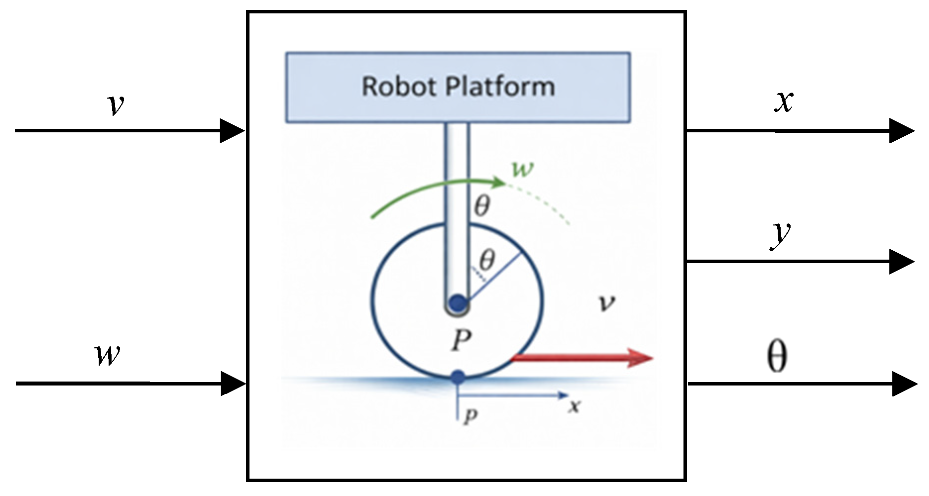
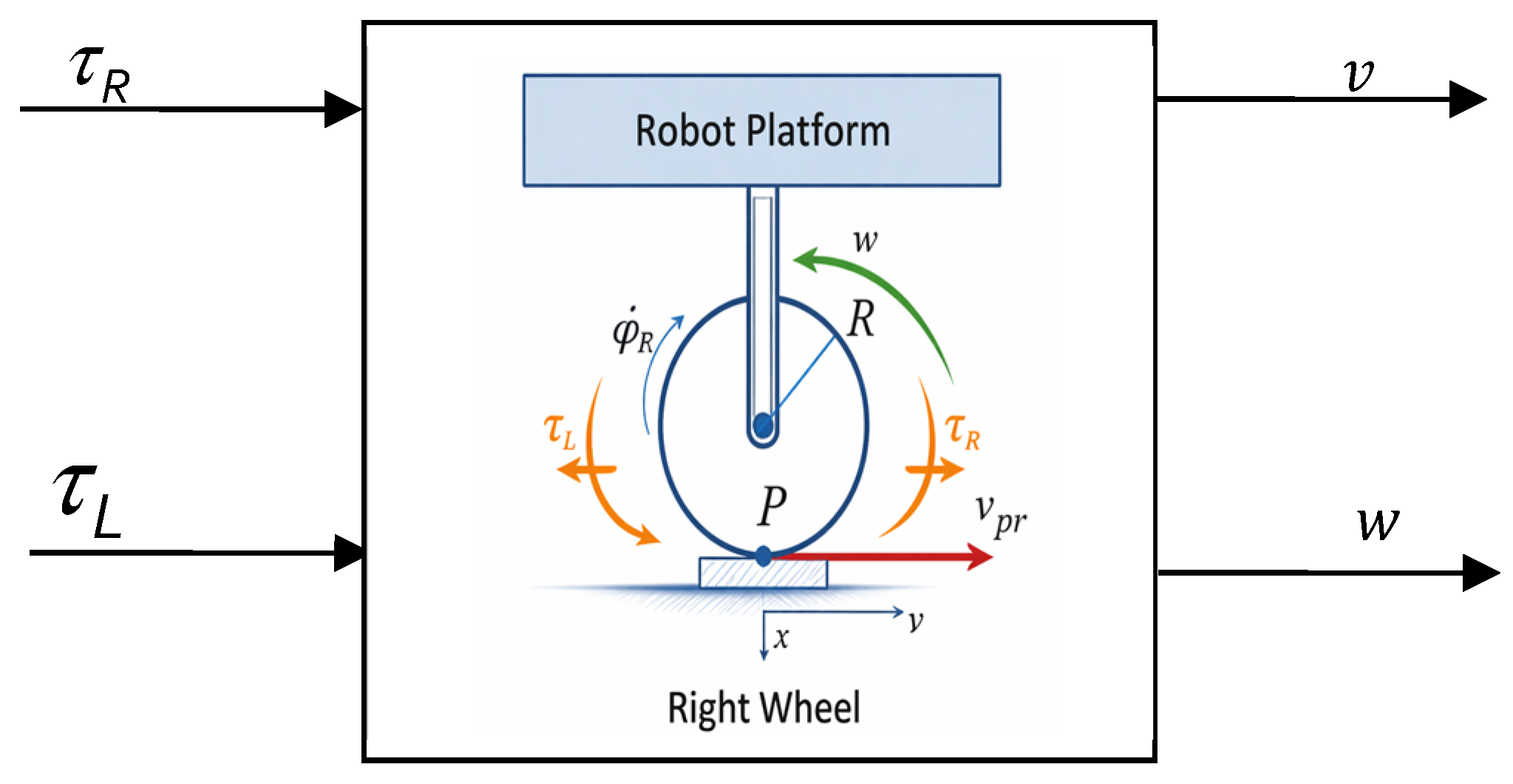
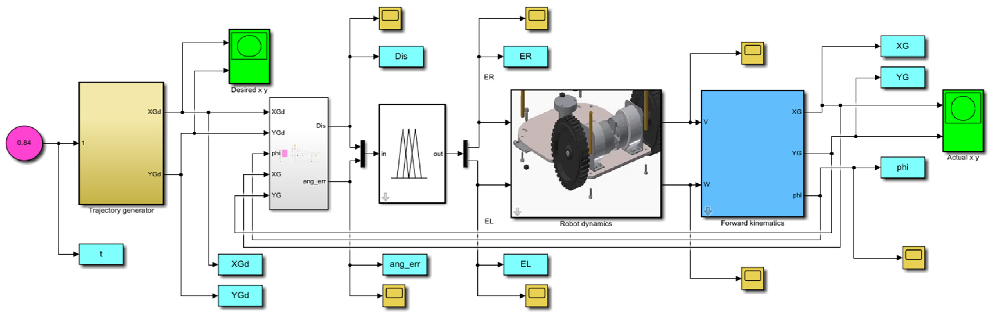
Figure 7 represents the block diagram of the system.
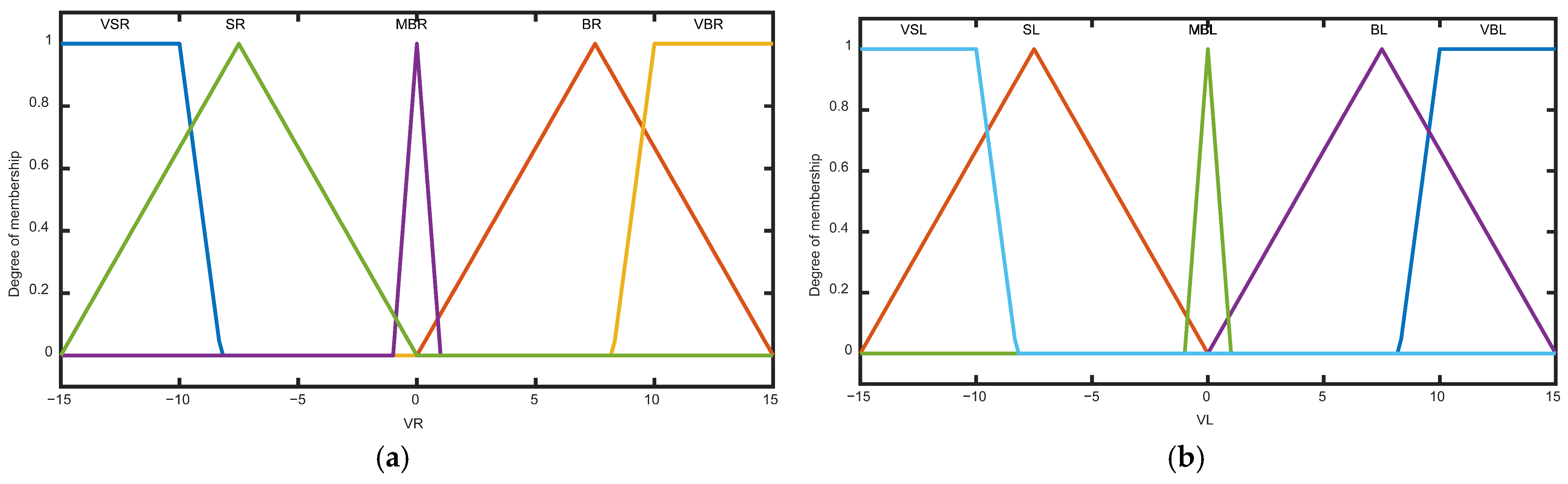
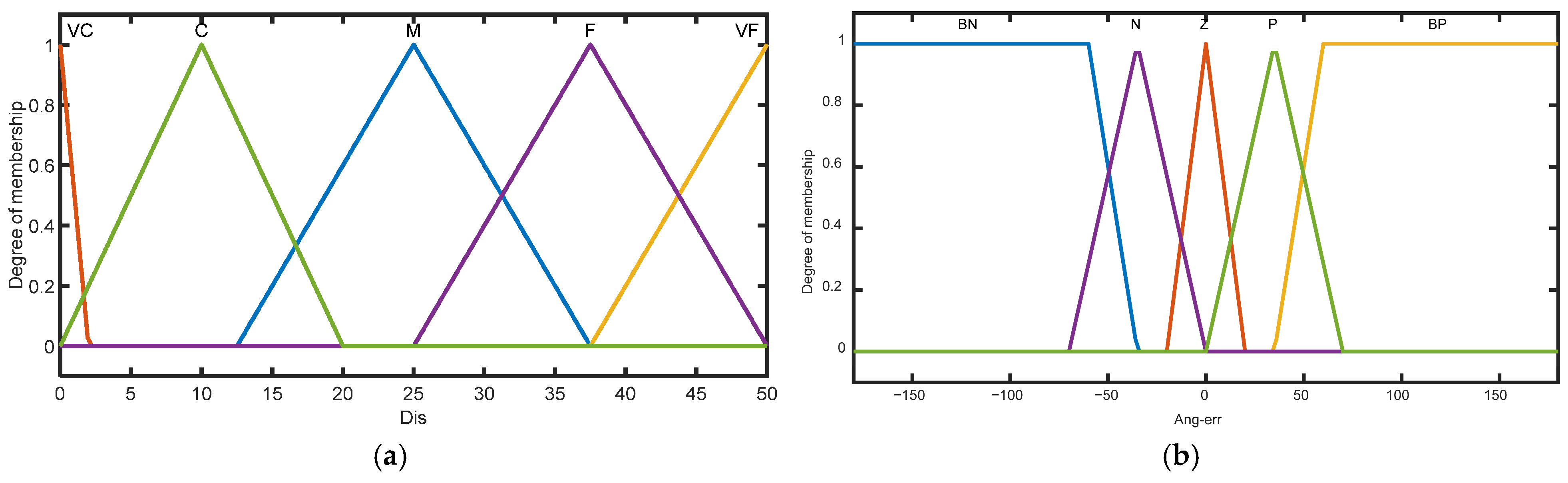
The proposed fuzzy controllers with five membership functions (MFs) have been proposed for the two input variables: distance and angular error. The distance input is categorized as very close (VC), close (C), middle (M), far (F), and very far (VF), covering a range of [0, 50 m]. The angular error input is defined as big positive (BP), positive (P), zero (Z), negative (N), and big negative (BN), within a range of [−180°, 180°]. For the right and left wheel torques, five membership functions were reutilized: very big (VB), big (B), middle (M), small (S), and very small (VS), within the output range of [−15, 15]. For the first controller, we present the membership functions for the input and output in
Figure 8 and
Figure 9.
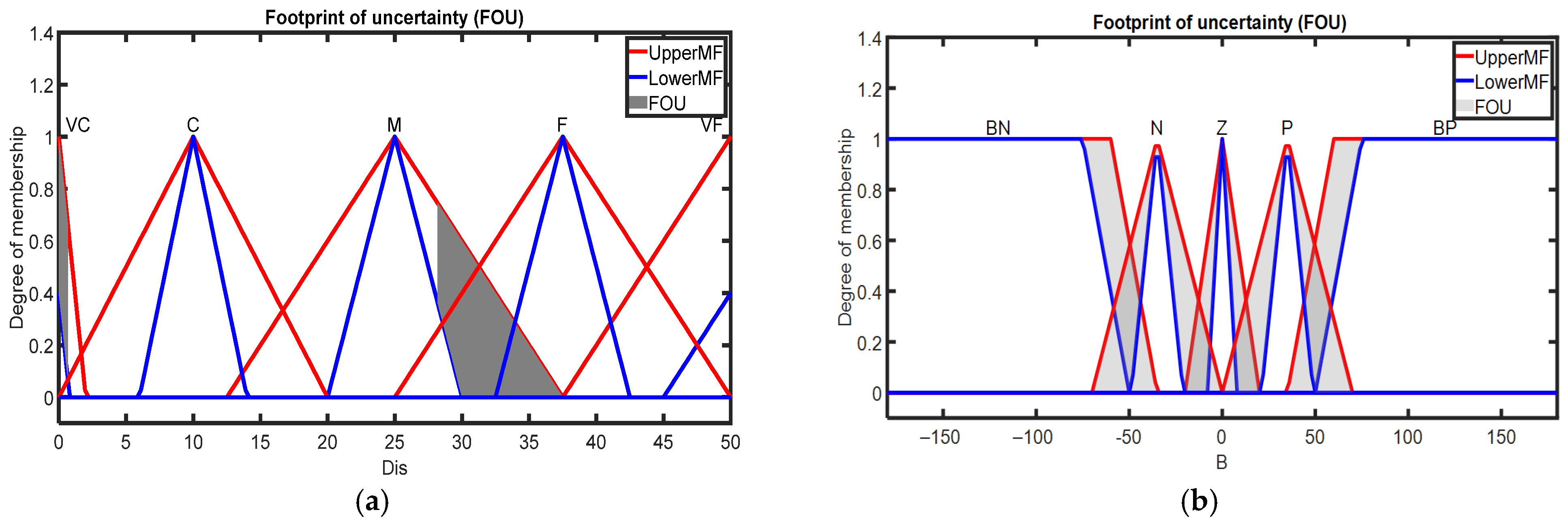
Figure 10 and
Figure 11 present the membership functions of the second FLC.
In this work, triangular and trapezoidal membership functions were employed due to their computational simplicity and efficiency, which makes them particularly suitable for real-time control applications such as mobile robots. This choice ensures faster execution of the fuzzy inference system while maintaining acceptable accuracy in modeling uncertainties.
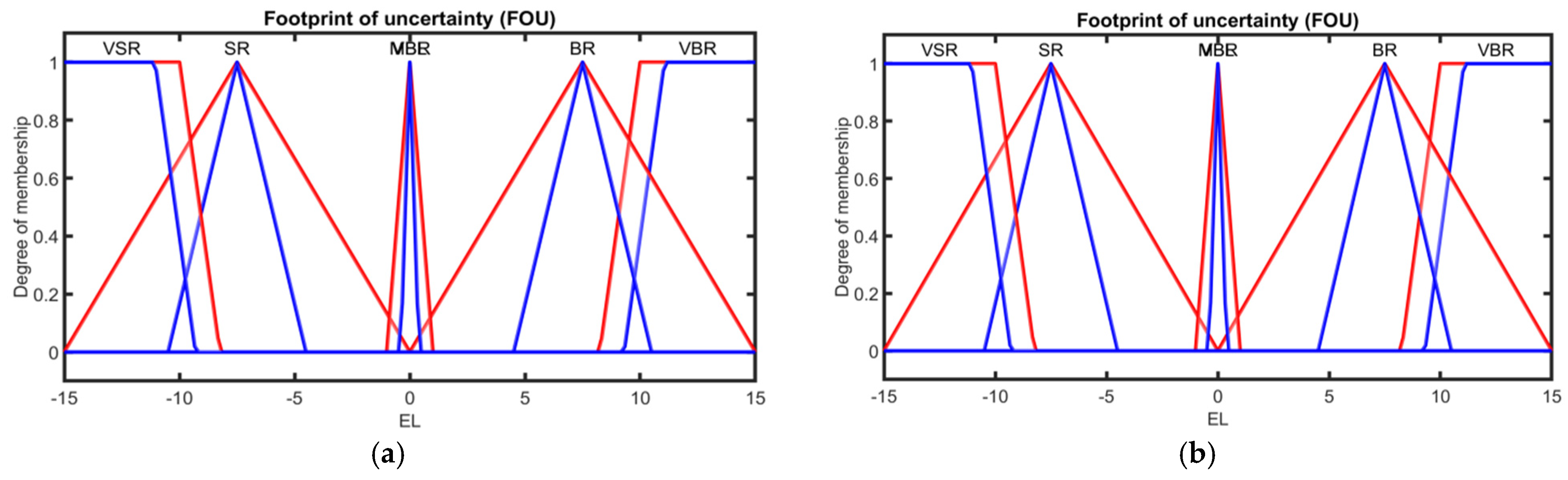
For the type-2 fuzzy logic controller, the same type-1 membership functions were converted into interval type-2 sets. This ensures a consistent and fair comparison framework between the two controllers. A footprint of uncertainty (FOU) was introduced by applying a constant spread of 0.8–0.6 to each membership function, thereby generating the upper and lower MFs that bound the FOU, as shown in
Figure 10 and
Figure 11. After the fuzzy inference step, the type-reduction and defuzzification were performed by the MATLAB 2025 Fuzzy Logic Toolbox, which employs the Karnik–Mendel (KM) iterative algorithm. The final crisp control signal corresponds to the average of the left and right centroids computed by KM. This specification makes the T2FLC design transparent and fully reproducible.
It is important to note that type-2 fuzzy logic controllers generally involve higher computational complexity due to the type-reduction process. In this work, the Karnik–Mendel algorithm was used for type-reduction, providing a good balance between accuracy and computational efficiency for parameter tuning in both type-1 and type-2 fuzzy logic controllers.
Moreover, the relatively small number of membership functions and rules, along with the use of simple membership function shapes, helps maintain a computational load compatible with real-time control requirements.
The fuzzy rule bases are expressed as shown in
Table 1 and
Table 2. They summarize the relationship between inputs and outputs of the DDR.
The fuzzy rule bases for the right and left wheels were intentionally designed differently to account for the distinct roles each wheel plays in the differential drive motion. As is well known, the robot turns to the right when the right wheel’s speed is higher and conversely to the left when the left wheel’s speed is higher. Additionally, when approaching the path or needing to reduce motion, we appropriately decreased the wheel speeds to maintain accurate trajectory tracking and avoid large deviations. By tailoring the fuzzy rules to each wheel in this manner, we ensure optimal control performance and precise trajectory tracking under various conditions. This approach allows each wheel to respond appropriately to its specific influence on the robot’s motion, enhancing stability and robustness. The final, corrected rule bases are presented in
Table 1 and
Table 2, clearly reflecting these differences and facilitating reproducibility.
5. Control Results of the Differential Drive Robot
All simulations were carried out using MATLAB/Simulink in order to ensure controlled and reproducible evaluation conditions for both controllers.
Furthermore, the evaluation is conducted under strictly identical operating conditions, including the same dynamic model, controller structure, parameter settings, and reference trajectories (see
Figure 12). This ensures that the comparison reflects the intrinsic differences between type-1 and type-2 fuzzy logic controllers, rather than variations in tuning or modeling assumptions.
In this section, different path types are simulated and tested to demonstrate the efficiency of the proposed type-1 and type-2 fuzzy logic controllers for accomplishing the path-tracking task. The investigated paths and results are shown in the next subsections. In the simulation, the numerical values of the differential drive robot that have been used are indicated in
Table 3.
5.1. Simple Paths
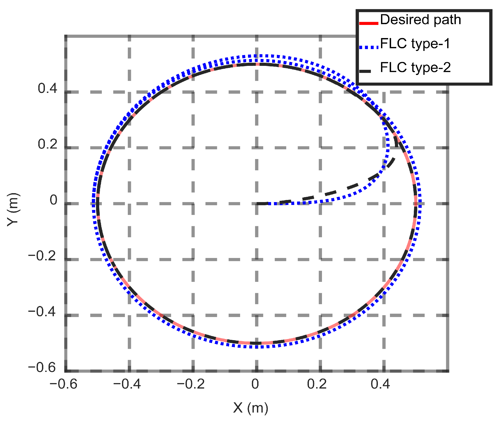
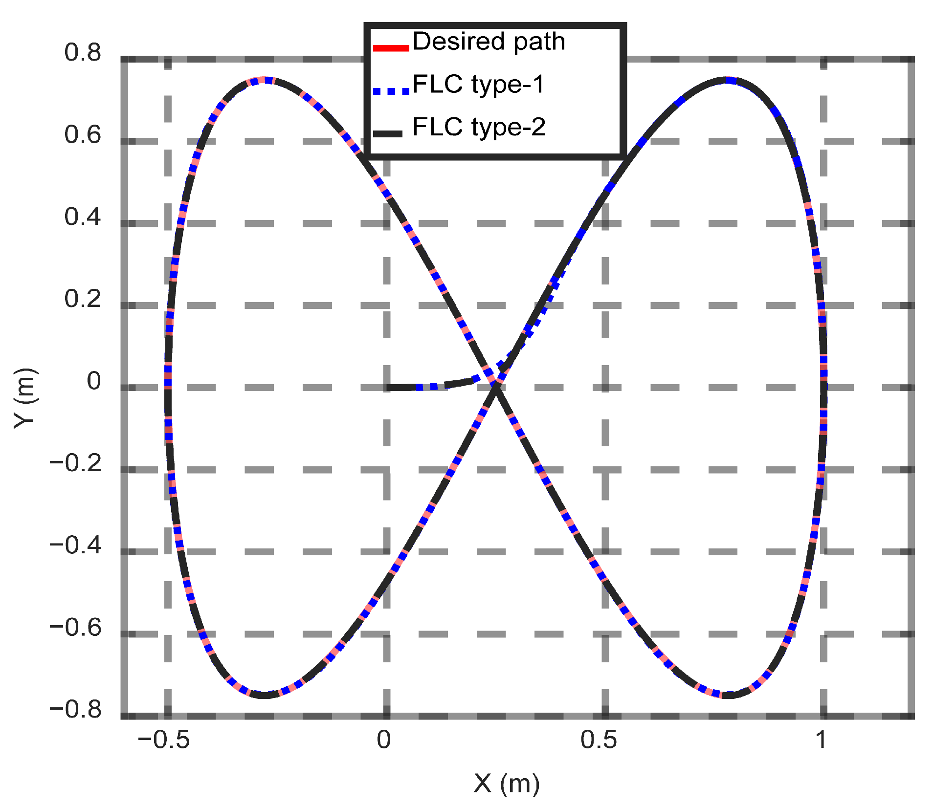
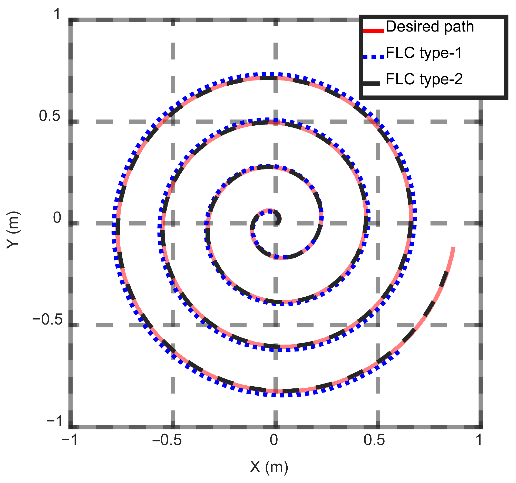
The results are presented as follows, with
Figure 13,
Figure 14 and
Figure 15 illustrating the results for the circular, eight, and spiral trajectories, respectively, with each trajectory accompanied by its corresponding equation.
Table 4 presents the used equations to define the simulated trajectories.
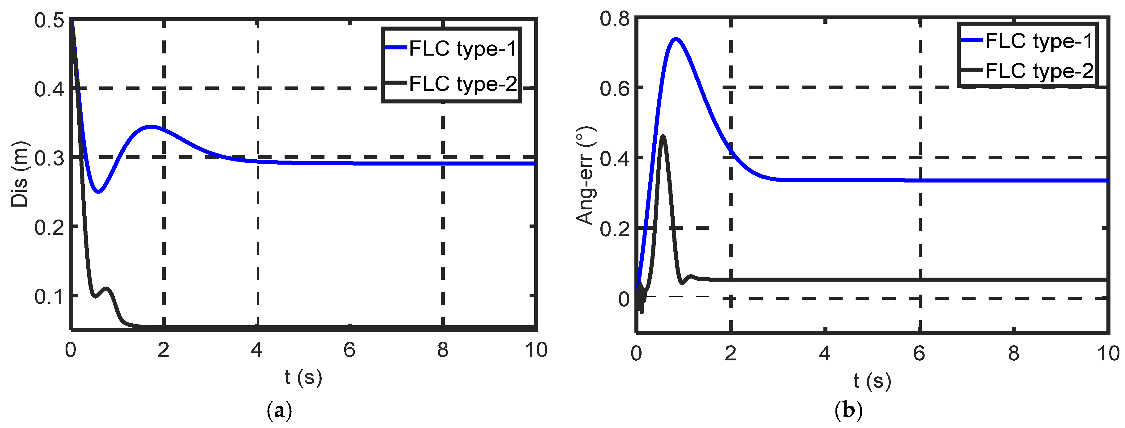
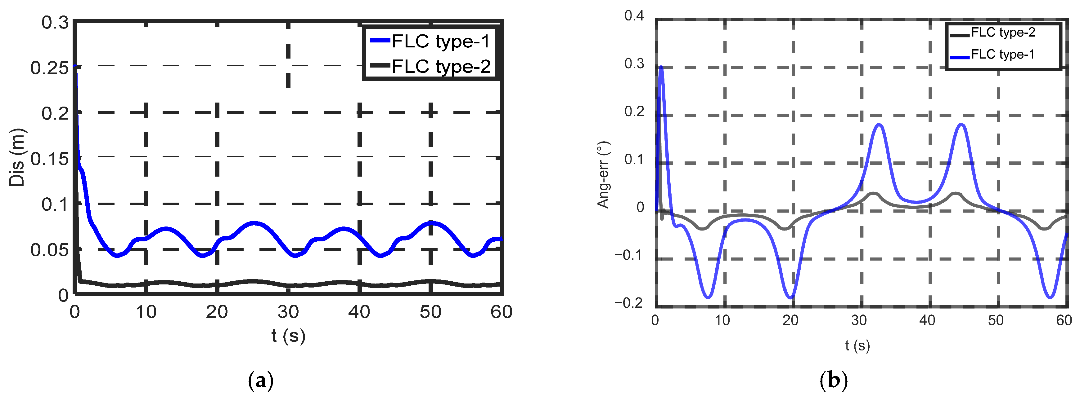
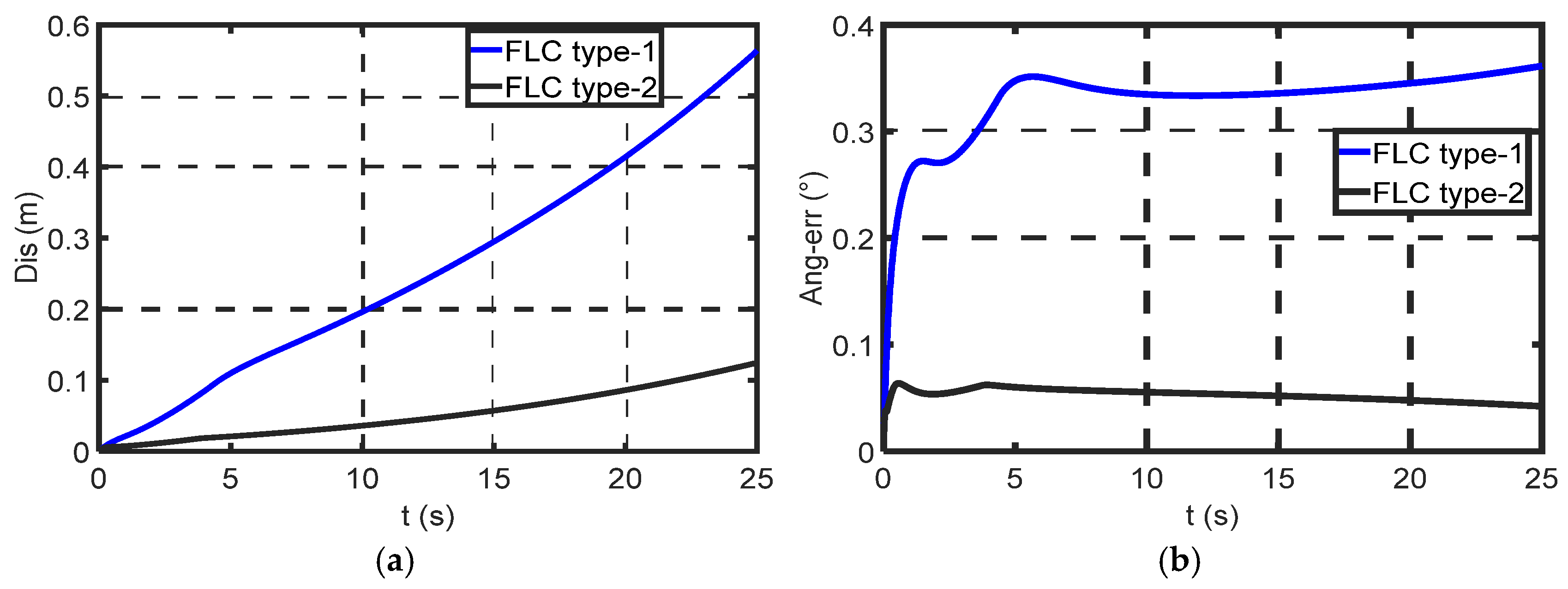
Figure 16,
Figure 17 and
Figure 18 present the distance and angular errors for each trajectory type: circular, eight, and spiral. In this study, we have compared the performance of type-1 and type-2 fuzzy controllers for trajectory tracking of a differential drive robot. We began by testing the system on two simple trajectories: circular and eight paths. The results indicated that both types performed well, with the robot path closely matching both desired trajectories. In the eight-trajectory case, the results were almost identical between the two types. These findings underscore the controller’s effectiveness in achieving highly accurate path tracking, with the difference between fuzzy type-1 and type-2 being minimal, favoring the latter. Additionally, the spiral trajectory results were positive for both controllers, with a slight advantage for fuzzy type-2 in terms of accuracy and overall performance.
We observe an initial error at the beginning of the trajectories, which is attributed to the robot starting from the zero position. However, the robot quickly corrects its path, demonstrating a good response time. This rapid adjustment ensures that the robot aligns accurately with the desired trajectory shortly after its initial movement.
Despite the previously mentioned results showing that both controllers performed well, with a slight advantage for the fuzzy type-2 controller, we observed significant differences in distance and angular errors. The fuzzy type-2 controller demonstrated substantial improvements in both metrics, significantly outperforming the fuzzy type-1 controller. This superiority was particularly evident in the comparison of distance and angular error across the circular, eight, and spiral paths, where fuzzy type-2 consistently delivered near-zero errors.
For the circular trajectory (
Figure 13 and
Figure 16), the type-2 fuzzy logic controller (T2FL) reduced the distance error by 70% (0.09 m vs. 0.30 m) and angular error by 76.9% (0.09° vs. 0.39°) compared to type-1 (T1FL). The response time for the eight-shaped trajectory (
Figure 14 and
Figure 17) was 1.0s for T2FL versus 5.0s for T1FL, demonstrating faster convergence. These improvements are not attributed to differences in tuning or model assumptions, but rather to the inherent capability of type-2 fuzzy logic to handle uncertainty. It is important to note that the observed performance improvement of the type-2 fuzzy controller does not result from an increased number of parameters or a wider tuning range. Both controllers were designed and tuned under identical conditions, with the same structure, rule base, membership functions, and scaling factors.
Therefore, the performance difference can be attributed primarily to the type-2 fuzzy logic controller’s ability to model uncertainty via the footprint of uncertainty (FOU). This capability allows the controller to better handle variations and imprecision in the system, resulting in improved tracking accuracy and robustness.
It should be noted that the reported performance improvements are not based on a single scenario but are consistently observed across multiple trajectory-tracking experiments, including simple, difficult, and complex paths. These improvements reflect general performance trends rather than isolated cases. Although the results presented focus on representative trajectories for clarity, the observed performance gains of the type-2 fuzzy controller were consistent across all tested scenarios, confirming the robustness of the comparison.
These results align with those of Chao et al. [
19], who reported a 30% reduction in RMSE for T2FL in similar nonlinear systems. T2FL’s interval-based membership functions effectively mitigated overshoot during directional transitions, as observed in Yang et al. [
23] for autonomous vehicles. The superior performance stems from T2FL’s “footprint of uncertainty,” which dynamically adjusts rule weights to handle sensor noise and kinematic uncertainties, a limitation of T1FL’s crisp membership functions [
21].
Similar findings have been reported in the literature. For instance, Abut and Salkım [
44] demonstrated that type-2 fuzzy logic controllers significantly outperform conventional PID controllers, achieving error reductions exceeding 90% in complex trajectories. These results further support the effectiveness of type-2 fuzzy logic in handling nonlinearities and uncertainties in mobile robot control.
In addition to average performance metrics, it is important to consider the maximum (worst-case) error to better assess controller robustness. Although the primary focus of this study is on RMSE and response time, the peak deviations can be observed in the error plots (
Figure 16,
Figure 17 and
Figure 18).
These figures show that the type-2 fuzzy controller consistently limits the maximum error compared to the type-1 controller, indicating improved robustness not only in average performance but also in worst-case scenarios.
Compared with existing studies, the performance improvements observed in this work are more consistent across different trajectories, thanks to the controlled benchmarking framework adopted. While several studies report performance gains for type-2 fuzzy controllers, these improvements are often dependent on specific controller structures or tuning strategies.
In contrast, the present study ensures strictly identical conditions between the controllers, allowing a more reliable assessment of their intrinsic differences. This highlights that the observed superiority of the type-2 fuzzy controller is not only significant but also consistent across different scenarios, reinforcing its effectiveness for trajectory tracking applications.
5.2. Difficult Path
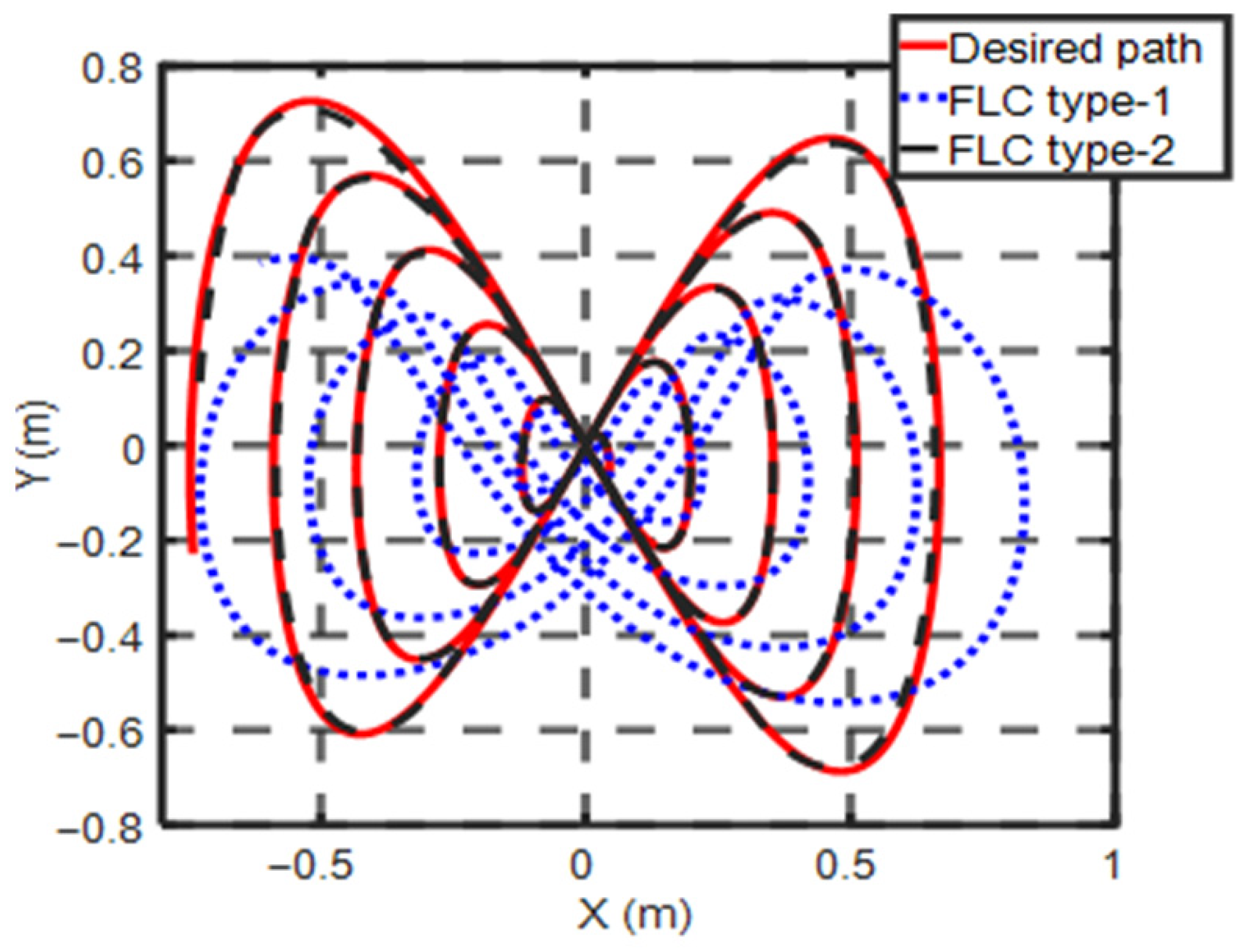
Now, we will test the more complex spiral eight trajectory.
Table 5 defines the equation of this difficult trajectory. The results are shown in
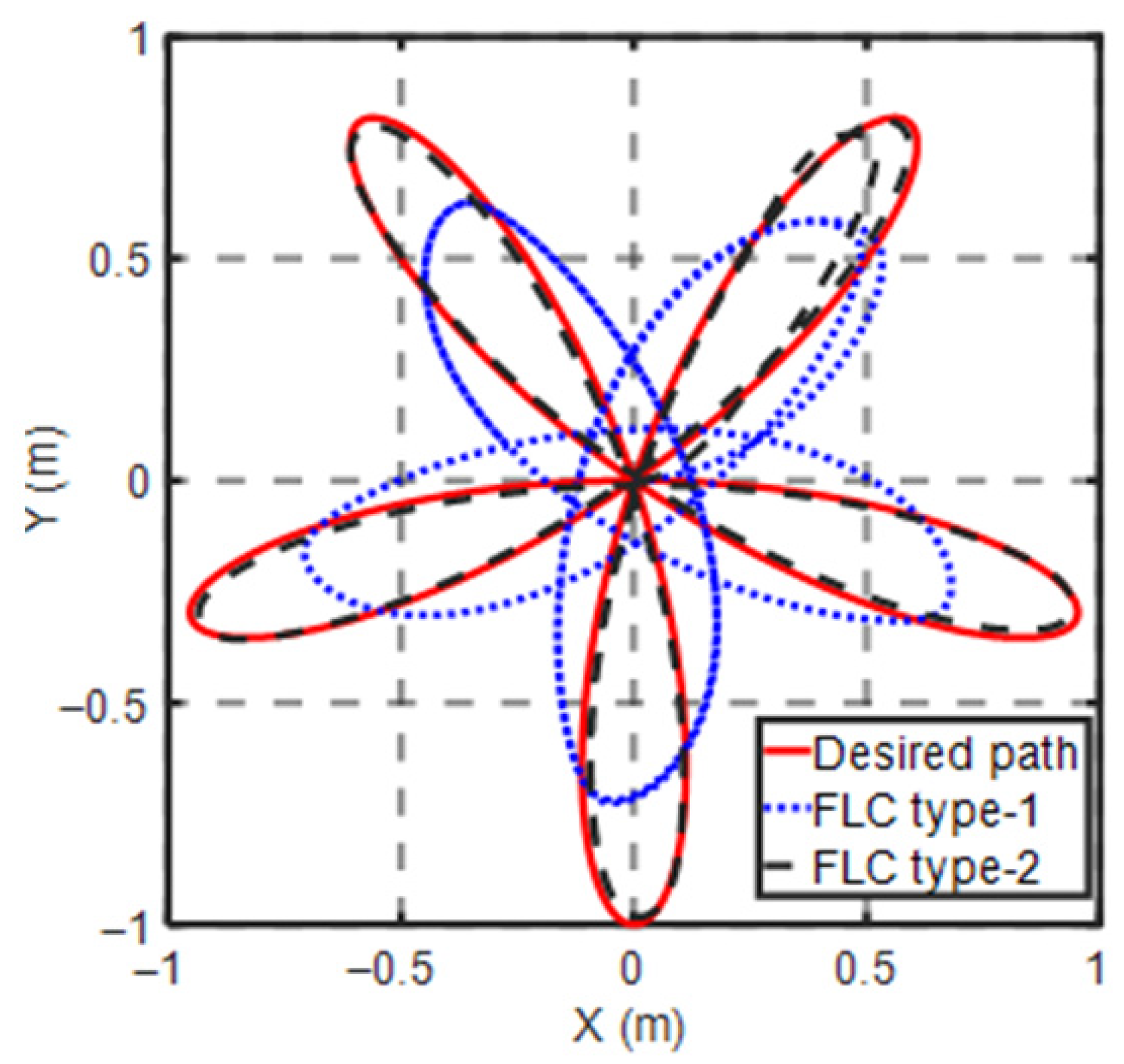
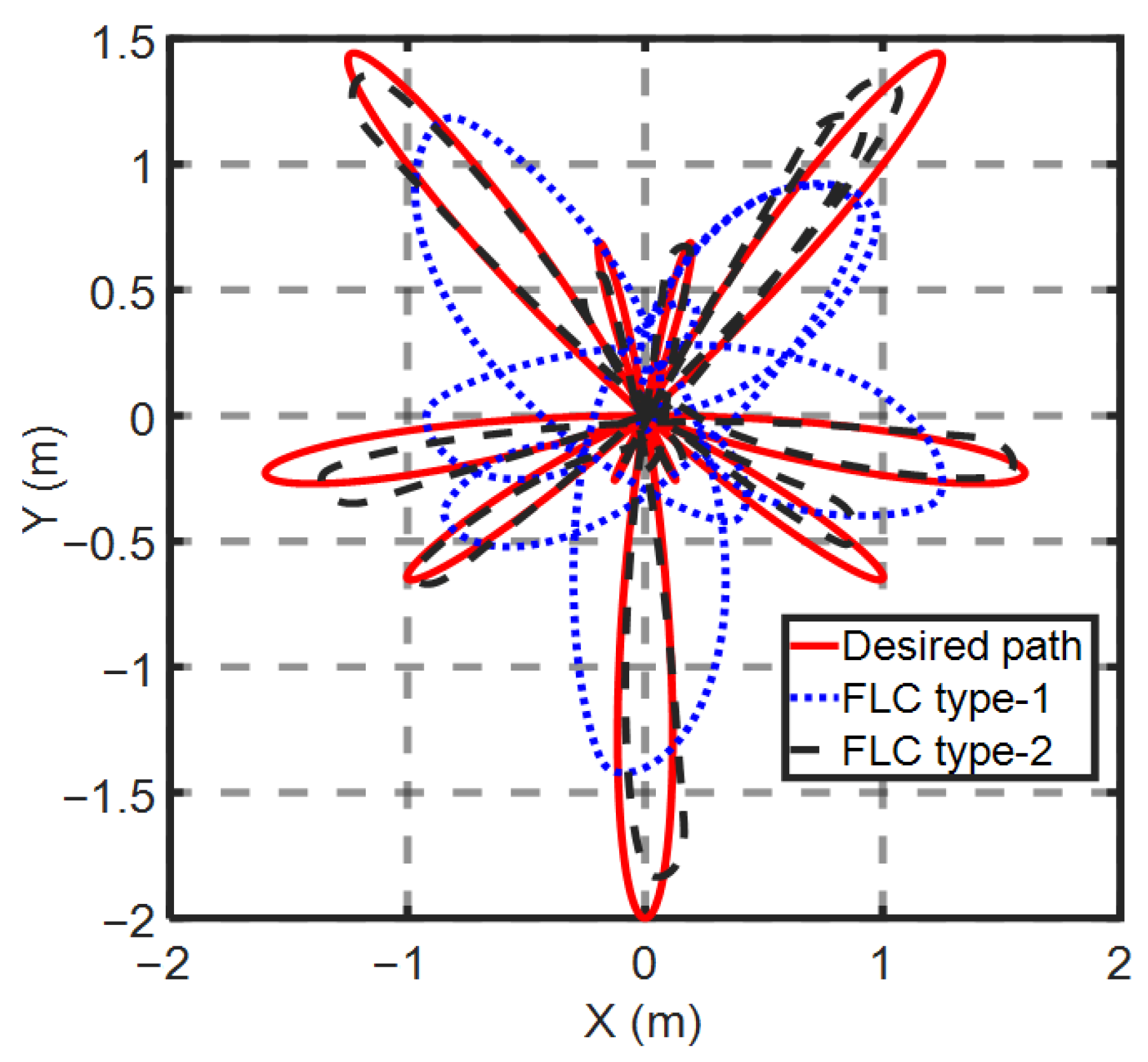
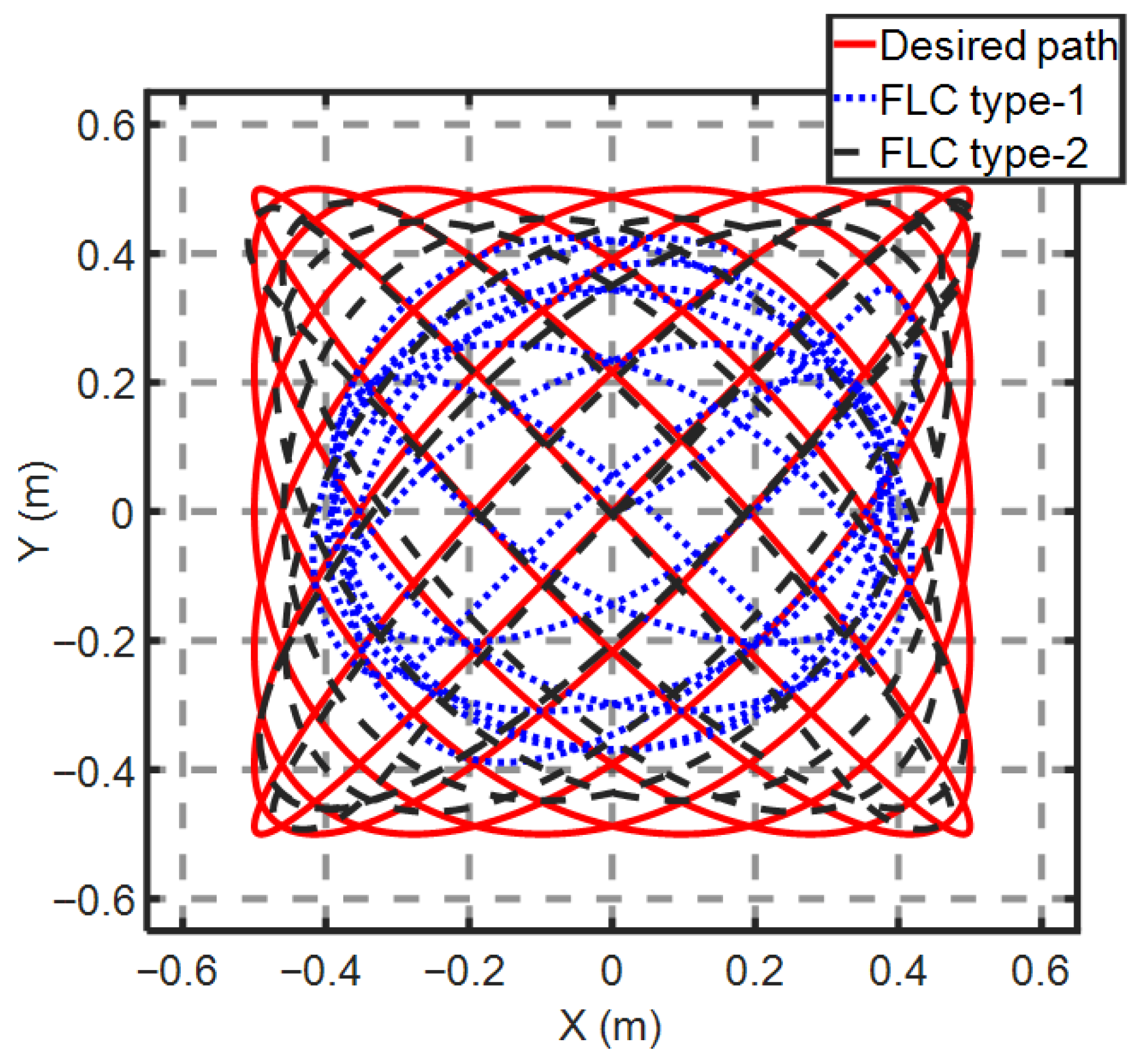
Figure 19. In this trajectory, T1FL failed entirely due to rapid directional changes, while T2FL achieved near-zero errors. Similarly, T2FL maintained robustness on the flower and dragon-fly paths (
Figure 20,
Figure 21 and
Figure 22), with mean errors of 0.26m and 0.21m, respectively.
Table 6 presents the equations for modeling these complex trajectories.
This result aligns with the work of Akmal et al. [
27], who found that T1FL struggled with non-smooth trajectories. T2FL’s layered uncertainty management reduced cumulative errors by 67%, consistent with advancements in industrial robotics [
33]. T2FL’s type-reduction process minimized angular drift by dynamically adjusting torque outputs; this feature is missing in T1FL as presented in [
21]. This adaptability is critical for unstructured environments, as noted in paper [
15].
5.3. Complex Paths
Now, we will test complex trajectories, using the flower path, dragon-fly path, and shape path as modeled in
Table 6. The results are illustrated in
Figure 20,
Figure 21 and
Figure 22. In these tests, we have used two non-standard trajectories, “flower” and “dragon-fly”, to challenge the controllers with sharp and rapid changes in curvature and direction. The “flower” trajectory has been presented in prior studies [
45], while we specifically designed the “dragon-fly” trajectory to stress-test controller performance.
As shown in
Table 7, both fuzzy type-1 and type-2 controllers performed well on simple trajectories, with fuzzy type-2 showing a notable advantage. However, for more complex trajectories, fuzzy type-1 failed to effectively track them. In contrast, fuzzy type-2 demonstrated significant effectiveness across all trajectories, including the more difficult ones, demonstrating superior control over the robot’s dynamic model. This study reinforces the practical importance of type-2 fuzzy control methodologies, offering a compelling case for their broader adoption in mobile robotics and beyond.
To further assess the robustness of the proposed controllers, complex reference trajectories were considered. The type-1 fuzzy controller failed to achieve stable tracking in these demanding scenarios, whereas the type-2 controller maintained accurate performance. The resulting robot paths were almost identical to the desired references, except for the spiral trajectory, which exhibited a small residual tracking error that remains acceptable given the difficulty of the maneuver.
In summary, both type-1 and type-2 fuzzy controllers performed satisfactorily on simple trajectories, with the type-2 design showing a clear quantitative advantage. However, for highly curved and complex paths, the type-1 controller was unable to reliably guide the robot, while the type-2 controller consistently achieved effective tracking across all tested scenarios, highlighting its superior handling of the robot’s nonlinear dynamics. To further interpret these quantitative results in the context of the existing literature, several comparative studies have investigated the relative merits of type-1 and type-2 fuzzy logic controllers for mobile robots and reported that the performance gains achieved by type-2 designs are not always large or universal, but depend strongly on controller structure and tuning mechanisms. For example, Cherroun et al. [
9] have designed type-1 and type-2 Takagi–Sugeno fuzzy controllers for the design of different behaviors of a mobile robot, and their investigation showed that T2FLS has better performance than T1FLS. Benatar et al. [
46] showed that the benefits of type-2 fuzzy control are sensitive to the choice of the footprint of uncertainty, while Linda and Manic [
47] reported mobile-robot scenarios in which type-1 controllers achieved comparable or even better transient responses. These findings highlight that the superiority of type-2 controllers cannot be assumed a priori, whereas the present work demonstrates consistently larger performance improvements in favor of the proposed type-2 controller across both simple and complex trajectories, with reductions exceeding 75% in distance error and 80% in orientation error.
An important aspect of the present study is that both controllers were implemented under strictly identical conditions, including the same nonlinear dynamic model, torque saturation limits, scaling factors, reference trajectories, and baseline rule structures. Consequently, the observed performance gap can be primarily attributed to the intrinsic differences between type-1 and interval type-2 fuzzy logic systems and their respective uncertainty-handling mechanisms, rather than to external factors or unequal tuning. This controlled benchmarking framework enhances the validity of the comparison by eliminating external bias and providing a reliable basis for evaluating and comparing fuzzy-logic paradigms.





 ,
,