Article

Hydrogen Enrichment in Methanol Dual-Fuel CI Engines: A Computational Assessment of Engine Performance and Major Combustion Parameters and Emissions


by
Takwa Hamdi
1,2,
Samuel Molima
1,
Juan J. Hernández
2,*,
José Rodríguez-Fernández
2 and
Mouldi Chrigui
1
1
Mechanical Modeling, Energy and Materials Laboratory, LR24ES23, National School of Engineers of Gabes, University of Gabes, Gabes 6029, Tunisia
2
Escuela Técnica Superior de Ingeniería Industrial, Universidad de Castilla-La Mancha, Av. Camilo José Cela s/n, 13071 Ciudad Real, Spain
*
Author to whom correspondence should be addressed.
Machines 2026, 14(5), 563; https://doi.org/10.3390/machines14050563
Submission received: 25 March 2026 / Revised: 12 May 2026 / Accepted: 15 May 2026 / Published: 18 May 2026
(This article belongs to the Special Issue Advances in Combustion Science for Future IC Engines, 2nd Edition)

Abstract

Hydrogen enrichment of compression ignition (CI) engines has emerged as a promising strategy to simultaneously enhance thermal efficiency and reduce carbon-based emissions. This study numerically investigates how hydrogen enrichment affects engine performance and emissions in methanol–diesel dual-fuel CI engines, a combustion mode gaining increasing attention for replacing fossil diesel with sustainable fuels, particularly in hard-to-abate sectors such as maritime transport. The simulations are based on the Unsteady Reynolds-Averaged Navier–Stokes (URANS) equations, incorporating the RNG k-ε turbulence model, the Eddy Dissipation Concept (EDC) for turbulence–chemistry interaction, and the G-equation for turbulent premixed flame propagation. The numerical model is validated against experimental data for in-cylinder pressure and heat release rate at 45% methanol substitution ratio (by energy). The results indicate that increasing the hydrogen enrichment ratio (HER, defined on an energy basis) from 5% to 20% raises the Sauter mean diameter (SMD) of the diesel fuel from 20.2 µm to 28.0 µm (+38%), driven by reduced aerodynamic breakup intensity associated with modified gas-phase properties under hydrogen enrichment. Furthermore, hydrogen’s elevated adiabatic flame temperature and superior mass diffusivity intensify combustion, raising peak in-cylinder pressure from 75.2 to 79.1 bar (+5.2%), amplifying the peak heat release rate from 129 to 211 J/°CA (+63.6%), and elevating maximum in-cylinder temperature from 1542 to 1735 K (+193 K). Under the investigated CFD operating conditions, these thermodynamic gains translate into an engine-level 6% improvement in indicated thermal efficiency and a 14% reduction in indicated specific fuel consumption (accounting for hydrogen, methanol, and diesel) at HER 20%. On the emissions front, CO2 declines by 24% in direct proportion to the carbon-containing fuel mass displaced by hydrogen substitution, while NOx increases approximately twofold from 0.10 g/kWh at HER 0 to 0.21 g/kWh at HER 20, driven by peak temperature elevation. These findings establish hydrogen-enriched methanol–diesel dual-fuel combustion as a viable pathway toward high-efficiency, low-carbon CI engine operation for heavy-duty transport applications.

1. Introduction

The ongoing global energy crisis, caused by the trade-off between rising energy demands and the growing urgency of mitigating climate change, has intensified the need for sustainable solutions [1]. In hard-to-abate sectors such as maritime shipping and heavy-duty road transport, where full electrification remains technically and economically challenging in the near term, low-carbon fuels integrated into advanced combustion concepts represent the most viable transition pathway [2,3,4]. Among candidate fuels, biodiesel derived from alternative feedstocks has been explored as a sustainable fuel pathway for CI engines. Recent studies have demonstrated advanced optimization frameworks for maximizing biodiesel yield from hybrid Garcinia oils [5]. Other works have also shown improvements in IC engine performance and emissions using ZnO-doped composite biodiesel blends [6]. Alongside biodiesel, methanol has gained significant attention because of its low carbon content, high octane number, inherent oxygen content, and compatibility with existing compression ignition (CI) infrastructure [7,8,9,10]. Methanol is liquid at standard temperature and pressure, miscible with water, and can be produced from renewable feedstocks via green synthesis routes, rendering it one of the most scalable carbon-neutral hydrogen carriers [11,12]. It is also considered a promising e-fuel. Using methanol as a blending fuel for diesel is one of the simplest and most cost-effective methods [13]. Extensive experimental and numerical research has confirmed that methanol–diesel dual-fuel CI operation consistently reduces exhaust emissions and improves thermal efficiency relative to neat diesel, with performance strongly dependent on the methanol substitution ratio and injection strategy [14,15,16,17,18,19]. However, a high substitution ratio tends to extend the ignition delay [19]. Compared with diesel, methanol can be operated under lean conditions due to its higher laminar flame velocity [20].
Hydrogen is an additional compelling fuel candidate owing to its high specific energy (120 MJ/kg), wide flammability range (4–75 vol%), near-zero carbon footprint, and superior laminar flame speed [21,22]. Conventionally, hydrogen is produced via natural gas steam reforming [23] or coal partial oxidation [24], but progress towards green production (including water electrolysis powered by renewables and photo-electrochemical splitting) is accelerating [25]. A particularly relevant production route for engine applications is on-board catalytic steam reforming of part of the methanol, which uses engine exhaust heat to generate a hydrogen-rich reformate gas [26]. This approach is thermodynamically advantageous because it recovers otherwise wasted exhaust enthalpy, avoids the safety concerns and volume penalties of hydrogen storage, and does not introduce an independent third fuel: the hydrogen originates directly from part of the methanol already carried on board. Consequently, in the combustion system studied here, the premixed charge entering the cylinder consists of hydrogen–methanol–air, where hydrogen is a reformate derivative of methanol rather than a separately sourced fuel. This distinction is important for lifecycle assessment and practical implementation, as it preserves a two-tank fuel architecture while enabling hydrogen enrichment benefits. Indeed, on-board methanol reforming has recently been reported as a promising technique to improve overall engine efficiency while mitigating some drawbacks associated with the direct use of methanol, such as its cooling effect under cold engine conditions [27,28].
When hydrogen is added to CI engines under conventional diesel combustion (CDC), significant reductions in CO and particulate matter are observed, accompanied by improvements in thermal efficiency [29,30]. However, the temperature peaks associated with hydrogen’s high adiabatic flame temperature consistently increase NOx emissions [31,32]. The benefits are strongly influenced by factors such as injection timing, EGR rate, and hydrogen fraction [33].
Several studies have examined hydrogen enrichment in dual-fuel CI engines. Yahyaei et al. [34] showed that 12% hydrogen enrichment in a biodiesel/natural gas dual-fuel engine reduced unburned hydrocarbons by 40%, lowered carbon monoxide, shortened the ignition delay from 10.5 to 9.3 CAD, and increased thermal efficiency. Bayramoğlu et al. [35] demonstrated that hydrogen addition improved the energy and exergy efficiency of a biodiesel–diesel–hydrogen engine, with the highest thermal and exergy efficiencies reaching 30.5% and 28.5%, respectively, particularly at intermediate engine load. Fakhari et al. [36] studied the effects of hydrogen enrichment in ammonia/diesel combustion within a Reactivity Controlled Compression Ignition (RCCI) engine. The findings showed that hydrogen enrichment improved combustion efficiency and enhanced the indicated mean effective pressure, while simultaneously decreasing NOx, CO, HC, unburnt ammonia, and N2O emissions. Ahmadi et al. [37] numerically investigated the effects of hydrogen addition under CDC and RCCI combustion in a Caterpillar 3401 heavy-duty diesel engine. The results indicated that hydrogen addition in RCCI combustion improved combustion efficiency and reduced emissions, except for NOx. However, adding hydrogen to diesel led to knock when it contributed more than 60% of the total energy.
While methanol–diesel dual-fuel compression ignition (CI) combustion has been explored, and hydrogen enrichment has been extensively studied in dual-fuel CI systems, primarily involving diesel/biodiesel as high-reactivity fuels and natural gas or ammonia as low-reactivity, port-injected fuels, the specific impact of hydrogen addition in methanol–diesel dual-fuel configurations remains unexplored. The novelty of this work is therefore twofold: it provides a CFD-based investigation of hydrogen enrichment in a methanol–diesel dual-fuel CI engine, and it explicitly quantifies the effect of hydrogen enrichment on diesel spray atomization and vaporization in this specific dual-fuel environment. To the authors’ knowledge, these coupled spray–combustion effects have not been systematically quantified for hydrogen-enriched methanol–diesel dual-fuel CI combustion. Although methanol is not typically associated with fuel slip issues, unlike natural gas or ammonia (problems that hydrogen enrichment can help mitigate), it is documented that methanol’s strong cooling effect can significantly increase unburnt hydrocarbon emissions, particularly at low engine loads [21,38]. Among these emissions, highly reactive oxygenated species, such as aldehydes and ketones, may play a critical role in atmospheric chemistry [39]. In this context, hydrogen enrichment could offer a promising pathway to alleviate these drawbacks by enhancing combustion efficiency. This approach becomes especially attractive considering that, as previously commented, hydrogen could be produced on-board via reforming of methanol using exhaust gas heat. Notably, methanol reforming requires substantially lower temperatures than those needed for methane or ammonia, enabling effective operation across a broader engine load range. In addition, methanol substitution reduces the energy density (by mass) of the mixture relative to neat diesel operation owing to methanol’s low LHV; hydrogen enrichment is therefore investigated as a targeted strategy to recover this energy deficit while preserving the carbon reduction benefits of the methanol–diesel system. Adding hydrogen to this charge creates a fundamentally different interaction. In the methanol–diesel baseline, the premixed charge already contains methanol, a fuel with an inherent oxygen content and a higher laminar flame speed. Adding hydrogen to this already oxygen-bearing, fast-burning mixture amplifies a reactivity level that does not exist in conventional diesel engines, producing interactions in spray atomization, equivalence ratio distribution, and reaction zone topology that differ qualitatively from those observed when hydrogen is added to a pure diesel charge. This study addresses a gap in the open literature, as the combined effects of hydrogen enrichment on spray atomization, combustion characteristics, and emissions in a methanol–diesel dual-fuel CI engine have not been previously investigated. The objective of this study is to investigate, via three-dimensional URANS-based CFD simulations, the effects of hydrogen enrichment ratio (HER = 05, 10, 15, 20 on an energy basis) on (i) diesel spray atomization and vaporization characteristics; (ii) OH radical distribution and flame propagation topology; (iii) in-cylinder pressure, heat release rate, and peak temperature; and (iv) engine performance and emissions. The hydrogen is treated as premixed with the incoming methanol–air charge prior to the intake valve closing. The findings are intended to provide quantitative guidance for the design of high-efficiency, low-carbon dual-fuel CI engines in maritime and heavy-duty applications.

2. Numerical Setup

2.1. Flow and Combustion Modelling

The numerical study is performed using ANSYS Forte 2023 R2 under academic license. The physical configuration is based on a single-cylinder AVL 580 engine (AVL List GmbH, Graz, Austria) [14,22], whose specifications are summarized in Table 1. The fuel delivery architecture comprises two injection events: a pilot injection delivering 15% of the total fuel mass through a common-rail direct injector, followed by a main injection of the remaining 85%. Methanol is supplied via port fuel injection, premixed with the intake air. Hydrogen is introduced as a premixed component in the intake charge. It is important to note that the numerical model was first validated against experimental data at a methanol substitution ratio of 45% by energy; hydrogen was subsequently introduced parametrically across four enrichment levels (HER = 05, 10, 15, and 20) while keeping the diesel and methanol flow rates unchanged. The hydrogen enrichment ratio (HER) is defined as the percentage of hydrogen energy ratio relative to the total fuel energy input [40]:
HER   =   m ˙ H L H V H m ˙ D L H V D + m ˙ M L H V M 100 %
where m ˙ is the mass flow rate, and L H V   is the lower heating value of each respective fuel.
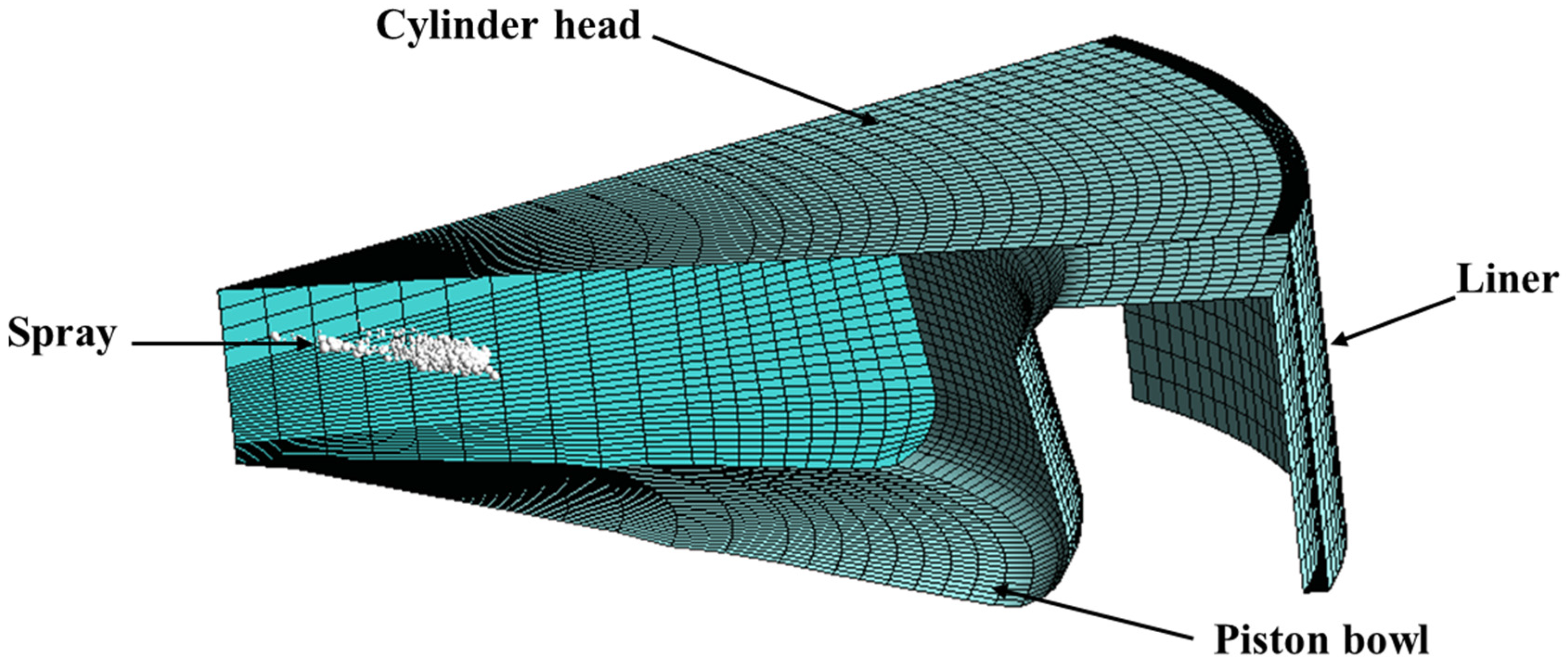
A high-pressure-cooled EGR system is incorporated at 7.5% EGR ratio across all cases. The computational domain is a 45° sector of the full cylinder geometry, encompassing the cylinder volume and piston bowl (Figure 1). Featuring eight holes, the injector operates within a domain assumed to be axisymmetric. The analysis is restricted to the period when both valves remain closed, extending from 148° BTDC (IVC) to 130° ATDC (EVO). Initial and boundary conditions are listed in Table 2.
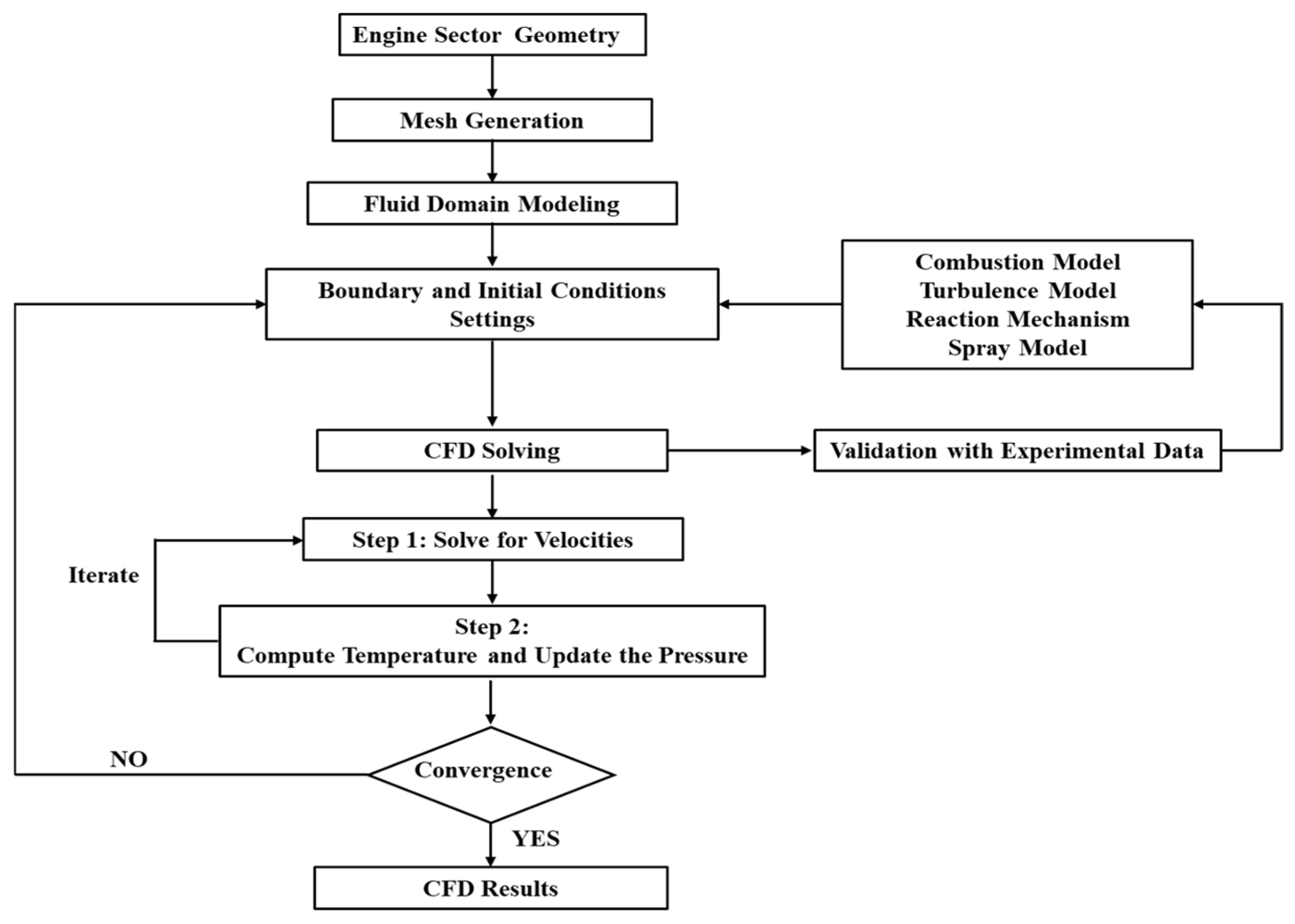
The flow field is modeled using the Unsteady Reynolds-Averaged Navier–Stokes (URANS) framework, where the continuity, momentum, energy, and species transport equations are ensemble-averaged over turbulent fluctuations. Pressure–velocity coupling is resolved with the SIMPLE algorithm, which iterates between extrapolated pressure fields and velocity/temperature corrections until convergence is reached at each crank-angle time step. This iterative correction is necessary because the pressure at the new time level depends on both velocity and density fields derived from that same pressure. Figure 2 depicts the methodology used in the numerical simulation.
Turbulence is modelled using the Renormalization Group k-ε (RNG k-ε) model, which is preferred over the standard k-ε formulation for engine in-cylinder flows due to its improved capability for handling high strain rates [41]. Ignition kernel growth is modelled using the discrete particle approach of Tan and Reitz [42], in which the flame front is tracked as a Lagrangian particle. Once ignition is established, the turbulent flame surface density is determined from particle concentration within each computational cell, and flame propagation is governed by the G-equation model [43,44,45,46]. The G-equation partitions the flow domain into burned and unburned regions via a level-set scalar G, with G = 0 defining the instantaneous flame surface. The local turbulent flame speed is coupled to the laminar flame speed through the Peters [43] framework, which distinguishes corrugated-flamelet and thin-reaction zone regimes depending on the ratio of the Kolmogorov length scale to the laminar flame thickness. The laminar flame speed is computed using the Gülder correlation [47,48]:
S L ,   r e f 0 =   ω φ η e ξ ( φ σ ) 2
here ω , η , ξ, and σ are empirical parameters derived from experimental data in [42,43]. The turbulent flame speed within the G-equation is evaluated as:
S T 0 S L 0 = 1 + I P   a 4 b 3 2   l I 2 b 1   l F + a 4 b 3 2   l I 2 b 1   l F 2 + a 4 b 3 2   u l I S L 0   l F 1 2
where I P represents a progress variable, l I and l F refer to the turbulence integral length scale and the laminar flame thickness, respectively, and constants b 1 , b 3 , and a 4 are calibrated by Peters [43]. The turbulence–chemistry interaction is modelled using the Eddy Dissipation Concept (EDC), implemented in ANSYS Forte through the Turbulence Chemistry Interaction (TCI) model linked to ANSYS Chemkin-Pro solver 2023 R2 [49,50]. The effective species production rate accounts for the fact that chemical reactions occur in fine-scale turbulent structures, introducing a mixing time scale τ m i x that competes with the chemical time scale   τ c h e m
τ e f f =   τ c h e m + τ m i x
ω ˙ ~ k , e f f t = Y ~ k n + 1 Y ~ k n = τ c h e m ω ˙ ~ k t τ e f f = τ c h e m Y ~ k k i n Y ~ k n τ c h e m + τ m i x
where Y ~ k n and Y ~ k n + 1 represent the species mass fraction at the current and next time steps, respectively, and Y ~ k k i n denotes the species mass fraction predicted by chemical kinetics.
A detailed reaction mechanism comprising 425 species and 3128 reactions is employed. n-heptane has been used as a diesel fuel surrogate. It is sourced from the ANSYS Model Fuel Library 2023 R2. The validation of this mechanism has been demonstrated under constant pressure conditions across a range of fuel mixtures [49]. The Kelvin–Helmholtz/Rayleigh–Taylor (KH-RT) hybrid model is employed to simulate spray atomization and droplet breakup within the solid-cone spray. Within the breakup length from the nozzle exit, the KH model is employed to describe primary breakup, while the RT model accounts for secondary breakup [50]. Additionally, spray droplet vaporization is represented using the Discrete Multi-Component (DMC) vaporization approach. It tracks individual fuel droplets throughout the evaporation process and enables coupling with the reaction kinetics of specific fuel components. This model assumes spherical liquid fuel droplets and analyzes only cold flow physical parameters, excluding chemical reactions [51].

2.2. Mesh Sensitivity Analysis

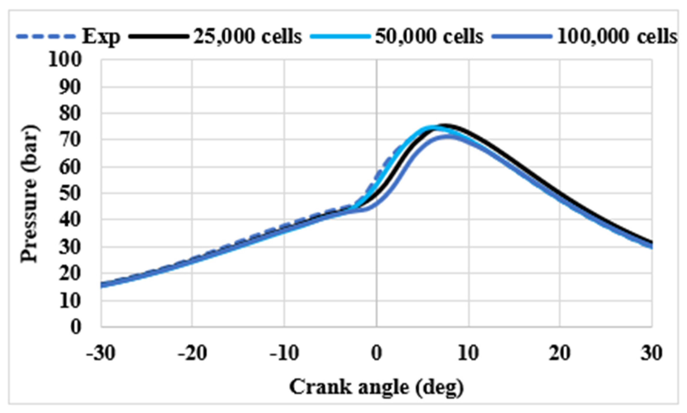
The mesh dependency analysis is performed under specified operating conditions. The operating conditions include an engine speed of 1600 rpm and an indicated mean effective pressure (IMEP) of 5.2 bar. These analyses ensure consistency and reliability in assessing numerical accuracy. Three mesh densities were assessed: 25,000, 50,000, and 100,000 cells (Figure 3). The 50,000-cell mesh was selected as the optimal compromise between solution fidelity and computational cost. The 25,000-cell mesh produces acceptable results but marginally under-resolves the spray-flame interaction zone near TDC. In contrast, the 100,000-cell mesh slightly underpredicts the in-cylinder pressure throughout the compression and combustion phases. The finest resolution did not improve agreement with experimental data and introduced increased numerical stiffness in spray–turbulence interaction regions. This behavior is attributed to the interaction between refined spatial resolution, stiff source terms in the spray sub-models, and the limitations of the URANS framework, where further grid refinement does not necessarily translate into improved physical fidelity. The mesh of 50,000 cells closely reproduces the experimental pressure trace, particularly near TDC, where combustion is most sensitive to spatial resolution.

2.3. Time-Step Sensitivity Analysis

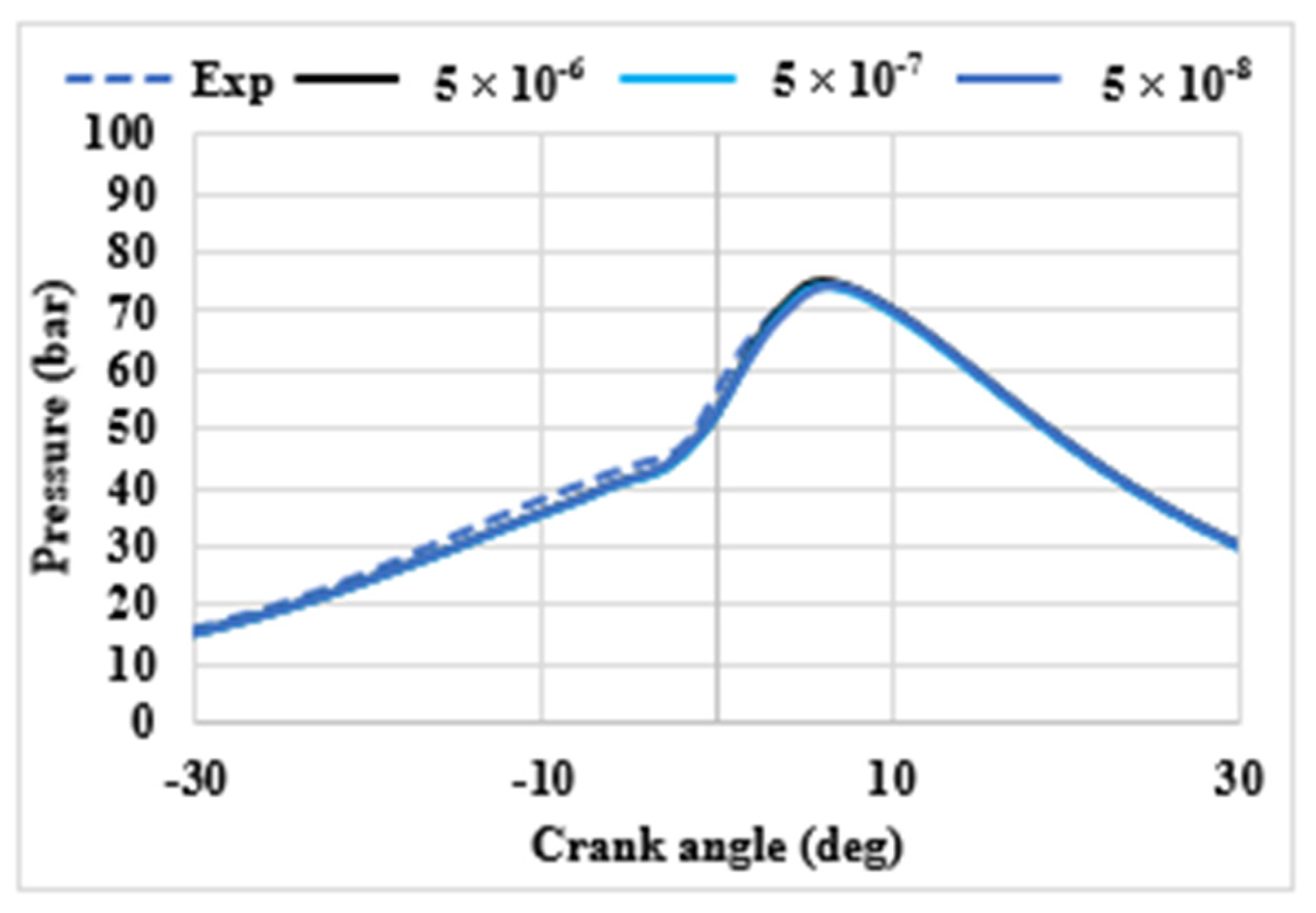
To ensure the temporal accuracy and numerical stability of the combustion process, a time-step sensitivity study was conducted by comparing three different time-step values: 5 × 10⁻⁶ s, 5 × 10⁻⁷ s, and 5 × 10⁻⁸ s. The in-cylinder pressure traces obtained from each simulation were evaluated against experimental measurements. As illustrated in Figure 4, all three time-step configurations produced nearly identical pressure profiles throughout the entire crank angle range, demonstrating that the numerical solution is well converged and exhibits low sensitivity to temporal discretization. The experimentally measured peak in-cylinder pressure was 74.2 bar, while the simulations yielded peak values of 74.8 bar, 74.4 bar, and 73.9 bar for time steps of 5 × 10⁻⁶ s, 5 × 10⁻⁷ s, and 5 × 10⁻⁸ s, corresponding to relative RMSEs of 0.81%, 0.27%, and 0.40%, respectively. These results confirm that the intermediate time step of 5 × 10⁻⁷ s yields the closest agreement with the experimental peak pressure, with a deviation of only 0.2 bar (0.27%), while the coarsest time step of 5 × 10⁻⁶ s introduces slight overprediction attributable to numerical diffusion associated with larger time increments. Notably, further refinement to 5 × 10⁻⁸ does not improve predictive accuracy, as it marginally underpredicts the peak pressure by 0.3 bar (0.40%), suggesting that the solution has reached temporal convergence at 5 × 10⁻⁷ s. Accordingly, a time step of 5 × 10⁻⁷ was selected for all subsequent simulations in this study, as it provides an optimal balance between computational efficiency and solution accuracy.

2.4. Validation and Case Study

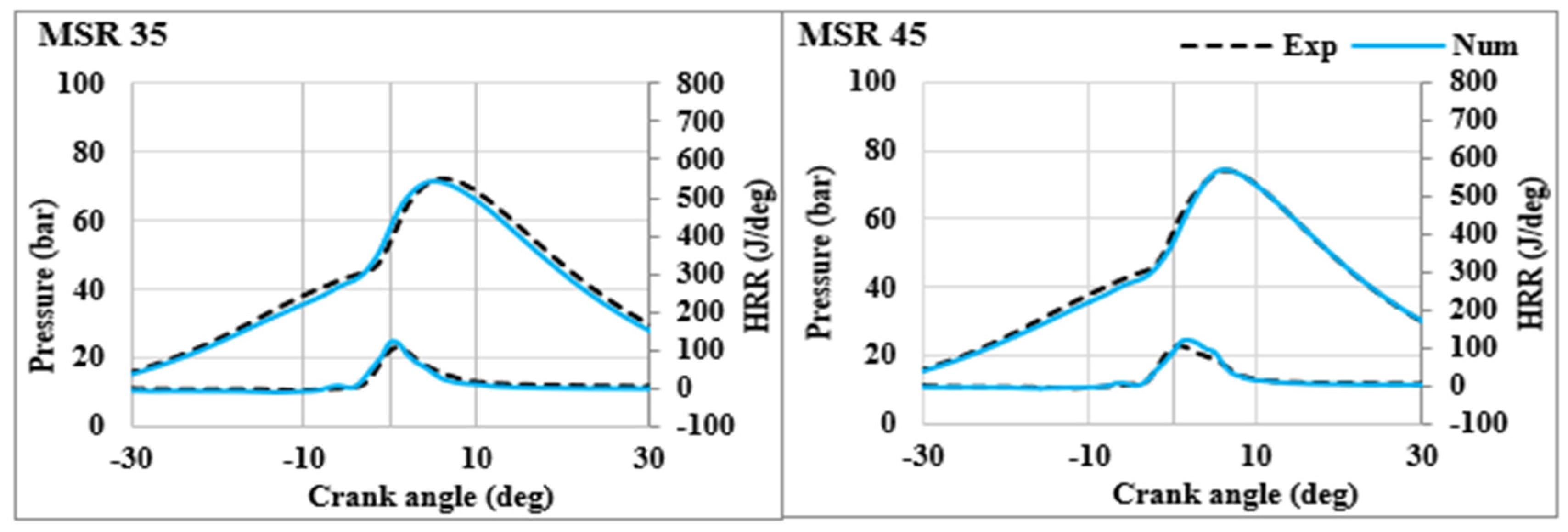
Figure 5 presents the numerical validation of in-cylinder pressure and heat release rate (HRR) for methanol–diesel dual-fuel combustion. In this configuration, diesel is directly injected into the combustion chamber, while methanol is supplied via port fuel injection. The validation corresponds to a methanol substitution ratio of 35% and 45%. The experimental data used for validation were obtained from the work of Domínguez et al. [38]. In the original experimental work, each test was replicated twice and conducted randomly to evaluate the repeatability of the test bench and measuring equipment. Operational constraints were imposed to ensure safe and stable combustion, including a maximum in-cylinder pressure below 190 bar, a pressure gradient below 15 bar/°CA, and a coefficient of variation (COV) of IMEP below 4%, confirming the cyclic stability and reliability of the experimental measurements used for model validation in the present study. The simulation results show good agreement with experimental data, accurately capturing the compression phase and peak pressure. Overall, these results suggest that the model reliably predicts combustion behavior. The HRR trend is also well predicted. However, a slight overestimation is observed in the HRR peak at MSR 45, suggesting a more intense energy release in the simulation compared with the experiment. This can be attributed to the limitations of the employed reaction mechanism in capturing the combustion kinetics at higher methanol substitution ratios. Despite this, the results confirm that the CFD model reliably reproduces the key combustion characteristics of methanol–diesel operation, validating its applicability for further analysis. Table 3 summarizes the computational settings and resource requirements for the two validated cases. All simulations were performed using 4 CPU cores at 3.19 GHz, with peak memory usage remaining below 4 GB, confirming the computational efficiency of the adopted numerical framework.
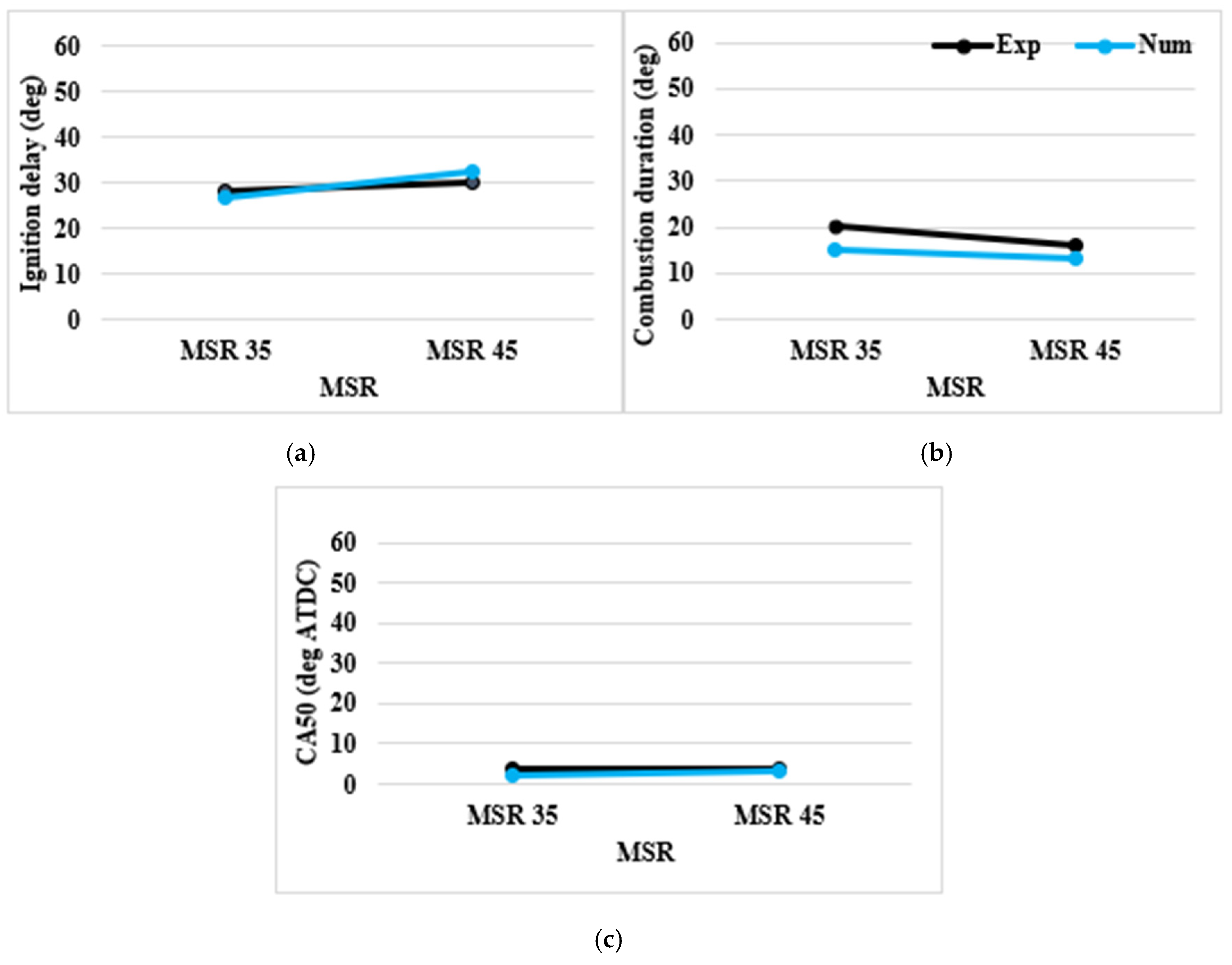
As shown in Figure 6, the comparison between experimental and numerical results indicates that the model accurately captures combustion behavior across different MSRs. Ignition delay increases slightly with MSR due to methanol’s high octane number, which delays auto-ignition. In contrast, combustion duration decreases with increasing MSR, mainly due to the higher laminar flame speed of methanol, further enhanced by its oxygen content and the presence of hydroxyl (-OH) groups in its molecular structure. The numerical results slightly underestimate combustion duration but capture the overall trend. Despite these variations, CA50 remains unchanged. Overall, the model demonstrates good agreement with experimental data, confirming its predictive capability.
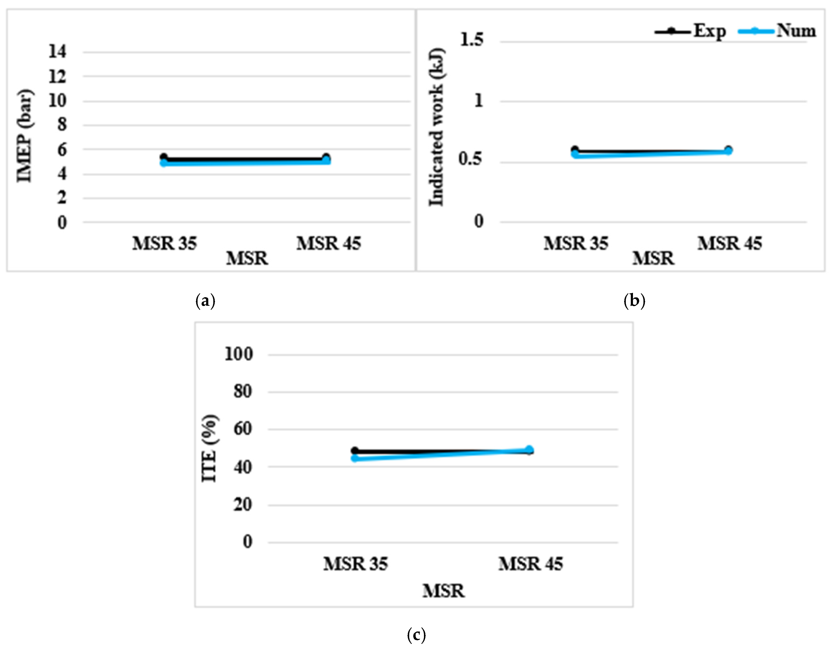
Figure 7 illustrates the comparison between experimental and numerical results in terms of IMEP, indicated work, and indicated thermal efficiency (ITE) for the MSR 35 and MSR 45 cases. The experimental IMEP was kept constant at 5.2 bar across both MSRs as the controlled load parameter, while the numerical model predicts slightly lower values, suggesting that certain in-cylinder phenomena are not fully captured, likely due to simplifications in the combustion sub-model or heat transfer boundary conditions. Despite this marginal discrepancy, the predicted ITE follows the experimental trend closely, remaining in the range of 47.2–48.8%. Overall, the good agreement across all three performance indicators confirms the model’s validity in capturing the principal thermodynamic trends associated with MSR variation.
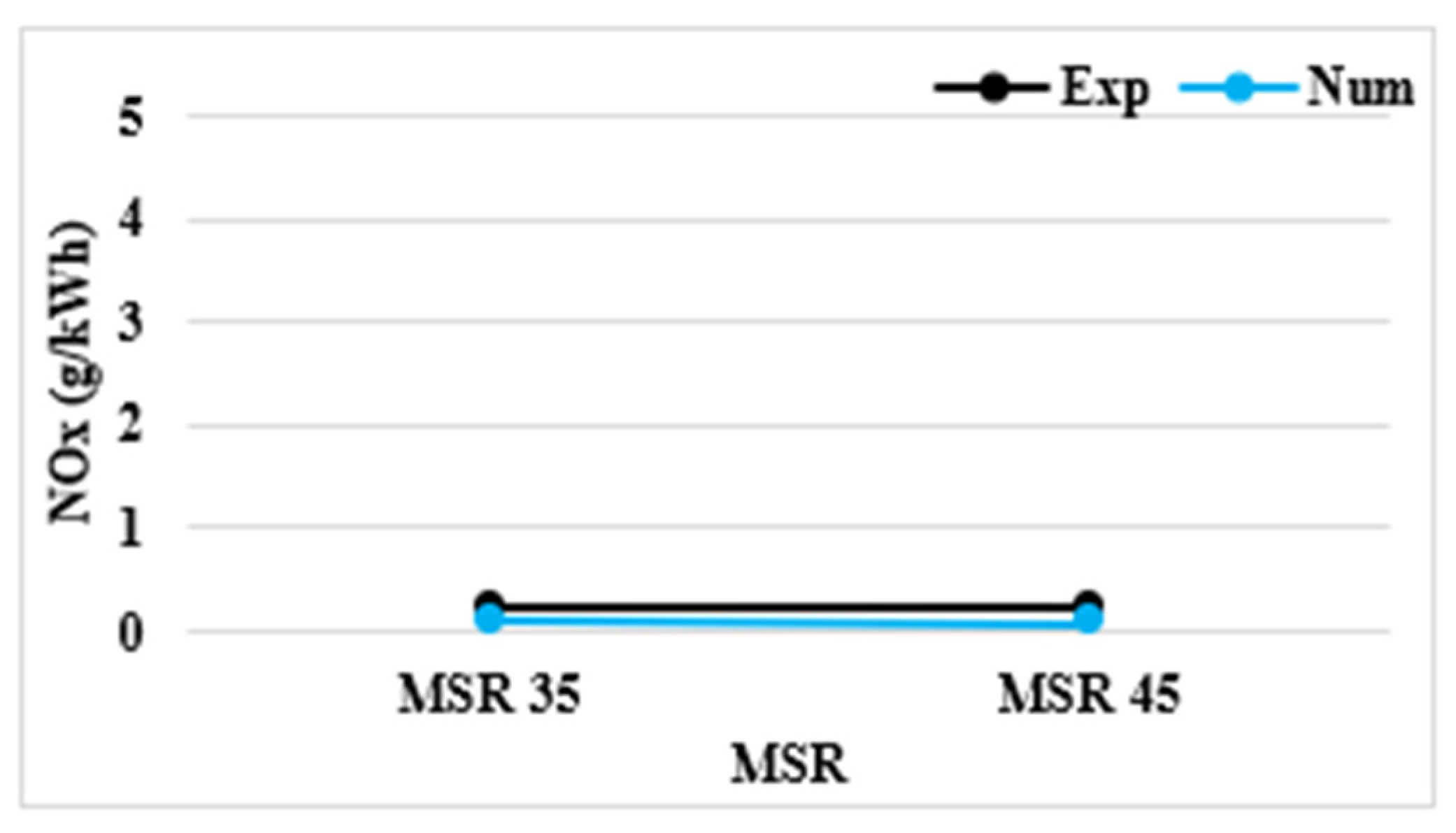
Figure 8 presents the comparison between experimental and numerical NOx emissions for MSR 35 and MSR 45. NOx levels remain very low, below 0.3 g/kWh, and practically unchanged across both conditions. The numerical model slightly underpredicts NOx at both MSRs, a discrepancy attributable to local underestimation of peak in-cylinder temperatures, which consequently reduces the predicted NOx formation rate given the highly non-linear temperature dependence of the Zeldovich mechanism. Nevertheless, the model correctly reproduces the flat trend across MSRs, confirming its validity in capturing the qualitative emission behavior while indicating that further refinement of the combustion temperature sub-model would improve quantitative prediction accuracy.
Building the validated numerical framework established in [14], in which the model was assessed across four methanol substitution ratios (MSR 20, MSR 35, MSR 45, and MSR 55). The MSR 45 case is selected as the baseline configuration for the present study. Hydrogen enrichment is subsequently introduced parametrically at four energy ratios. The diesel and methanol mass flow rates are held constant across all cases (Table 4), with hydrogen supplementing the baseline fuel blend as an additional energy contributor, so that the total energy input rises with HER. This approach ensures that any changes in combustion characteristics, engine performance, and emissions can be directly attributed to the hydrogen enrichment ratio.

3. Results and Discussion

3.1. Spray Characteristics

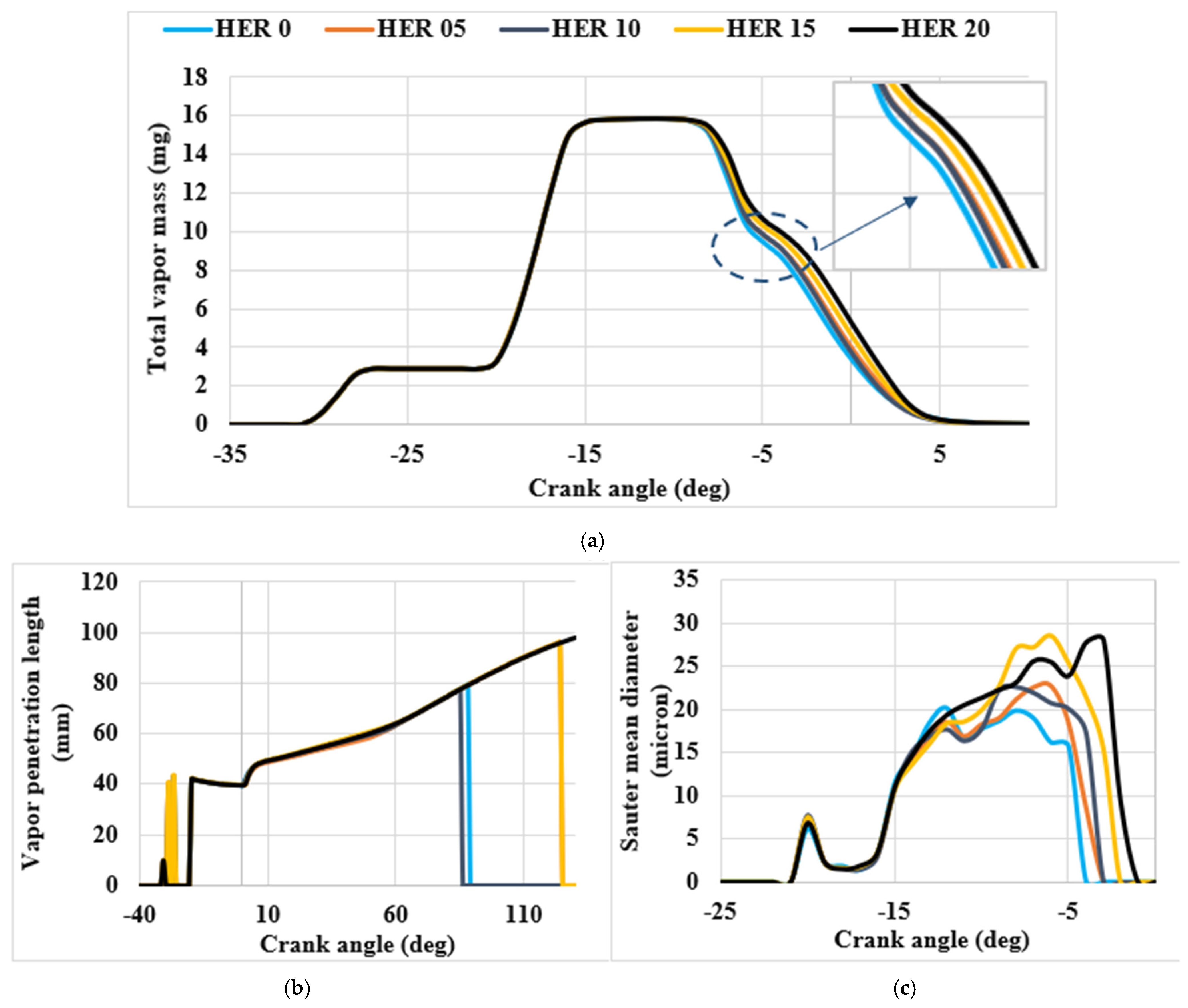
Figure 9a illustrates the total vapor mass of the heptane spray as a function of engine crank angle. As the HER increases (0 HER 20), there is no significant change in the peak total vapor mass. This is explained by the fact that the injected diesel quantity remains constant. At HER 15 and HER 20, a marginal prolongation of late-cycle vapor is observed, indicating a longer combustion duration. The vapor penetration length refers to the distance from the nozzle exit to the point where 99.9% of the injected liquid fuel has vaporized. It is determined by accumulating the mass of fuel vapor in each cell, starting from the nozzle hole. In Figure 9b, the decline in vapor penetration length to zero confirms that the entire diesel has burned. For HER 10, the vaporization process takes less time. As HER increases from HER 10 to HER 15, the peak vapor penetration length increases from 77.6 mm to 95.9 mm. After reaching the peak, the vapor penetration length drops rapidly to zero. Additionally, at HER 15, the peak occurs at a later crank angle compared with HER 10, indicating a longer combustion duration. However, the vapor penetration length continues to increase, reaching approximately 100 mm at HER 20 at 130° CA, with vaporization persisting throughout the entire cycle. This behavior can be explained by the local equivalence ratio fields: as HER increases, the premixed charge becomes progressively fuel-rich, reducing the oxygen mass fraction that drives oxidation-coupled vaporization. As a result, a portion of the diesel remains unburned. Similar observations were recorded by Kokjohn [52] under natural gas/diesel dual-fuel mode and various engine loads. As later explained in Section 3.3, ignition delay shows only a minor variation of approximately 1° CA with hydrogen addition; therefore, the longer vapor penetration observed at higher HER is primarily linked to the extended combustion duration rather than a prolonged ignition delay.
The Sauter mean diameter (SMD) represents the droplet size with an equivalent volume-to-surface area ratio as the overall spray. It serves as a key parameter for evaluating spray distribution quality. A smaller SMD improves liquid fuel vaporization, resulting in enhanced and faster mixing. Figure 9c shows that as the HER increases from 5% to 20%, the Sauter mean diameter also tends to increase, rising from 20.2 µm to 28 µm (+38%). The observed trend is consistent with reduced aerodynamic breakup intensity associated with modified gas-phase properties under hydrogen enrichment. This behavior is governed by the reduction in gas-phase density as hydrogen, with its low molecular weight, displaces a portion of the denser charge gas [22]. The Weber number driving KH instability-based primary breakup scales as:
W e   = ρ g Δ u 2 d σ
where ρ g is the gas-phase density, Δ u is the relative velocity between the liquid jet and surrounding gas, d is the droplet diameter, and σ is the liquid surface tension. Since injection pressure and therefore initial jet momentum are held constant across all HER cases, and heptane surface tension is unchanged, the reduction in Weber number is driven entirely by the decrease in ρ g . A lower Weber number reduces the aerodynamic drag force, destabilizing the liquid jet surface, weakening KH primary breakup, and producing larger primary droplets. The RT secondary breakup mechanism is similarly weakened by reduced gas-phase density, reinforcing the SMD increase. Additionally, hydrogen addition modifies the kinematic viscosity of the charge gas mixture: although hydrogen’s dynamic viscosity is lower than that of air, the substantial reduction in mixture density results in a net increase in kinematic viscosity, which further dampens the aerodynamic instabilities governing droplet disintegration and contributes to the observed SMD increase. As a result, higher HER cases produce sprays with larger droplets, reduced surface-to-volume ratios, slower evaporation mass transfer, and delayed atomization. The in-cylinder gas-phase environment governs the vaporization of diesel droplets. Although the injected diesel quantity remains constant, the addition of hydrogen alters the in-cylinder ambient conditions. The resulting decrease in oxygen mass fraction and changes in gas-phase density reduce the efficiency of droplet breakup and vaporization.

3.2. Flame Propagation Pattern

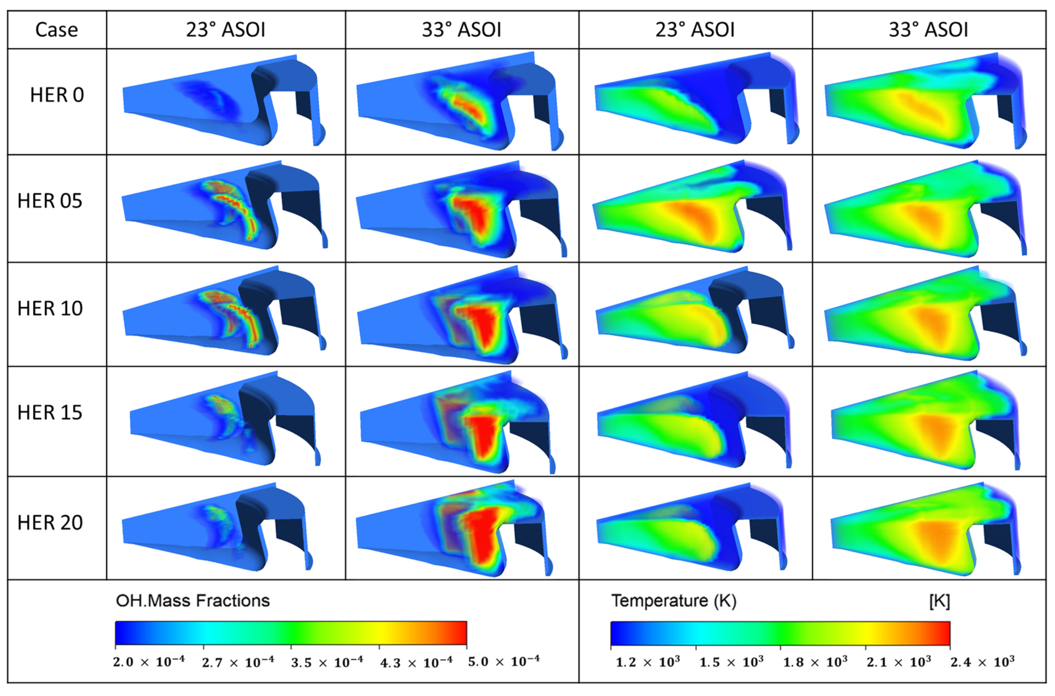
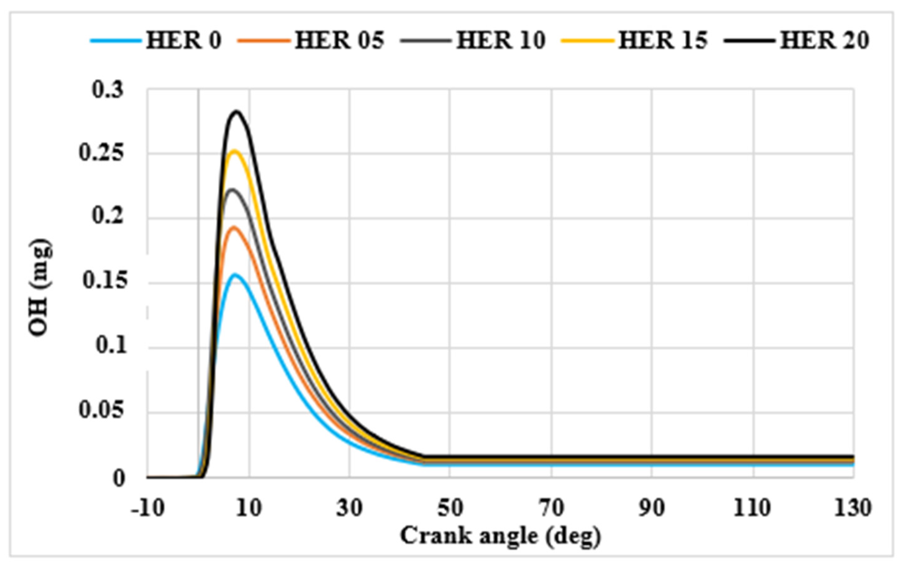
As shown in Figure 10 and Figure 11, OH and temperature spatial contours, and OH radical mass evolution reveal the progressive effect of hydrogen enrichment on combustion structure at 23° and 33° ASOI. The OH radical serves as a reliable indicator of heat-releasing reaction zones. Its peak in-cylinder mass increases monotonically from 0.156 mg at HER 0 to 0.193 mg, 0.222 mg, 0.250 mg, and 0.277 mg at HER 05, 10, 15, and 20, respectively. Spatially, OH mass fractions expand across a greater fraction of the bowl volume with increasing HER, confirming a broader and more volumetrically distributed reaction zone. This is attributed to hydrogen’s high diffusivity, which enhances mixture transport and promotes flame propagation over a wider region of the combustion chamber. Ignition consistently initiates at the spray plume periphery across all HER levels, where the local equivalence ratio approaches stoichiometry under diesel-controlled ignition. At 23° ASOI, OH mass fractions first appear in the 2.0 × 10⁻⁴–2.7 × 10⁻⁴ range before intensifying to 3.5 × 10⁻⁴–5.0 × 10−4 by 33° ASOI. The OH mass peak also shifts slightly toward TDC with increasing HER, consistent with the higher laminar flame speed of hydrogen-enriched mixtures. Temperature contours support these findings. At HER 0, peak temperatures reach approximately 2300 K but are confined to narrow spray-adjacent zones, with hot regions above 2100 K occupying a limited fraction of the bowl. At HER 20, temperatures of 2100–2400 K expand across significantly larger bowl volumes, driven by the combined effect of higher heat release rate, faster flame propagation, and high diffusivity of hydrogen.
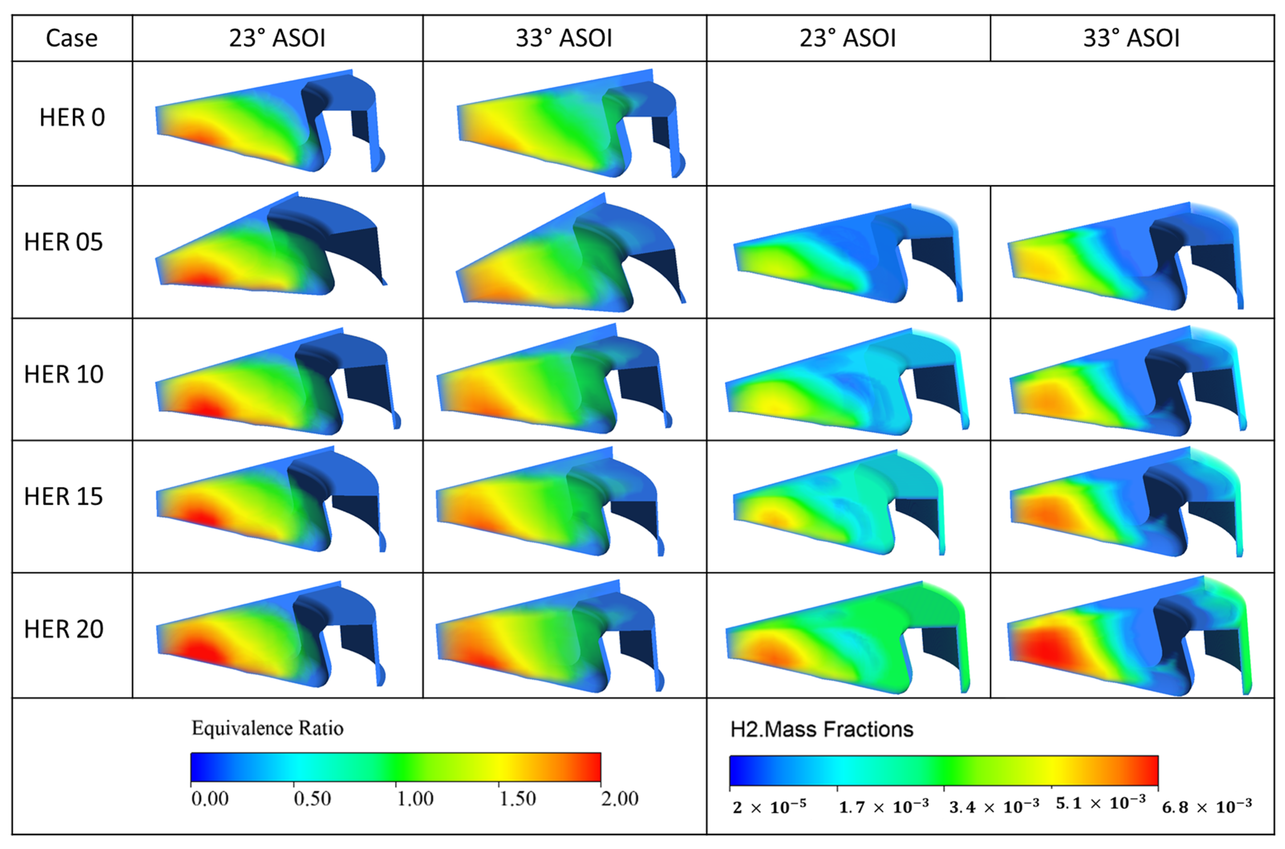
Figure 12 depicts the local equivalence ratio and H2 mass fraction contours for different HERs at various crank angles. At 23° ASOI, equivalence ratios of 1.5–2.0 and H2 mass fractions of 5.1 × 10⁻³–6.8 × 10⁻³ dominate the near-spray region, while the peripheral side exhibits lower values of 2.0 × 10⁻⁵–3.4 × 10⁻³, indicating a leaner premixed hydrogen–methanol charge already partially consumed at the periphery. By 33° ASOI, the periphery transitions entirely to equivalence ratios below 1.0 and H2 mass fractions near 2.0 × 10⁻⁵, confirming complete premixed burnout in the outer regions, whereas the spray core retains H2 mass fractions of 5.1 × 10⁻³–6.8 × 10⁻³ and equivalence ratios above 1.5, reflecting ongoing diffusion-limited combustion under locally oxygen-deficient conditions. This outside-in consumption pattern quantitatively confirms a sequential dual-mode mechanism (premixed peripheral combustion occurring first, followed by diffusion-limited spray core combustion) whose phasing becomes more pronounced at higher HERs.

3.3. In-Cylinder Combustion Pattern

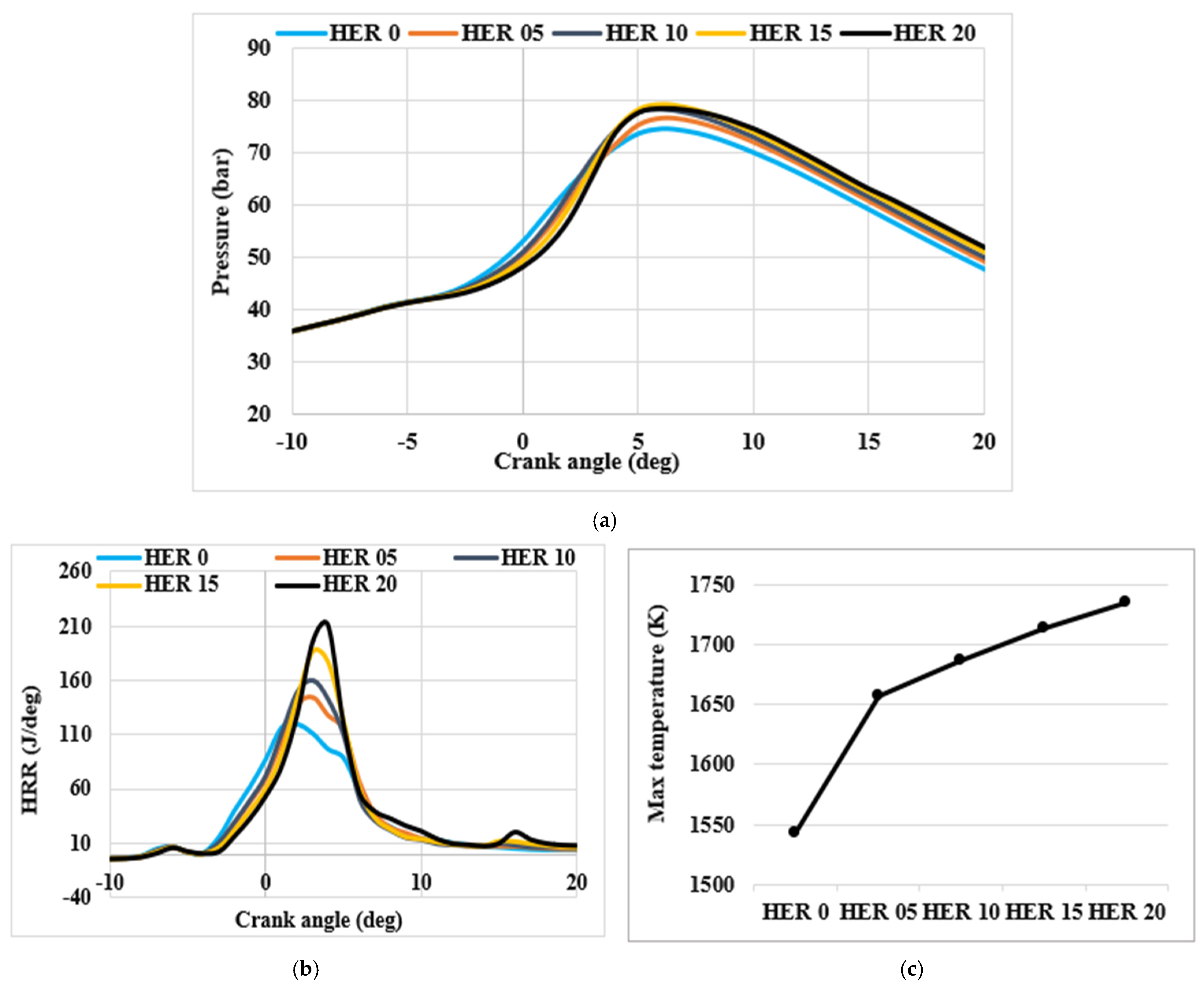
The effect of varying hydrogen enrichment on in-cylinder pressure, heat release rate (HRR), and maximum in-cylinder temperature is illustrated in Figure 13. Peak in-cylinder pressure increases from 75.2 bar at HER 0 to 79.1 bar at HER 20, representing a 5.2% increase, while HRR rises from 129 J/deg to 211 J/deg (+63.6%). Maximum in-cylinder temperature increases from 1542 K at HER 0 to 1735 K at HER 20. These trends follow a clear causal chain: hydrogen’s higher LHV (approximately three times that of diesel and six times that of methanol) increases the total energy input per cycle, which amplifies heat release and raises peak pressures and temperatures. Hydrogen’s high adiabatic flame temperature and flame speed further reinforce this thermal intensification [38,52]. Similar trends have been reported in the literature: Karagöz et al. [31] observed a 7.81% increase in peak in-cylinder pressure with 22% hydrogen addition and a 36.20% increase with 53% hydrogen enrichment compared with neat diesel operation, alongside a proportional increase in peak HRR from 27.99 J/deg to 35.20 J/deg with 22% hydrogen addition. These trends are consistent with the 5.2% pressure increase and 63.6% HRR rise observed in the present study, confirming that hydrogen enrichment systematically amplifies combustion intensity across different dual-fuel engine configurations.
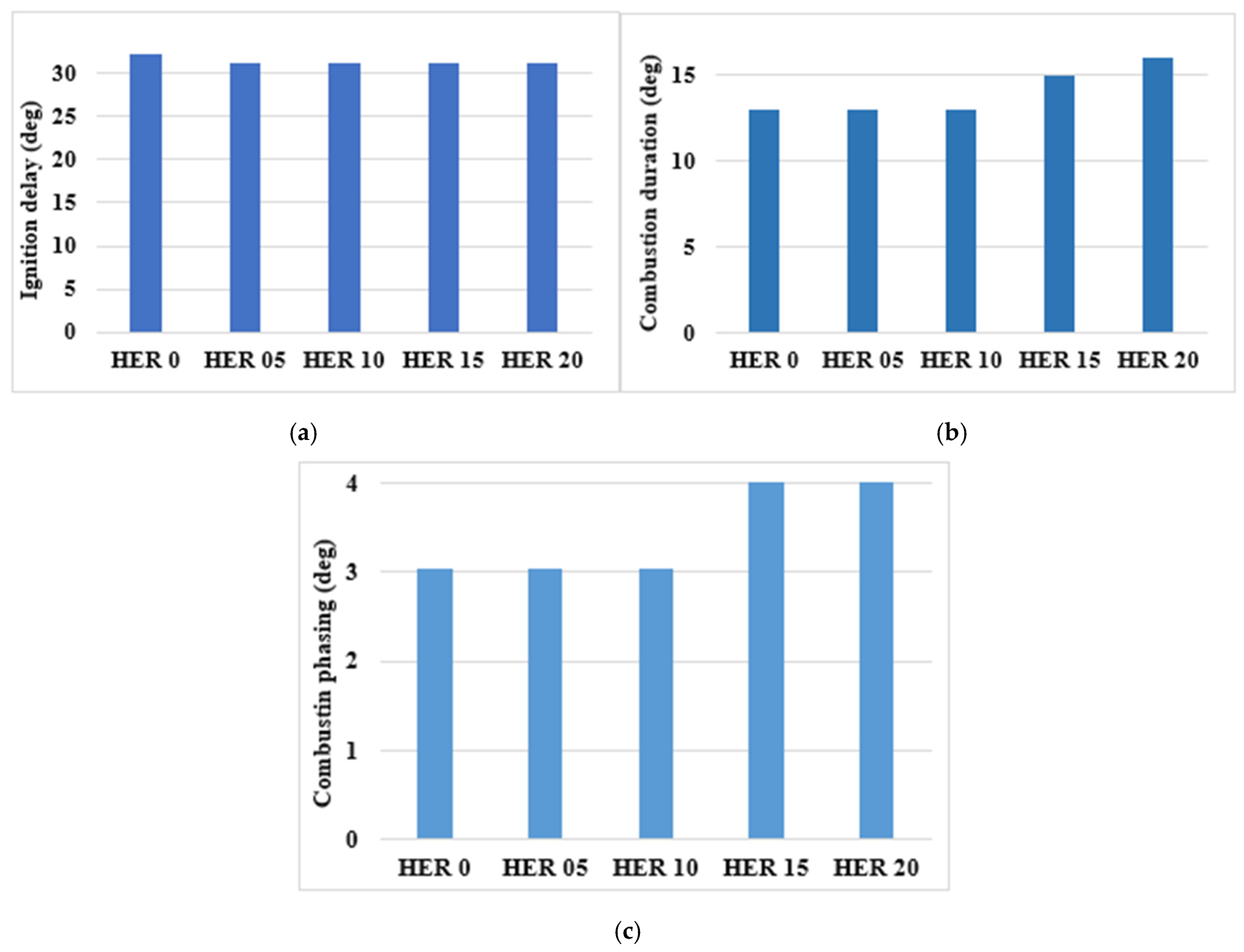
The ignition delay denotes the time between the start of injection and the start of ignition. It is defined as the moment when 10% of the fuel mass has burned. Figure 14a illustrates the effect of HER on ignition delay, showing that the addition of hydrogen has a minor effect on the ignition delay, reducing it by only 1° for HER 05, HER 10, HER 15, and HER 20 compared with HER 0. This near-constancy reflects the dominant role of the diesel pilot, which undergoes auto-ignition in the hot compressed charge within a local spray zone where conditions are predominantly governed by the diesel low-temperature chemistry. Hydrogen, being premixed homogeneously with the intake charge, does not participate in this local auto-ignition chemistry, and its high reactivity and flame speed become relevant only after the pilot ignition event, influencing subsequent flame propagation rather than the ignition delay onset itself. This decoupling physically accounts for the observed insensitivity of ignition delay to HER, consistent with dual-fuel ignition behavior reported by Zou et al. [53]. It also confirms that hydrogen enrichment does not compromise combustion stability or require recalibration of injection timing across all investigated HERs.
Figure 14b shows that for 0 HER 10, the combustion duration remains relatively unchanged. However, for 15 HER 20, the combustion duration increases by approximately 2° CA and 3° CA, respectively, indicating a notable effect of hydrogen addition at higher ratios. The observed increase in combustion duration is primarily attributed to locally fuel-rich pockets that develop in the spray core as HER increases, where the equivalence ratio moves toward richer conditions (Section 3.2), and reduced oxygen mass fraction (decreases due to displacement in the premixed intake composition) slows flame propagation. Although hydrogen’s high mass diffusivity enhances fuel–air mixing and typically promotes faster combustion, this effect is outweighed at the investigated HER levels by the dominant influence of mixture richness. As shown in Section 3.1, higher HER levels additionally produce larger spray droplets and longer vapor penetration, both of which further contribute to a more distributed, longer-duration combustion process. From an engineering perspective, the moderate increase in combustion duration at high HER levels remains acceptable, as it reflects a more complete energy release from the enriched charge rather than incomplete combustion, which is consistent with the higher ITE values observed at elevated HER levels.
The CA50 is the crank angle at which 50% of the mass fraction is burned, representing the center point of heat release. It is commonly used to optimize the combustion process, aiming to reduce fuel consumption and enhance engine performance [54]. Figure 14c indicates that CA50 remains constant for 0 HER   10 . However, it increases for 15 HER   2 0, indicating a shift of approximately 1° CA in combustion phasing as the hydrogen enrichment ratio rises. This is due to the extended combustion duration within this range of HER. From an engineering standpoint, this moderate CA50 shift indicates that combustion phasing remains well controlled across all investigated HER levels. This suggests that hydrogen enrichment up to HER 20 can be implemented without requiring significant recalibration of the injection strategy, which is a practically favorable characteristic for real engine applications.

3.4. Engine Performance and Emissions

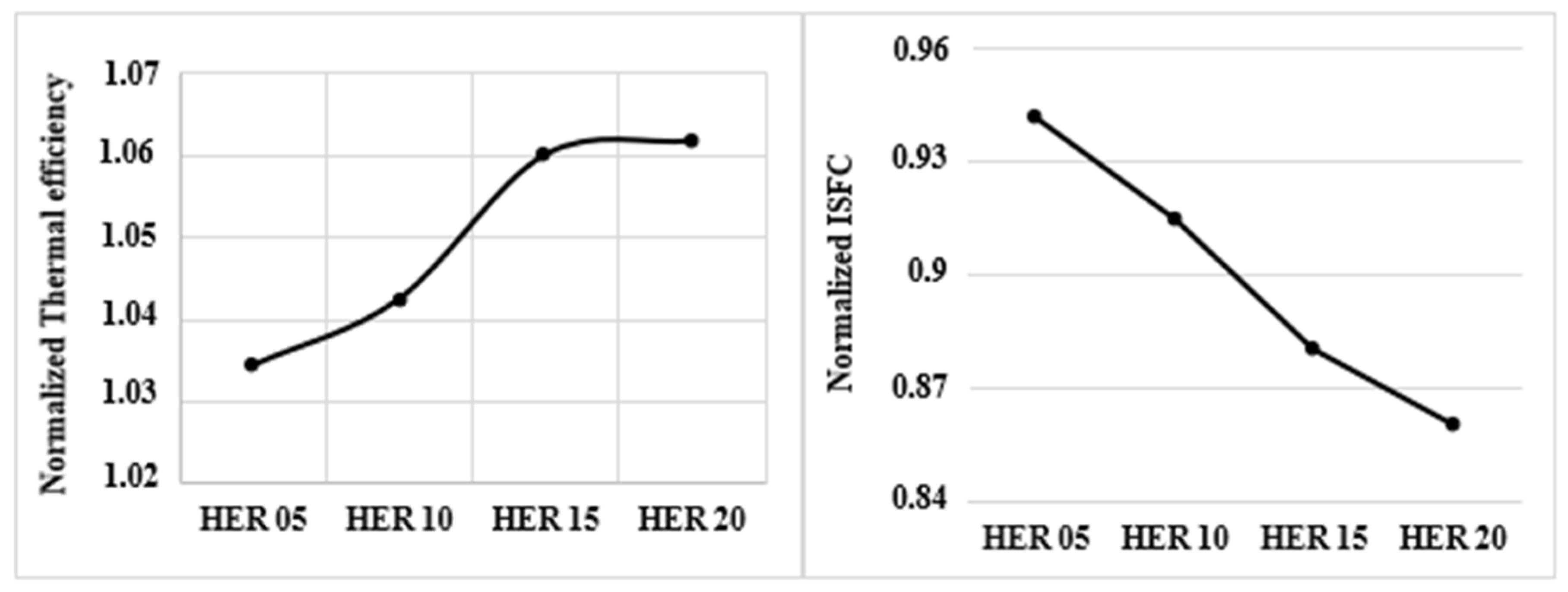
Figure 15 presents the normalized indicated thermal efficiency and indicated specific fuel consumption (ISFC) relative to the baseline methanol–diesel case (HER 0). It should be emphasized that the efficiency results reported in this section refer specifically to engine-level indicated thermal efficiency under the investigated CFD operating conditions, and do not represent a full process-level, or lifecycle energy-efficiency assessment. All performance and CO2 emissions parameters are presented in normalized form with respect to the baseline diesel–methanol dual-fuel without hydrogen enrichment (HER 0). The normalized value of each parameter is obtained by dividing its value at a given HER level by the corresponding value at HER 0, such that a normalized value greater than unity indicates an increase relative to the baseline, while a value below unity indicates a reduction. Hydrogen addition improves thermal efficiency while reducing ISFC across all enrichment levels. The ISFC is computed as the ratio of total fuel mass flow rate (diesel + methanol + hydrogen) to indicated power output. It decreases from approximately 0.94 at HER 05 to 0.86 at HER 20. As noted above, since hydrogen is added, the total energy input and IMEP both increase with HER. Therefore, the ISFC reduction reflects two compounding effects: hydrogen’s LHV (≈120 MJ/kg, approximately 2.8× that of diesel and 6× that of methanol) contributes a disproportionately large energy increment per unit mass added, while an actual improvement in fuel conversion efficiency also occurs, as evidenced by the indicated thermal efficiency, which rises from +3.4% at HER 05 to +6.2% at HER 20. The ITE is defined as:
I T E   % =   P i n d i c a t e d m ˙ d i e s e l × L H V d i e s e l + m ˙ m e t h a n o l × L H V m e t h a n o l + m ˙ h y d r o g e n × L H V h y d r o g e n × 100
where P i n d i c a t e d is the indicated power per cycle [J], m ˙ denotes the mass flow rate [kg/s] of each fuel, and LHV is the lower heating value [MJ/kg]. This efficiency gain is attributed to hydrogen’s low Lewis number, which reduces the flame-quenching distance and enables more complete combustion near the cylinder walls, recovering energy that would otherwise be lost as unburned hydrocarbons [55].
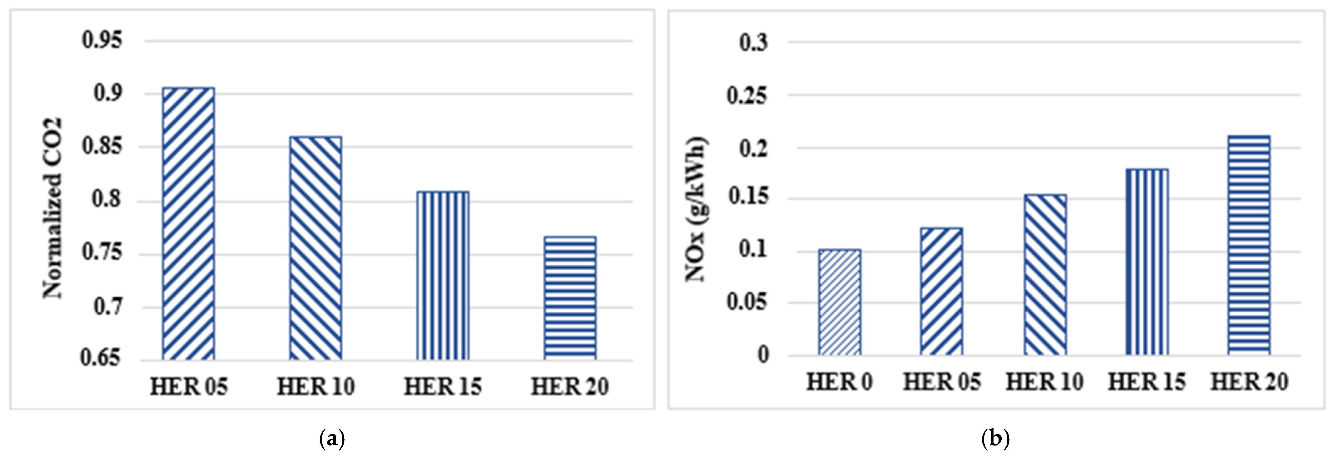
The addition of hydrogen leads to a reduction in CO2 emissions (Figure 16a). Since the carbon-containing fuel inputs (diesel and methanol) are held constant across all HER cases, the total carbon input to the combustion chamber remains unchanged. However, as hydrogen is a carbon-free fuel, its addition increases the total power output without introducing additional CO2, thereby reducing the specific CO2 emissions per unit power output. At HER 05, CO2 emissions decrease by 9.5%, while at higher enrichment ratios, such as HER 20, the reduction reaches 24%. Similar trends were reported by Ene et al. [56], who observed a 6% CO2 reduction with 17% hydrogen substitution in a diesel engine operating at 2000 rpm and 70% load, consistent with the trend observed in the present study, where larger reductions are obtained at higher hydrogen energy ratios.
The effect of hydrogen enrichment on NOx emissions is shown in Figure 16b. NOx emissions increase monotonically with HER, rising from 0.10 g/kWh at HER 0 to 0.21 g/kWh at HER 20. The underlying mechanism follows a clear causal chain. Hydrogen addition increases the total fuel energy input, owing to its wider flammability limits and higher reactivity, thereby promoting more complete heat release. This in turn elevates peak in-cylinder temperatures (Figure 13c), which directly intensifies thermal NOx formation [57,58]. This trend is consistent with findings reported in the literature for hydrogen dual-fuel CI engines, where Karagöz et al. [31] reported an 11.73% increase in NOx with 22% hydrogen addition, rising dramatically to 237.47% at 53% hydrogen enrichment compared with neat diesel. Similarly, Bawne et al. [59] reported a moderate NOx increase from 839 ppm to 936 ppm with hydrogen enrichment, attributed to higher in-cylinder temperatures. Despite representing approximately a twofold increase from HER 0 to HER 20, all absolute NOx values remain at low levels throughout the entire enrichment range.

4. Conclusions

This study examines the impact of hydrogen enrichment ratios on spray atomization and the combustion performance in methanol–diesel dual-fuel engines. The simulations are conducted using an Unsteady Reynolds-Averaged Navier–Stokes approach along with an Eulerian-Lagrangian framework. The G-equation is used to model turbulent flame evolution and establish a direct correlation with the laminar flame speed. The KH-RT model captures spray breakup, while turbulence is governed by the RNG k-ε model. A detailed reaction mechanism of 425 species and 3128 reactions is implemented. The numerical results are validated against experimental data, and the key findings are summarized as follows:
  • Increasing the HER from 5% to 20% raises the SMD of the diesel surrogate spray from 20.2 µm to 28 µm (+38%), indicating a reduction in fuel spray atomization quality. %). This trend is consistent with reduced aerodynamic breakup intensity associated with modified gas-phase properties under hydrogen enrichment. This behavior is governed by the reduction in gas-phase density as hydrogen, with its low molecular weight, displaces a portion of the denser charge gas. This trend is due to the low density of hydrogen, which weakens Weber-number-driven KH aerodynamic breakup, resulting in the formation of larger droplets with reduced surface-to-volume ratios and slower evaporation rates. Despite this spray-side degradation, the combustion-enhancing properties of hydrogen dominate the overall engine response.
  • The peak in-cylinder pressure, HRR, and maximum temperature all increase with the hydrogen enrichment ratio, driven by both higher total energy input and hydrogen’s elevated adiabatic temperature and faster flame speed. The HRR peak amplification of 63.6% at HER 20 indicates enhanced combustion intensity, with the diesel pilot serving primarily as a combustion initiator for the hydrogen–methanol charge.
  • Hydrogen-enriched methanol–diesel mixtures promote combustion efficiency by up to +6.2% at HER 20, with a corresponding ISFC reduction. The gain reflects the proportionally larger increase in indicated power relative to total fuel mass consumption, driven by hydrogen’s high flame speed, high diffusivity, and reduced quenching losses.
  • CO2 decreases by 24% at HER 20 since the carbon-containing fuel inputs (diesel and methanol) are held constant, while hydrogen, being a carbon-free fuel, increases the power output without introducing additional carbon, thereby reducing the CO2 formation per unit power output. NOx increases approximately twofold, rising from 0.10 g/kWh at HER 0 to 0.21 g/kWh at HER 20, driven by the temperature sensitivity of the Zeldovich mechanism and the 193 K elevation in peak cylinder temperature. However, these absolute values remain remarkably low across the entire enrichment range. This confirms that the NOx increase, while consistent, does not represent a critical concern within the operating conditions investigated.
Overall, hydrogen-enriched methanol–diesel dual-fuel combustion represents a pathway toward high-efficiency, low-carbon CI engine operation. From an automotive industry perspective, the numerically demonstrated 6.2% improvement in thermal efficiency and 24% CO2 reduction at HER 20 suggest that meaningful performance and emissions gains may be achievable through fuel strategy adjustments that are largely compatible with existing injection and fuel delivery systems, without requiring major hardware modifications. It should be noted that the reported CO2 reductions reflect direct combustion emissions only and do not account for upstream emissions associated with hydrogen production. Similarly, the reported efficiency improvement refers to engine-level indicated thermal efficiency under the investigated CFD operating conditions and does not represent a full or lifecycle energy-efficiency assessment. However, experimental measurements across a wider range of operating conditions are necessary before drawing definitive conclusions regarding real-world deployment and regulatory compliance. Future work should quantify the coupled effect of EGR rate and injection timing on the NOx-efficiency trade-off, extend the analysis to multi-cycle operation to assess cycle-to-cycle variability, and incorporate a full process analysis, including well-to-wheel energy assessment and life cycle analysis of the hydrogen production pathway, to enable a comprehensive evaluation of this combustion concept as a viable decarbonization strategy.

Author Contributions

Conceptualization, J.J.H., J.R.-F. and M.C.; Methodology, T.H., S.M., J.J.H. and M.C.; Software, T.H. and S.M.; Formal analysis, S.M., J.J.H., J.R.-F. and M.C.; Investigation, T.H.; Writing—original draft, T.H., S.M. and M.C.; Writing—review & editing, T.H., J.J.H. and J.R.-F.; Supervision, J.J.H., J.R.-F. and M.C.; Funding acquisition, M.C. All authors have read and agreed to the published version of the manuscript.

Funding

The experimental data used in this work were obtained under the project PID2022-142004OB-I00, funded by MICIU/AEI/10.13039/501100011033/FEDER and by FEDER/UE, as well as Junta de Comunidades de Castilla-La Mancha through the ETINVI research project (ref: SBPLY/21/180501/000051, also with the participation of the European Regional Development Fund).

Data Availability Statement

The original contributions presented in this study are included in the article. Further inquiries can be directed to the corresponding author.

Conflicts of Interest

The authors declare that they have no known competing financial interests or personal relationships that could have appeared to influence the work reported in this paper.

Nomenclature

Abbreviation/SymbolDefinition
CA50Crank angle at 50% mass fraction burned
CFDComputational Fluid Dynamics
CICompression Ignition
DMCDiscrete Multi-Component vaporization model
EDCEddy Dissipation Concept
EGRExhaust Gas Recirculation
HERHydrogen Enrichment Ratio (energy basis, %)
HRRHeat Release Rate (J/°CA)
ITEIndicated Thermal Efficiency
ISFCIndicated Specific Fuel Consumption
IVCIntake Valve Closing
KH-RTKelvin–Helmholtz/Rayleigh–Taylor model
LHVLower Heating Value
MSRMethanol Substitution Ratio (energy basis, %)
RCCIReactivity Controlled Compression Ignition
RNG k-εRenormalization Group k-epsilon (turbulence model)
SMDSauter mean diameter (µm)
TDCTop Dead Centre
URANSUnsteady Reynolds-Averaged Navier–Stokes
WeWeber number (dimensionless)

References

  1. Aravind, S.; Barik, D.; Pullagura, G.; Chandran, S.S.; Pv, E.; Paramasivam, P.; Balasubramanian, D.; Fouad, Y.; Soudagar, M.E.M.; Kalam, A.; et al. Exposure the role of hydrogen with algae spirogyra biodiesel and fuel-borne additive on a diesel engine: An experimental assessment on dual fuel combustion mode. Case Stud. Therm. Eng. 2025, 65, 105566. [Google Scholar] [CrossRef] [Scilit]
  2. Molima, S.; Hamdi, F.; Hamdi, T.; Muya, G.T.; Mondo, K.; Amsini, S.; Chrigui, M. Effects of H2 substitution on combustion and emissions in ammonia/diesel compression ignition engine. Energy Convers. Manag. 2025, 334, 119858. [Google Scholar] [CrossRef] [Scilit]
  3. Liu, J.; Yang, J.; Sun, P.; Gao, W.; Yang, C.; Fang, J. Compound combustion and pollutant emissions characteristics of a common-rail engine with ethanol homogeneous charge and polyoxymethylene dimethyl ethers injection. Appl. Energy 2019, 239, 1154–1162. [Google Scholar] [CrossRef] [Scilit]
  4. Hamdi, T.; Hamdi, F.; Molima, S.; Chrigui, M. Eulerian-Lagrangian study of swirled combustion in heavy-duty natural gas/diesel dual-fuel engines under low load condition. Combust. Theory Model. 2025, 29, 815–839. [Google Scholar] [CrossRef] [Scilit]
  5. Ajith, B.; Patel, G.M.; Der, O.; Selvan, C.P.; Samuel, O.D.; Annadurai, S.; Thajudeen, K.Y.; Yadav, K.K. Microwave-assisted transesterification of hybrid Garcinia gummi-gutta and Garcinia indica oils: Optimization using RSM and meta-heuristic algorithms for high-yield biodiesel production. Biomass Bioenergy 2025, 202, 108223. [Google Scholar] [CrossRef] [Scilit]
  6. Zhu, C.-Z.; Samuel, O.D.; Patel, G.C.M.; Der, O.; Abbas, M.; Hussain, F.; Ting, T.T. Enhancing CI engine performance and emission control using a hybrid RSM—Rao algorithm for ZnO-doped castor—Neem biodiesel blends. Case Stud. Therm. Eng. 2025, 74, 106841. [Google Scholar] [CrossRef] [Scilit]
  7. Wang, C.; Liu, H.; Zhang, M.; Zhong, X.; Wang, H.; Jin, C.; Yao, M. Experimental and kinetic modeling studies on oxidation of methanol and di-tert-butyl peroxide in a jet-stirred reactor. Combust. Flame 2023, 258, 113093. [Google Scholar] [CrossRef] [Scilit]
  8. Rimkus, A.; Stravinskas, S.; Matijošius, J.; Hunicz, J. Effects of different gas energy shares on combustion and emission characteristics of compression ignition engine fueled with dual-fossil fuel and dual-biofuel. Energy 2024, 312, 133443. [Google Scholar] [CrossRef] [Scilit]
  9. Karvounis, P.; Theotokatos, G.; Patil, C.; Xiang, L.; Ding, Y. Parametric Investigation of Diesel–Methanol Dual-Fuel Marine Engines with Port and Direct Injection. Fuel 2024, 381, 133441. [Google Scholar] [CrossRef] [Scilit]
  10. Verhelst, S.; Turner, J.W.; Sileghem, L.; Vancoillie, J. Methanol as a fuel for internal combustion engines. Prog. Energy Combust. Sci. 2019, 70, 43–88. [Google Scholar] [CrossRef] [Scilit]
  11. Lu, Y.; Wei, M.; Wang, X.; Wu, P.; Zhao, W.; Ji, Q.; Wang, X.; Liu, J. Numerical study of nozzle hole number and pre-injection timing effect on combustion and emissions of methanol/diesel dual-fuel engine. Int. Commun. Heat Mass Transf. 2025, 161, 108512. [Google Scholar] [CrossRef] [Scilit]
  12. Domínguez, V.M.; Hernández, J.J.; Ramos, Á.; Rodríguez-Fernández, J. Role of the Compression Ratio in Dual-Fuel Compression Ignition Combustion with Hydrogen and Methanol. Energy Fuels 2024, 38, 19127–19136. [Google Scholar] [CrossRef] [Scilit]
  13. Vargün, M.; Yılmaz, I.T.; Sayın, C. Investigation of performance, combustion and emission characteristics in a diesel engine fueled with methanol/ethanol/nHeptane/diesel blends. Energy 2022, 257, 124740. [Google Scholar] [CrossRef] [Scilit]
  14. Hamdi, T.; Hamdi, F.; Molima, S.; Hernandez, J.J.; Chrigui, M. Computational Analysis on the Effect of Methanol Energy Ratio on the Spray and Combustion Pattern of a Dual-Fuel Compression Ignition Engine. J. Energy Resour. Technol. Part A Sustain. Renew. Energy 2025, 1, 042303. [Google Scholar] [CrossRef] [Scilit]
  15. Duraisamy, G.; Rangasamy, M.; Govindan, N. A comparative study on methanol/diesel and methanol/PODE dual fuel RCCI combustion in an automotive diesel engine. Renew. Energy 2020, 145, 542–556. [Google Scholar] [CrossRef] [Scilit]
  16. Chen, Z.; He, J.; Chen, H.; Geng, L.; Zhang, P. Comparative study on the combustion and emissions of dual-fuel common rail engines fueled with diesel/methanol, diesel/ethanol, and diesel/n-butanol. Fuel 2021, 304, 121360. [Google Scholar] [CrossRef] [Scilit]
  17. Yin, X.; Yan, Y.; Ren, X.; Yu, L.; Duan, H.; Hu, E.; Zeng, K. Effects of methanol energy substitution ratio and diesel injection timing on a methanol/diesel dual-fuel direct injection engine. Fuel 2025, 382, 133773. [Google Scholar] [CrossRef] [Scilit]
  18. Wang, Q.; Wei, L.; Pan, W.; Yao, C. Investigation of operating range in a methanol fumigated diesel engine. Fuel 2015, 140, 164–170. [Google Scholar] [CrossRef] [Scilit]
  19. Zhang, M.; Cao, J. Comparative study on combustion and emission characteristics of methanol/gasoline blend fueled DISI engine under different stratified lean burn modes. Fuel Process. Technol. 2024, 266, 108160. [Google Scholar] [CrossRef] [Scilit]
  20. Nguyen, D.-K.; Sileghem, L.; Verhelst, S. Exploring the potential of reformed-exhaust gas recirculation (R-EGR) for increased efficiency of methanol fueled SI engines. Fuel 2019, 236, 778–791. [Google Scholar] [CrossRef] [Scilit]
  21. Domínguez, V.M.; Hernández, J.J.; Ramos, Á.; Reyes, M.; Rodríguez-Fernández, J. Hydrogen or hydrogen-derived methanol for dual-fuel compression-ignition combustion: An engine perspective. Fuel 2023, 333, 126301. [Google Scholar] [CrossRef] [Scilit]
  22. Hamdi, T.; Hamdi, F.; Molima, S.; Domínguez, V.M.; Rodríguez-Fernández, J.; Hernández, J.J.; Chrigui, M. Numerical Investigation of Hydrogen Substitution Ratio Effects on Spray Characteristics, Combustion Behavior, and Emissions in a Dual-Fuel Compression Ignition Engine. Machines 2025, 13, 880. [Google Scholar] [CrossRef] [Scilit]
  23. Collodi, G. Hydrogen production via steam reforming with CO2 capture. Chem. Eng. Trans. 2010, 19, 37–42. [Google Scholar] [CrossRef] [Scilit]
  24. Santhanam, K.S.V.; Press, R.J.; Miri, M.J.; Bailey, A.V.; Takacs, G.A. Introduction to Hydrogen Technology; John Wiley & Sons: Hoboken, NJ, USA, 2017. [Google Scholar]
  25. IEA Hydrogen. Global Trends and Outlook for Hydrogen. 2017. Available online: https://www.ieahydrogen.org/wpfd_file/2017_report_global-trends-and-outlook-for-hydrogen_h2tcp/ (accessed on 14 May 2026).
  26. Tang, Y.; Long, W.; Xiao, G.; Wang, Y.; Wang, Y.; Dong, P.; Tian, H.; Zhang, H. Multi-objective optimization of a diesel-methanol dual-direct injection engine integrated with on-board methanol reforming based on RSM-MOPSO coupled algorithm. Int. J. Hydrogen Energy 2025, 156, 150432. [Google Scholar] [CrossRef] [Scilit]
  27. Cardozo, S.D.; Rodríguez-Fernández, J.; Gómez-Doménech, D.; de Almeida Roque, L.F.; Hernández, J.J. Thermodynamic assessment of on-board steam reforming of light alcohols for cleaner CI engines. Case Stud. Therm. Eng. 2025, 74, 106828. [Google Scholar] [CrossRef] [Scilit]
  28. Zhu, Y.; He, Z.; Xuan, T.; Huang, Y.; Zhong, W. Analysis and optimization of energy conversion for an on-board methanol reforming engine with thermochemical recuperation. Fuel 2024, 378, 132767. [Google Scholar] [CrossRef] [Scilit]
  29. Barik, D.; Bora, B.J.; Sharma, P.; Medhi, B.J.; Balasubramanian, D.; Krupakaran, R.L.; Ramegowda, R.; Kavalli, K.; Js, F.J.; Vikneswaran, M.; et al. Exploration of the dual fuel combustion mode on a direct injection diesel engine powered with hydrogen as gaseous fuel in port injection and diesel-diethyl ether blend as liquid fuel. Int. J. Hydrogen Energy 2024, 52, 827–840. [Google Scholar] [CrossRef] [Scilit]
  30. Dong, C.; Zhou, Q.; Zhang, X.; Zhao, Q.; Xu, T.; Hui, S. Experimental study on the laminar flame speed of hydrogen/natural gas/air mixtures. Front. Chem. Eng. China 2010, 4, 417–422. [Google Scholar] [CrossRef] [Scilit]
  31. Karagöz, Y.; Güler, I.; Sandalcı, T.; Yüksek, L.; Dalkılıç, A.S. Effect of hydrogen enrichment on combustion characteristics, emissions and performance of a diesel engine. Int. J. Hydrogen Energy 2016, 41, 656–665. [Google Scholar] [CrossRef] [Scilit]
  32. Barrios, C.C.; Domínguez-Sáez, A.; Hormigo, D. Influence of hydrogen addition on combustion characteristics and particle number and size distribution emissions of a TDI diesel engine. Fuel 2017, 199, 162–168. [Google Scholar] [CrossRef] [Scilit]
  33. Dimitriou, P.; Kumar, M.; Tsujimura, T.; Suzuki, Y. Combustion and emission characteristics of a hydrogen-diesel dual-fuel engine. Int. J. Hydrogen Energy 2018, 43, 13605–13617. [Google Scholar] [CrossRef] [Scilit]
  34. Yahyaei, S.M.J.; Gharehghani, A.; Andwari, A.M. Comprehensive numerical investigation of biodiesel/natural gas dual-fuel compression ignition engine with hydrogen and oxygen enrichment. Int. J. Hydrogen Energy 2025, 98, 254–265. [Google Scholar] [CrossRef] [Scilit]
  35. Bayramoğlu, K.; Bayramoğlu, T.; Polat, F.; Sarıdemir, S.; Alçelik, N.; Ağbulut, Ü. Energy, exergy, and emission (3E) analysis of hydrogen-enriched waste biodiesel-diesel fuel blends on an indirect injection dual-fuel CI engine. Energy 2025, 314, 134124. [Google Scholar] [CrossRef] [Scilit]
  36. Fakhari, A.H.; Gharehghani, A.; Salahi, M.M.; Andwari, A.M. Numerical investigation of the hydrogen-enriched ammonia-diesel RCCI combustion engine. Fuel 2024, 375, 132579. [Google Scholar] [CrossRef] [Scilit]
  37. Ahmadi, R.; Hosseini, S.M. Numerical investigation on adding/substituting hydrogen in the CDC and RCCI combustion in a heavy duty engine. Appl. Energy 2018, 213, 450–468. [Google Scholar] [CrossRef] [Scilit]
  38. Domínguez, V.M.; Hernández, J.J.; Ramos, Á.; Giménez, B.; Rodríguez-Fernández, J. Exploring the effect of methanol and ethanol on the overall performance and substitution window of a dual-fuel compression-ignition engine fueled with HVO. Fuel 2024, 359, 130529. [Google Scholar] [CrossRef] [Scilit]
  39. Patiño-Camino, R.; Cova-Bonillo, A.; Villanueva, F.; Ramos, Á.; Domínguez, V.M.; Rodríguez-Fernández, J.; Hernández, J.J. Impact of short-chain alcohols on carbonyl emissions in dual-fuel compression ignition engines. Fuel 2025, 392, 134916. [Google Scholar] [CrossRef] [Scilit]
  40. Zhang, B.; Wang, H.; Wang, S. Computational Investigation of Combustion, Performance, and Emissions of a Diesel-Hydrogen Dual-Fuel Engine. Sustainability 2023, 15, 3610. [Google Scholar] [CrossRef] [Scilit]
  41. Han, Z.; Reitz, R.D. Turbulence Modeling of Internal Combustion Engines Using RNG κ-ε Models. Combust. Sci. Technol. 1995, 106, 267–295. [Google Scholar] [CrossRef] [Scilit]
  42. Tan, Z.; Reitz, R. Modeling Ignition and Combustion in Spark-Ignition Engines Using a Level Set Method; SAE Technical Paper 2003-01-0722; SAE International: Warrendale, PA, USA, 2003; Volume 1. [Google Scholar] [CrossRef] [Scilit]
  43. Peters, N. Turbulent Combustion. In Cambridge Monographs on Mechanics; Cambridge University Press: Cambridge, UK, 2000. [Google Scholar] [CrossRef] [Scilit]
  44. Liang, L.; Reitz, R.D. Spark Ignition Engine Combustion Modeling Using a Level Set Method with Detailed Chemistry; SAE International: Warrendale, PA, USA, 2006; Available online: https://api.semanticscholar.org/CorpusID:101376765 (accessed on 14 May 2026).
  45. Gülder, Ö.L. Correlations of Laminar Combustion Data for Alternative S.I. Engine Fuels; SAE Technical Paper; SAE International: Warrendale, PA, USA, 1984; p. 26. [Google Scholar] [CrossRef] [Scilit]
  46. Verma, I.; Bish, E.; Kuntz, M.; Meeks, E.; Puduppakkam, K.; Naik, C.; Liang, L. CFD Modeling of Spark Ignited Gasoline Engines—Part 1: Modeling the Engine Under Motored and Premixed-Charge Combustion Mode; SAE Technical Paper; SAE International: Warrendale, PA, USA, 2016; p. 7. [Google Scholar] [CrossRef] [Scilit]
  47. Kong, S.-C.; Reitz, R.D. Use of Detailed Chemical Kinetics to Study HCCI Engine Combustion with Consideration of Turbulent Mixing Effects. J. Eng. Gas Turbines Power 2002, 124, 702–707. [Google Scholar] [CrossRef] [Scilit]
  48. Kong, D.; Eckhoff, R.K.; Alfert, F. Auto-ignition of CH4 air, C3H8 air, CH4/C3H8/air and CH4/CO2/air using a 11 ignition bomb. J. Hazard. Mater. 1995, 40, 69–84. [Google Scholar] [CrossRef] [Scilit]
  49. Puduppakkam, K.V.; Liang, L.; Naik, C.V.; Meeks, E.; Kokjohn, S.L.; Reitz, R.D. Use of Detailed Kinetics and Advanced Chemistry-Solution Techniques in CFD to Investigate Dual-Fuel Engine Concepts. SAE Int. J. Engines 2011, 4, 1127–1149. [Google Scholar] [CrossRef] [Scilit]
  50. Beale, J.C.; Reitz, R.D. Modeling spray atomization with the Kelvin-Helmholtz/Rayleigh-Taylor hybrid model. At. Sprays 1999, 9, 623–650. [Google Scholar] [CrossRef] [Scilit]
  51. Ra, Y.; Reitz, R.D. A vaporization model for discrete multi-component fuel sprays. Int. J. Multiph. Flow 2009, 35, 101–117. [Google Scholar] [CrossRef] [Scilit]
  52. Kokjohn, S.L. Reactivity Controlled Compression Ignition (RCCI) Combustion. Doctoral Dissertation, University of Wisconsin-Madison, Madison, WI, USA, 2012. Available online: https://search.library.wisc.edu/digital/AHLTSXGLPFKZFU8Z (accessed on 14 May 2026).
  53. Zou, H.; Wang, L.; Liu, S.; Li, Y. Ignition delay of dual fuel engine operating with methanol ignited by pilot diesel. Front. Energy Power Eng. China 2008, 2, 285–290. [Google Scholar] [CrossRef] [Scilit]
  54. Calam, A. Effects of the fusel oil usage in HCCI engine on combustion, performance and emission. Fuel 2020, 262, 116503. [Google Scholar] [CrossRef] [Scilit]
  55. Duan, X.; Xu, L.; Xu, L.; Jiang, P.; Gan, T.; Liu, H.; Ye, S.; Sun, Z. Performance analysis and comparison of the spark ignition engine fuelled with industrial by-product hydrogen and gasoline. J. Clean. Prod. 2023, 424, 138899. [Google Scholar] [CrossRef] [Scilit]
  56. Ene, A.M.; Pana, C.; Negurescu, N.; Cernat, A.; Fuiorescu, D.; Nutu, C. Effects of the hydrogen addition on combustion in automotive diesel engine. IOP Conf. Ser. Mater. Sci. Eng. 2020, 997, 012115. [Google Scholar] [CrossRef] [Scilit]
  57. Köse, H.; Ciniviz, M. An experimental investigation of effect on diesel engine performance and exhaust emissions of addition at dual fuel mode of hydrogen. Fuel Process. Technol. 2013, 114, 26–34. [Google Scholar] [CrossRef] [Scilit]
  58. Bari, S.; Esmaeil, M.M. Effect of H2/O2 addition in increasing the thermal efficiency of a diesel engine. Fuel 2010, 89, 378–383. [Google Scholar] [CrossRef] [Scilit]
  59. Bawne, S.K.; Patil, V.; Singh, P.; Kumar, S. Thermodynamic investigation of hydrogen-enriched diesel dual-fuel CI engine through first and second law analysis. Int. J. Hydrogen Energy 2026, 227, 154561. [Google Scholar] [CrossRef] [Scilit]
Figure 1. Computational model.
Machines 14 00563 g001
Figure 2. Flowchart of the numerical simulation methodology.
Machines 14 00563 g002
Figure 3. Effect of mesh resolution on cylinder pressure.
Machines 14 00563 g003
Figure 4. Time-step sensitivity.
Machines 14 00563 g004
Figure 5. Model validation: comparison of predicted and measured in-cylinder pressure and heat release rate for MSR 35 and MSR 45.
Machines 14 00563 g005
Figure 6. Effect of MSR on combustion characteristics: (a) ignition delay, (b) combustion duration, and (c) combustion phasing CA50.
Machines 14 00563 g006
Figure 7. Effect of MSR on engine performance: (a) indicated work, (b) ITE, and (c) IMEP.
Machines 14 00563 g007
Figure 8. NOx emissions at different MSRs.
Machines 14 00563 g008
Figure 9. Effect of HER on-spray characteristics: (a) vapor mass, (b) vapor penetration length, and (c) Sauter mean diameter, for different HER values.
Machines 14 00563 g009
Figure 10. Spatial contours of OH radical and temperature for various HERs.
Machines 14 00563 g010
Figure 11. OH variation process.
Machines 14 00563 g011
Figure 12. Spatial contours of equivalence ratio and H2 mass fraction for various HERs.
Machines 14 00563 g012
Figure 13. Effect of HER on (a) in-cylinder pressure, (b) heat release rate, and (c) max temperature.
Machines 14 00563 g013
Figure 14. Impact of HER on (a) ignition delay, (b) combustion duration, and (c) combustion phasing CA50.
Machines 14 00563 g014
Figure 15. Effect of HER on ISFC and thermal efficiency.
Machines 14 00563 g015
Figure 16. Effect of HER on (a) CO2 and (b) NOx emissions.
Machines 14 00563 g016
Table 1. Engine specifications.
ParametersValue
Number of cylinders1
Bore × stroke [mm]106.5 × 127
Connecting rod length [mm]203
Displacement volume [L]1.13
Compression ratio [-]15.84
Diesel fuel injection typeDirect injection
Diesel injection systemHigh-pressure CRDI
Diesel injection pressure [bar]600
Methanol injection typePort injection
Methanol injection pressure [bar]5
Hydrogen deliveryPremixed with intake charge
Table 2. Initial and boundary conditions.
Initial and Boundary ConditionsSpecific Conditions
Temperature of the combustion chamber at IVC [K]400
Pressure inside the combustion chamber at IVC [bar]1.3
Turbulent kinetic energy [m2/s2]17
Turbulence length scale [m]0.005
Temperatures of cylinder head, piston, and liner wall [K]400
Table 3. Computational resources.
CaseCoreTimeMemoryCPUFrequency
MSR 35815 h, 25 min, 18.5 s2355 MB43.19 Hz
MSR 45814 h, 22 min, 45.5 s2342 MB43.19 Hz
Table 4. Operating variables for different HERs.
Operating VariablesHER 05HER 10HER 15HER 20
m ˙ a i r [g/s]7.97.97.97.9
m ˙ d i e s e l [g/s]0.210.210.210.21
m ˙ M e t h a n o l [g/s]0.3670.3670.3670.367
m ˙ H y d r o g e n [g/s]0.006870.01370.02060.0276
EGR [%]7.5
Start of diesel pilot injection BTDC [CAD]30303030
End of diesel pilot injection BTDC [CAD]27.927.927.927.9
Start of diesel main injection BTDC [CAD]20202020
End of diesel main injection BTDC [CAD]16161616
Disclaimer/Publisher’s Note: The statements, opinions and data contained in all publications are solely those of the individual author(s) and contributor(s) and not of MDPI and/or the editor(s). MDPI and/or the editor(s) disclaim responsibility for any injury to people or property resulting from any ideas, methods, instructions or products referred to in the content.