Article

MTPA Control Strategy for Brushless DC Motors Based on Zero-Sequence Current Injection

1
School of Electrical Engineering, Yanshan University, No. 438 West Hebei Avenue, Qinhuangdao 066004, China
2
Hebei Key Laboratory of Power Electronics for Energy Conservation and Drive Control, Yanshan University, No. 438 West Hebei Avenue, Qinhuangdao 066004, China
*
Author to whom correspondence should be addressed.
Machines 2026, 14(5), 536; https://doi.org/10.3390/machines14050536
Submission received: 22 March 2026 / Revised: 6 May 2026 / Accepted: 9 May 2026 / Published: 11 May 2026
(This article belongs to the Section Electrical Machines and Drives)

Abstract

Under ideal trapezoidal back electromotive force (EMF) conditions, a brushless direct current (BLDC) motor can produce constant instantaneous electromagnetic torque when supplied with ideal three-phase square-wave currents. However, this operating mode may result in relatively high copper loss. In practical applications, where both the back-EMF and the current waveforms deviate from their ideal shapes, significant torque ripple is introduced. To address these issues, this paper proposes a maximum torque per ampere (MTPA) control strategy for BLDC motors based on zero-sequence current injection. An improved Park (3s–3r) is employed to develop the mathematical model, in which the synthesized non-zero-sequence components are mapped exclusively onto the q-axis. By properly regulating the d-axis and 0-axis reference currents, the proposed strategy achieves minimum copper loss operation. Based on this framework, a torque control system incorporating zero-sequence current injection is established to further enhance performance. The feasibility and effectiveness of the proposed control strategy are validated through digital signal processing (DSP)-based experimental results.

1. Introduction

1.1. Research Background

BLDC motors (BLDCMs) with trapezoidal back-EMF are widely used in applications requiring low cost, simple control, and high reliability, such as electric vehicles, household appliances, and aerospace actuators [1]. Compared with sinusoidal permanent magnet synchronous motors (PMSMs), BLDCMs are particularly suitable for systems employing square-wave current control due to their simpler inverter implementation and lower computational burden. However, in practical applications, non-ideal trapezoidal back-EMF waveforms and distorted square-wave currents introduce significant torque ripple. When operating in the conventional two-phase conduction mode, BLDCMs typically exhibit severe commutation torque ripple, which may reach up to 50% of the average torque [2]. Therefore, the suppression of commutation torque ripple has long been a key research focus in BLDC motor drive systems [3].

1.2. Literature Review

To address the problem of large torque ripple in BLDCMs, recent studies have explored various approaches, including novel circuit topologies and modified modulation methods. In [4], a hybrid DC–DC converter is added at the front end of the inverter. This circuit boosts the DC bus voltage during commutation, thereby accelerating the rising rate of the incoming phase current, while also reducing the voltage requirement of the DC source. In [5], a capacitor that is pre-charged by the boost device during the non-commutation interval is connected in series with the DC voltage source during commutation, increasing the DC bus voltage to four times the back-EMF and effectively suppressing commutation torque ripple. However, all of these topology-based circuits introduce additional components, which increases circuit size and cost. In [6], a pulse-width modulation model predictive control (PWM-MPC) algorithm is proposed. By predicting the rates of change of the incoming and outgoing phase currents, the algorithm adjusts the duty cycle to maintain the non-commutating phase current. This method does not require any modification to the inverter topology but increases the commutation time at high speeds. In [7], a voltage compensation method based on pulse amplitude modulation is introduced to alleviate torque reduction caused by diode freewheeling during commutation. Compared with the two-phase conduction mode, a BLDC motor operating in three-phase conduction mode does not exhibit commutation torque ripple [8]. Furthermore, when all three phases conduct simultaneously, optimizing the three-phase currents can reduce torque ripple caused by harmonics and decrease motor copper losses, thereby achieving minimum-copper-loss operation [9].
For BLDCMs with trapezoidal back-EMF, the two-phase conduction mode, as the mainstream drive mode, is easy to implement and offers simplicity and reliability. However, compared with the three-phase conduction mode, it results in higher copper losses when delivering the same electromagnetic torque [10]. Excessive copper loss not only reduces the efficiency and energy-saving performance of the BLDC motor but also increases the stator temperature, decreases the heat dissipation capability of the rotor-side core, and raises the risk of overheating and irreversible demagnetization of the permanent magnets. In [11], the three-phase back-EMF is decomposed into the fundamental component as well as the 5th- and 7th-order harmonics. After performing the corresponding coordinate transformations, the d-axis and q-axis back-EMF expressions in each harmonic reference frame are obtained, thereby establishing a mathematical model in multiple reference frames. This approach not only involves a large number of parameters but also requires consideration of torque ripple resulting from torque coupling among different harmonic components of the back-EMF and phase currents. In [12], the conventional coordinate transformation matrix is improved. By setting the d-axis and 0-axis currents to zero, the q-axis current, calculated from the reference electromagnetic torque, is converted back through the inverse coordinate transformation to obtain the three-phase reference currents. However, this method does not achieve minimization of the required stator current. In [13,14], within the synchronous rotating reference frame, real-time back-EMF coefficients on the d-axis and q-axis are utilized to derive the corresponding reference currents for minimum-copper-loss operation using the Lagrange multiplier method. However, these reference currents are time-varying, which makes it difficult to achieve torque decoupling between the d-axis and q-axis. In addition, PI control of time-varying currents may introduce steady-state errors. In [15], based on real-time permanent-magnet flux linkage and back-EMF coefficients, the stator flux linkage reference required for minimum-copper-loss control is calculated, and direct torque control is implemented using both the flux linkage and torque references. However, considering the relatively small proportion of armature-reaction flux linkage in the total stator flux linkage of BLDCMs, direct hysteresis control based on stator flux linkage is unlikely to achieve satisfactory minimum-copper-loss performance.

1.3. Main Innovations and Contributions

This paper proposes an MTPA control strategy for BLDCMs based on zero-sequence current injection. Compared with existing methods for reducing copper loss in BLDCMs, the proposed approach introduces an additional bridge leg to the conventional three-leg inverter, thereby providing a path for zero-sequence current. This enables the zero-sequence current to contribute to torque production, allowing the root mean square (RMS) value of the three-phase currents to be minimized while maintaining the same electromagnetic torque.
The main innovations and contributions of this study are summarized as follows.
(1) Unlike conventional BLDC motor MTPA strategies based on three-leg inverters, this study explicitly exploits the zero-sequence back-EMF component of trapezoidal-back-EMF BLDCMs. By introducing a fourth inverter leg connected to the motor neutral point, a controllable zero-sequence current path is established, allowing the zero-sequence back-EMF to participate in electromagnetic torque production.
(2) A minimum-copper-loss current allocation method is developed in the q–0 reference frame. The torque contributions of both the non-zero-sequence and zero-sequence components are considered, and a further M T ρ transformation is introduced to align the synthesized back-EMF with the torque-producing axis. As a result, the optimal q-axis and zero-sequence current references can be analytically obtained for MTPA operation.
(3) A practical four-leg-inverter-based BLDC motor drive system, including feedforward compensation and a dedicated modulation scheme, is constructed and experimentally validated. Compared with the conventional three-leg strategy, the proposed method reduces the copper-loss-related current index by more than 6% under representative operating conditions while maintaining stable dynamic response.
(4) To further evaluate practical applicability, a system-level efficiency and life-cycle cost analysis is added, demonstrating that the energy-saving benefit can compensate for the additional hardware cost of the fourth bridge leg in medium- and high-duty-cycle applications.

2. Theoretical Justification and Proposed Strategy

This section presents the theoretical justification for the proposed control methodology. First, the limitations of the conventional MTPA control system based on the standard rotating coordinate transformation are analyzed to establish a baseline. Subsequently, the theoretical framework of the novel MTPA control system, which incorporates zero-sequence current injection, is introduced. By integrating a four-leg inverter topology with refined coordinate transformations, mathematical derivations are provided to demonstrate how minimum-copper-loss operation can be fundamentally achieved.

2.1. MTPA Control Based on the Conventional Rotating Coordinate Transformation

Under ideal trapezoidal back-EMF, a BLDC motor can produce constant instantaneous electromagnetic torque when supplied with ideal square-wave currents in the two-phase conduction mode; however, it cannot achieve minimum-copper-loss operation. To maintain constant instantaneous torque while also realizing minimum-copper-loss operation, the three-phase conduction mode should be adopted. For sinusoidal PMSMs, the decoupling between electromagnetic torque and flux linkage in the dq synchronous rotating reference frame, obtained via the standard rotating coordinate transformation, allows the delivery of the required torque while achieving minimum-copper-loss operation. Similarly, for BLDCMs, the rotating coordinate transformation can be employed to simultaneously achieve the required electromagnetic torque and minimum-copper-loss operation.
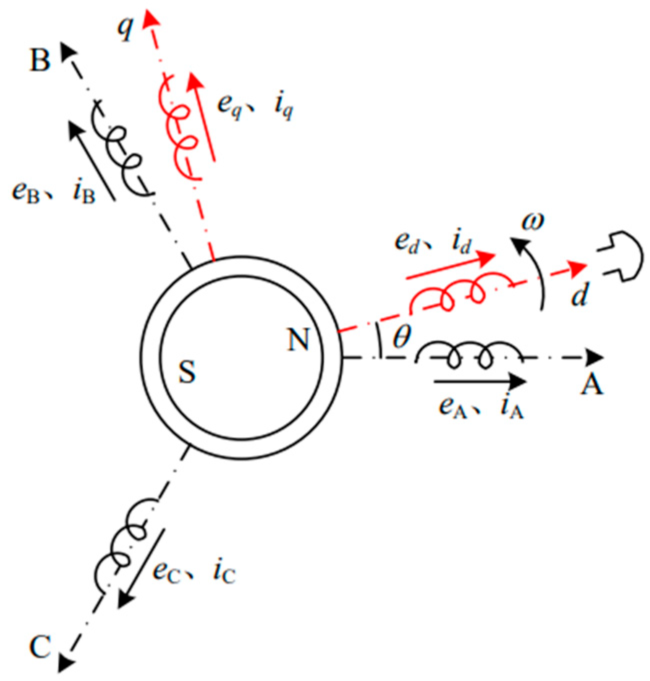
Figure 1 illustrates the schematic relationship between the three-phase stationary reference frame and the two-axis synchronous rotating reference frame of the BLDC motor.
In Figure 1, the direction of the permanent magnet magnetic field is defined as the d-axis, and θ denotes the position angle of the permanent magnet magnetic field relative to the phase-A winding at the current instant; this angle also corresponds to the rotor position at that instant. The q-axis is defined as the direction leading the d-axis by 90 electrical degrees in space. Both axes rotate counterclockwise at the synchronous speed, which corresponds to the rotor speed ω .
Based on the conventional coordinate transformation commonly employed in permanent-magnet synchronous motor control, the back-EMF can be synthesized; that is, the non-zero-sequence components of the phases A, B, and C back-EMFs are equivalently combined. The conventional coordinate transformation matrix, with the rotor position used as the rotation angle, is expressed as follows:
C = 2 3 cos θ sin θ sin θ cos θ 1 1 2 1 2 0 3 2 3 2
To facilitate the computation of the inverse coordinate transformation matrix, this paper employs a power-invariant transformation matrix. By transforming the back-EMFs of phases A, B, and C into the d-axis and q-axis components, the corresponding d-axis and q-axis back-EMFs are obtained:
e d e q = 2 3 cos θ cos θ 2 3 π cos θ + 2 3 π sin θ sin θ 2 3 π sin θ + 2 3 π 1 2 1 2 1 2 · e A e B e C
where e A , e B , e C denote the phase back-EMFs of phases A, B, and C, respectively, and e d , e q denote the back-EMFs in the d-axis and q-axis, respectively.
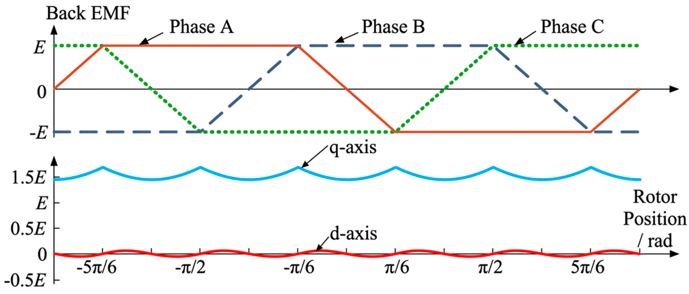
Figure 2 shows the ideal back-EMF waveforms in the three-phase stationary reference frame, as well as the corresponding waveforms in the two-axis synchronous rotating reference frame obtained by substituting them into (2).
In Figure 2, E denotes the peak value of the ideal back-EMF in the three-phase stationary reference frame. As shown in Figure 2, after applying the conventional rotating coordinate transformation, the d-axis and q-axis back-EMFs exhibit periodic fluctuations.
The instantaneous electromagnetic torque in the dq rotating reference frame can be expressed as follows
T e = 1 Ω ( e d i d + e q i q )
where T e is the electromagnetic torque; e d and e q are the d-axis and q-axis back-EMFs, respectively; i d and i q are the corresponding current components.
As shown in Figure 2 and (2), in the dq synchronous rotating reference frame obtained through the conventional coordinate transformation, e d is a non-zero and time-varying quantity. As a result, the d-axis current i d required for minimum-copper-loss operation is not zero. Therefore, under the conventional coordinate transformation, both the d-axis and q-axis currents contribute to torque production. In other words, torque decoupling between the transformed axes cannot be achieved.
By applying back-EMF orientation, the synthesized back-EMF can be confined exclusively to the q-axis. This enables precise torque control with the d-axis current set to zero, thereby establishing the foundation for minimum-copper-loss operation. In this paper, a non-zero-sequence back-EMF orientation method is proposed. By adjusting the rotation angle in (1) from θ to θ , the modified transformation matrix in (4) is obtained. This adjustment not only preserves the original properties of the conventional transformation but also ensures that the d-axis back-EMF component is eliminated. Specifically, after transforming the phases A, B, and C back-EMFs using the proposed matrix C , enforcing a zero d-axis back-EMF condition leads to the determination of θ in (4). In this way, non-zero-sequence back-EMF orientation is effectively achieved.
C = 2 3 cos θ sin θ sin θ cos θ 1 1 2 1 2 0 3 2 3 2
where θ is defined as
θ = arctan e A 1 2 e B + e C 3 2 e C e B
The q-axis component of the back-EMF is given by
e q = 2 3 e A 2 + e B 2 + e C 2 e A e B e B e C e C e A
As shown from (4), the proposed transformation enables non-zero-sequence back-EMF orientation, in which the back-EMF is entirely concentrated on the q-axis while the conventional structure of the rotating coordinate transformation matrix is preserved. However, although the d-axis back-EMF component can be eliminated, the q-axis back-EMF remains time-varying and cannot be maintained as a constant value. Therefore, it is still impossible to achieve complete torque decoupling under this transformation.

2.2. Proposed MTPA Control Based on Zero-Sequence Current Injection

2.2.1. Theory of the MTPA Control System with Zero-Sequence Current Injection

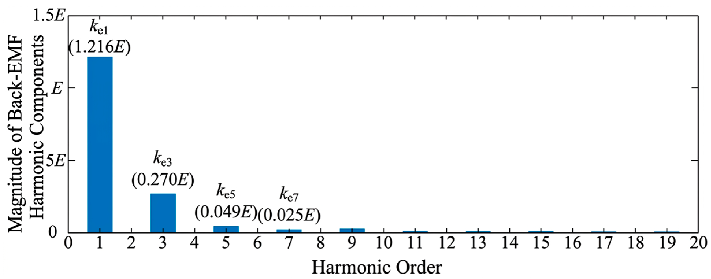
By improving the coordinate transformation and adopting the three-phase conduction mode, lower copper loss than that of the conventional two-phase conduction mode can be achieved using a three-leg inverter. However, this approach has inherent theoretical limitations arising from both the back-EMF characteristics of the BLDC motor and the structural constraints of the three-leg inverter. As shown in Figure 3, Fourier decomposition reveals that the back-EMF of the BLDC motor consists of a fundamental component along with multiple higher-order harmonics. Among these, significant zero-sequence harmonic components, such as the third and ninth harmonics, are present.
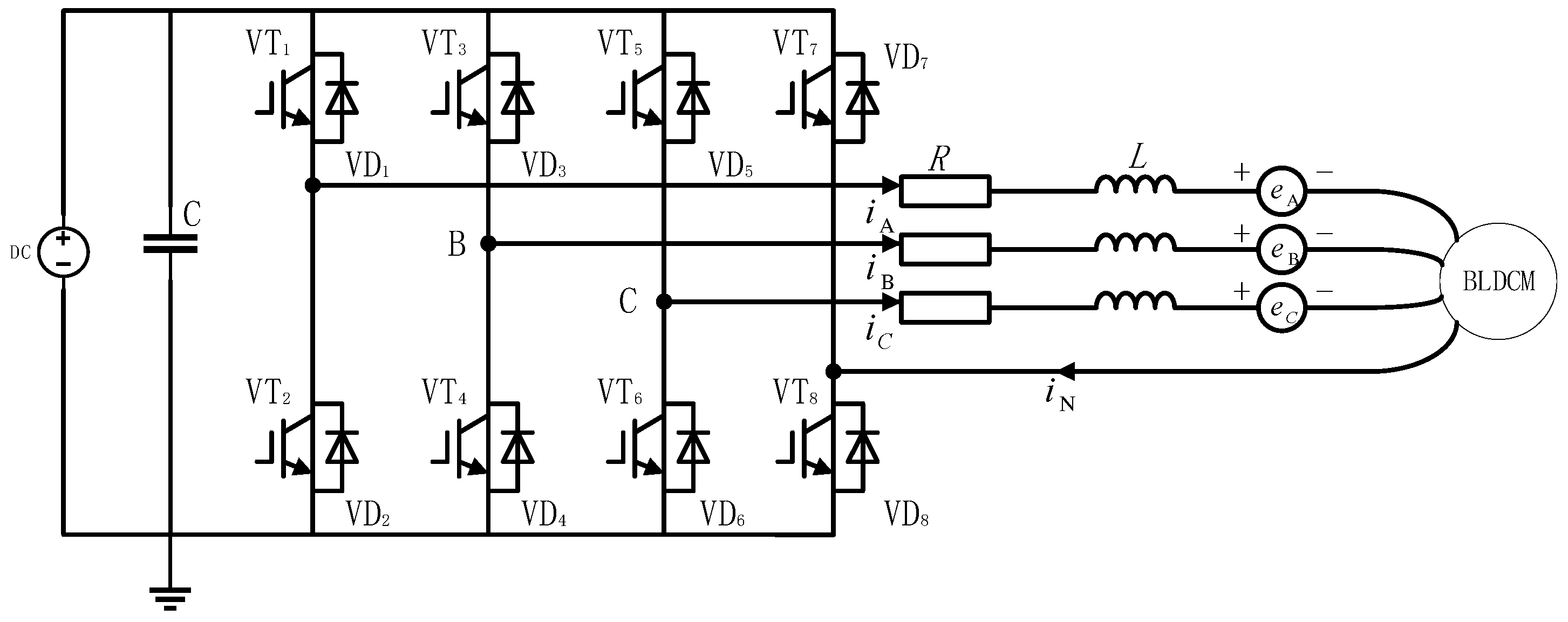
The zero-sequence component of the back-EMF in BLDCMs accounts for a significant proportion. However, in a conventional three-leg inverter, the sum of the three-phase stator currents is constrained to zero, which prevents the zero-sequence back-EMF from contributing to torque production. To address this limitation, this paper introduces an additional bridge leg to the conventional three-leg inverter and connects it to the neutral point of the motor windings, as shown in Figure 4, This configuration provides a current path for the zero-sequence component, enabling the zero-sequence current to interact with the corresponding back-EMF and generate an additional torque component.
Considering the zero-sequence component of the back-EMF, the coordinate transformation matrix C 1 is employed to transform the three-phase back-EMFs of phases A, B, and C into the corresponding components in the α-, β-, and 0-axes reference frame.
C 1 = 2 3 1 1 2 1 2 0 3 2 3 2 1 2 1 2 1 2
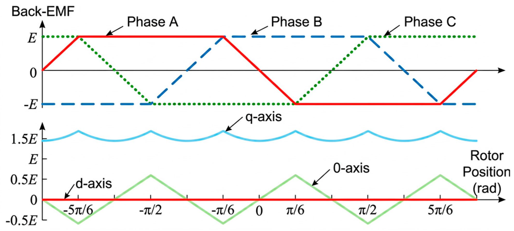
After the transformation in (7), the synthesized non-zero-sequence back-EMF contains components on both the α-axis and the β-axis. Following the method described in the previous section, the rotation angle of the coordinate transformation is adjusted from θ to θ such that the synthesized non-zero-sequence back-EMF is confined exclusively to the q-axis. Subsequently, the back-EMF components in the α-β-0 reference frame are transformed into the corresponding d-q-0 components using the coordinate transformation matrix C 2 . Figure 5 illustrates the back-EMFs of phases A, B, and C as well as the corresponding d-, q-, and 0-axis back-EMF components.
C 2 = cos θ sin θ 0 sin θ cos θ 0 0 0 1
By applying the Clarke transformation in (7) and the Park transformation in (8), a d-q-0 reference-frame model is established, which enables a unified representation of both non-zero-sequence and zero-sequence components. The corresponding voltage differential equations are given as follows:
U d U q U 0 = R + P L ω L 0 ω L R + P L 0 0 0 R + P l 0 i d i q i 0 + 0 e q e 0
At this stage, the instantaneous electromagnetic torque can be expressed as follows:
T e = e q i q + e 0 i 0 Ω = k q θ · i q + k 0 θ · i 0
where k q and k 0 are the back-EMF coefficients on the q-axis and 0-axis, respectively. These coefficients are defined as the ratios of the q-axis back-EMFs, e q and e 0 , to the rotor mechanical angular velocity. Both k q and k 0 vary periodically with the rotor mechanical angular velocity Ω .
The optimization objective, namely the copper loss, is defined as follows:
F 4 l e g = i d 2 + i q 2 + i 0 2
As indicated in (11), the goal is to determine i d , i q , and i 0 , which minimize the objective function F 4 l e g under the constraint T e = k q i q + k 0 i 0 .
By further combining this constraint with Equation (10), the optimal solution can be obtained as follows:
F 4 l e g = i d 2 + T e Ω e q + i 0 e q 2 · 2 T e Ω e 0 + e q 2 + e 0 2 i 0
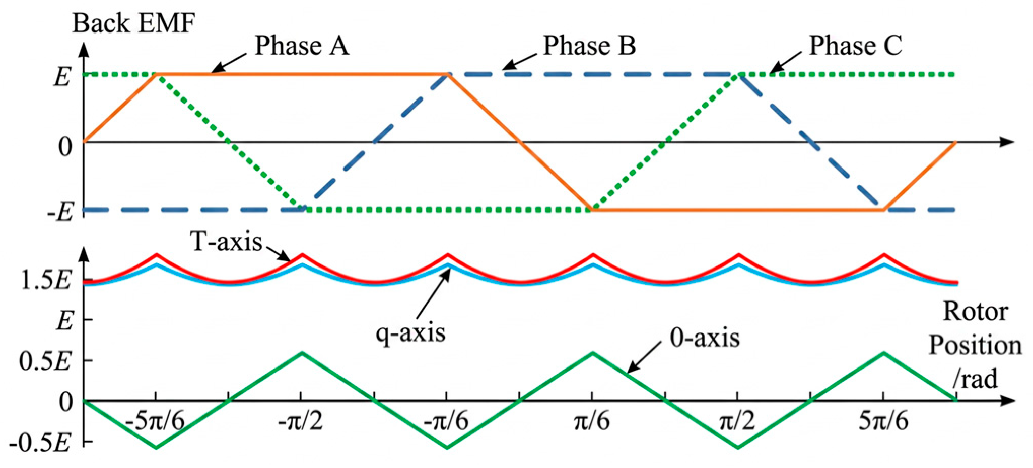
Since torque is jointly determined by e q and e 0 , achieving minimum-copper-loss operation under a four-leg inverter requires the definition of a new coordinate axis on which e q and e 0 can be synthesized into an overall back-EMF e T . This allows the torque equation to be simplified as T e = k T i T . To this end, the transformation matrix C 3 is introduced to construct a new M T ρ reference frame. By selecting an appropriate transformation angle θ 2 , the synthesized back-EMF is aligned entirely along the T-axis. The corresponding coordinate transformation expression and matrix are provided in (13). Figure 6 illustrates the back-EMF of phases A, B, and C, as well as the corresponding q-, 0-, and T-axes components.
e Μ e T e ρ = C 3 e d e q e 0 , C 3 = 1 0 0 0 c o s θ 2 s i n θ 2 0 s i n θ 2 c o s θ 2
Among these,
θ 2 = arctan e 0 θ e q θ
At this stage, the back-EMF of the motor is fully synthesized along the T-axis. The T-axis current i T required to produce the desired output torque T e can then be determined.
i T = T e Ω e T = T e k T
where k T denotes the back-EMF coefficient on the T-axis, defined as the ratio of the T-axis back—EMF e T , which varies periodically with the rotor position, to the rotor mechanical angular velocity Ω .
In the proposed reference frame, to minimize the copper loss i M 2 + i T 2 + i ρ 2 while delivering the required output torque T e = k T i T , the currents along the M-axis and the ρ -axis, which do not contribute to torque production, should be set to zero. Consequently, the optimal current is given by i T = T e / k T .
By combining (10), (13), and (15), the corresponding current expressions can be obtained:
k q θ = k T θ cos θ 2 , k 0 θ = k T θ sin θ 2
Furthermore, since C 3 is a power-invariant transformation matrix, the required q-axis current and the 0-axis currents for producing the desired torque T e can be determined by applying the inverse of matrix C 3 .
i d i q i 0 = C 3 Τ i M i T i ρ = 1 0 0 0 cos θ 2 sin θ 2 0 sin θ 2 cos θ 2 i M i T i ρ
Thus,
i d = 0 , i q = i T cos θ 2 , i 0 = i T sin θ 2

2.2.2. Construction of the MTPA Control System with Zero-Sequence Current Injection

Minimum-copper-loss operation is a key requirement for achieving high efficiency in BLDCMs. Under the condition of delivering the same electromagnetic torque, the introduction of zero-sequence current allows part of the torque to be produced by the zero-sequence component, thereby reducing the torque burden on the non-zero-sequence current. By optimally allocating the zero-sequence current and the non-zero-sequence current, it becomes possible to further reduce the total stator copper loss, which is proportional to the sum of the squares of the three-phase currents.
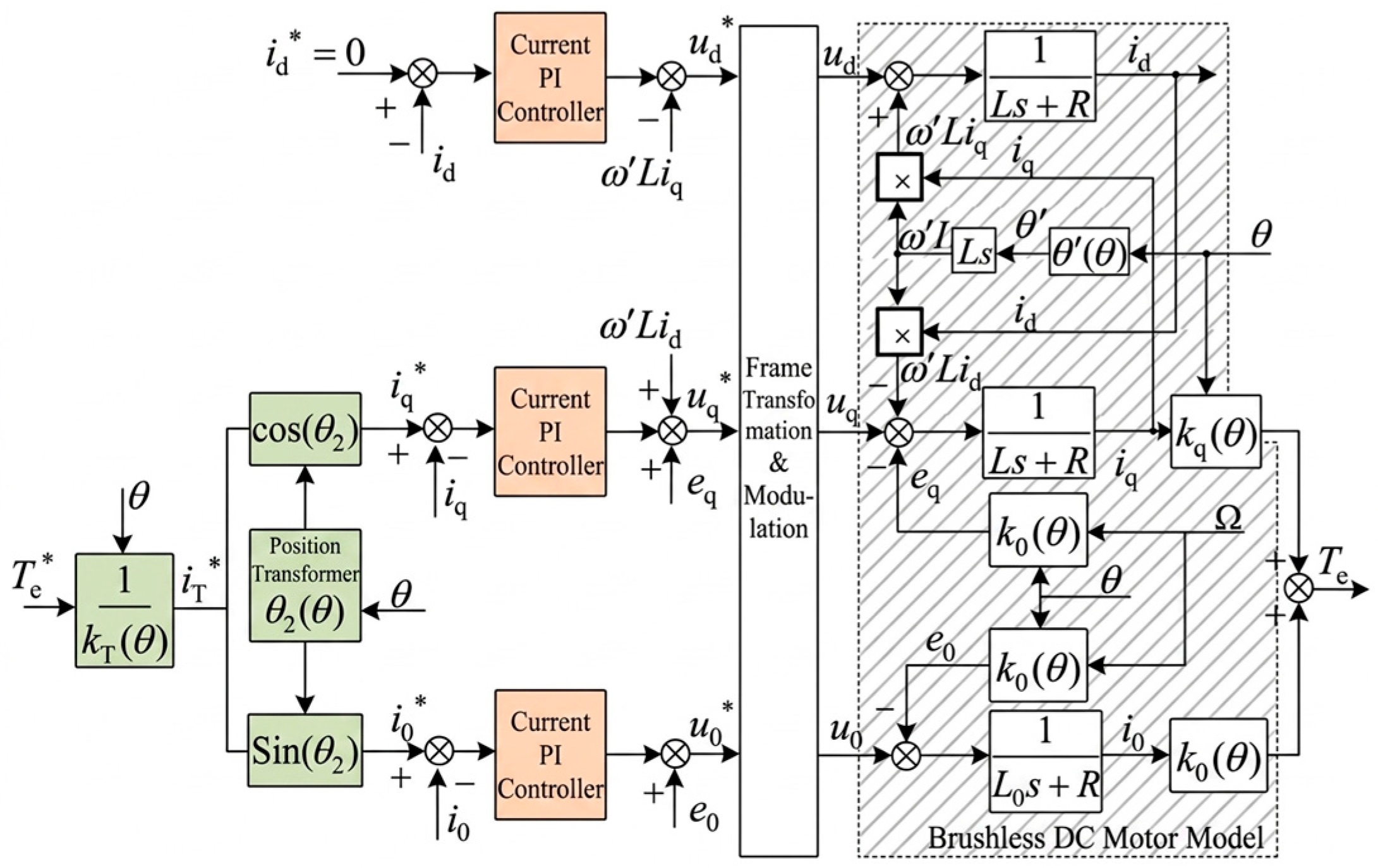
Based on (7), (8), (9), (15), and (18), a control system is constructed to realize minimum-copper-loss operation of the BLDC motor under a four-leg inverter, as illustrated in Figure 7.
From (18), i q and i 0 are non-constant values that vary periodically with rotor position θ . Conventional PI controllers inherently exhibit steady-state errors when tracking such periodic signals, which results in torque ripple and increased copper losses. To address this issue, in addition to the conventional PI cascade compensation for the q-axis and 0-axis currents, a reference-torque feedforward compensation scheme is introduced for each axis. This feedforward link computes and compensates the back-EMF and inductive voltage drop in real time based on the motor model.
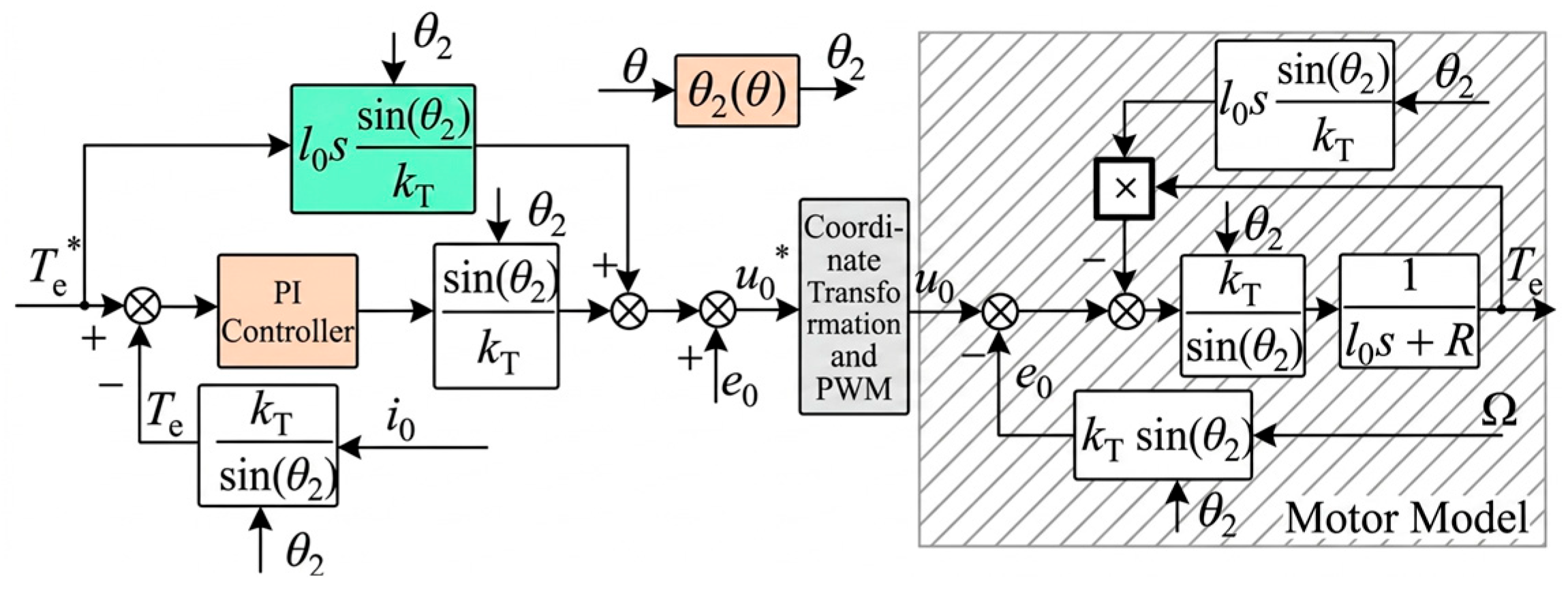
By combining the q-axis and 0-axis voltage differential equations in (9) with (16), the corresponding control expressions can be derived as
u q = cos θ 2 k T R + L p T e + L p cos θ 2 k T · T e + ω L i d + e q u 0 = sin θ 2 k T R + l 0 p T e + L p sin θ 2 k T · T e + e 0
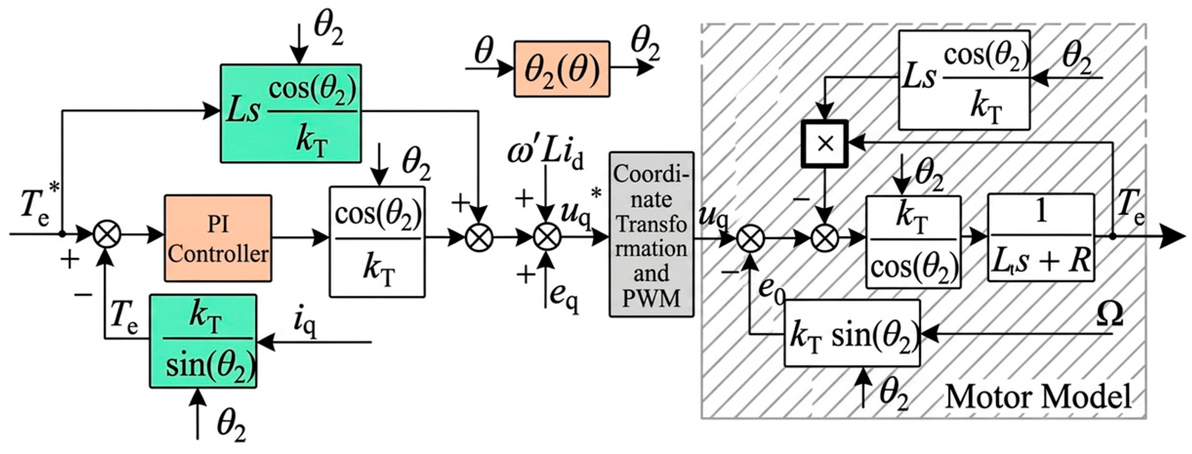
From (19), the closed-loop torque control block diagram for the q-axis can be derived, as shown in Figure 8. In this configuration, neglecting the delay of the main circuit is ignored, and assuming that k T in the controller is identical to the actual k T of the motor, steady-state-error-free negative-feedback control of the electromagnetic torque can be achieved. Compared with the control system block diagram in Figure 7, the proposed scheme only introduces a reference-torque feedforward compensation link, resulting in a simple structure and easy implementation.
Similarly, the closed-loop torque control block diagram for the 0-axis can be derived, as shown in Figure 9.
The torque calculation formulation of the proposed minimum-copper-loss control strategy based on zero-sequence current injection under a four-leg inverter explicitly incorporates the instantaneous back-EMF of the BLDC motor. The analysis indicates that if the actual d-, q-, and 0-axis currents can accurately track their corresponding reference currents in real time, torque-ripple-free operation can theoretically be achieved. The stability of the proposed MTPA control strategy is guaranteed by the closed-loop current control structure. The q-axis and 0-axis current loops are regulated using PI controllers with appropriately tuned gains. The incorporation of feedforward compensation enhances the dynamic response and reduces phase lag, thereby contributing to improved system stability. Furthermore, the system operates within a bounded region defined by motor parameters and inverter constraints. Experimental results verify that the proposed control system maintains stable operation under both steady-state and transient conditions. The stability is further confirmed through step-response experiments.
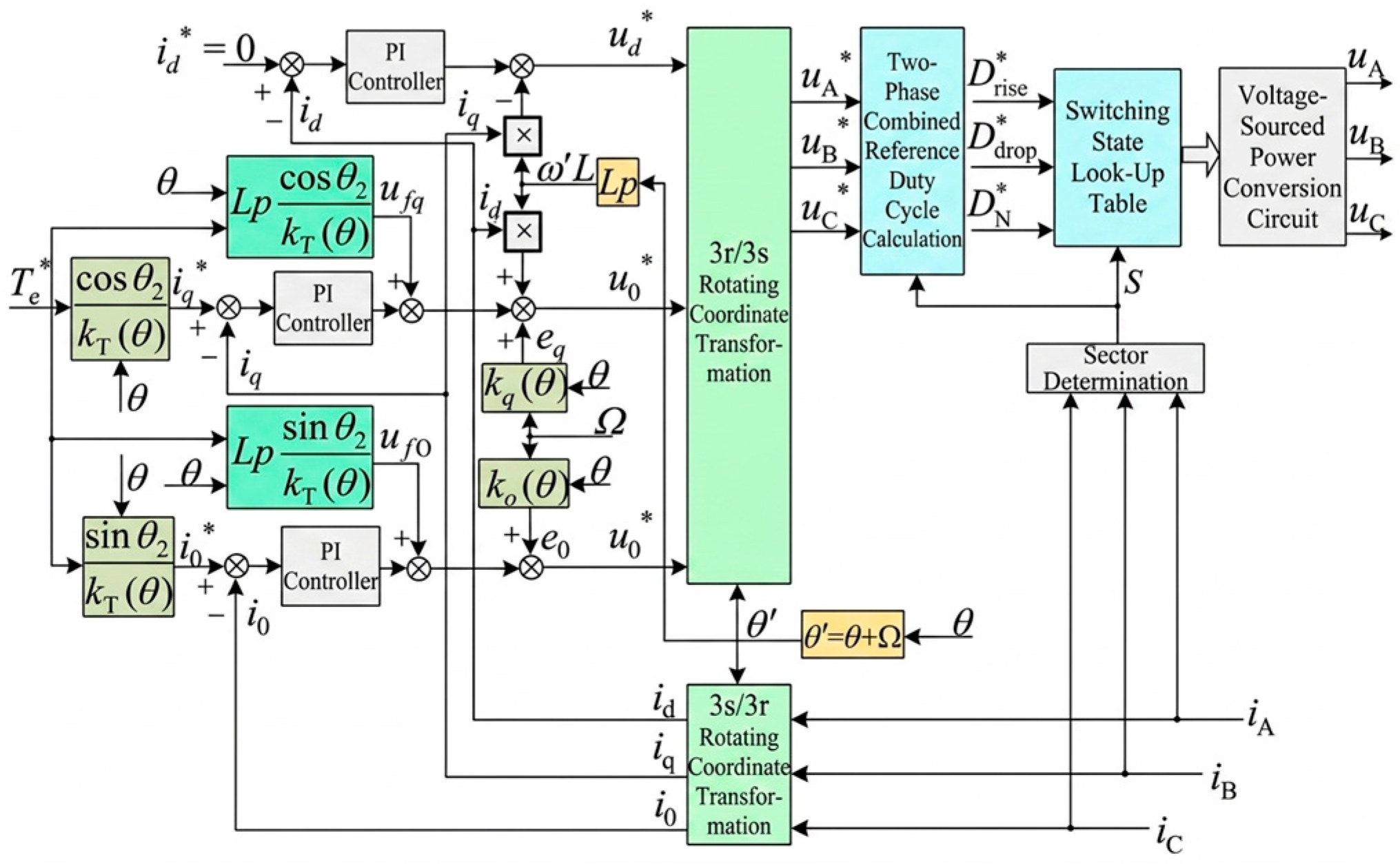
Figure 10 presents the block diagram of the BLDC motor minimum-copper-loss operation control system based on zero-sequence current injection under a four-leg inverter. As shown in the figure, the system uses parameters related to the rotor position, including k q , k 0 , cos θ 2 / k T , sin θ 2 / k T , L p cos θ 2 / k T , and L p sin θ 2 / k T , to calculate the q-axis and 0-axis back electromotive forces e q , e 0 ; the q-axis and 0-axis reference currents i q , i 0 ; and the feedforward compensation voltages u f q , u f 0 . These parameters can be computed offline in advance and stored in a database for rapid retrieval during actual operation. In this control system, the 3s/3r rotating coordinate transformation matrix adopts the C 2 C 1 matrix obtained from (7) and (8), whereas the 3r/3s rotating coordinate transformation matrix is the transpose of C 2 C 1 .
Considering the addition of a fourth bridge arm, the modulation strategy becomes more complex. Accordingly, a dedicated modulation strategy is designed in this paper, as summarized in Table 1 and Table 2. To reduce switching losses, the system is configured such that, at any instant, only two switches among the three-phase bridge arms operate under pulse-width modulation (PWM). Table 1 redefines the sectors based on the directional combinations of the three-phase currents during operation and identifies the rising and falling phases. Table 2 further provides the corresponding switching states in each sector, along with the duty-cycle calculation formulas for the rising-phase, falling-phase, and neutral-line bridge-arm switches. In the tables, 1 and 0 denote the on-state and off-state of the corresponding switch, respectively. D r i s e , D d r o p , and D N   denote the duty cycles of the rising-phase switch, the falling-phase switch, and the neutral-line bridge-arm switch, respectively. u d c denotes the DC bus voltage.

3. Simulation Results and Experimental Confirmation

To validate the theoretical analysis presented in Section 2, this section provides a comprehensive evaluation of the proposed MTPA control strategy. First, the experimental platform and system parameters are described. Then, comparative simulation results are presented to assess the effectiveness of the proposed method. Finally, experimental results are provided to verify its superiority over the conventional control strategy without zero-sequence current injection in terms of copper loss reduction and torque ripple suppression.

3.1. Motor Drive Control Simulation Model

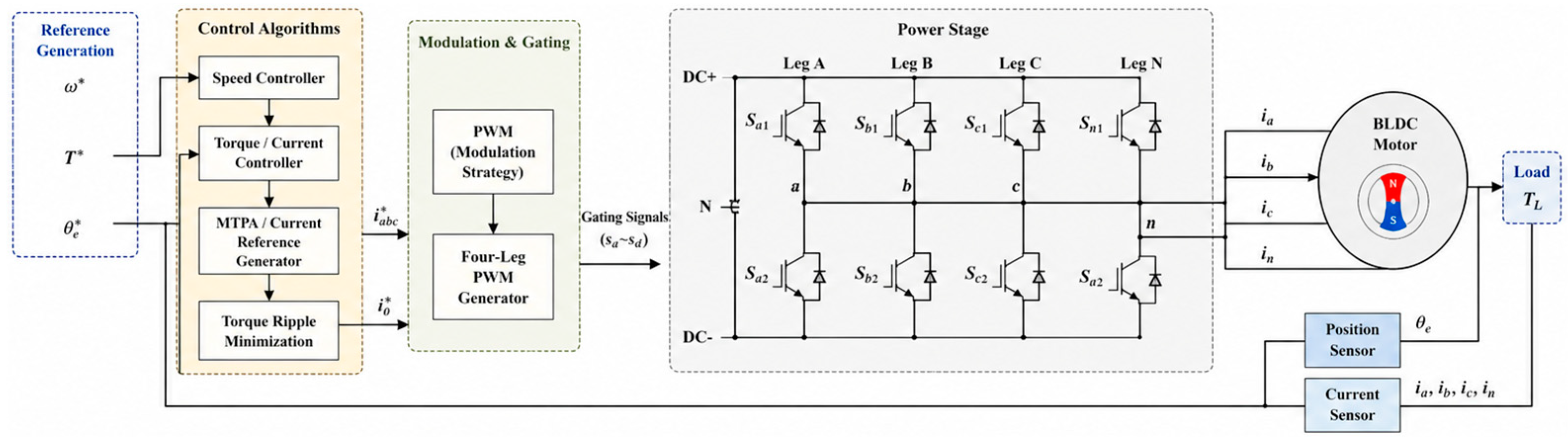
A simulation model of the proposed four-leg inverter-fed BLDC drive system was developed in MATLAB/Simulink to validate the effectiveness of the control strategy. The model consists of a DC source, a four-leg inverter, a BLDC motor, and the associated control system, as illustrated in Figure 11.
The four-leg inverter comprises eight switching devices, with the additional leg connected to the motor neutral point to enable zero-sequence current injection. A carrier-based PWM scheme is employed, with a switching frequency of 20 kHz.
The BLDC motor is modeled in the phase domain, taking into account stator resistance, inductance, and trapezoidal back-EMF. The electromagnetic torque is calculated based on the interaction between phase currents and back-EMF, while the mechanical dynamics are described by the standard motion equation.
The control system consists of the proposed MTPA strategy, current regulators, and a PWM generator. The MTPA algorithm determines the optimal current distribution, including zero-sequence current injection, to minimize copper losses while maintaining the desired torque. PI controllers are employed for current tracking.
A fixed-step solver is adopted with a sampling period of 50 μs, consistent with the control update rate. The sampling frequency is selected to be significantly higher than the electrical frequency of the system to ensure accurate current tracking and adequate dynamic performance.
All simulations were carried out on a personal computer equipped with an Intel Core i7 processor and 16 GB RAM, using MATLAB/Simulink (R2021a).

3.2. Experimental Platform and System Parameters

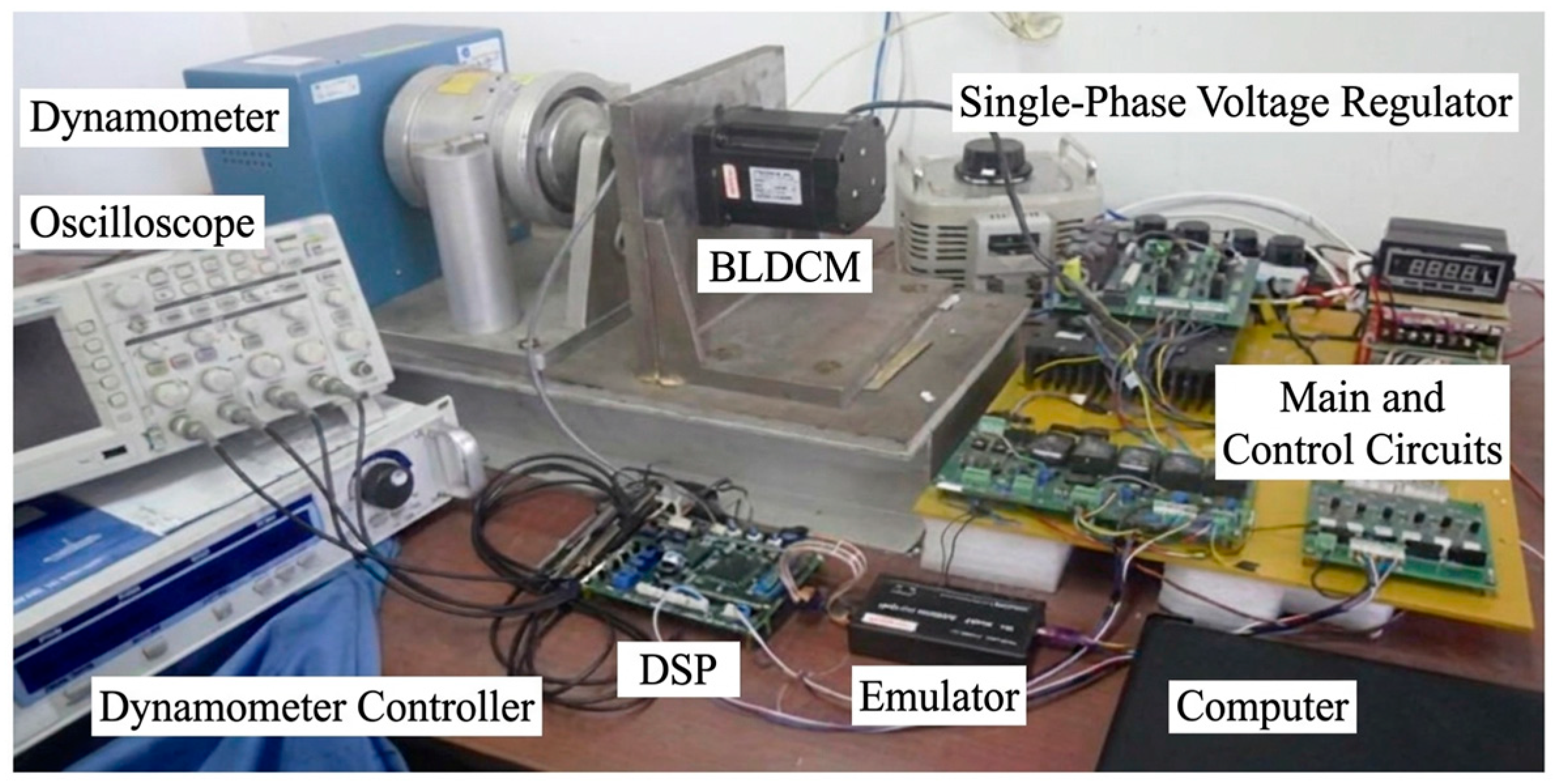
The experimental platform of the control system is shown in Figure 12. It consists of a three-phase, five pole-pair BLDC motor; a magnetic powder dynamometer; a DSP control (TMS320F28335, Texas Instruments (TI), Dallas, TX, USA) with its peripheral circuits; a photoelectric encoder; and a three-/four-leg inverter circuit. The platform is designed to emulate practical operating conditions for evaluating the performance of the proposed strategy. The control program is implemented on the DSP using code composer studio (CCS), which handles signal acquisition (position and current) and generates the switching control signals for the power devices. An oscilloscope (Tektronix DPO2024B, Tektronix, Inc., Beaverton, OR, USA) is used to capture voltage and current waveforms, while a dynamometer (DSP6001, Hangzhou Aihua Instruments Co., Ltd., Hangzhou, China) is employed to apply and measure the load torque. Voltage and current are measured using calibrated sensors with an accuracy of ±0.8%, and the rotor speed is obtained from an encoder with a resolution of 2048 pulses per revolution. The main parameters of the control system are summarized in Table 3.

3.3. Simulation Results

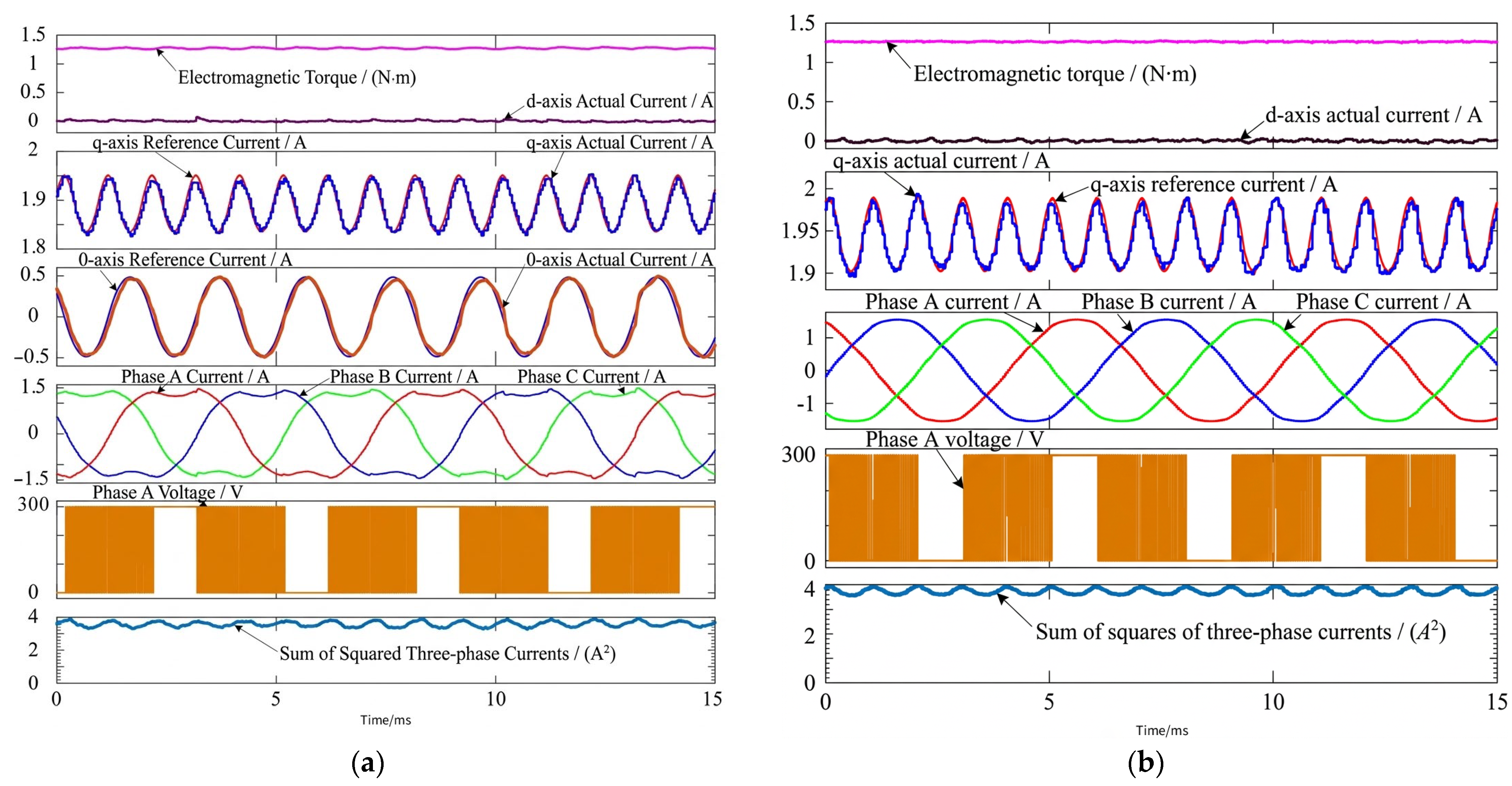
The effectiveness of the proposed strategy is evaluated through comparative analysis with the conventional three-leg inverter-based control method. The motor performance under both strategies is assessed using data obtained from the MATLAB Scope module. Under rated load conditions without zero-sequence current injection (three-leg inverter), the average values of the squared three-phase currents are 3.805 A2 and 3.812 A2 at speeds of 1000 r/min and 2000 r/min, respectively. In contrast, under the proposed strategy with zero-sequence current injection (four-leg inverter), the corresponding values are reduced to 3.568 A2 and 3.574 A2. This represents a reduction of 6.23% and 6.24% at 1000 r/min and 2000 r/min, respectively. These results clearly demonstrate that the proposed strategy significantly lowers copper loss compared with the conventional method. As shown in Figure 13, Figure 14 and Figure 15.
To evaluate the dynamic performance of the proposed strategy, Figure 16 presents the waveforms of the electromagnetic torque and three-phase currents at a motor speed of 1000 r/min, where the reference torque steps from 0.3 N·m to the rated value and returns to 0.3 N·m. When the torque command increases from light load to rated load, the electromagnetic torque rapidly tracks the reference with only a slight overshoot. Similarly, when the torque command decreases back to light load, the torque is quickly regulated to the desired value. A comparable transient behavior is observed in the three-phase currents. Following the step change, the current peaks exhibit a slight overshoot but return to their steady-state values within one switching cycle. These results demonstrate that the proposed control strategy achieves fast dynamic response and accurate torque tracking under step-load conditions.

3.4. Experimental Confirmation

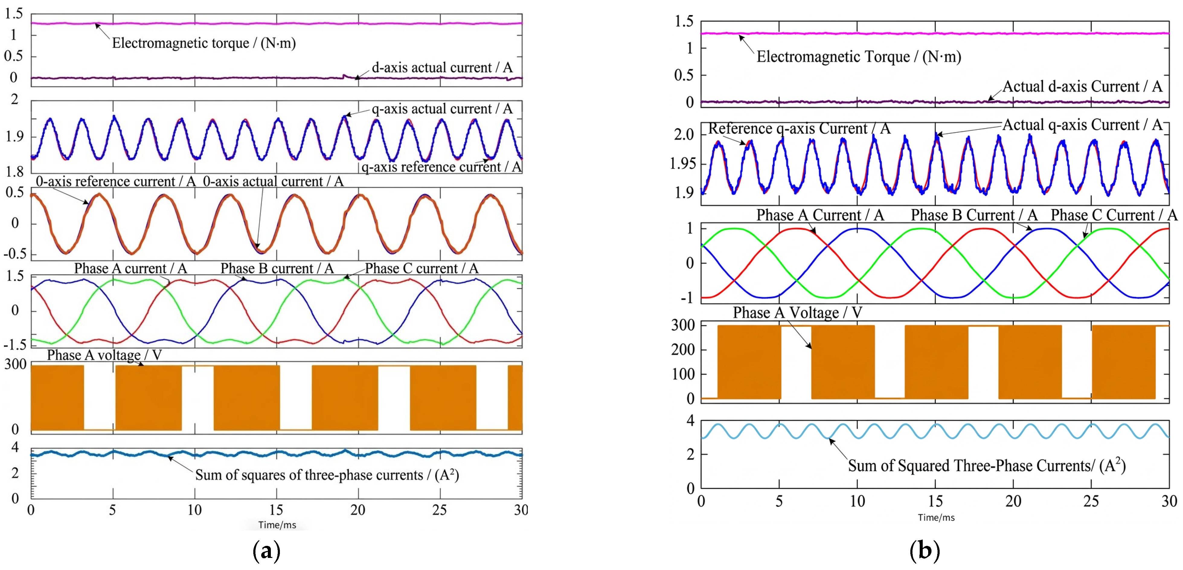
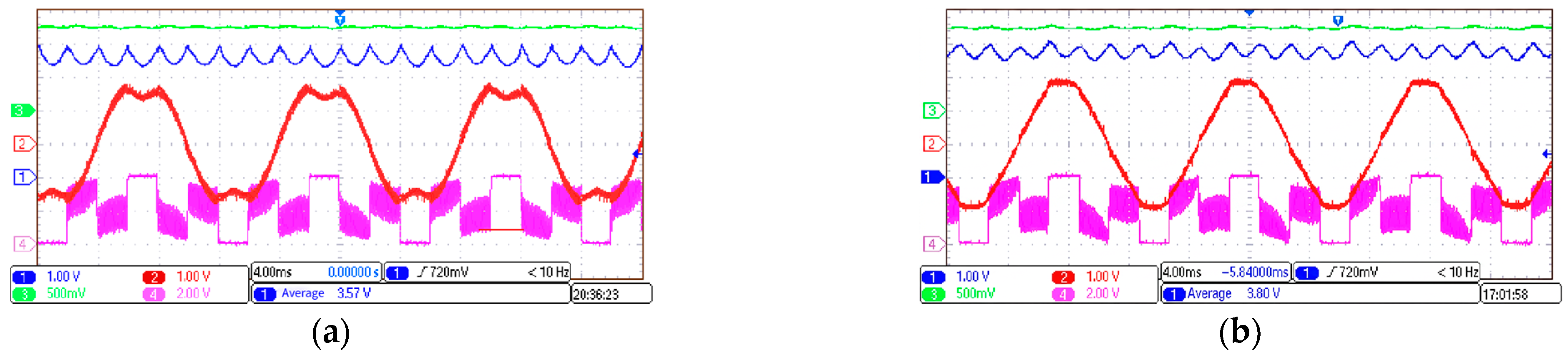
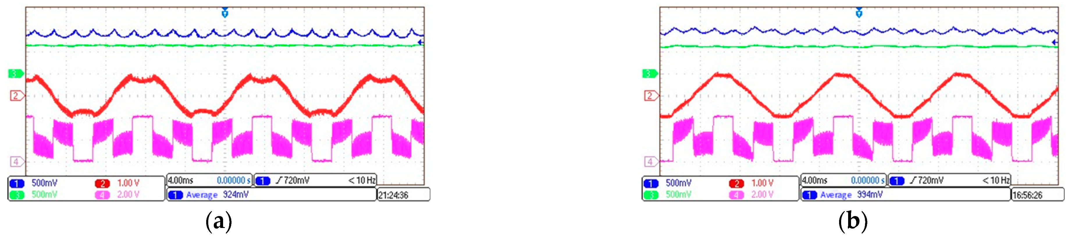
The effectiveness of the proposed strategy is further validated through comparative analysis with the conventional three-leg control method. Figure 17 presents the waveform of the squared three-phase currents at rated load and 1000 r/min, where the left and right subfigures correspond to the proposed strategy and the conventional method, respectively. Due to the limitation of the DA output module, which can only output positive values, a 1 A offset is added to the measured d-axis current, while a 2 A offset is applied to both the reference and actual 0-axis currents. The results show that, although the peak values of the squared three-phase currents are nearly identical under both strategies, the proposed method achieves a lower valley value. According to oscilloscope measurements, the average values are 3.57 A2 for the proposed strategy and 3.80 A2 for the conventional method. This corresponds to a reduction of 6.05% in copper loss, demonstrating the effectiveness of the proposed approach.
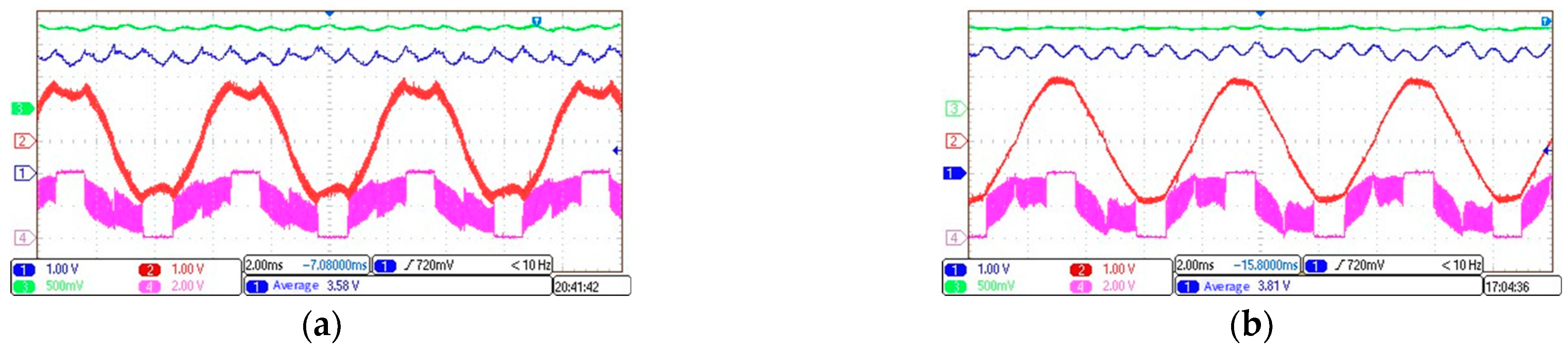
Figure 18 presents the waveform of the squared three-phase currents at rated load and a speed of 2000 r/min, comparing the current characteristics of the proposed strategy with those of the conventional control method. The results indicate that the average value of the squared three-phase currents is reduced to 3.58 A2 under the proposed strategy, compared with 3.81 A2 for the conventional method. This corresponds to a reduction of 6.04% in copper loss. These results demonstrate that the proposed strategy remains effective under high-speed, rated-load conditions, achieving reduced current magnitude and improved efficiency.
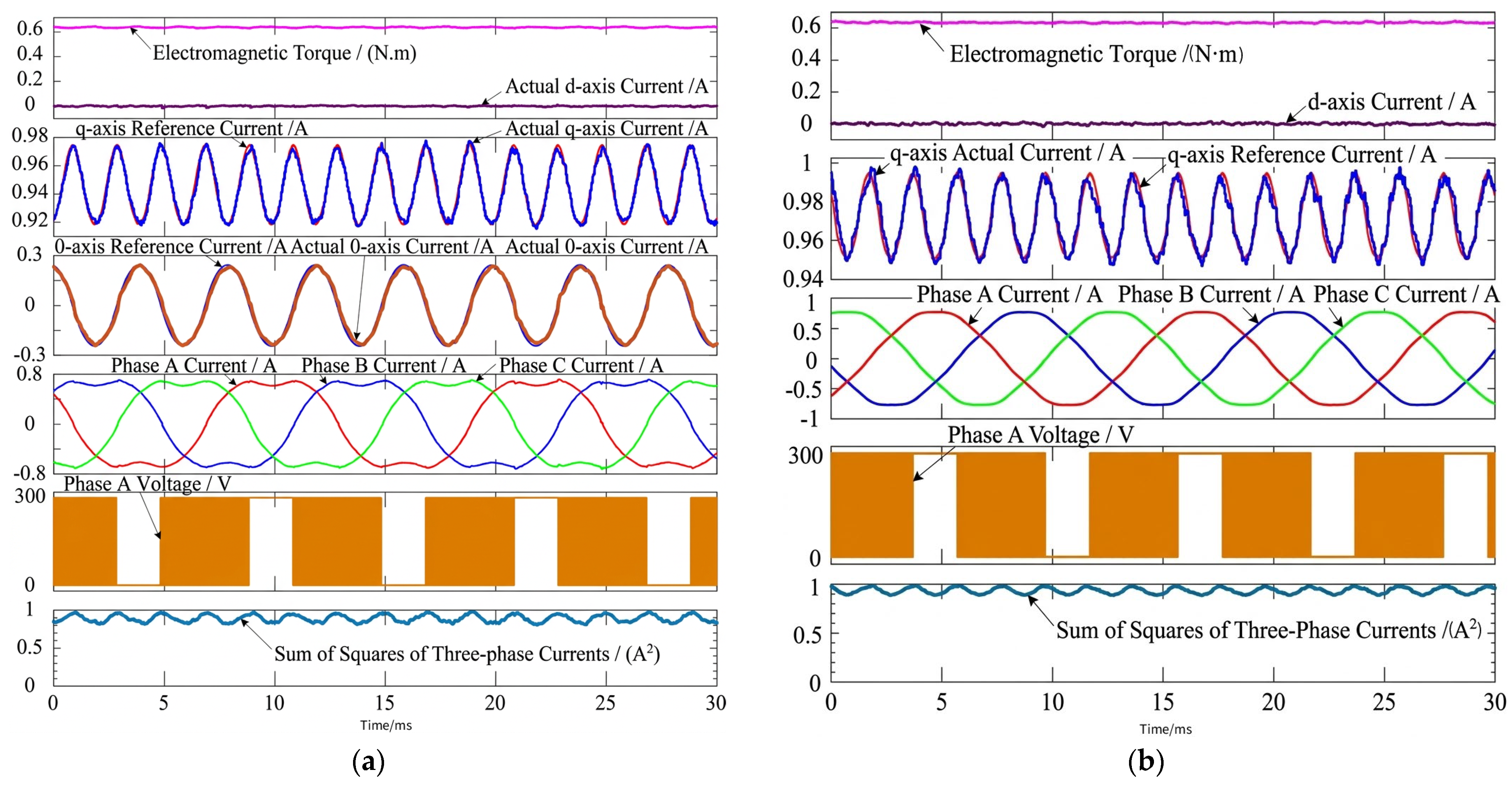
Figure 19 presents the waveform of the squared three-phase currents at half rated load and 1000 r/min. According to oscilloscope measurements, the average value of the squared three-phase currents is 0.924 A2 under the proposed strategy, compared with 0.994 A2 for the conventional control method. This corresponds to a reduction of 7.04% in copper loss. These results demonstrate that under half rated load and low-speed operation, the proposed strategy still exhibits a significant advantage over the conventional control strategy in reducing motor copper loss.
Based on the experimental results under both rated-load and half-rated-load conditions, it is confirmed that for the same torque and speed, the proposed strategy achieves minimum-copper-loss operation. A comparison of the average squared three-phase currents indicates that copper loss is reduced by more than 6% compared with the conventional control strategy. To further illustrate the effectiveness of the proposed method, the experimental results under various operating conditions are summarized in Table 4. The q-axis and 0-axis currents accurately track their respective reference values, demonstrating the effectiveness of the control scheme. These results not only validate the superiority of the proposed strategy in reducing copper loss but also highlight its potential for improving overall motor performance and control accuracy.
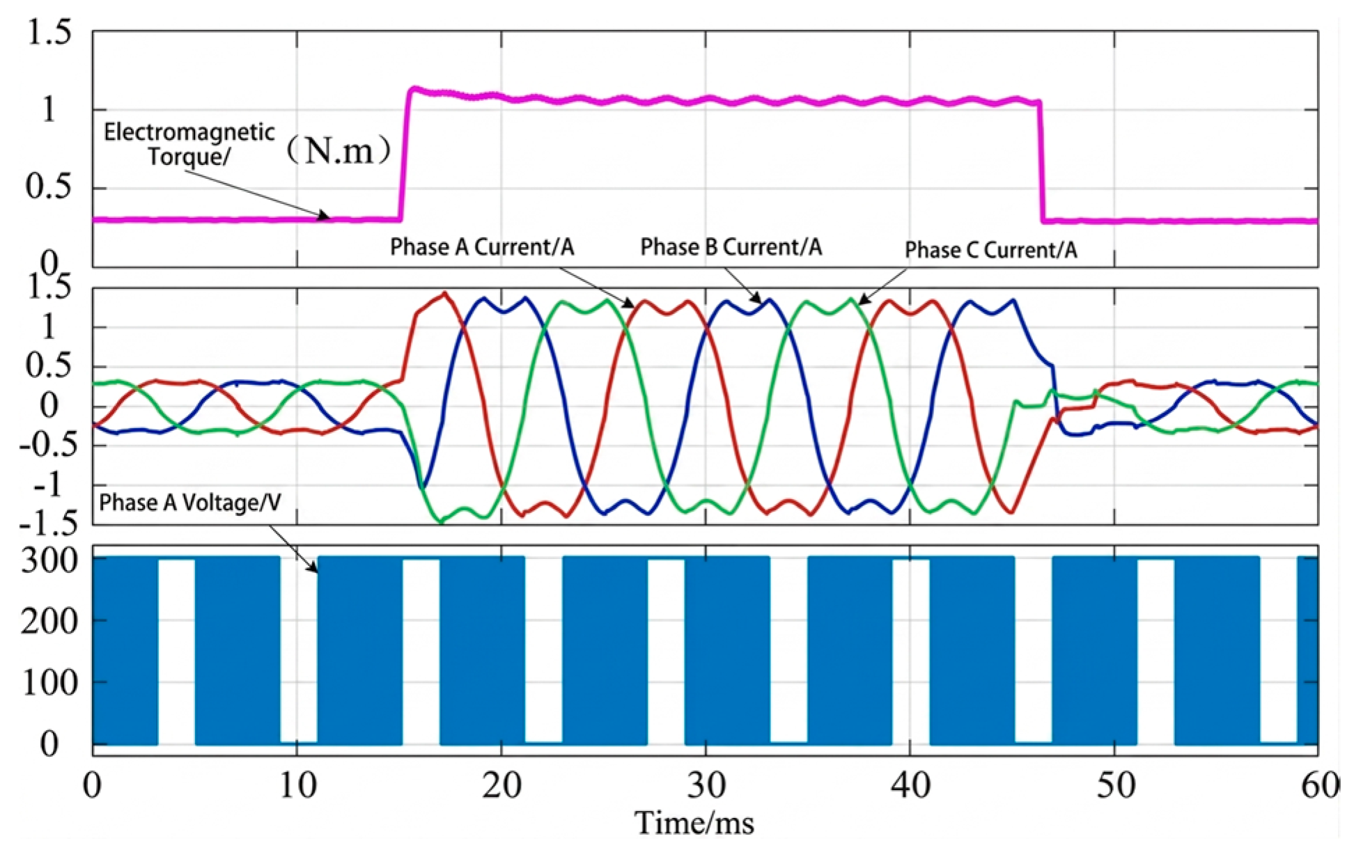
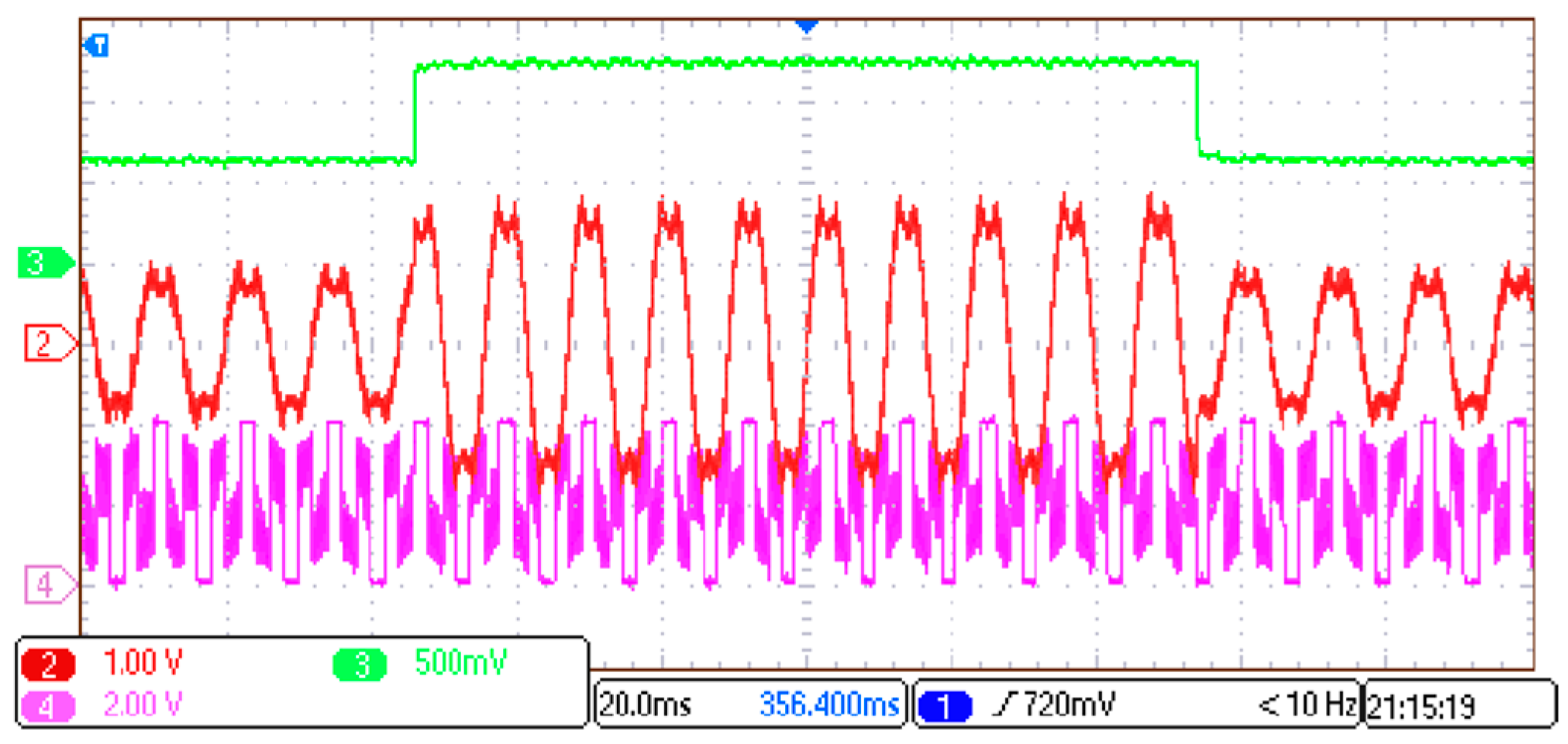
Figure 20 presents the waveforms under the proposed strategy at a motor speed of 1000 r/min, where the reference torque steps from 0.635 N·m to the rated value and then returns to 0.635 N·m after a short interval.
When the torque command changes abruptly, the electromagnetic torque rapidly tracks the corresponding reference value with minimal delay. The stator current exhibits only a brief transient distortion at the instant of the step change and quickly returns to its steady-state waveform. These results demonstrate that the proposed strategy achieves fast dynamic response and stable current behavior under transient conditions.
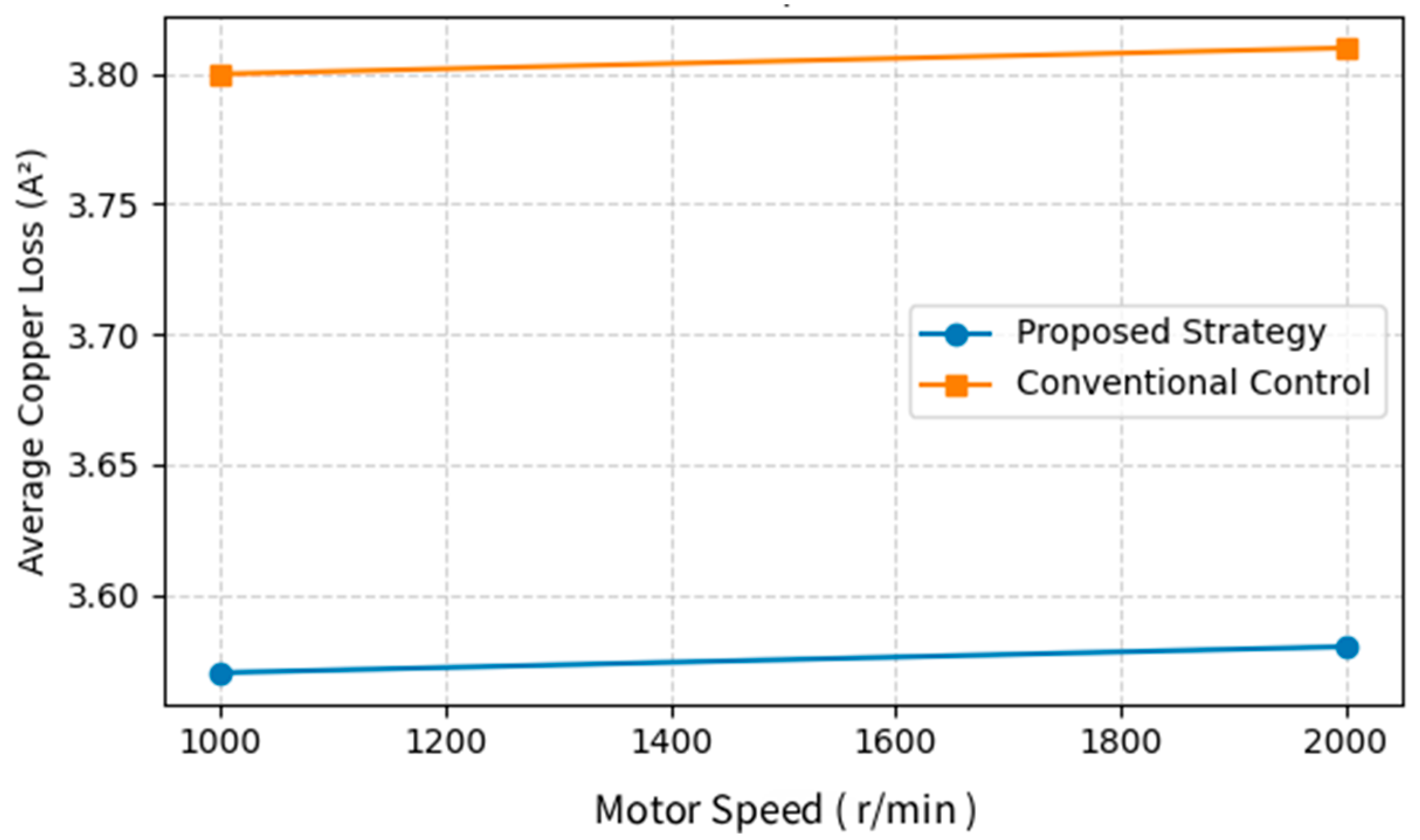
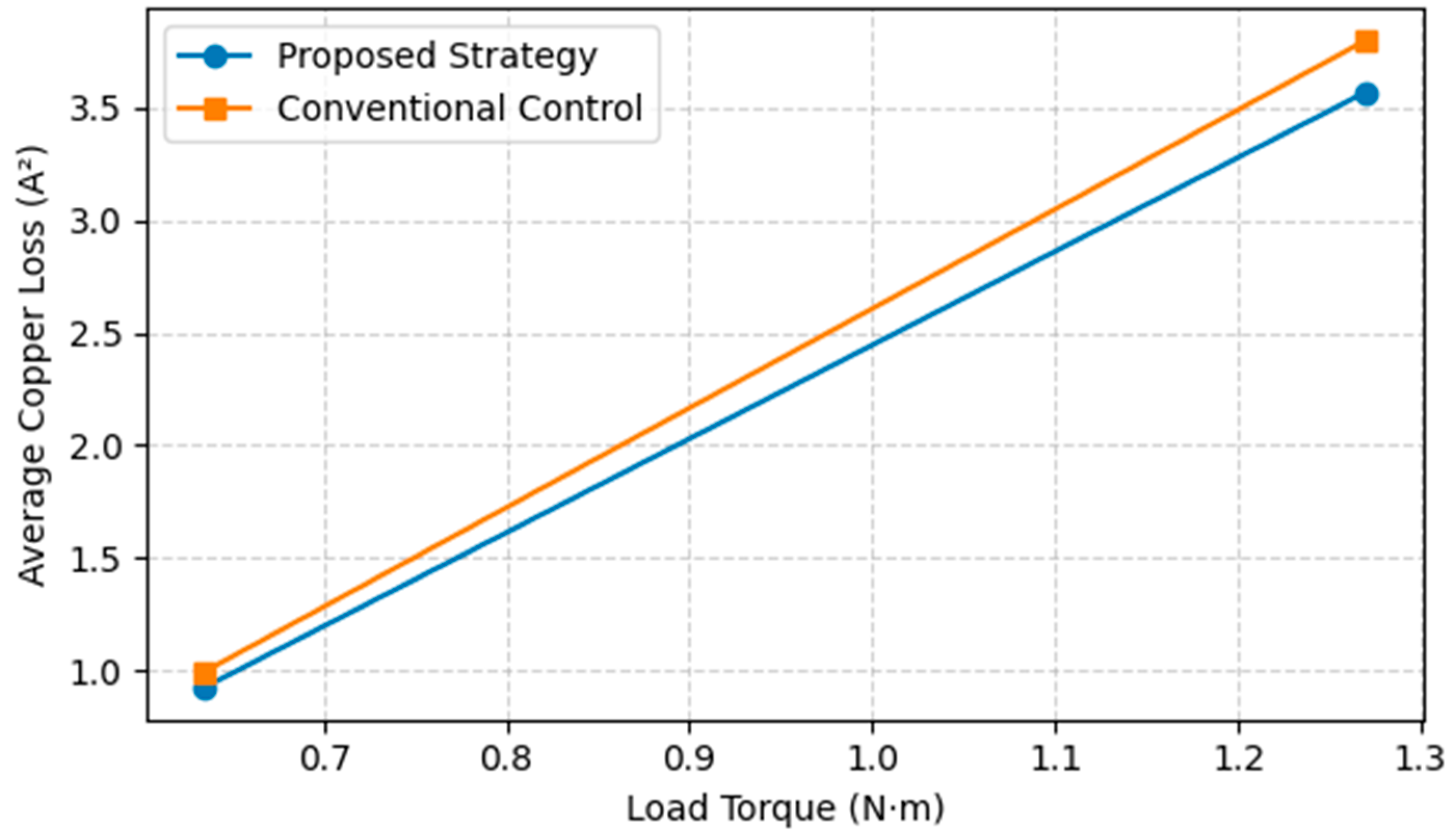
To provide a more quantitative and comprehensive presentation of the results, we additionally plotted the dependence of copper loss on motor speed at rated torque and on load torque at a fixed speed of 1000 r/min.
As shown in the Figure 21 and Figure 22, the proposed strategy consistently reduces copper loss by more than 6% compared with the conventional three-leg control under different operating conditions, demonstrating its effectiveness in minimizing copper loss while maintaining the desired torque.

3.5. System Efficiency and Life-Cycle Cost Analysis

Since the main purpose of the proposed strategy is reducing copper loss, the system-level efficiency is further analyzed based on the measured current index and the motor parameters. For the same speed and load torque, the output mechanical power remains unchanged, and therefore the reduction in copper loss directly contributes to the improvement of motor-side efficiency. Table 5 lists the estimated copper loss under representative operating conditions. At 1.27 N·m and 1000 r/min, the copper loss decreases from 11.59 W to 10.89 W. A similar reduction is observed at 2000 r/min. Under half-rated load, the copper loss decreases from 3.03 W to 2.82 W. These results indicate that the proposed strategy provides a consistent reduction in stator copper loss.
It should be noted that the four-leg inverter introduces additional semiconductor and gate-driver losses. However, the fourth leg mainly carries the zero-sequence current and does not require an increase in the current rating of the three main phase legs. Therefore, the additional inverter loss is limited. The net efficiency benefit depends on the balance between the reduced motor copper loss and the additional inverter loss, which is further evaluated in the life-cycle cost analysis.
As shown in the Table 6, a simplified life-cycle cost analysis was conducted to evaluate the cost-effectiveness of the proposed four-leg MTPA control.
For the 400 W laboratory prototype used in this study, the absolute copper-loss reduction is approximately 0.2–0.7 W under the tested operating conditions. Therefore, the direct electricity-cost saving is limited if the annual operating time is short. However, the proposed method becomes more cost-effective in high-duty-cycle applications or when scaled to higher-power BLDC drives, because the saved copper loss increases with the current level. In addition, the reduced copper loss contributes to lower winding temperature and improved thermal reliability, which may further reduce maintenance cost and extend motor lifetime.

4. Discussion

To minimize the copper loss of BLDCMs while maintaining the same electromagnetic torque, this paper proposes an MTPA control strategy based on zero-sequence current injection. The main conclusions are summarized as follows.
(1) Fourier analysis of the trapezoidal back-EMF reveals the presence of significant zero-sequence components. To effectively utilize these components, a fourth bridge leg is added to the conventional three-leg inverter, enabling zero-sequence current flow. Theoretical analysis demonstrates that this approach can further reduce copper loss.
(2) The proposed minimum-copper-loss strategy under a four-leg inverter explicitly considers the torque contributions of both harmonic back-EMF components and harmonic currents. In addition, a feedforward compensation scheme is introduced after coordinate transformation, which effectively mitigates torque ripple caused by the limited tracking capability of PI controllers for time-varying reference signals.
(3) Both simulation and experimental results verify the effectiveness of the proposed strategy. The results show that copper loss can be reduced by more than 6% under various operating conditions, while maintaining fast dynamic response and accurate torque tracking performance. From an implementation perspective, although the additional bridge leg slightly increases hardware complexity, it enhances controllability of the neutral-point voltage, enabling more flexible current shaping and improved torque density. Furthermore, modern power electronic devices and digital controllers ensure reliable operation of the additional switching leg.

5. Conclusions

This paper proposes an MTPA control strategy for BLDC motor drives based on zero-sequence current injection and a four-leg inverter topology to achieve minimum-copper-loss operation.
The proposed method effectively utilizes the zero-sequence back-EMF component to participate in torque production, thereby reducing the required non-zero-sequence current. Both simulation and experimental results demonstrate that the average squared phase current can be reduced by more than 6% under various operating conditions, indicating a significant reduction in copper loss.
In addition, the proposed strategy exhibits excellent dynamic performance, achieving fast torque response and accurate current tracking under transient conditions. The introduction of feedforward compensation further suppresses torque ripple caused by the limited tracking capability of PI controllers for time-varying reference signals.
From an implementation perspective, although the four-leg inverter slightly increases hardware complexity, it provides enhanced controllability of the neutral-point voltage, enabling flexible current shaping and improved torque density. With the support of modern power electronic devices and digital controllers, reliable real-time operation can be readily achieved.
Furthermore, a system-level efficiency and simplified life-cycle cost analysis were included. The results show that the proposed strategy reduces the stator copper loss under representative operating conditions. Although the fourth inverter leg introduces additional hardware cost and semiconductor loss, the proposed method can be cost-effective in applications with long annual operating hours, high duty cycles, or higher power ratings. The reduced copper loss also contributes to lower thermal stress and improved motor reliability.
Overall, the proposed method offers an effective and practical solution for improving efficiency, reducing copper loss, and enhancing dynamic performance in BLDC motor drive systems, demonstrating strong potential for real-world applications.

Author Contributions

Conceptualization, Z.L. and T.Z.; methodology, Z.L., T.Z. and Z.X.; software, Z.L., T.Z. and Z.X.; validation, T.Z., Z.X. and Z.Y.; writing—original draft preparation, Z.L.; writing—review and editing, T.Z., Z.X. and Z.Y. All authors have read and agreed to the published version of the manuscript.

Funding

This research received no external funding.

Data Availability Statement

The data presented in this study are available from the corresponding author upon reasonable request.

Acknowledgments

The authors would like to thank all the collaborators who provided helpful discussions and support during this work.

Conflicts of Interest

The authors declare no conflicts of interest.

References

  1. Jahns, T.M.; Soong, W.L. Pulsating torque minimization techniques for permanent magnet AC motor drives-a review. IEEE Trans. Ind. Electron. 1996, 43, 321–330. [Google Scholar] [CrossRef]
  2. Kim, D.K.; Lee, K.W.; Kwon, B.I. Commutation torque ripple reduction in a position sensorless brushless DC motor drive. IEEE Trans. Power Electron. 2006, 21, 1762–1768. [Google Scholar] [CrossRef]
  3. Fang, J.; Li, H.; Han, B. Torque ripple reduction in BLDC torque motor with nonideal back EMF. IEEE Trans. Power Electron. 2011, 27, 4630–4637. [Google Scholar] [CrossRef]
  4. Raj, R.A.; Nair, D.S.; George, S. A novel high-voltage gain circuit topology for commutation torque ripple reduction. IEEE Trans. Ind. Appl. 2022, 58, 6227–6236. [Google Scholar] [CrossRef]
  5. Yao, X.; Zhao, J.; Wang, J.; Huang, S.; Jiang, Y. Research on suppressing commutation torque ripple of brushless DC motor based on an auxiliary step-up front end. Proc. CSEE 2020, 40, 3021–3030. [Google Scholar]
  6. Xia, K.; Ye, Y.; Ni, J.; Wang, Y.; Xu, P. Model predictive control method of torque ripple reduction for BLDC motor. IEEE Trans. Magn. 2019, 56, 1–6. [Google Scholar] [CrossRef]
  7. Huang, C.L.; Lee, F.C.; Liu, C.J.; Chen, J.Y.; Lin, Y.J.; Yang, S.C. Torque ripple reduction for bldc permanent magnet motor drive using dc-link voltage and current modulation. IEEE Access 2022, 10, 51272–51284. [Google Scholar] [CrossRef]
  8. Bertoluzzo, M.; Buja, G.; Keshri, R.K.; Menis, R. Sinusoidal versus square-wave current supply of PM brushless DC drives: A convenience analysis. IEEE Trans. Ind. Electron. 2015, 62, 7339–7349. [Google Scholar] [CrossRef]
  9. Kshirsagar, P.; Krishnan, R. High-efficiency current excitation strategy for variable-speed nonsinusoidal back-EMF PMSM machines. IEEE Trans. Ind. Appl. 2012, 48, 1875–1889. [Google Scholar] [CrossRef]
  10. De Castro, A.G.; Guazzelli, P.R.; dos Santos, S.T.; de Oliveira, C.M.; Pereira, W.C.; Monteiro, J.R. Zero sequence power contribution on BLDC motor drives. Part I: A Theoretical Investigation. In Proceedings of the 2018 13th IEEE International Conference on Industry Applications (INDUSCON), Sao Paulo, Brazil, 12–14 November 2018; IEEE: New York, NY, USA, 2018; pp. 1016–1023. [Google Scholar]
  11. Zhang, H.; Dou, M.; Deng, J. Loss-minimization strategy of nonsinusoidal back EMF PMSM in multiple synchronous reference frames. IEEE Trans. Power Electron. 2019, 35, 8335–8346. [Google Scholar] [CrossRef]
  12. Park, S.J.; Park, H.W.; Lee, M.H.; Harashima, F. A new approach for minimum-torque-ripple maximum-efficiency control of BLDC motor. IEEE Trans. Ind. Electron. 2000, 47, 109–114. [Google Scholar] [CrossRef]
  13. Khazaee, A.; Zarchi, H.A.; Markadeh, G.A.; Hesar, H.M. MTPA strategy for direct torque control of brushless DC motor drive. IEEE Trans. Ind. Electron. 2020, 68, 6692–6700. [Google Scholar] [CrossRef]
  14. Khazaee, A.; Zarchi, H.A.; Markadeh, G.R.A. Real-time maximum torque per ampere control of brushless DC motor drive with minimum torque ripple. IEEE Trans. Power Electron. 2019, 35, 1194–1199. [Google Scholar] [CrossRef]
  15. Zhang, Q.; Deng, J.; Fu, N. Minimum copper loss direct torque control of brushless DC motor drive in electric and hybrid electric vehicles. IEEE Access 2019, 7, 113264–113271. [Google Scholar] [CrossRef]
Figure 1. Schematic diagram of the relationship between the three-phase stationary reference frame and the two-axis synchronous rotating reference frame.
Machines 14 00536 g001
Figure 2. Back electromotive force waveforms on the d-axis and q-axis under the conventional coordinate transformation.
Machines 14 00536 g002
Figure 3. Fourier decomposition spectrum of the ideal back electromotive force waveform.
Machines 14 00536 g003
Figure 4. Equivalent circuit of the brushless DC motor under a four-leg inverter.
Machines 14 00536 g004
Figure 5. Back electromotive forces of phases A, B, and C and the d-, q-, and 0-axis back electromotive forces.
Machines 14 00536 g005
Figure 6. Back electromotive forces of phases A, B, and C and the q-, 0-, and T-axis back electromotive forces.
Machines 14 00536 g006
Figure 7. Control system for minimum-copper-loss operation based on zero-sequence current injection under a four-leg inverter.
Machines 14 00536 g007
Figure 8. Schematic diagram of q-axis component control for minimum-copper-loss operation based on zero-sequence current injection under a four-leg inverter.
Machines 14 00536 g008
Figure 9. Schematic diagram of 0-axis component control for minimum-copper-loss operation based on zero-sequence current injection under a four-leg inverter.
Machines 14 00536 g009
Figure 10. Block diagram of the brushless DC motor minimum-copper-loss operation control system based on zero-sequence current injection under a four-leg inverter.
Machines 14 00536 g010
Figure 11. Simulation block diagram.
Machines 14 00536 g011
Figure 12. Experimental platform of the control system.
Machines 14 00536 g012
Figure 13. Comparison of simulation waveforms at rated load and a speed of 1000 r/min: (a) waveforms under the proposed strategy; (b) waveforms under the three-leg strategy.
Machines 14 00536 g013
Figure 14. Comparison of simulation waveforms at rated load and a speed of 2000 r/min: (a) waveforms under the proposed strategy; (b) waveforms under the three-leg strategy.
Machines 14 00536 g014
Figure 15. Comparison of simulation waveforms at half rated load and a speed of 1000 r/min: (a) waveforms under the proposed strategy; (b) waveforms under the three-leg strategy.
Machines 14 00536 g015
Figure 16. Simulation waveforms under the proposed strategy when the reference torque steps at a motor speed of 1000 r/min.
Machines 14 00536 g016
Figure 17. Comparison of waveforms of the sum of squares of the three-phase currents at rated load and a speed of 1000 r/min: (a) waveforms under the proposed strategy; (b) waveforms under the three-leg strategy.
Machines 14 00536 g017
Figure 18. Comparison of waveforms of the sum of squares of the three-phase currents at rated load and a speed of 2000 r/min: (a) waveforms under the proposed strategy; (b) waveforms under the three-leg strategy.
Machines 14 00536 g018
Figure 19. Comparison of waveforms of the sum of squares of the three-phase currents at half rated load and a speed of 1000 r/min: (a) waveforms under the proposed strategy; (b) waveforms under the three-leg strategy.
Machines 14 00536 g019
Figure 20. Experimental waveforms under the proposed strategy when the reference torque steps at a motor speed of 1000 r/min.
Machines 14 00536 g020
Figure 21. Dependence of copper loss on motor speed at rated load.
Machines 14 00536 g021
Figure 22. Dependence of copper loss on load torque at 1000 r/min.
Machines 14 00536 g022
Table 1. Sector division and definitions of the rising and falling phases.
Sector SSector Division ConditionDefinition of Rising and Falling Phases
I i A 0 i B < 0 i C < 0 AC, AB
II i A 0 i B 0 i C < 0 BC, AC
III i A < 0 i B 0 i C < 0 BA, BC
IV i A < 0 i B 0 i C 0 CA, BA
V i A < 0 i B < 0 i C 0 CB, CA
VI i A 0 i B < 0 i C 0 AB, CB
Table 2. Switch states in each sector and duty-cycle calculation for the rising-phase, falling-phase, and neutral-line bridge-arm switches.
Sector SSwitch StatesRising/Falling Phases Duty Cycle of the Neutral-Line Bridge-Arm Switch
I 100 D d r o p 0 D r i s e D N 0 D r i s e = u A u C / u d c , D d r o p = u A u B / u d c , D N = 1 u A / u d c
II D d r o p 0 D r i s e 0010 D N D r i s e = u B u C / u d c , D d r o p = u A u C / u d c , D N = 1 + u C / u d c
III 0 D r i s e 100 D d r o p D N 0 D r i s e = u B u A / u d c , D d r o p = u B u C / u d c , D N = 1 u B / u d c
IV 01 D d r o p 0 D r i s e 00 D N D r i s e = u C u A / u d c , D d r o p = u B u A / u d c , D N = 1 + u A / u d c
V 0 D d r o p 0 D r i s e 10 D N 0 D r i s e = u C u B / u d c , D d r o p = u C u A / u d c , D N = 1 u C / u d c
VI D r i s e 001 D d r o p 00 D N D r i s e = u A u B / u d c , D d r o p = u C u B / u d c , D N = 1 + u B / u d c
Table 3. Control system parameters.
ParameterValueParameterValue
Rated voltage300 VPhase resistance3.05 Ω
Rated current1.5 APhase self-inductance0.0155 H
Rated power400 WMutual inductance between phases−0.0075 H
Rated torque1.27 (N·m)Encoder resolution2048 PPR
Rated speed3000 rpmControl period50 μs
Number of pole pairs5Switching frequency20 kHz
Table 4. Comparison of the experimental results of minimum-copper-loss operation between the proposed strategy and the control strategy.
Torque 1.27 N·m
Speed 1000 r/min
Torque 1.27 N·m
Speed 2000 r/min
Torque 0.635 N·m
Speed 1000 r/min
Proposed strategy3.57 A23.58 A20.924 A2
Control strategy3.80 A23.81 A20.994 A2
Percentage reduction in copper loss6.05%6.04%7.04%
Table 5. Estimated copper loss and efficiency improvement under representative operating conditions.
TorqueSpeed/r/minOutput
Power/W
P c u , c o n v /W P c u , p r o p /WCopper-Loss
Reduction/W
Copper-Loss
Reduction/%
1.271000133.011.5910.890.706.05
1.272000266.011.6210.920.706.04
0.635100066.53.032.820.217.04
Table 6. Simplified life-cycle cost analysis of the proposed strategy.
ItemExpression/AssumptionValue Used in Analysis
Additional hardwareFourth inverter leg, gate driver, PCB overheadApplication-dependent
Copper-loss reductionFrom experiments0.21–0.70 W
Additional inverter lossEstimated/sensitivity0.1–0.3 W
Net saved power P c u P i n v 0–0.6 W for prototype
Annual operating time H y e a r 1000–6000 h
Electricity price C e 0.10–0.20 USD/kwh
Payback period C a d d / C s a v e Depends on power and duty cycle
Disclaimer/Publisher’s Note: The statements, opinions and data contained in all publications are solely those of the individual author(s) and contributor(s) and not of MDPI and/or the editor(s). MDPI and/or the editor(s) disclaim responsibility for any injury to people or property resulting from any ideas, methods, instructions or products referred to in the content.