
Article

Effect of Needle Opening on Sediment Erosion and Entropy Production in a Pelton Turbine

1
State Key Laboratory of Hydroscience and Engineering, Department of Energy and Power Engineering, Tsinghua University, Beijing 100084, China
2
College of Hydraulic Science and Engineering, Yangzhou University, Yangzhou 225100, China
3
Datang Xizang Energy Development Co., Ltd., Lhasa 850001, China
4
Harbin Electric Machinery Co., Ltd., Harbin 150040, China
*
Author to whom correspondence should be addressed.
Machines 2026, 14(5), 518; https://doi.org/10.3390/machines14050518
Submission received: 15 February 2026 / Revised: 16 April 2026 / Accepted: 23 April 2026 / Published: 8 May 2026
(This article belongs to the Special Issue Unsteady Flow Phenomena in Fluid Machinery Systems)

Abstract

This study investigates how different needle openings govern the coupled evolution of sediment erosion and entropy production-based hydraulic dissipation in a Pelton turbine. Three representative needle openings (20%, 40%, and 54%) are examined by CFD simulation, and the total entropy production is decomposed into wall entropy production, direct dissipation, and indirect dissipation to quantify the opening-dependent irreversibility budget. The results show that the transition zone and buckets consistently dominate the total entropy production, accounting for 84.48%, 80.78%, and 81.57% of the total at 20%, 40%, and 54% openings, respectively, indicating that the nozzle–runner interaction region is the principal carrier of irreversible loss. Meanwhile, reduced opening intensifies jet contraction and promotes non-uniform sediment redistribution, whereas larger openings improve jet coherence and enhance particle flow-following behavior. The wall-level results further reveal that the correspondence between erosion rate density and wall entropy production becomes progressively more evident with increased opening, especially on the bucket pressure side, while particle incidence statistics indicate a transition from broader-angle, locally triggered impacts at small openings to predominantly grazing delivery at larger openings. Overall, the results demonstrate that needle opening does not merely change the magnitude of loss or erosion, but systematically reorganizes the coupled pathway of jet development, sediment redistribution, near-wall dissipation, and wall damage in a Pelton turbine.

1. Introduction

Sediment-laden high-head hydropower increasingly exposes Pelton turbines to the dual penalty of efficiency loss and accelerated component degradation [1,2]. In such environments, nozzle regulation does more than adjust discharge: it reshapes jet formation, near-wall shear, and particle transport, thereby governing both irreversible dissipation and hydro-abrasive wear. A unified, quantitative interpretation that links these two outcomes at the component and surface levels is still limited, particularly across different needle openings [3].
Pelton turbines remain indispensable in high-head hydropower systems owing to their robust impulse energy conversion and wide operational flexibility. With the growing demand for reliable performance prediction under complex transient and multiphase conditions, considerable efforts have been devoted to improving numerical modeling strategies and assessing their engineering applicability [4]. At the bucket scale, geometric factors such as bucket number and spacing have been shown to exert a non-negligible influence on torque generation and hydraulic efficiency, highlighting the sensitivity of jet–bucket interaction to bucket configuration [5]. In multi-nozzle machines, switching operating nozzles introduces additional unsteadiness and jet interference, which can substantially affect internal flow organization and overall performance [6]. In addition to nozzle switching, modern control strategies such as partial jet cutting using a deflector have been proposed to enhance operational regulation capability, yet they can also induce complex jet deformation and secondary losses [7]. Correspondingly, deflected jets have been reported to trigger performance deviation and asymmetric cavitation behavior on bucket surfaces, revealing that even small jet misalignments may cause pronounced hydraulic and structural risks [8].
Recent studies indicate that jet misalignment and quality deterioration in Pelton turbines are not merely local bucket-side issues, but are closely related to upstream inflow disturbances and inlet system asymmetry [9]. Upstream pipe bends and asymmetric loop pipe–nozzle configurations can modify momentum redistribution and secondary-flow structures [10], thereby inducing jet deformation and directional instability [11]. Once the jet deviates from its intended impact position, both radial and axial offsets can intensify pressure pulsation and hydraulic load fluctuations, reduce efficiency and stability [12], and even aggravate erosion and asymmetric cavitation on the bucket surface [8]. Collectively, these findings demonstrate that upstream disturbance, flow asymmetry, and jet deviation jointly govern jet formation, impact conditions, and near-wall unsteady flow behavior, with important consequences for the hydraulic performance and surface damage evolution of Pelton turbines [13].
From the upstream side, Pelton turbines have also been increasingly integrated into novel energy recovery scenarios such as reverse osmosis desalination systems, where stable jet formation and reduced hydraulic losses are crucial for high overall efficiency. The nozzle geometry plays a decisive role in jet quality, motivating CFD-based shape optimization of converging–diverging nozzles under off-design conditions to enhance flow acceleration and suppress undesirable flow separation [14]. Beyond nozzle shaping, the internal flow characteristics and loss mechanisms of the water supply components have been analyzed to clarify where irreversibility accumulates and how it propagates downstream [15]. On the methodological front, comparative studies using Smoothed Particle Hydrodynamics (SPH) and Volume of Fluid (VOF) approaches with experimental validation further indicate that accurate capture of free-surface fragmentation and jet evolution remains central to reliable Pelton flow simulations [16].
Despite these advances, hydro-abrasive erosion caused by sediment-laden water remains one of the most persistent challenges in high-head hydropower operation. A comprehensive review of hydro-abrasive erosion in Pelton turbines emphasizes that sediment-induced wear can degrade jet quality, reduce efficiency, and markedly increase maintenance demands, with erosion being strongly dependent on particle concentration, size, impact velocity, and impact angle [17]. Experimental and numerical investigations under multiphase conditions confirm that bucket erosion develops in a highly localized manner and is strongly controlled by particle impact statistics and near-wall transport pathways [1]. Parametric studies further demonstrate that both sediment concentration and particle diameter significantly affect the erosion intensity and spatial distribution on Pelton buckets [18]. Field-oriented research on large-scale Pelton units also provides mechanistic insights into how sediment volume fraction and relative velocity contribute to bucket material loss, reinforcing the need for predictive frameworks applicable to real operating environments [19].
To address the erosion problem, numerical analysis has been extended upstream to multi-jet distributors, where the complex injection system can influence particle trajectories before they impinge on buckets [20]. Data-driven and knowledge discovery approaches have recently been introduced to identify injector geometry variables governing erosion resistance, demonstrating that nozzle/needle structural parameters can be optimized to mitigate erosion while maintaining hydraulic performance [21]. In parallel, CFD studies comparing different erosion prediction strategies for Pelton buckets highlight that modeling assumptions can alter the predicted wear patterns, underscoring the necessity of robust and comparable erosion assessment metrics [22]. Beyond erosion itself, hydraulic instabilities such as bucket water-film fluctuations can induce structural cracks, indicating that flow-induced damage mechanisms often coexist and interact in practical Pelton operation [23]. Start-up processes also introduce fatigue risks, suggesting that long-term bucket integrity depends on both hydraulic loading history and damage accumulation mechanisms [24].
While erosion studies largely focus on particle impact dynamics, understanding and reducing energy dissipation requires a complementary thermodynamic perspective. Entropy production theory offers a second law-based framework to identify irreversible loss sources and quantify dissipation pathways. A recent entropy production evaluation of a six-nozzle Pelton turbine demonstrated that entropy-based loss diagnosis can reveal component-wise irreversibility distribution beyond what conventional efficiency metrics provide [25]. Theoretical foundations for entropy generation minimization were established in classic works [26], and subsequent developments clarified how local entropy production can be evaluated and interpreted for turbulent shear flows and complex internal flows [27,28]. In hydraulic machinery, entropy production analysis has been applied to uncover loss mechanisms and improve performance prediction, such as in hydro-turbine investigations [29] and pump-as-turbine systems [30]. For sediment-laden Pelton injectors, CFD–DEM-based erosion studies have further indicated that injector wear and jet degradation are tightly linked, implying that energy dissipation and erosion may evolve together through near-wall transport and impact processes [31].
Against this backdrop, a clear research gap remains. Existing studies have mainly focused on either hydro-abrasive erosion, including particle impact dynamics, erosion intensity, and wear distribution [32], or entropy production-based analysis of hydraulic losses and irreversibility in hydraulic machinery [33]. However, in sediment-laden Pelton turbines, these two aspects are intrinsically coupled, because nozzle opening simultaneously alters jet momentum flux [34], near-wall shear structures [35], particle redistribution, and impact conditions [36,37]. As a result, both erosion propensity and irreversible dissipation evolve together, yet their opening-dependent relationship has not been sufficiently clarified in the existing literature.
Therefore, the aim of the present study is to establish a coupled interpretation of sediment erosion and energy dissipation in a Pelton turbine under different needle openings. To this end, three representative nozzle openings are selected and investigated by CFD simulation. The total entropy production rate is decomposed into wall entropy production, direct dissipation, and indirect dissipation, so that the component-wise irreversibility budget can be quantified. Meanwhile, the sediment transport characteristics, particle concentration redistribution, and particle impact statistics are analyzed to reveal how opening variation affects erosion behavior. Finally, by jointly examining the wall erosion rate density and wall entropy production on both the pressure and suction sides of the buckets, the study clarifies the opening-dependent coupling between near-wall dissipation pathways and surface wear distribution. The results are expected to provide both a scientific basis for understanding flow–particle–wall interaction and an engineering reference for erosion mitigation and stable operation of Pelton turbines under sediment-laden conditions.

2. Materials and Methods

2.1. Mathematical Model

2.1.1. Control Equations

The Navier–Stokes (N-S) equation is the basic equation describing fluid motion in fluid dynamics, which can be used to analyze and predict the velocity, pressure, and flow characteristics of water in hydraulic turbines. Therefore, the N-S equation is used to control the flow in the Pelton turbine. The governing equation of the continuous phase obtained from the N-S equation is as follows:
ρ u t + ρ u u = p + ρ v Δ u ρ τ   + S t
where u is the flow velocity, t is time, ρ is the fluid density, p is the flow pressure, v is kinematic viscosity, St is the source term, and τ is the Reynolds stress.

2.1.2. Erosion Model

In the present work, the sediment phase is represented by sand particles with a representative particle diameter of 0.2 mm. A monodisperse engineering-scale particle description is adopted to evaluate the opening-dependent erosion response under different operating conditions. It should be noted that the Needle opening model [38] is used here to quantify the erosion response once particles reach the wall; it relates the wall material loss tendency to the local particle impact velocity and impact angle. The transport and redistribution of particles are governed by the carrier-flow field resolved by the CFD solution, whereas the erosion model provides the wall response layer of the coupled flow–particle–wall analysis. The Tabakoff erosion model can effectively consider the collision behavior between particles and a curved wall, and can accurately predict the erosion characteristics of a rotating wall of hydraulic machinery. Relevant studies have verified its reliability. In this study, this model is used to predict the erosion characteristics in the nozzle of the Pelton turbine, and its specific expression is as follows:
E = f γ V p V 1 2 c o s 2 γ 1 1 V p V 3 s i n γ 2 + V p V 2 s i n γ 4
f γ = 1 + k 1 k 12 sin γ π / 2 γ 0 2
k 1 = 1   γ 2 γ 0 0   γ > 2 γ 0
where E is the dimensionless eroded mass, k1 and k12 are model constants, and Vp is the particle impact velocity. γ is the impact angle, f ( γ ) is a dimensionless function of the impact angle, and V1, V2, and V3 are the particle collision velocity parameters.
In the present study, the wall erosion response is evaluated using the Tabakoff erosion model implemented in ANSYS CFX 2022. In this framework, erosion is not solved through an additional transport equation; instead, it is calculated from the local particle–wall impact statistics obtained from the particle-tracking solution. For each particle impact, the erosion response is determined as a function of the particle impact velocity and impact angle according to the adopted erosion law. The wall quantity reported in this study is the erosion rate density (ERD), which represents the mass loss rate of wall material per unit wall area.
In simplified form, the wall erosion rate can be expressed as follows:
E ˙ w a l l = i N ˙ i m p , i E i
where N ˙ i is the particle number rate, m p , i is the representative particle mass, and Ei is the erosion response predicted from the impact velocity and impact angle. The erosion rate density is then given by
E R D = E ˙ w a l l A
where A is the corresponding wall area.

2.1.3. Turbulence Model

In this paper, the commercial software CFX 2022 is used to carry out numerical calculation based on the finite volume method. The solid–liquid two-phase flow simulation based on the combination of a turbulence model and an erosion model is used to capture the erosion characteristics of the flow passage components of the hydraulic turbine, focusing on accurately characterizing the erosion behavior of the nozzle of the Pelton turbine. The Shear Stress Transport (SST) k- ω turbulence model is selected for hydrodynamic simulation, which is widely used in hydraulic turbine flow field simulation and has been verified by experiments with good reliability.
In the present framework, the continuous-phase flow field is first resolved by ANSYS CFX using the VOF method and the SST turbulence model. Based on the same CFD solution, particle–wall impact information is extracted to evaluate erosion through the Tabakoff model, while the entropy production relations are implemented in CEL to diagnose local and component-wise irreversible losses. Therefore, the three parts of the analysis are not independent modules, but different post-processing layers built on the same opening-dependent flow solution.

2.2. Numerical Simulation Model

2.2.1. Geometric Model and Computational Domain

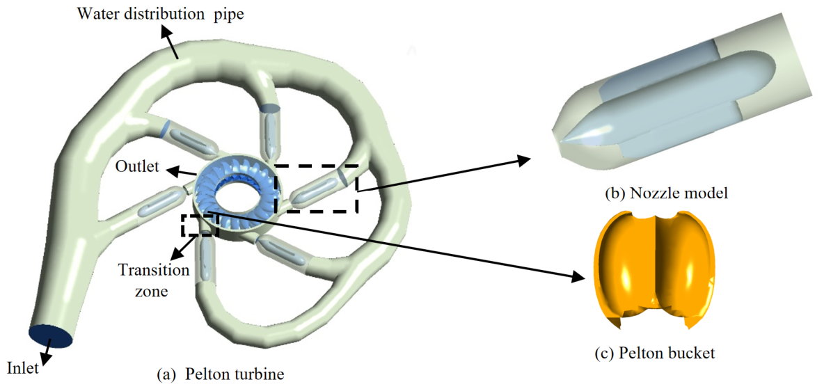
The research object of this paper is the Pelton turbine of a hydropower station. The main parameters are shown in Table 1. The main components include the water distribution pipe, nozzle, transition zone, buckets, etc. The number of buckets is 21, the number of nozzles is 6, and its three-dimensional model is shown in Figure 1.
In the present work, the computational domain includes the main distributor passage, the nozzle–needle assembly, the downstream transition region, and the bucket passage, so that the opening-dependent evolution of the internal flow, sediment transport, and wall response can be analyzed in an integrated manner. The needle opening directly controls the effective flow area of the nozzle outlet and thus determines the contraction, acceleration, and coherence of the sediment-laden jet before it impinges on the bucket surface. In this study, the term runner refers to the rotating wheel of the Pelton turbine carrying the buckets and receiving the jet impact for energy conversion. For the subsequent wall-based analysis, each bucket is further divided into the pressure side and suction side, which experience different near-wall flow structures and particle impact characteristics after jet impingement. Therefore, a clear description of the needle, jet, and bucket geometry is essential for understanding the coupling among opening regulation, jet development, wall shear distribution, entropy production, and erosion behavior.

2.2.2. Mesh Delineation and Mesh Independence Study

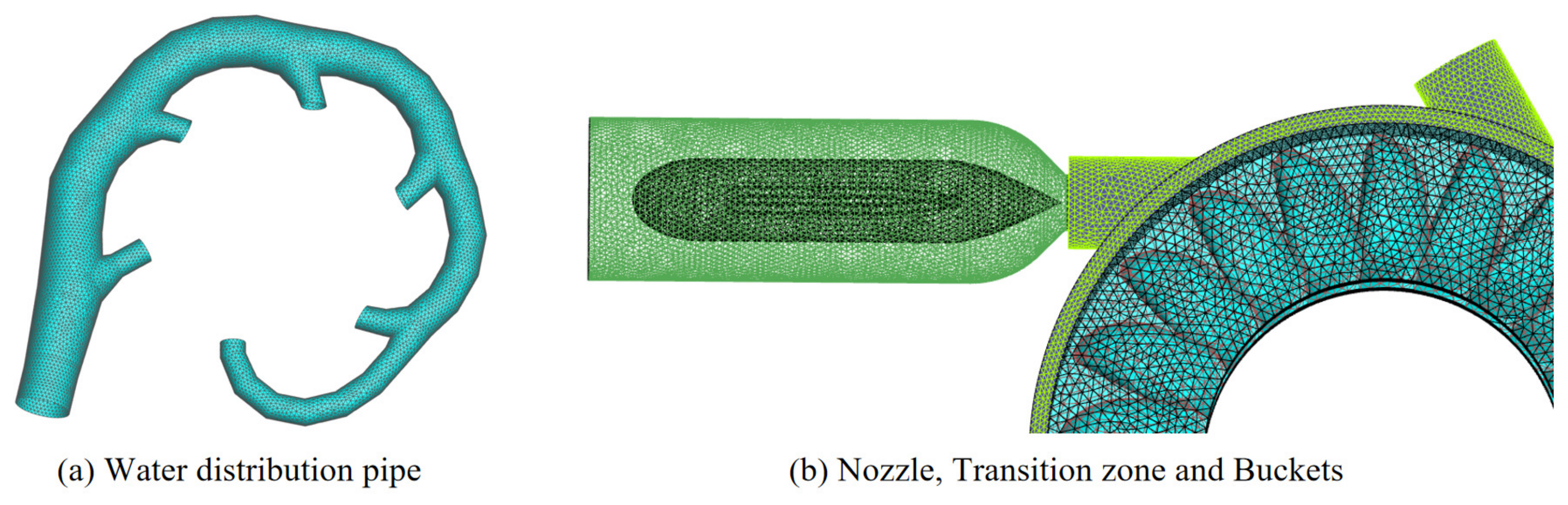
Considering the geometric complexity of the Pelton turbine, the computational domain is discretized using a hybrid meshing strategy, as shown in Figure 2. To accommodate the large geometric variation in the needle opening region and the complex shapes of the nozzle, transition zone, and buckets, unstructured meshes are employed in these regions. In addition, local mesh refinement is applied near the needle tip and contraction region, along the bucket pressure and suction surfaces, and in the jet impingement and turning zones. These regions are characterized by strong flow acceleration, large near-wall velocity gradients, and intense particle–wall interactions, and therefore require enhanced near-wall resolution for the present erosion and entropy production analyses.
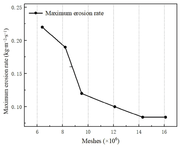
Mesh resolution influences both numerical accuracy and computational cost; therefore, a grid-independence assessment is performed using the maximum erosion rate as the monitoring metric. As shown in Figure 3, refining the mesh leads to a pronounced reduction in the predicted maximum erosion rate of the nozzle–needle (injection) assembly at low grid counts, whereas further refinement results in only minor variations once the mesh size exceeds approximately 1.4 × 10⁷ cells, indicating that the solution has essentially converged. Balancing accuracy and efficiency, a total of 14.3 million cells are adopted for the full-passage simulation, of which 7.4 million cells are allocated to the nozzle–needle assembly.
Since the monitored quantity is the maximum erosion rate, which is directly controlled by near-wall particle impact behavior and local wall gradient resolution, the grid-independence result also provides practical support for the reliability of the wall region discretization used in the present erosion and entropy production analyses.

2.2.3. Boundary Conditions and Calculation Parameters

(a)
Boundary condition
Water is treated as an incompressible fluid. A pressure condition is prescribed at the distributor manifold, while the downstream boundary is specified as a pressure outlet with a reference relative pressure of 0 Pa. All stationary components (e.g., the manifold and nozzle casing) are modeled as smooth, no-slip walls. The Pelton runner surface is defined as a rotating wall, with the remaining walls kept stationary. Therefore, the jet development and contraction in the nozzle–runner interaction zone are determined by the internal pressure-driven flow solution rather than constrained by a prescribed outlet velocity. In addition, the same downstream pressure boundary is applied consistently to all three opening conditions so the reported differences in jet development, entropy production, and erosion behavior reflect opening-dependent flow responses under a unified boundary condition framework. For particle–wall interaction, a rebound coefficient of 1.0 is adopted for sand impacts, meaning that the post-impact particle motion is treated using a rebound-type wall interaction rather than particle trapping at the wall. The rotor–stator coupling between the jet domain and the runner domain is handled using the frozen rotor approach, i.e., a steady rotor–stator interface treatment in which the relative circumferential position between the rotating and stationary domains is fixed during data transfer. During the simulations, the high-resolution discretization is applied to the convection terms and the turbulence equations. For the particle phase, the solid particles are treated as sediment (sand) particles with a density of 2300 kg/m3, and the particle mass flow rate is set to 2 kg/s.
(b)
Calculation parameters
In this study, the needle opening is adopted as the primary operating parameter to quantify its effects on hydraulic energy dissipation and wear characteristics in a Pelton turbine. Three representative needle openings—20%, 40%, and 54%—are examined, as defined by the relative needle stroke. These settings cover a typical range of operating conditions, enabling a systematic assessment of how variations in the nozzle effective area and jet development modify the internal flow structure and the associated energy loss behavior.

2.3. Entropy Production Theory

Entropy generation is a thermodynamic signature of irreversibility, representing the portion of hydraulic mechanical energy that is unavoidably degraded into internal energy during flow. In a Pelton impulse turbine, the water undergoes strong acceleration and turning within the nozzle–needle regulating device and then forms a high-velocity jet, where intense velocity gradients, turbulent mixing, and possible local separation produce additional hydraulic losses. These loss mechanisms can be quantified in a unified manner through the entropy generation rate, which is defined as follows:
S ˙ D = Q ˙ T
where S ˙ D represents the direct entropy production rate, KW/(m3·K). Q ˙ represents the energy dissipation rate, W/m3. T represents the system temperature, K.
Following Bejan’s entropy generation framework [39] for transport processes, the irreversible losses in a turbulent flow field can be decomposed into two contributions: (i) entropy production associated with the mean (time-averaged) velocity gradients, and (ii) entropy production caused by turbulent dissipation linked to velocity fluctuations. For the strongly accelerated and highly turbulent jet-forming flow in the Pelton impulse turbine nozzle–needle system, this decomposition enables a clearer identification of where the dominant loss mechanisms originate (mean shear versus turbulent mixing). Accordingly, the local entropy generation rates due to the mean motion, S ˙ D ¯ , and due to fluctuating motion, S ˙ D , are written as follows:
S ˙ D ¯ = 2 μ T u ¯ x 2 + v ¯ x 2 + w ¯ x 2 + μ T u ¯ y + v ¯ x 2 + u ¯ z + w ¯ x 2 + μ T v ¯ z + w ¯ y 2
S ˙ D = 2 μ e f f T u x 2 + v y 2 + w z 2 + μ e f f T u y + v x 2 + u z + w x 2 + μ e f f T v z + w y 2
μ e f f = μ + μ t
where S ˙ D ¯ is the entropy production rate computed from the average velocity, KW/(m3·K).  S ˙ D is the entropy production rate computed from the pulsation velocity, KW/(m3·K).  μ e f f is the effective viscosity, including both molecular and turbulence-induced momentum transport contributions, Pa·s. μ is the dynamic viscosity of water, Pa·s. u ¯ , v ¯ , and w ¯ are the components of the time-averaged velocity in different directions. u , v , and w are the components of the pulsation velocity in different directions, m/s. T is temperature, K. It should be noted that the term ‘pulsation’ in the present study does not refer to an externally imposed pulsatile inflow or a periodic needle motion condition. Instead, it denotes the fluctuation-related part of the flow field in the entropy production decomposition, i.e., the irreversible dissipation associated with velocity fluctuations represented within the adopted turbulence model framework.
In a Pelton impulse turbine, the needle–nozzle regulation forms a high-speed free jet and pronounced shear-layer turbulence upstream of the buckets. The entropy generation associated with these velocity fluctuations cannot be recovered from Reynolds-averaged variables; thus, it is estimated through a correlation based on turbulence model parameters, expressed as follows:
S ˙ D = β ρ ω k T
where β is 0.09, and ω is the turbulent vortex strength, s−1. k is the turbulent kinetic energy, m2/s2. T is temperature, K.
The total local entropy production ( S ˙ D ) is expressed as follows:
S ˙ D = S ˙ D ¯ + S ˙ D
For a Pelton impulse turbine, substantial irreversibility is also generated in near-wall regions, particularly along the nozzle–needle surfaces where the flow is strongly accelerated and in the buckets where the jet undergoes rapid turning and deceleration. To account for this wall contribution, the wall entropy production term ( S p r o , W ) can be expressed as follows:
S p r o , W = A   τ w · v T ˉ d A
where A is the area, m2. v is the velocity vector of the first layer of the mesh into the wall area, m/s. τ w is the wall shear stress, Pa. T ˉ represents the average temperature, K.
The time-averaged entropy production and the pulsating velocities entropy production in the dominant zone can be expressed as follows:
S p r o , D ¯ = V S ˙ D ¯ d V
S p r o , D = V S ˙ D d V
where S p r o , D ¯ is the sum of the entropy production rate due to direct dissipation, KW/K. S p r o , D is the sum of the entropy production rate due to turbulent dissipation, KW/K. V is volume, m3.
The total entropy production can be expressed as follows:
S p r o = S p r o , W + S p r o , D ¯ + S p r o , D
For the Pelton turbine nozzle examined in this work, full-passage CFD simulations are performed in ANSYS CFX under three needle openings (20%, 40%, and 54%) to resolve the corresponding flow fields. The entropy generation relations are subsequently implemented in the CFX Expression Language (CEL), enabling the evaluation of local entropy production rates and the integration of total entropy production over the specified regions of interest for each opening condition. The local entropy production rates are calculated from the resolved flow field and then volume-integrated (for S p r o , D ¯   and   S p r o , D ) and wall-integrated (for S p r o , W ) over each major flow component, including the water distribution pipe, nozzle, transition zone, and buckets. Figure 4 and Figure 5 present the resulting component-wise entropy production budgets in normalized form.

3. Results and Analysis

3.1. Reliability Verification

As verified by Guo [40] and others, the high-erosion area of the nozzle is located near the nozzle contraction section, and its erosion position and strength are basically consistent with the erosion position of the actual erosion results, indicating that it is feasible to predict the erosion inside the nozzle through numerical calculation.

3.2. Entropy Generation Losses of Different Components Under Different Operating Conditions

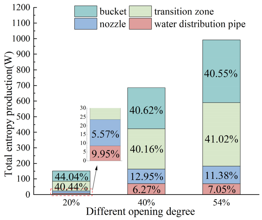
As shown in Figure 4, the entropy production rates obtained from the CFD solution are integrated over the four main flow components, i.e., the water distribution pipe, nozzle, transition zone, and buckets, and then normalized by the total entropy production of the whole flow passage. The results show that variations in nozzle opening not only markedly alter the overall level of entropy production, but also yield a relatively stable component-wise partitioning of irreversible losses. When the opening increases from 20% to 40% and 54%, the total entropy production rises substantially, indicating that larger openings enhance the jet momentum flux and promote shear-layer development and turbulent mixing, thereby accelerating the accumulation of irreversible losses. In terms of component contributions, the transition zone and the buckets consistently dominate the dissipation budget. At 20% opening, the transition zone and buckets contribute 40.44% and 44.04%, respectively (84.48% in total). At 40% opening, their contributions are 40.16% and 40.62% (80.78% in total). At 54% opening, they account for 41.02% and 40.55% (81.57% in total). These results confirm that irreversibility remains concentrated in the highly unsteady region surrounding the nozzle–bucket interaction. Jet diffusion and intense shear-driven mixing in the transition zone, together with impingement, separation, and near-wall friction within the buckets, constitute the primary sources of entropy production. By comparison, the upstream components contribute less overall but exhibit greater sensitivity to opening variation. The share of the water distribution pipe decreases from 9.95% to 6.27% and then rebounds to 7.05% at 54%, whereas the nozzle contribution increases from 5.57% to 12.95% and subsequently decreases slightly to 11.38% at 54%. This behavior suggests that throttling at small openings makes upstream frictional losses relatively more prominent, while, at moderate-to-large openings, stronger in-nozzle acceleration and shear-layer activity elevate the nozzle’s dissipation share. Nevertheless, the dominant dissipation region does not shift upstream and continues to be governed primarily by the transition zone and bucket region. These component-scale results mainly describe the fluid-side irreversibility budget; however, their engineering significance becomes clearer when combined with the opening-dependent particle redistribution discussed in Section 3.3. In particular, the increase in entropy production within the transition zone and bucket region is consistent with the stronger particle non-uniformity, near-wall enrichment, and subsequent impact-driven erosion observed under different openings, indicating that the fluid dissipation field provides the hydrodynamic background upon which particle-induced wear develops.
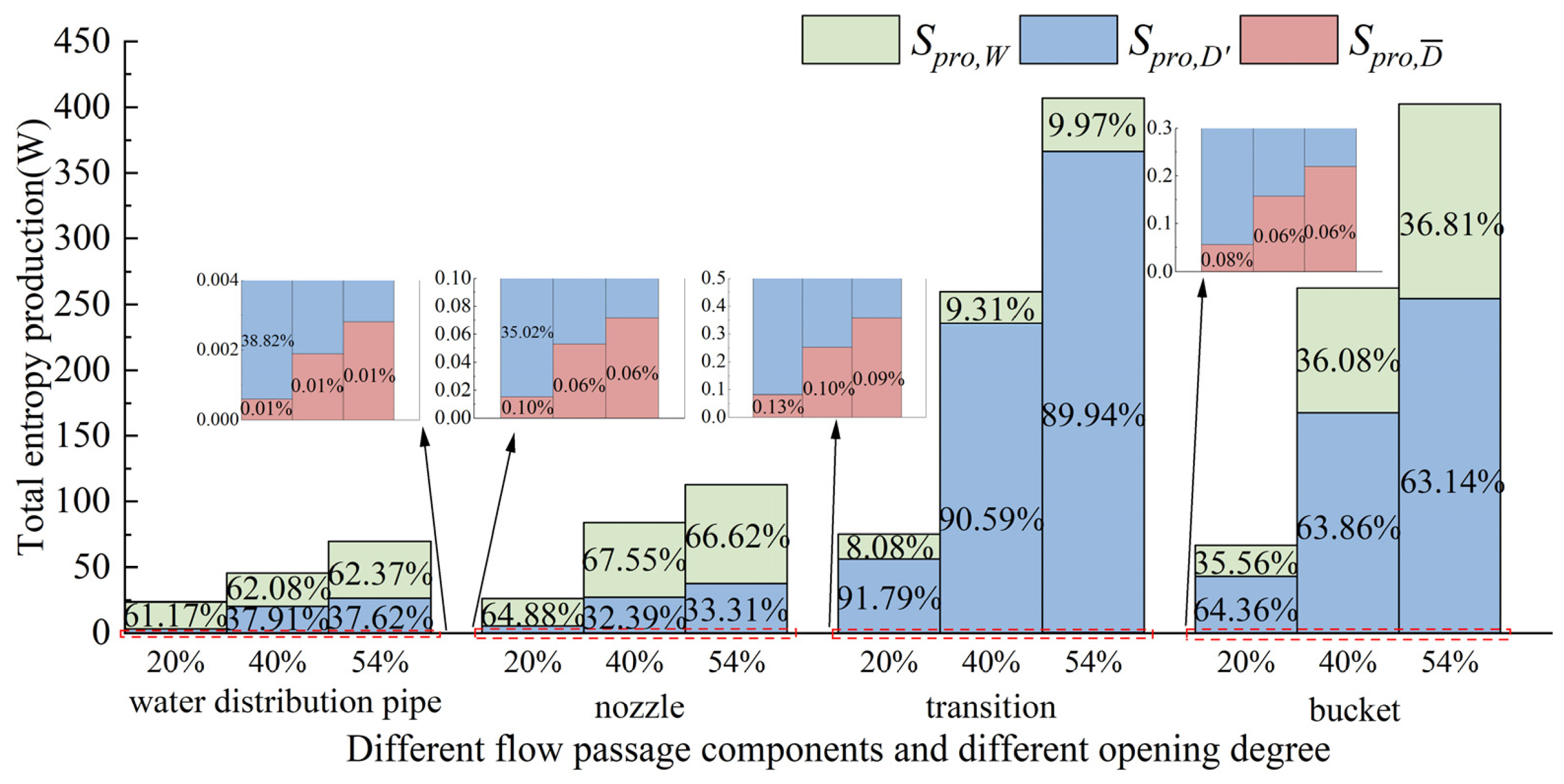
As shown in Figure 5, the entropy production under the three nozzle opening conditions exhibits a pronounced spatial partitioning among the different components, while the relative contributions of the three entropy production terms ( S p r o , D ¯ , S p r o , D , and S p r o , W ) remain broadly consistent across operating conditions. Overall, as the nozzle opening increases from 20% to 40% and 54%, the entropy production rises in all components, with the most substantial growth observed in the transition zone and the buckets. In the large-opening cases, the entropy production in these two regions is markedly higher than that in the water distribution pipe and nozzle, indicating that the dominant irreversibility is concentrated in the highly unsteady flow zones around the nozzle–bucket interaction rather than in the upstream water distribution pipeline and the nozzle body itself. The decomposition further reveals distinct component-dependent mechanisms. Both the water distribution pipe and nozzle are dominated by the wall entropy production S p r o , W ( S p r o , W accounts for approximately 62–67%, with S p r o , D contributing 33–38%), suggesting that losses in the upstream conduit and within the nozzle are primarily governed by near-wall shear and frictional dissipation. Moreover, the S p r o , D / S p r o , W split remains nearly unchanged between the 40% and 54% openings, implying that varying the opening has a limited impact on the composition of dissipation mechanisms in these regions and mainly manifests as a proportional increase in the overall entropy production level. In contrast, the transition zone is clearly dominated by the direct entropy production S p r o , D ( S p r o , D decreases slightly from 91.79% to 90.59% and 89.94%, while S p r o , W remains around 8–10% and increases mildly with opening). This pattern indicates that irreversibility in the transition section is primarily associated with volumetric dissipation processes such as intense shear-layer mixing and turbulence dissipation during jet development. The modest rise in the S p r o , W fraction further suggests that, at larger openings, strengthened near-wall velocity gradients enhance the relative importance of wall friction losses. For the buckets, the entropy production budget exhibits a characteristic balance between volumetric and wall dissipation. As the nozzle opening increases from 20% to 40% and then to 54%, the contribution of S p r o , D decreases slightly from approximately 64.36% to 63.86%, and further to 63.14%, whereas the share of S p r o , W increases modestly from about 35.56% to 36.08% and then to 36.81%. This implies that the buckets experience both strong volumetric dissipation induced by jet impingement, separation, and recirculation and pronounced frictional dissipation associated with near-wall sliding and reattachment on the bucket surfaces. The slight increase in S p r o , W when opening further indicates that a higher incident momentum flux tends to intensify surface shear and frictional losses on the buckets. It is worth emphasizing that the indirect entropy production S p r o , D ¯ remains negligibly small in all components across the three openings (discernible only in the magnified inset) and can therefore be reasonably neglected in the discussion of the energy loss budget. Taken together, the figure quantitatively demonstrates that increasing the opening further concentrates the major contribution of irreversibility in the transition zone and the buckets region and yields a relatively stable mechanistic pattern. Dissipation in the transition section is dominated by S p r o , D . Dissipation in the upstream components is dominated by S p r o , W . The bucket exhibits combined contributions from S p r o , D and S p r o , W .
These component-scale results mainly describe the fluid-side irreversibility budget; however, their engineering significance becomes clearer when combined with the opening-dependent particle redistribution discussed in Section 3.3. In particular, the increase in entropy production within the transition zone and bucket region is consistent with the stronger particle non-uniformity, near-wall enrichment, and subsequent impact-driven erosion observed under different openings, indicating that the fluid dissipation field provides the hydrodynamic background upon which particle-induced wear develops.

3.3. Evolution of Velocity and Sediment Distribution Along the Nozzle Under Varying Openings

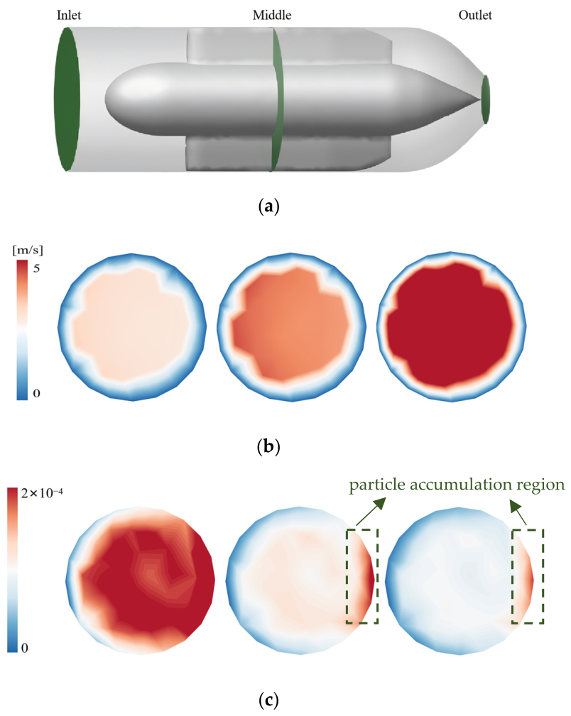
From the nozzle inlet section (Figure 6), it is evident that the nozzle opening substantially modulates both the uniformity of the inlet velocity field and the lateral redistribution of sediment particles by altering the contraction intensity of the passage and the near-wall shear structure. In terms of velocity, the 20% opening exhibits an overall lower speed level accompanied by a pronounced low-velocity annulus near the outer periphery, indicating an increased relative contribution of the boundary layer and enhanced radial momentum dissipation and diffusion at the inlet. As the opening increases to 40% and 54%, the high-velocity region expands markedly and becomes more uniform, with improved circumferential consistency. This suggests that a larger opening enables more effective acceleration of the core flow, mitigates inlet velocity distortion, and thereby provides a more stable inflow condition. In contrast, the particle volume fraction responds more sensitively to the opening variation. At 20% opening, a distinct high-concentration zone with strong non-uniformity is observed, implying that intensified throttling promotes near-wall shear and secondary-flow structures that drive inertial migration and local particle clustering, leading to pronounced lateral segregation immediately after entering the nozzle. At 40% and 54% openings, the particle volume fraction decreases substantially and becomes comparatively homogeneous, with only weak enrichment persisting near localized edges. This indicates that the strengthened convective transport and shortened residence time suppress the segregation–clustering tendency, allowing particles to be conveyed more uniformly with the carrier flow. Overall, the inlet section reveals a trend that is critical for the subsequent evolution of erosion and entropy production: smaller openings tend to promote a coupled state characterized by a peripheral low-velocity band and particle enrichment, which increases the likelihood of particle–wall relative impact.
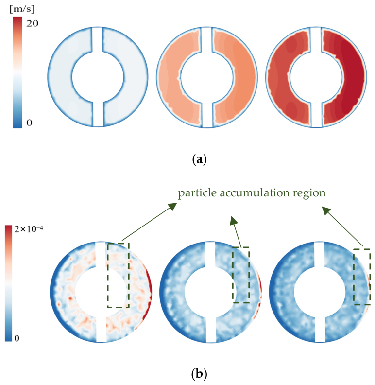
For the nozzle mid-section (Figure 7), this location—compared with the inlet section—more clearly captures the evolved behavior of the sediment–water mixture under the combined effects of contraction-driven acceleration, near-wall shear, and secondary flow-induced redistribution. In the 20% opening case, the annular passage remains in a relatively weak acceleration regime; the circumferential momentum of the core flow is perturbed by structural ribs/narrow-gap regions, giving rise to localized velocity non-uniformity and noticeable asymmetry. As the opening increases to 40% and 54%, a more continuous high-velocity core develops and the high-speed band extends along the annulus, indicating a more effective acceleration process in the mid-section and an increased dominance of convective transport. Nevertheless, relatively low-speed/high-gradient strips remain discernible in the vicinity of the ribs. Such regions with a concentrated velocity gradient typically correspond to intensified near-wall shear and frictional dissipation, and therefore represent plausible sources for elevated wall entropy production. Compared with the velocity field, the particle volume fraction distribution provides a more direct indication of opening-dependent sediment redistribution and potential near-wall particle accessibility. At 20% opening, the section exhibits pronounced patchy fluctuations accompanied by a near-wall enrichment band on one side, suggesting that, under small-opening conditions, secondary flows and shear layers more readily induce lateral sorting and clustering. Consequently, particles traverse the mid-passage in the form of localized clusters superimposed on a biased enrichment strip. In contrast, at 40% and 54% openings, the overall particle volume fraction decreases markedly and becomes a weak-gradient field, with only narrow near-wall enrichment traces persisting locally. This implies that, as the opening increases and the main-flow convection strengthens, particle residence time and recirculation trapping are reduced, so sediment transport approaches an enhanced flow-following regime—although a residual tendency for near-wall preferential accumulation remains due to shear/secondary-flow effects.
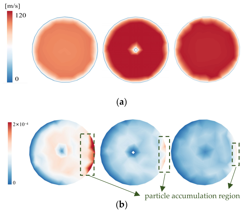
For the nozzle outlet section (Figure 8), the flow nearly reaches its final jet formation state and thus defines the effective inlet boundary condition for the bucket. The velocity and particle distributions at this plane not only encapsulate the cumulative effects developed within the nozzle, but also directly govern the impingement intensity on the bucket and the uniformity of sediment-laden inflow. Compared with Figure 4 (inlet) and Figure 5 (mid-section), a salient feature in Figure 6 is that, at the larger openings of 40% and 54%, the velocity field exhibits a more distinct “high near-axis, low near-periphery” pattern, with a more stable high-speed core and improved circumferential continuity. This indicates that, after the acceleration and partial flow conditioning in the mid-section, the jet momentum becomes more concentrated at the outlet, yielding a relatively mature jet core. In contrast, the 20% opening case still retains pronounced velocity distortion and non-uniformity at the outlet, implying that throttle-induced shear-layer disturbances and localized recirculation can persist downstream and deteriorate jet quality, in terms of both velocity coherence and core stability. More importantly, the particle distribution at the outlet displays a trend different from that observed in Figure 5. While the particle volume fraction in the inlet and mid-section (Figure 4 and Figure 5) is more readily modulated into patchy fluctuations or localized streaks by secondary-flow effects, the outlet plane features an overall lower particle volume fraction with a clearer edge-biased pattern: narrow enrichment bands emerge near the outer periphery at certain circumferential locations, whereas the core region appears relatively diluted. This suggests a progressive redistribution process within the nozzle, transitioning from cross-sectional fluctuations and clustering/bias (more evident upstream) toward preferential migration along the jet shear layer/periphery as the jet core becomes established. Once the jet core stabilizes, particles are more prone to be entrained by the outer shear layer and experience centrifugal/inertial drift, thereby accumulating toward the periphery and forming localized enrichment bands. The influence of the nozzle opening on this process is twofold. On the one hand, increasing the opening (40% → 54%) strengthens and streamlines the outlet jet core, implying a higher mean incident momentum flux delivered to the bucket. On the other hand, the outlet particle field becomes more uniform overall and the mean concentration decreases, with only limited residual enrichment persisting near the periphery.

3.4. The Coupling Relationship Between Wall Erosion and Entropy Generation at Different Opening Degrees

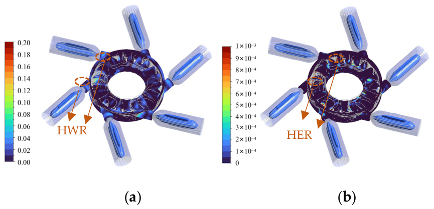
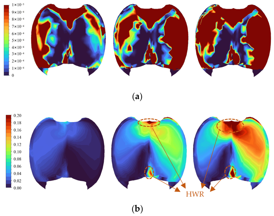
By jointly examining the wall erosion rate density and wall entropy production distributions across the three nozzle opening conditions, a clear overall coupling between the two fields can be identified, with the coupling strength and spatial manifestation evolving markedly with opening. To facilitate comparison, the erosion rate density (ERD) and wall entropy production rate ( S p r o , W ) are nondimensionalized, and the corresponding formulations are given in Equations (17) and (18). Under the small-opening condition (Figure 9), the jet contracts and its effective footprint becomes more confined. The high-entropy-production regions typically appear as localized bands, primarily aligned with high-shear zones induced by post-impingement wall-attached sliding and local reattachment. In contrast, erosion hotspots are more discrete and usually occur as speckles or short streaks near curvature discontinuities, alternating separation–reattachment locations, and abrupt turning of the local flow direction. This indicates that, at small openings, wear is more readily governed by the amplification of local nonlinear factors, including particle accessibility and impact kinematics, resulting in a more intermittent and peak-dominated erosion response relative to the entropy production background.
  E R D D = E R D E R D m a x
  W E P D = S p r o , W S p r o , W , m a x
where E R D   and S p r o , W represent the erosion rate density (ERD) and wall entropy production (WEP) rate in the computational domain, respectively. ERDmax and   S p r o , W , m a x represent the maximum values of ERD and WEP in the computational domain, respectively. ERDD and WEPD represent the dimensionless values of ERD and WEP, respectively.
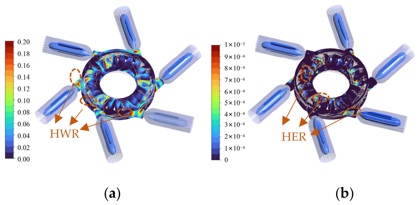
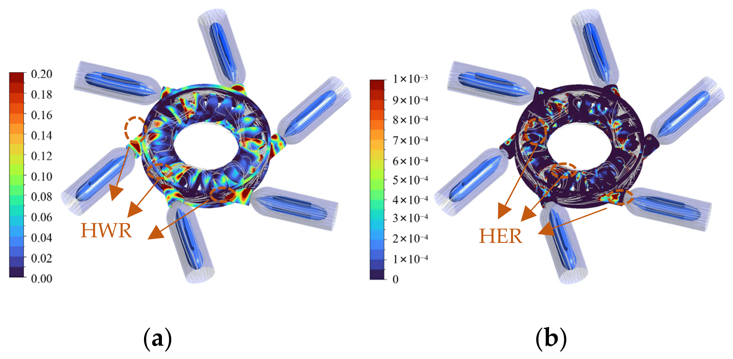
As the opening increases to the medium level (Figure 10), the jet momentum flux and coverage expand. High-entropy-production bands become more continuous and extend along the primary turning pathway on the inner bucket wall, enabling high-shear dissipation zones to form spatially connected structures. Correspondingly, erosion hotspots, while still concentrated near the transition zone and buckets, occur more frequently within the internal turning and reattachment regions of the buckets and exhibit a more evident spatial co-location with the high-entropy-production bands. This shift suggests that the coupled mechanism of near-wall shear dissipation, particle wall-attached transport with local enrichment, and tangential abrasive erosion becomes increasingly dominant, thereby strengthening the spatial consistency between wear and entropy production compared with the small-opening case. Under the large-opening condition (Figure 11), the high-entropy-production regions generally develop into circumferentially more continuous bands with substantially larger coverage, and stronger connectivity is observed near the outer edge of the impingement sector and along the inner-wall turning passage of the buckets. This behavior reflects a pronounced intensification of irreversible dissipation driven by near-wall friction and shear. Meanwhile, erosion rate density hotspots tend to cluster along the impingement belt, at geometric discontinuities, and near reattachment boundaries, where higher local peaks are more likely to occur. The elevated entropy production, associated with higher wall shear stress and stronger turbulent redistribution, promotes increased near-wall particle flux and longer near-wall residence, thereby raising the probability of erosion events.
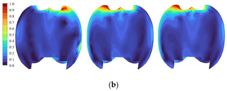
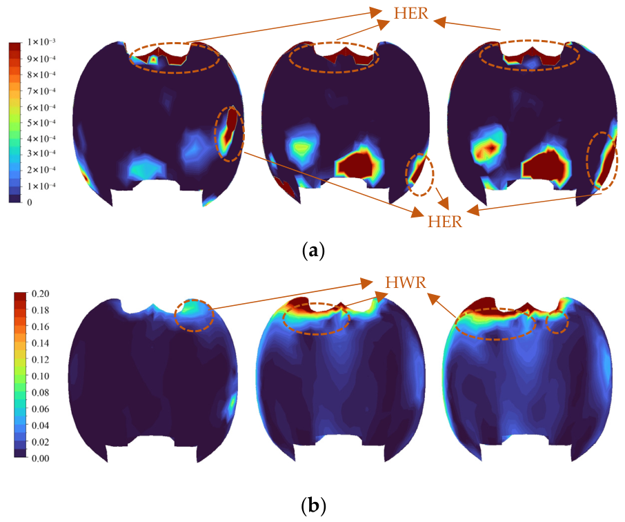
As shown in Figure 12, the wall erosion rate density and the wall entropy production rate exhibit a clear background–trigger type coupling in their spatial distributions, and this coupling becomes noticeably stronger as the opening increases. At the 20% opening, high erosion rate density values are mainly organized as continuous or semi-continuous bands along the bucket outer rim accompanied by localized streak-like and patch-like hotspots inside the bucket. In contrast, the wall entropy production rate remains relatively low overall and shows a comparatively mild spatial gradient. This indicates that, under the small-opening condition, wear is more readily triggered by localized particle impingement and geometric discontinuities, leading to relatively discrete erosion hotspots with limited dependence on the frictional dissipation background. When the opening increases to 40%, the wall entropy production rate develops more distinct high-value regions near the impingement area and along one side of the inner wall, and further extends downstream into a directional high-value band. This reflects the enhanced jet momentum flux, which strengthens near-wall shear and makes frictional dissipation pathways more pronounced. Correspondingly, erosion hotspots occur more frequently, not only along the outer lip but also in the reattachment regions adjacent to the high-entropy-production band, resulting in a more evident spatial co-location between the two fields. This evolution suggests that a coupled mechanism involving high shear, wall-attached particle transport, and tangential abrasive erosion becomes increasingly dominant. At the 54% opening, the high-entropy-production region expands further and exhibits stronger connectivity and circumferential asymmetry, indicating a pronounced intensification of near-wall irreversibility driven by friction and shear. High erosion rate density values still preferentially cluster within the impingement belt and near geometric edges, while stronger local peaks appear in regions overlapping with, or immediately adjacent to, the high-entropy-production band, forming a characteristic pattern of a strong dissipation background with locally amplified peaks.
As shown in Figure 13, the erosion rate density and the wall entropy production rate exhibit a discernible spatial association, yet their coupling pattern differs markedly from that on the pressure side. Overall, the suction-side behavior is characterized by a weak dissipation background with discrete erosion triggering. At the 20% opening, the wall entropy production rate on the suction side remains low overall, with only a narrow band of weakly elevated values near the impingement lip, indicating relatively limited near-wall shear and frictional losses on this side. Accordingly, the erosion rate density is dominated by a few discrete patches, with hotspots typically located at local geometric discontinuities (e.g., edges, local turning features, or reattachment-prone regions), and no coherent erosion band develops along the flow direction. This suggests that, under the small-opening condition, suction-side wear depends primarily on intermittent particle accessibility and localized impact events rather than being governed by a sustained high-friction dissipation pathway. When the opening increases to 40%, the wall entropy production rate near the lip strengthens significantly and expands into a more continuous high-value band, reflecting intensified shear-layer activity and larger near-wall velocity gradients induced by the higher incident momentum, which makes the frictional dissipation pathway more pronounced. Nevertheless, erosion hotspots remain dominated by discrete peaks, mainly distributed near the lower rim and local lateral edges. Their spatial relationship with the high-entropy-production band is often adjacent but not fully overlapping, implying that suction-side erosion is more likely triggered by mechanisms such as re-impingement after particle rebound, cross-stream transport by secondary flows, and local trapping by recirculation, rather than scaling directly with wall friction intensity. At the 54% opening, the lip-region wall entropy production rate increases further and the high-value band becomes more continuous, indicating a pronounced enhancement of near-wall irreversibility. Meanwhile, both the number and intensity of erosion hotspots increase, and more evident co-location or near-adjacency emerges in parts of the edges and locally elevated entropy production regions. The erosion field, however, remains patchy and peak-dominated overall. This behavior indicates that a stronger high-friction background at a large opening can increase near-wall particle flux.
Overall, Figure 13 shows that the wear–dissipation coupling on the suction side is more indirect than that on the pressure side. The wall entropy production rate primarily delineates potential high-risk regions associated with near-wall shear and frictional losses, whereas the erosion rate density is more sensitive to the nonlinear amplification associated with particle kinematics and re-impingement processes. As the opening increases, the high-entropy-production band evolves from being weak and localized to stronger and more continuous, increasing the proximity and likelihood of co-location between erosion hotspots and high-dissipation regions, although a strict one-to-one morphological correspondence remains unlikely.

3.5. Role of Wall Shear Stress in the Opening-Dependent WEP–ERD Correlation

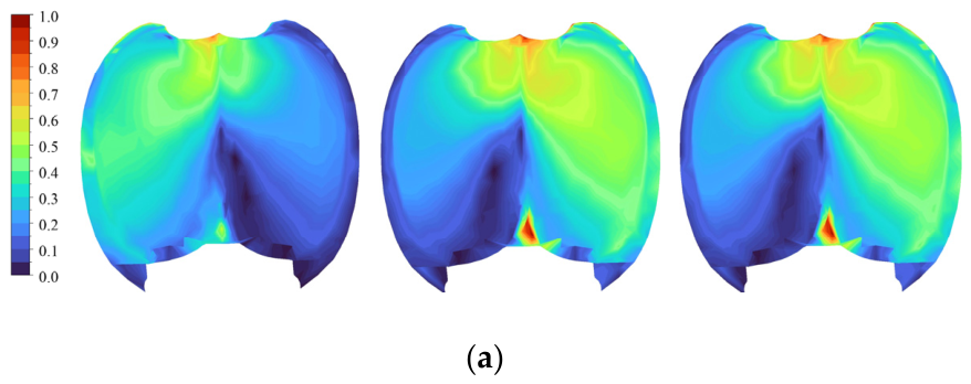
To further clarify why the spatial correlation between wall entropy production (WEP) and erosion rate density (ERD) becomes more evident with increased nozzle opening, the wall shear stress distribution on both the pressure and suction sides of the bucket is additionally examined, as shown in Figure 14. The wall entropy production is directly determined by the wall shear stress and the near-wall velocity of the first mesh layer. Therefore, from a boundary-layer perspective, WEP is not merely a qualitative indicator of dissipation, but a direct measure of the irreversible loss associated with near-wall shear transport. In this sense, the wall shear field provides a physical bridge between the hydraulic dissipation pattern and the particle-induced wear pattern. For consistency of comparison among different opening conditions, the wall shear stress is further presented in dimensionless form, and the corresponding normalization is defined as follows:
  W S S D   = W S S W S S m a x
where WSS represents the wall shear stress on the wall surface. WSSmax represents the maximum values of wall shear stress on the wall surface. WSSD represents the dimensionless values of WSS.
On the pressure side (Figure 14a), the wall shear distribution exhibits a clear opening dependence. At the 20% opening, the wall shear level is relatively weak and its high-value regions are less organized, indicating that the near-wall momentum transfer remains limited and that the friction dissipation background is still weak. Under this condition, the erosion field is mainly controlled by localized particle impingement, geometric discontinuities, and intermittent impact accessibility, so the ERD pattern appears as discrete or semi-continuous hotspots with limited correspondence to the WEP field. As the opening increases to 40% and 54%, the incoming jet becomes more coherent and maintains a stronger high-momentum core, which promotes a more stable wall-attached flow after bucket impingement. Meanwhile, the higher incident momentum strengthens the near-wall tangential velocity gradient and intensifies the wall shear, especially in the impingement belt and downstream reattachment regions, forming a more continuous high-shear pathway on the pressure side. Because WEP is directly proportional to the wall shear stress, this redistribution of wall shear explains the evolution of the WEP field from weak localized patches to connected high-value bands. Under the same conditions, particles are more likely to follow the near-wall flow path and interact with the wall in a grazing manner, so tangential abrasive erosion develops preferentially along the same high-shear route. As a result, the co-location or near-adjacency between ERD hotspots and WEP bands becomes much more evident at larger openings.
From the viewpoint of boundary-layer theory, the wall shear stress is governed by the near-wall velocity gradient, and thus reflects the intensity of momentum exchange within the wall-bounded layer. At larger openings, the stronger and more coherent jet not only reduces random cross-stream particle dispersion upstream, but also enhances the near-wall velocity gradient after impingement and reattachment on the bucket surface. Consequently, the near-wall layer becomes a preferential pathway for both frictional dissipation and particle transport. In other words, jet coherence acts mainly as an upstream conditioning factor that stabilizes particle delivery, whereas the redistribution of wall shear stress is the more direct surface-scale mechanism that determines where high-WEP regions form and why ERD tends to align with them.
The wall shear distribution on the suction side (Figure 14b) shows a different behavior. Although the wall shear stress near the lip region also increases with opening and the corresponding WEP band becomes more continuous, the ERD field remains more patchy and peak-dominated. This indicates that suction-side wear is not governed solely by the local wall friction intensity. Instead, particle rebound, secondary flow-induced cross-stream transport, and local recirculation/trapping still play important roles in determining where erosion hotspots appear. Therefore, the WEP–ERD coupling on the suction side remains more indirect, whereas, on the pressure side, the coupling becomes progressively stronger because the increase in opening simultaneously enhances wall-bounded shear transport and grazing particle delivery.

3.6. The Opening-Dependent Coupling Between Particle Incidence Characteristics and Impact Kinematics

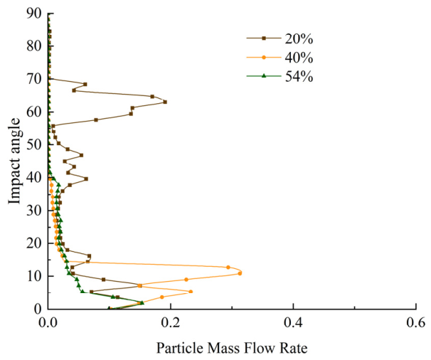
Figure 15 presents the joint distribution of particle mass flow rate versus impact angle for three nozzle openings (20%, 40%, and 54%), which is used here to characterize the opening-dependent incidence regime and, indirectly, the associated wall impact momentum tendency. For all cases, particles impacting at moderate-to-large angles (α > 30°) generally carry negligible mass flow rate, with most data points clustered near the abscissa origin, indicating that high-angle impacts are sporadic and contribute little to the overall particle throughput. In contrast, the primary mass contribution is concentrated at low impact angles α ∈ (0–15°). Among the three conditions, the 40% opening exhibits the most pronounced low-angle concentration, where the mass flow rate peaks within a narrow band of α ∈ (5–13°) and extends to the highest levels observed in the dataset, implying a strongly grazing incidence-dominated particle delivery. The 54% opening also remains governed by low-angle impacts (α ∈ (0–10°)), but with a reduced mass flow envelope compared with 40%, suggesting a more streamlined jet and enhanced particle flow-following behavior that suppresses events with appreciable normal incidence. By contrast, the 20% opening shows a markedly broader angular spread: in addition to the low-angle branch, a distinct population emerges at higher impact angles (α ∈ (40–70°) with non-negligible mass flow rate, evidencing intensified jet contraction and shear layer-induced particle redistribution at small openings. Overall, increasing the nozzle opening drives the particle incidence toward a more concentrated, grazing impact regime, whereas a small opening promotes wider angle incidence with an elevated likelihood of locally strengthened normal impact events, which is consistent with an increased propensity for erosion hotspots. It should be noted that the particle mass flow rate shown here describes the angular distribution of particle throughput, whereas the actual impact severity depends jointly on the impact angle and particle velocity; therefore, wall impact momentum should be interpreted from the combined mass flow and velocity statistics rather than from mass flow rate alone.
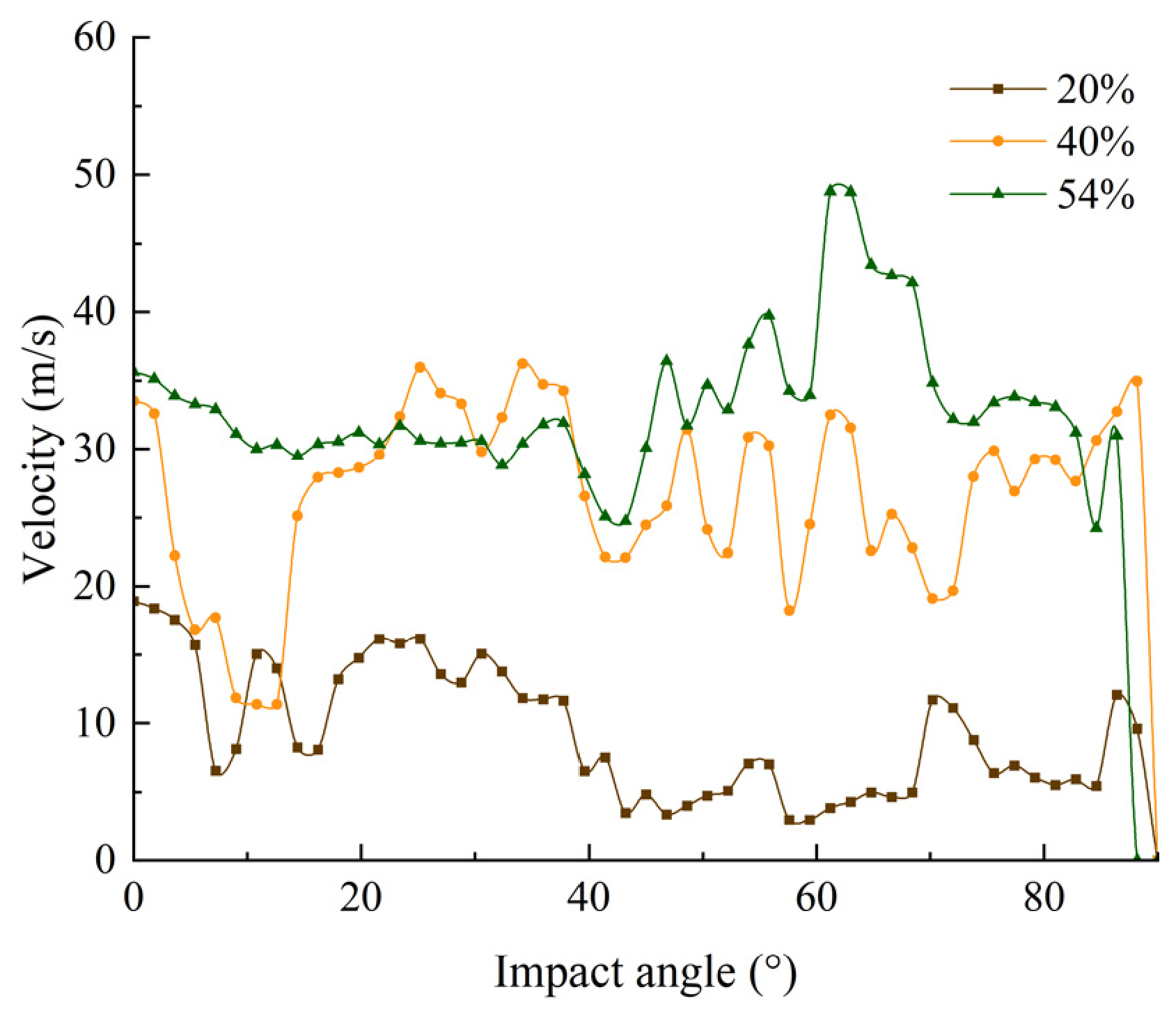
Figure 16 depicts the variation of particle velocity magnitude with impact angle for three nozzle openings (20%, 40%, and 54%). A pronounced opening dependence is evident: enlarging the nozzle opening consistently increases particle velocity across nearly the full range of impact angles. At 20% opening, particle velocities are relatively low and narrowly distributed (generally <20 m/s), with a clear minimum in the mid-angle range (α ∈ (40–60°)), suggesting substantial momentum dissipation prior to impact. At 40% opening, velocities rise to an intermediate level (typically 20–35 m/s) but display more pronounced angle-dependent variability; a distinct low-velocity trough occurs at small angles (α ∈ (10–15°)), followed by oscillatory behavior as the impact angle increases. In contrast, the 54% opening maintains consistently higher velocity (from 30 m/s to 50 m/s) and exhibits a marked acceleration in the moderate angle interval, reaching a peak of nearly 50 m/s around α ∈ (60–65°). The sustained high-velocity impacts at moderate-to-large angles under 54% opening imply greater incident kinetic energy and larger normal momentum components, thereby increasing the potential for severe erosion on exposed hydraulic surfaces. Collectively, these results indicate that larger nozzle openings favor a high-velocity impact regime over a broader incidence angle spectrum, whereas smaller openings are dominated by low-velocity impacts with comparatively limited erosive capacity.

4. Conclusions

In this paper, the numerical method can reproduce the area where the nozzle contraction section is prone to erosion, and the results are consistent with the erosion patterns that have been reported or observed. The main conclusions are as follows:
(1)
The Needle opening does not merely change the magnitude of hydraulic loss; rather, it reorganizes the impulse jet formation and dissipation pathway in the Pelton turbine. Across all openings, irreversible losses remain concentrated in the nozzle–runner interaction region, especially the transition zone and buckets, indicating that the free jet impact and turning process is the dominant carrier of opening-dependent irreversibility in the present impulse turbine system.
(2)
Opening-dependent jet development controls sediment transport patterns along the nozzle. At 20% opening, the inlet shows a pronounced peripheral low-velocity annulus accompanied by strong particle non-uniformity/clustering, whereas, at 40% and 54% openings, the velocity field becomes more uniform and the particle volume fraction decreases and homogenizes. In the mid-section, a small opening promotes patchy particle fluctuations with near-wall enrichment, while larger openings suppress trapping and shift transport toward an enhanced flow-following regime. At the outlet, larger openings yield a more stable high-speed jet core, and particles tend to exhibit a clearer edge-biased enrichment along the jet periphery.
(3)
The strengthened WEP–ERD correspondence at larger openings should be understood as a mechanism shift rather than a simple field overlap: as opening increases, improved jet coherence and intensified near-wall shear jointly promote a transition from a weak dissipation background plus discrete erosion triggering to a more organized wall-attached abrasion pathway, particularly on the bucket pressure side, whereas the suction side remains more indirectly controlled by particle re-impingement and local transport complexity.
(4)
Across all openings, particle throughput is predominantly associated with grazing impacts, while moderate-to-large impact angles contribute little to the overall mass flow. The 40% opening exhibits the most concentrated grazing incidence delivery and the largest particle throughput. The 54% opening preserves the grazing-dominated pattern but with a reduced mass flow range, whereas particle velocities remain consistently higher across the incidence spectrum, indicating increased incident kinetic energy and erosion potential. In contrast, the 20% opening is characterized by lower particle velocities but a broader distribution of impact angles, suggesting a higher likelihood of sporadic normal impact events and localized erosion hotspots.
From an engineering perspective, the opening-dependent redistribution of erosion hotspots implies a redistribution of structural risk on the bucket. At small openings, wear tends to appear as more localized and intermittent hotspots, whereas, at medium and large openings, it evolves toward more continuous wall-attached abrasive paths, especially on the bucket pressure side, where higher impact velocity and stronger near-wall shear act together. Such a shift suggests that damage may develop from isolated local erosion into persistent material thinning along impingement and reattachment-related regions. If these high-risk zones extend toward geometric transition areas or root-connected load-transfer regions, the combined effect of thickness reduction, stress concentration, and cyclic hydraulic loading may shorten fatigue life and compromise long-term structural integrity. Therefore, needle opening should be considered not only as a discharge regulation parameter, but also as an operational factor governing wear-risk redistribution, inspection priority, and maintenance planning.

Author Contributions

Conceptualization, X.S.; methodology, Y.L.; software, X.S.; validation, D.Q.; formal analysis, X.S.; investigation, X.S.; resources, L.G.; data curation, L.G.; writing—original draft preparation, D.Q.; writing—review and editing, X.S.; supervision, H.B.; funding acquisition, Z.W. All authors have read and agreed to the published version of the manuscript.

Funding

This research was supported by the National Key Research and Development Program of China (2023 YFB3408400).

Data Availability Statement

The original contributions presented in this study are included in the article. Further inquiries can be directed to the corresponding author.

Conflicts of Interest

Author Lianheng Guo was employed by the company Datang Xizang Energy Development Co., Ltd. Authors Daqing Qin and Yongxin Liu were employed by the company Harbin Electric Machinery Co., Ltd. The remaining authors declare that the research was conducted in the absence of any commercial or financial relationships that could be construed as a potential conflict of interest.

References

  1. Khan, R.; Ullah, S.; Qahtani, F.; Pao, W.; Talha, T. Experimental and numerical investigation of hydro-abrasive erosion in the Pelton turbine buckets for multiphase flow. Renew. Energy 2024, 222, 119829. [Google Scholar] [CrossRef]
  2. Tarodiya, R.; Khullar, S.; Levy, A. Particulate flow and erosion modeling of a Pelton turbine injector using CFD-DEM simulations. Powder Technol. 2022, 399, 117168. [Google Scholar] [CrossRef]
  3. Messa, G.V.; Mandelli, S.; Malavasi, S. Hydro-abrasive erosion in Pelton turbine injectors: A numerical study. Renew. Energy 2019, 130, 474–488. [Google Scholar] [CrossRef]
  4. Zhao, H.; Zhu, B.; Xu, R.; Tan, L.; Zhang, H.; Chen, L.; Liu, Z.; Yang, J.; Deng, F. Evaluating the predictive potential of modeling frameworks for Pelton turbine energy performance and guiding engineering modeling in hydroelectric applications. Energy 2025, 330, 136861. [Google Scholar] [CrossRef]
  5. Xiao, Y.; Liu, Z.; Liang, Q.; Liu, J.; Zhang, J.; Zhu, Y.; Li, X.; Gu, C. The interaction between bucket number and performance of a Pelton turbine. Energy 2024, 287, 129646. [Google Scholar] [CrossRef]
  6. Wang, X.D.; Wang, X.; Hu, S.D.; Wang, W.Q.; Yan, Y. Study on the hydrodynamic characteristics of a six-nozzle ultra-large capacity Pelton turbine during the switching of the operating nozzles. Energy 2026, 347, 140328. [Google Scholar] [CrossRef]
  7. Khan, F.; Kumar, A.; Staubli, T.; Abbas, A.; Devinar, L. Control of a pelton turbine with partial jet cutting driven by a cut-in jet deflector. Renew. Energy 2025, 239, 122063. [Google Scholar] [CrossRef]
  8. Liu, Z.; Xiao, Y.; Liang, Q.; Yang, C.; Luo, X. Effect of deflected jet on performance and cavitation characteristics of a Pelton turbine. Energy 2025, 342, 139734. [Google Scholar] [CrossRef]
  9. Semlitsch, B. Effect of inflow disturbances in Pelton turbine distributor lines on the water jet quality. Int. J. Multiph. Flow 2024, 174, 104786. [Google Scholar] [CrossRef]
  10. Wu, Y.; Zhao, H.; Zhu, B.; Xu, R.; Qin, Y.; Zhang, H.; Deng, F.; He, C.; Chen, L.; Tan, L. Flow asymmetry genesis in symmetric inlet loop pipe-nozzle systems: A mechanism for uneven power generation in Pelton turbines. Phys. Fluids 2025, 37, 085141. [Google Scholar] [CrossRef]
  11. Deng, H.; Song, K.; Deng, F.; Huang, Y.; Luo, T.; Zhou, Y.; Qin, B.; Zeng, Y.; Yu, Z.; Pang, J.; et al. Nozzle jet deviation from bucket pitch circle’s effect on the stability and efficiency of Pelton turbine. Processes 2023, 11, 1342. [Google Scholar] [CrossRef]
  12. Yuan, Z.; Liu, J.; Pang, J.; Zhang, J.; Gang, Y.; Cai, Y.; Li, J.; Wang, H.; Xu, K.; Liu, X. The Effect of Jet Deviation on the Stability of Pelton Turbine. Processes 2025, 13, 2683. [Google Scholar] [CrossRef]
  13. Khan, F.; Kumar, A.; Staubli, T. Numerical investigation of turbulent flow in Pelton turbine injector and jet quality. Proc. Inst. Mech. Eng. Part A J. Power Energy 2025, 239, 1085–1102. [Google Scholar] [CrossRef]
  14. Kamali, K.; Gaetani, P.; Persico, G.; Romei, A. CFD-based shape optimization of flashing converging-diverging nozzles in pelton turbines for domestic carbon dioxide heat pumps including off-design conditions. Appl. Therm. Eng. 2024, 257, 124321. [Google Scholar] [CrossRef]
  15. Guo, T.; Wang, H.; Luo, Z. Analysis of internal flow characteristics and loss mechanism of Pelton turbine’s water supply component. Renew. Energy 2025, 248, 123135. [Google Scholar] [CrossRef]
  16. Zhu, Z.; Ke, Q.; Su, X. Comparative Analysis of Pelton Turbine Internal Flow Fields Using the Smoothed Particle Hydrodynamics Method and the Volume of Fluid Method with Experimental Validation. Renew. Energy 2025, 255, 123828. [Google Scholar] [CrossRef]
  17. Shrivastava, N.; Rai, A.K. Hydro-abrasive erosion in Pelton turbines: Comprehensive review and future outlook. Renew. Sustain. Energy Rev. 2025, 207, 114957. [Google Scholar] [CrossRef]
  18. Li, L.; Lu, J.; Gong, Y.; Zhao, H.; Liu, X.; Zhu, B. Sediment erosion characteristics of Pelton turbine runner: Effects of sediment concentration and diameter. Renew. Energy 2024, 220, 119679. [Google Scholar] [CrossRef]
  19. Liu, J.; Liu, X.; Chang, X.; Qin, B.; Pang, J.; Lai, Z.; Jiang, D.; Qin, M.; Yao, B.; Zeng, Y. Research on the mechanism of sediment erosion in the bucket of a large-scale Pelton turbine at a hydropower station. Powder Technol. 2025, 455, 120805. [Google Scholar] [CrossRef]
  20. Shrivastava, N.; Rai, A.K. Numerical analysis of hydro-abrasive erosion in a five-jet Pelton turbine distributor. Flow Meas. Instrum. 2025, 103, 102855. [Google Scholar] [CrossRef]
  21. Chen, B.; Jin, Y.; Xue, Y.; Liang, H.; Tang, F. Prediction of Component Erosion in a Francis Turbine Based on Sediment Particle Size. Machines 2025, 13, 1030. [Google Scholar] [CrossRef]
  22. Sun, J.; Spinosa, P.; Messa, G.V. Analysis of different strategies for the prediction of hydro-abrasive wear in Pelton turbine buckets based on Computational Fluid Dynamics (CFD) simulations. Wear 2025, 570, 205954. [Google Scholar] [CrossRef]
  23. Hua, H.; Ning, C.; Li, L.; Lu, J.; Shen, T.; Liu, X. Investigation of the runner water film hydraulic instability and structural crack on the Pelton turbine runner. Flow Meas. Instrum. 2025, 108, 103160. [Google Scholar] [CrossRef]
  24. Alerci, A.L.; Zanetti, G.; Paolone, M.; Vagnoni, E. Optimization of Pelton Turbines Start-Up Considering Fatigue Damage via a Fracture Mechanics Model. Int. J. Fatigue 2026, 202, 109201. [Google Scholar] [CrossRef]
  25. Wang, X.-D.; Wang, W.-Q.; Zhang, C.-B.; Xu, Y. Old wine in a new bottle: Energy loss evaluation in a six-nozzle Pelton turbine with entropy production theory. Energy 2025, 319, 135132. [Google Scholar] [CrossRef]
  26. Jahnke, T.; Birjukov, J.; Mahler, G. Finite-time quantum thermodynamic processes. Eur. Phys. J. Spéc. Top. 2007, 151, 167–180. [Google Scholar] [CrossRef]
  27. Herwig, H.; Kock, F. Direct and indirect methods of calculating entropy generation rates in turbulent convective heat transfer problems. Heat Mass Transf. 2007, 43, 207–215. [Google Scholar] [CrossRef]
  28. Kock, F.; Herwig, H. Local entropy production in turbulent shear flows: A high-Reynolds number model with wall functions. Int. J. Heat Mass Transf. 2004, 47, 2205–2215. [Google Scholar] [CrossRef]
  29. Gong, R.; Wang, H.; Chen, L.; Li, D.; Zhang, H.; Wei, X. Application of entropy production theory to hydro-turbine hydraulic analysis. Sci. China Technol. Sci. 2013, 56, 1636–1643. [Google Scholar] [CrossRef]
  30. Ghorani, M.M.; Haghighi, M.H.S.; Maleki, A.; Riasi, A. A numerical study on mechanisms of energy dissipation in a pump as turbine (PAT) using entropy generation theory. Renew. Energy 2020, 162, 1036–1053. [Google Scholar] [CrossRef]
  31. Tarodiya, R.; Khullar, S.; Levy, A. Assessment of erosive wear performance of Pelton turbine injectors using CFD-DEM simulations. Powder Technol. 2022, 408, 117763. [Google Scholar] [CrossRef]
  32. Hänsch, S.; Lucas, D.; Höhne, T.; Krepper, E.; Montoya, G. Comparative simulations of free surface flows using VOF-methods and a new approach for multi-scale interfacial structures. In Proceedings of the Fluids Engineering Division Summer Meeting, Incline Village, NV, USA, 7–9 July 2013; Volume 55560. [Google Scholar]
  33. Zou, S.; Xiao, J.; Chen, X.D. A Comprehensive Comparison of Different Reynolds-Averaged Navier–Stokes Turbulence Models in Modeling Turbulent Plane Jets. ACS Omega 2025, 10, 19873–19886. [Google Scholar] [CrossRef] [PubMed]
  34. Bousser, E.; Martinu, L.; Klemberg-Sapieha, J.E. Effect of erodent properties on the solid particle erosion mechanisms of brittle materials. J. Mater. Sci. 2013, 48, 5543–5558. [Google Scholar] [CrossRef]
  35. Yang, H.; Boulanger, J. The Whole Annulus Computations of Particulate Flow and Erosion in an Axial Fan. J. Turbomach. 2013, 135, 011040. [Google Scholar] [CrossRef]
  36. Oka, Y.I.; Okamura, K.; Yoshida, T. Practical estimation of erosion damage caused by solid particle impact: Part 1: Effects of impact parameters on a predictive equation. Wear 2005, 259, 95–101. [Google Scholar] [CrossRef]
  37. Mansouri, A.; Arabnejad, H.; Shirazi, S.; McLaury, B. A combined CFD/experimental methodology for erosion prediction. Wear 2015, 332–333, 1090–1097. [Google Scholar] [CrossRef]
  38. Grant, G.; Tabakoff, W. Erosion Prediction in Turbomachinery Resulting from Environmental Solid Particles. J. Aircr. 1975, 12, 471–478. [Google Scholar] [CrossRef]
  39. Bejan, A. Entropy generation minimization: The new thermodynamics of finite-size devices and finite-time processes. J. Appl. Phys. 1996, 79, 1191–1218. [Google Scholar] [CrossRef]
  40. Guo, T.; Liu, S.; Hu, X.; Luo, Z. Physics of secondary flow phenomenon and erosion characteristics in the injector of a Pelton turbine. Eng. Appl. Comput. Fluid Mech. 2025, 19, 2479700. [Google Scholar] [CrossRef]
Figure 1. 3-D model of Pelton turbine.
Machines 14 00518 g001
Figure 2. Computational mesh of the Pelton turbine components.
Machines 14 00518 g002
Figure 3. Mesh sensitivity analysis of the computational model.
Machines 14 00518 g003
Figure 4. The total entropy production proportion of each flow component under different opening degrees.
Machines 14 00518 g004
Figure 5. The trend of the proportion of entropy production varying with the opening degree for different flow passage components.
Machines 14 00518 g005
Figure 6. The velocity and particle distribution at the inlet section within the nozzle (from left to right: inlet, middle, and outlet). (a) The location of the cross-section. (b) Velocity distribution. (c) Particle volume fraction.
Machines 14 00518 g006
Figure 7. The velocity and particle distribution at the middle section within the nozzle (from left to right: inlet, middle, and outlet). (a) Velocity distribution. (b) Particle volume fraction.
Machines 14 00518 g007
Figure 8. The velocity and particle distribution at the outlet section within the nozzle (from left to right: inlet, middle, and outlet). (a) Velocity distribution. (b) Particle volume fraction.
Machines 14 00518 g008
Figure 9. The comparison of the dimensionless values of the wall entropy production rate and erosion rate density at the 20% opening degree (HWR: higher-wall-entropy region, HER: higher-erosion-rate region). (a) WEPD. (b) ERDD.
Machines 14 00518 g009
Figure 10. The comparison of WEPD and ERDD at the 40% opening degree. (a) WEPD. (b) ERDD.
Machines 14 00518 g010
Figure 11. The comparison of WEPD and ERDD at the 54% opening degree. (a) WEPD. (b) ERDD.
Machines 14 00518 g011
Figure 12. Analysis of the correlation characteristics between ERDD and WEPD (pressure side, and the opening widths from left to right are 20%, 40%, and 54%, respectively). (a) ERDD (pressure side). (b) WEPD (pressure side).
Machines 14 00518 g012
Figure 13. Analysis of the correlation characteristics between ERDD and WEPD (the opening widths from left to right are 20%, 40%, and 54%, respectively). (a) ERDD (suction side). (b) WEPD (suction side).
Machines 14 00518 g013
Figure 14. Wall shear stress distributions on the bucket pressure side and suction side at different nozzle openings (the opening widths from left to right are 20%, 40%, and 54%, respectively). (a) Pressure side. (b) Suction side.
Machines 14 00518 g014aMachines 14 00518 g014b
Figure 15. The particle mass flow rate related to the impact angle at different opening degrees (single bucket).
Machines 14 00518 g015
Figure 16. The particle velocity related to the impact angle at different opening degrees (single bucket).
Machines 14 00518 g016
Table 1. Parameters of the Pelton turbine.
Design ParametersValue
Number of buckets21
Number of nozzle–needle regulating system6
Rotational speed (rev/min)300
Rated head (m)671
Disclaimer/Publisher’s Note: The statements, opinions and data contained in all publications are solely those of the individual author(s) and contributor(s) and not of MDPI and/or the editor(s). MDPI and/or the editor(s) disclaim responsibility for any injury to people or property resulting from any ideas, methods, instructions or products referred to in the content.