1. Introduction
Centrifugal compressors are often regarded as the “heart” of industrial processes. They are critical equipment in sectors vital to the national economy, including refrigeration, oil refining, petrochemicals, gas separation, metallurgy, and natural gas transmission [
1]. They function by leveraging the interaction between the impeller and the gas to increase pressure while imparting kinetic energy to the fluid. Subsequently, the gas decelerates through the stationary components downstream of the impeller, primarily the diffuser and the return channel. Here, kinetic energy is converted into pressure energy, thereby further enhancing the static pressure of the gas [
2].
As a critical element for energy conversion in centrifugal compressors, the stator components, e.g., the diffuser, inherently incurs energy losses. Taking a single-stage centrifugal compressor as an example, the expected overall efficiency of domestically designed machines in China is approximately 83%, whereas studies indicate that impeller efficiency can exceed 90% [
1]. This discrepancy suggests that energy losses in the stationary components can reduce stage efficiency by as much as 7%, representing a significant portion of the total energy loss. In multi-stage centrifugal compressors, the bend and return channel redirect the flow from the diffuser to the inlet of the next impeller. The losses in these stationary components are considerable, potentially accounting for 6–8% of the stage energy. Furthermore, the flow quality at the outlet of the return channel directly impacts the performance of the subsequent impeller [
2]. With increasing demands for energy efficiency, research focus has gradually shifted toward stationary components to explore potential energy-saving opportunities and improve overall operational stability.
As a representative stator component, the diffuser, located downstream of the impeller, functions primarily to decelerate the high-velocity airflow and convert kinetic energy into pressure energy. Based on the presence of vanes, as a representative stator component, the diffusers are categorized into vaneless and vaned types. Due to their structural simplicity, research on vaneless diffusers typically focuses on flow field characteristics. As the flow rate decreases, the recirculation zone gradually expands from the hub side to the shroud side, eventually appearing on both walls [
3]. Under unstable operating conditions, aerodynamic losses in vaneless diffusers increase significantly, potentially accounting for 33% to 45% of the total machine loss [
4]. In contrast, while vaned diffusers can offer higher efficiency, vane-induced losses, such as incidence loss, wake loss, and throat effects, can weak the compressor performance. Furthermore, the impeller wake causes low-energy fluid to accumulate on the diffuser suction surface, while the impeller tip leakage vortex induces unsteady disturbances within the diffuser [
5,
6]. The unsteady flow characteristics of the diffuser are primarily determined by the flow angle at the vane leading edge. Losses mainly originate from the vortex generation and shedding processes [
7]. These unsteady phenomena stem from the interaction between the impeller tip leakage vortex and the diffuser hub corner separation vortex [
8]. Additionally, the radial gap between the impeller and diffuser influences both the pressure recovery capability and internal flow separation [
5,
6]. Recent numerical investigations have further quantified this effect, revealing that optimizing the radial gap ratio (specifically increasing it within the range of 1.06 to 1.14) significantly suppresses low-velocity zones at the impeller outlet, thereby enhancing flow uniformity and intake conditions at the diffuser inlet [
9].
Compared to the diffuser, the return channel possesses a more complex configuration, comprising a U-bend, a Return Guide Vane (RGV), and an L-bend. Its primary functions are to eliminate residual swirl and guide the flow to the inlet of the next stage [
10]. The significant flow turning, exceeding 270°, makes the internal flow exceedingly complex, resulting in losses that far exceed those of the diffuser. Non-uniform flow from the vaneless diffuser is intensified within the U-bend, making the L-bend more prone to flow separation [
11]. Reducing flow non-uniformity at the inlet of the return guide vanes is crucial for improving return channel efficiency [
12]. This has prompted research specifically focused on the U-bend. Studies have shown that reducing the ratio of the U-bend outlet width to the mean streamline radius of curvature (
) can decrease losses and improve flow uniformity at the RGV inlet [
13]. Similarly, recent research employing adjoint-based optimization has demonstrated that refining the meridional profile of the return channel—specifically the hub-to-shroud distribution—can significantly reduce entropy generation. Experimental verification confirmed that such geometric optimization yields a consistent stage efficiency improvement of up to 2% across the entire operating range [
14].
RGV, while structurally similar to a vaned diffuser, serves a distinct function that necessitates specific design methodologies. Early traditional design approaches primarily relied on empirical flow area variations and simplified inverse design principles, which often struggled to fully eliminate secondary flows. Instead, an appropriate deceleration process within the RGV is now recognized as critical for efficiency enhancement [
15]. Among prevalent conventional techniques, loading control has been widely adopted. Aungier [
16] proposed a method based on the distribution of a blade loading parameter, and Veress [
17] combined this constant loading method with inverse design to develop a three-dimensional RGV, effectively suppressing flow separation.
Data-driven optimization has been widely applied in improving the performance of stators and rotors of centrifugal compressor [
18]. Ma et al. [
19] developed a novel framework integrating a data-driven surrogate model with a stochastic optimization algorithm for the multi-objective optimization of a centrifugal compressor impeller. It was found that the particle swarm optimization (PSO) was most effective in obtaining the global optimum. It improved the stall margin of a centrifugal compressor with a ring cavity by 1.87%. In addition, Mojaddam and Pullen [
20] constructed surrogate models within a design space created using the Box-Behnken method. Their design of experiment (DoE) approach highlighted the most influential factors and delivered a design with improvements of 3% in efficiency and 11% in pressure ratio. Recently, artificial intelligence (AI) and multi-point surrogate approaches have been increasingly adopted to address the aerodynamic trade-offs in off-design operating conditions [
21,
22,
23,
24]. For instance, Cappiello et al. [
25] proposed a multi-point preliminary design and optimization method for the centrifugal compressors in fuel cell propulsion systems. The results demonstrated that compared to traditional single-point designs, the multi-point approach yields the compressors with superior performance across a wide operating range and better compliance with multi-operating constraints. In the realm of AI-based optimization, Pela et al. [
26] exploited deep learning techniques to automatically generate optimal geometries for transonic centrifugal impellers. By leveraging ANN to capture the complex, nonlinear relationships between 3D geometric features and aerodynamic performance, their deep learning-assisted method successfully guided the multi-objective optimization, uncovering diverse highly efficient blade geometries. Bashiri et al. [
27] optimized a centrifugal pump impeller using an evolutionary algorithm based on a modified artificial neural network (ANN), PSO, and validated CFD data. Leveraging similar approaches, Zhang et al. [
28] combined a genetic algorithm with data mining to optimize the aerodynamic performance under various parameters. Deng et al. [
29] employed CFD as a high-fidelity model and support vector machine (SVM) as a surrogate model, coupled with the NSGA-II algorithm, to optimize guide vanes. Zhang et al. [
30] integrated CFD, NSGA-II, and an ANN to optimize a helicon-axial multiphase pump, achieving a 10% increase in pressure rise and a 3% improvement in efficiency. Liu et al. [
31] proposed an efficient bionic evolutionary algorithm based on a multi-surrogate model (MMOA-SF). By integrating a sigmoid-based model management strategy and a penalty mechanism for infeasible solutions, this method achieved significant performance gains. Application to a centrifugal impeller showed that the isentropic efficiency and mass flow rate were increased by 1.9% and 4.61%, respectively, while the computational cost was reduced by 54.9% compared to traditional meta-heuristic algorithms. Chen et al. [
32] employed a deep feedforward neural network (DNN) and a light gradient boosting machine (Light-GBM) as surrogate models, combined with the Sobol and SHAP data mining techniques and the NSGA-III algorithm, to perform multi-objective optimization of a free-form centrifugal impeller. The results showed that this data mining-assisted optimization method improves the impeller efficiency, the pressure ratio, and the operating stability while reducing the computational cost by approximately 12.3%. Similarly, other recent studies have demonstrated that combining machine learning frameworks (such as neural networks) with advanced multi-objective algorithms can successfully expand the stable operating range and suppress internal flow separation [
33,
34,
35]. Despite these advancements, system-level analysis across the entire second-stage stators of a compressor assembly remains under-explored.
Existing studies have largely focused on the design-point optimization of individual components, such as the impeller or diffuser, neglecting the inter-stage aerodynamic interactions and off-design performance. The contribution of this paper lies in the development of a two-condition optimization framework for multi-stage centrifugal compressors, with a particular focus on how the second-stage stator (especially the return channel blade) effectively mitigates the complex residual swirl inherited from the preceding stage, thus reducing the aerodynamic losses within the stage, and delivering a uniform axial inflow to the downstream impeller. Meanwhile, as the number of design parameters increases, the number of samples required to build an efficient accurate surrogate model tends to grow exponentially. To reduce computational cost, this paper adopts an stepwise optimization strategy wherein the endwall design parameters, which have little influence on the circumferential flow velocity, and the blade design parameters, which have a significant influence on the circumferential flow velocity, are optimized in separate stages.
2. Parametric Modeling and Simulation of Two-Stage Centrifugal Compressor
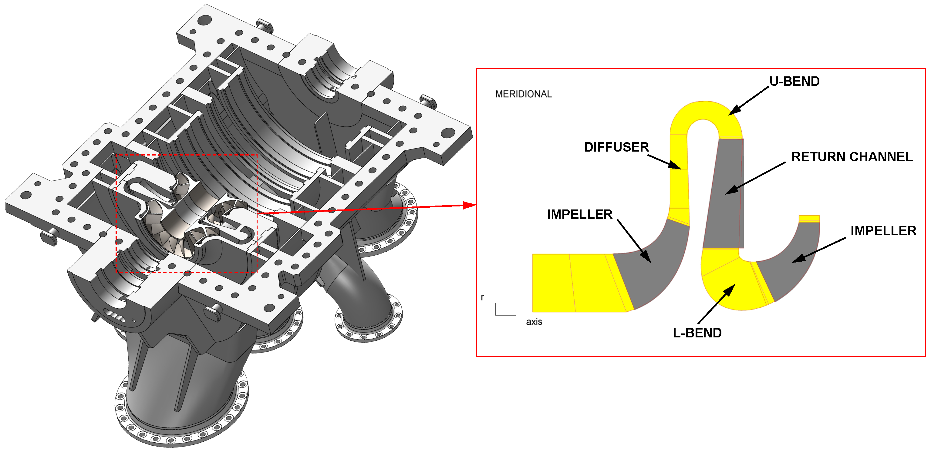
This chapter focuses on the parametric modeling and CFD simulation of the second-stage stationary components for the air compressor model illustrated in
Figure 1.
The research subject comprises a high-flow air compressor assembly, specifically including the first-stage components (impeller, diffuser, bend, and return channel) and the second-stage impeller. The impellers are shrouded and designed for a mass flow rate of 15.7 kg/s at a rotational speed of 9199 rpm, operating with a blade tip Mach number of 0.85. The entire compressor assembly achieves an overall static pressure ratio of 2.5. The first stage employs a vaneless diffuser, while the return channel is designed with straight vanes.
2.1. Initial Design and Parametric Modeling of the Second-Stage Stators
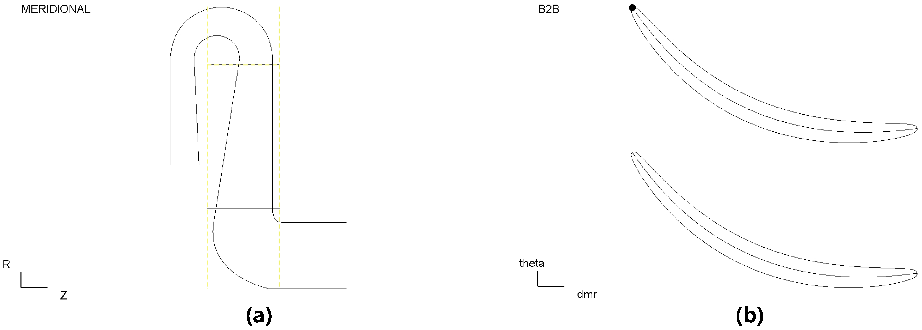
The second-stage stationary components are initially designed to maintain the geometric consistency with those of the first stage. The corresponding initial design parameters are listed in
Table 1. Schematic diagrams of the meridional plane and the Blade-to-Blade (B2B) view are presented in
Figure 2.
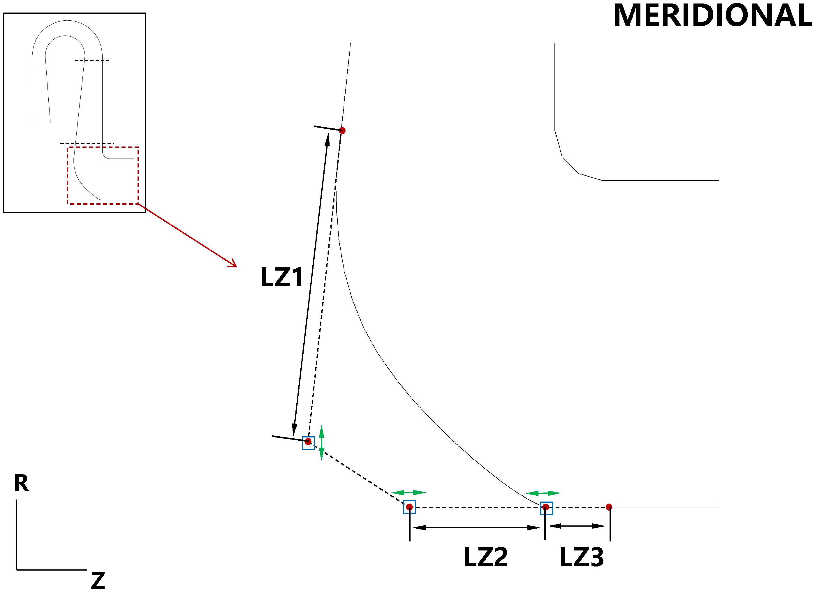
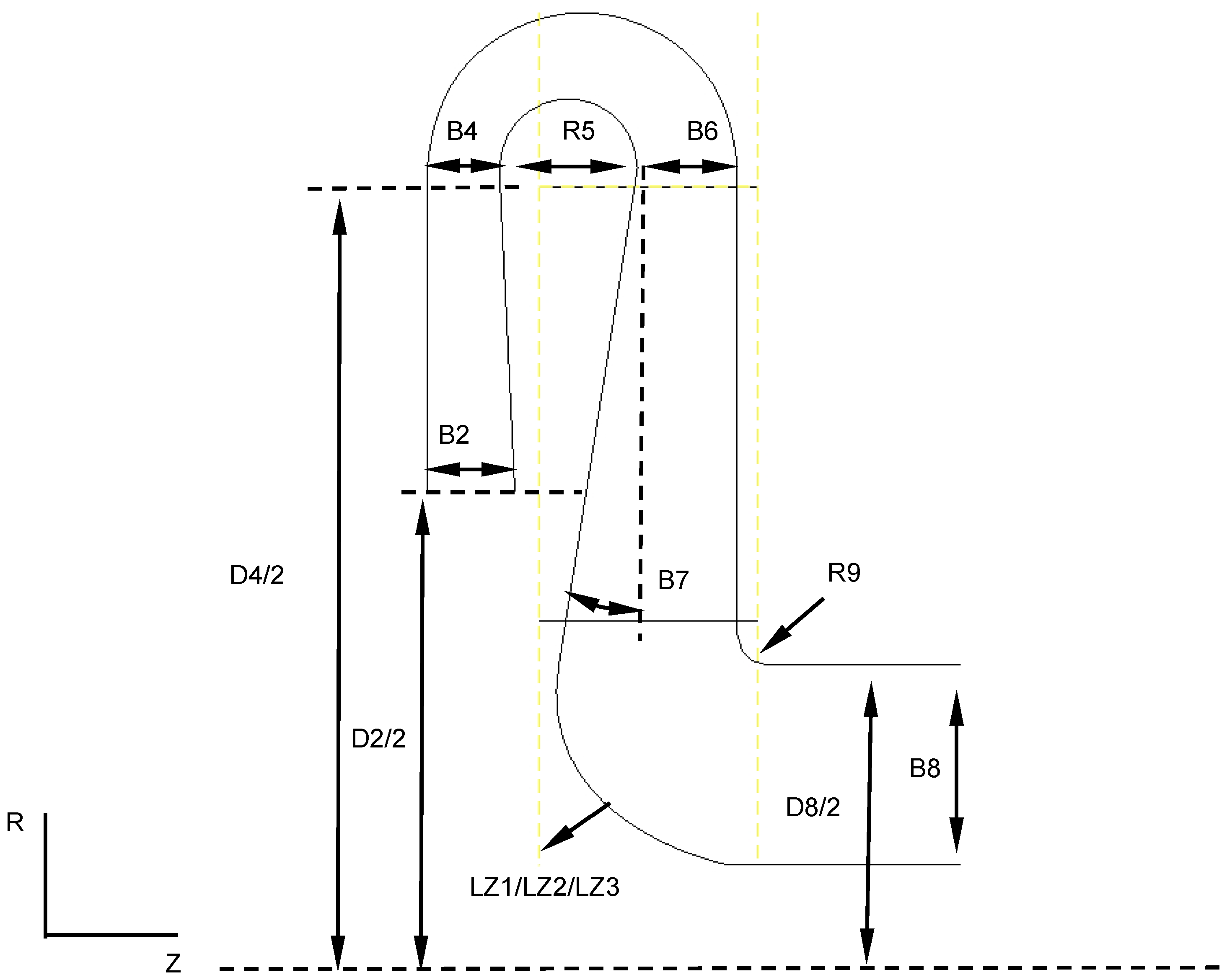
Since the inner and outer walls of the first-stage U-bend feature standard semi-circular profiles, the second-stage parametric model adopts this identical form. Consequently, the inner wall radius of the U-bend is defined as a variable parameter, while the geometry of the outer wall is derived from the diffuser outlet width, the bend inner radius, and the return channel inlet width. In contrast, the diffuser inlet and the L-bend outlet are constrained by the dimensions of the adjacent impellers. Consequently, they are treated as fixed parameters. The outer profile of the L-bend is constructed using a composite Bezier curve. This parametric methodology is illustrated in
Figure 3, where the curve is defined by three control points.
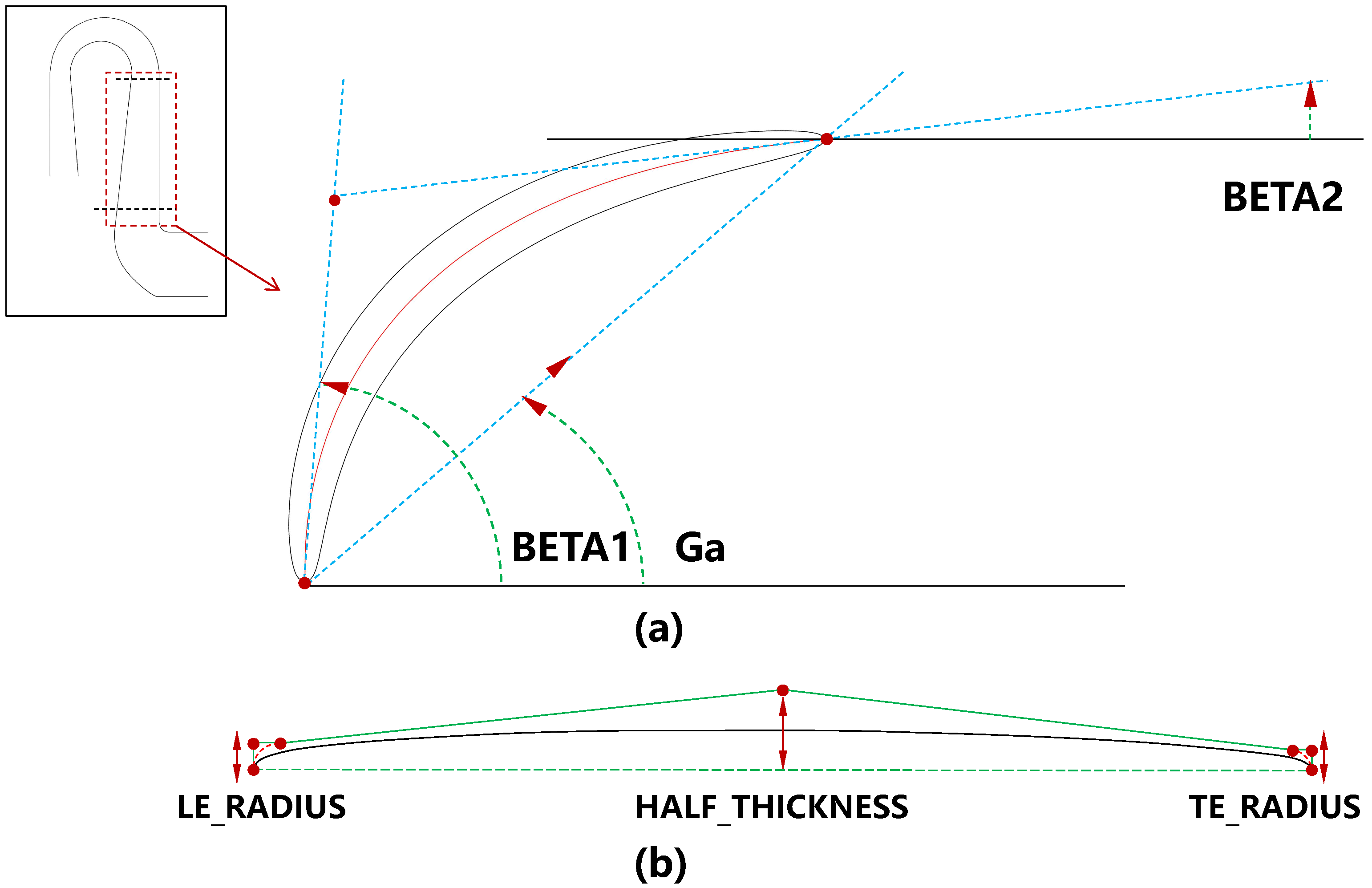
Additionally, the parametric model for the mean camber line of the second-stage return channel blade is established as illustrated in
Figure 4. The parametric model of the flow channel for the second-stage stationary components is depicted in
Figure 5.
2.2. CFD Simulation Analysis
Numerical simulations were performed on the initial design of the two-stage centrifugal compressor using the NUMECA software version 161 suite, a widely recognized CFD solver in the turbomachinery community. Its high fidelity in predicting complex three-dimensional internal flows and the aerodynamic performance of centrifugal compressors has been extensively validated by numerous experimental studies [
36,
37]. The computational domain encompasses the entire flow path, including the first-stage impeller (K1), diffuser, U-bend, return channel, L-bend, and the second-stage impeller (K2), followed by the adapted stators.
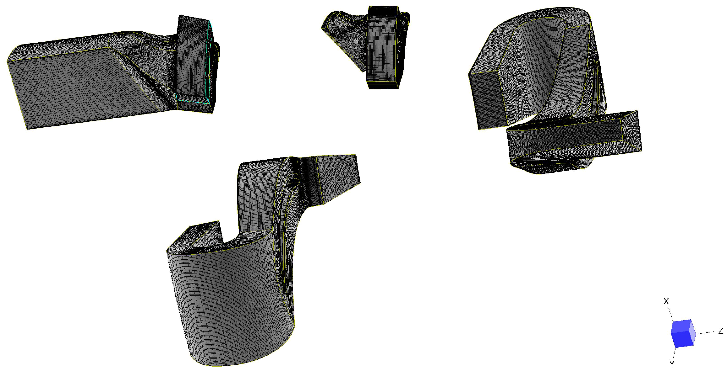
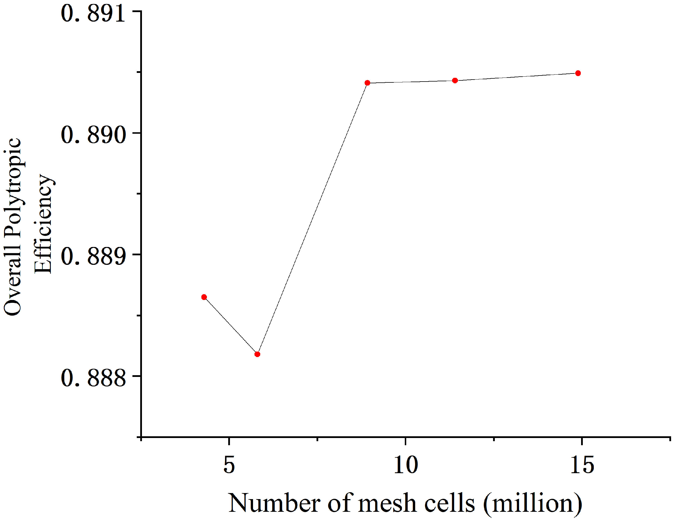
The computational mesh was generated within the AutoGrid5 module of NUMECA, resulting in a total grid of approximately 8.92 million cells. The computational mesh consists of approximately 1.96 million cells for the first-stage impeller, 2.53 million cells for the first-stage stators, 2.10 million cells for the second-stage impeller, and 2.33 million cells for the adapted stators, resulting in a total of approximately 8.92 million cells.
As shown in
Figure 6, the mesh is structured and employs a single-passage model of the computational domain. The grid quality satisfies the requirements for multigrid solvers in the circumferential, spanwise, and streamwise directions. Acceptable aspect ratios, expansion ratios, and minimum orthogonal angles were maintained according to the NUMECA solver standards. A grid independence study was conducted to verify that the chosen mesh density is sufficient. The results are presented in
Figure 7, indicate that the mesh configuration with a total of approximately 8.9 million cells was achieves a trade-off between accuracy and computational cost.
For the closure of the Reynolds-averaged Navier-Stokes (RANS) equations, the Spalart-Allmaras (S-A) turbulence model [
38] was selected. It has been demonstrated that for turbomachinery optimization involving attached flows and mild-to-moderate separations, the S-A model provides an excellent compromise between predictive accuracy and computational cost [
39,
40]. To ensure a
value of less than 5, the height of the first grid layer adjacent to the wall was set to 0.003 mm. Furthermore, extended inlet and outlet sections were appended to the inlet of the first-stage impeller and the outlet of the second-stage stators, respectively. This ensures the accurate capture of inflow and outflow conditions under realistic flow scenarios.
Both the first and second-stage impellers were set to a rotational speed of 9199 rpm. Under the design mass flow condition, the inlet boundary was defined by total temperature, total pressure, and flow direction. The outlet was specified by a mass flow boundary condition. The boundary condition settings are summarized in
Table 2.
Numerical calculations were executed using the aforementioned mesh and boundary conditions. The convergence criteria were established as follows. The global residuals were required to drop below . The mass flow conservation error between the inlet and outlet had to be within 0.5%. Additionally, all monitored performance indicators were required to stabilize.
2.3. Performance Evaluation and Flow Analysis
The static pressure recovery coefficient (
) and the total pressure loss coefficient (
) are adopted as key metrics to evaluate the aerodynamic performance of the stators. They are defined respectively as
where:
is the area-averaged static pressure at the inlet of the stators;
is the area-averaged pressure at the outlet of the stators;
is the mass-averaged total pressure at the inlet of the stators;
is the mass-averaged total pressure at the outlet of the stators.
The coefficient characterizes the capability of converting the kinetic energy into pressure energy. It is defined as the ratio of the static pressure rise to the inlet dynamic pressure, reflecting the pressure recovery capability. Conversely, the coefficient quantifies the total pressure loss relative to the inlet dynamic pressure. indicates the magnitude of irreversible flow losses within the component.
Numerical simulations of the initial design of two-stage centrifugal compressor were conducted at the design mass flow rate to obtain the performance parameters and the flow field data.
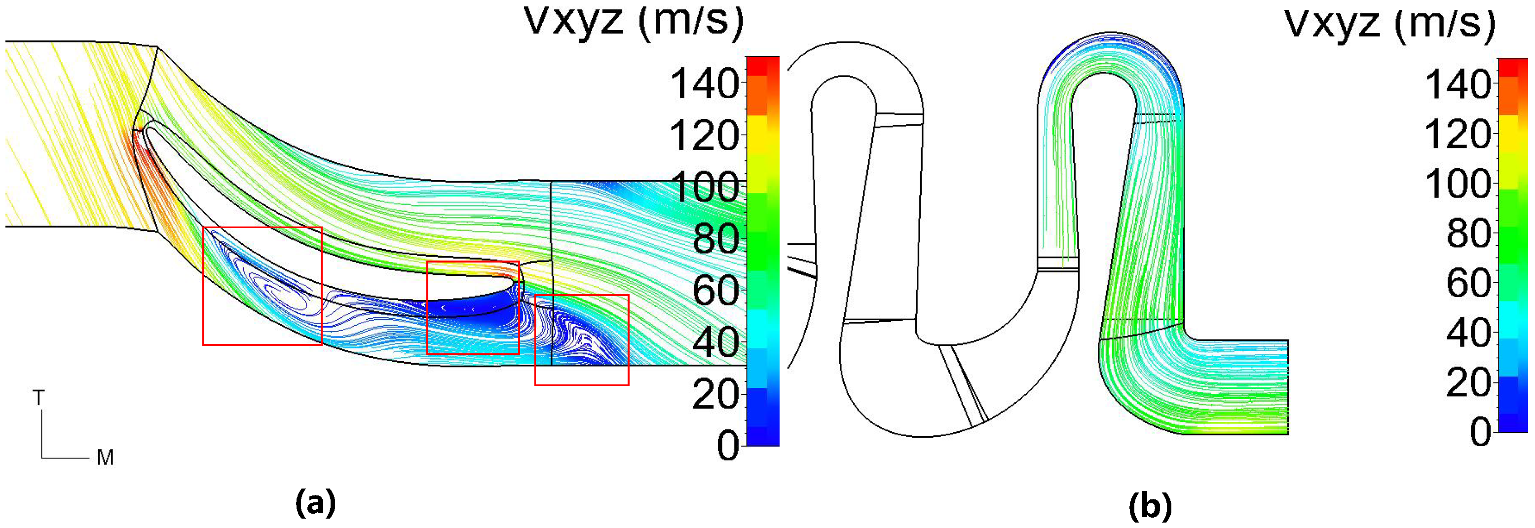
Figure 8 Absolute Velocity Field (denoted as Vxyz in the contours) displays the meridional streamlines and the Blade-to-Blade (B2B) flow field at 50% spanfor the second-stage stators.
Table 3 summarizes the key performance indicators of the compressor.
It is found that the flow within the second-stage diffuser and U-bend of the initial design appears smooth. However, within the return channel, three distinct low-velocity vortex regions are identified near the blade suction side and in the outlet wake. These low-velocity vortex regions have been marked by red boxes in
Figure 8. These vortices are typically associated with significant aerodynamic losses. This leads to an increase in total pressure loss and a reduction in pressure recovery capability. The outlet of these stators leads directly into the subsequent centrifugal impeller. Centrifugal impellers are typically designed for axial inflow. Therefore, the excessively large negative outlet circumferential flow angle observed in the stator is detrimental to the performance of the downstream impeller. This can cause increased incidence losses in the next stage.
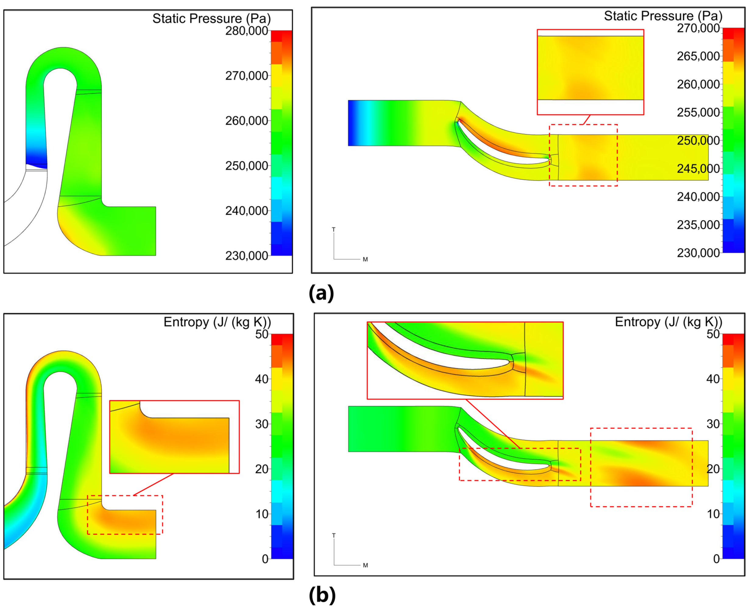
Figure 9 illustrates the static pressure and entropy distributions for the initial design at the design flow condition. This provides further insight into the flow field characteristics. The static pressure contours reveal a gradual pressure recovery along the flow path. Notable pressure gradients occur in the diffuser and return channel regions. Furthermore, the entropy distribution highlights the regions of increased entropy, which correspond to the areas of high irreversible losses. These regions have been marked by red boxes in
Figure 9b. Elevated entropy values are particularly prominent in the return channel vane wake and near the outlet. This confirms the presence of significant vortex-induced losses. The combination of low static pressure and high entropy in these regions substantiates that the initial design suffers from substantial flow separation and energy dissipation, particularly in the return channel.
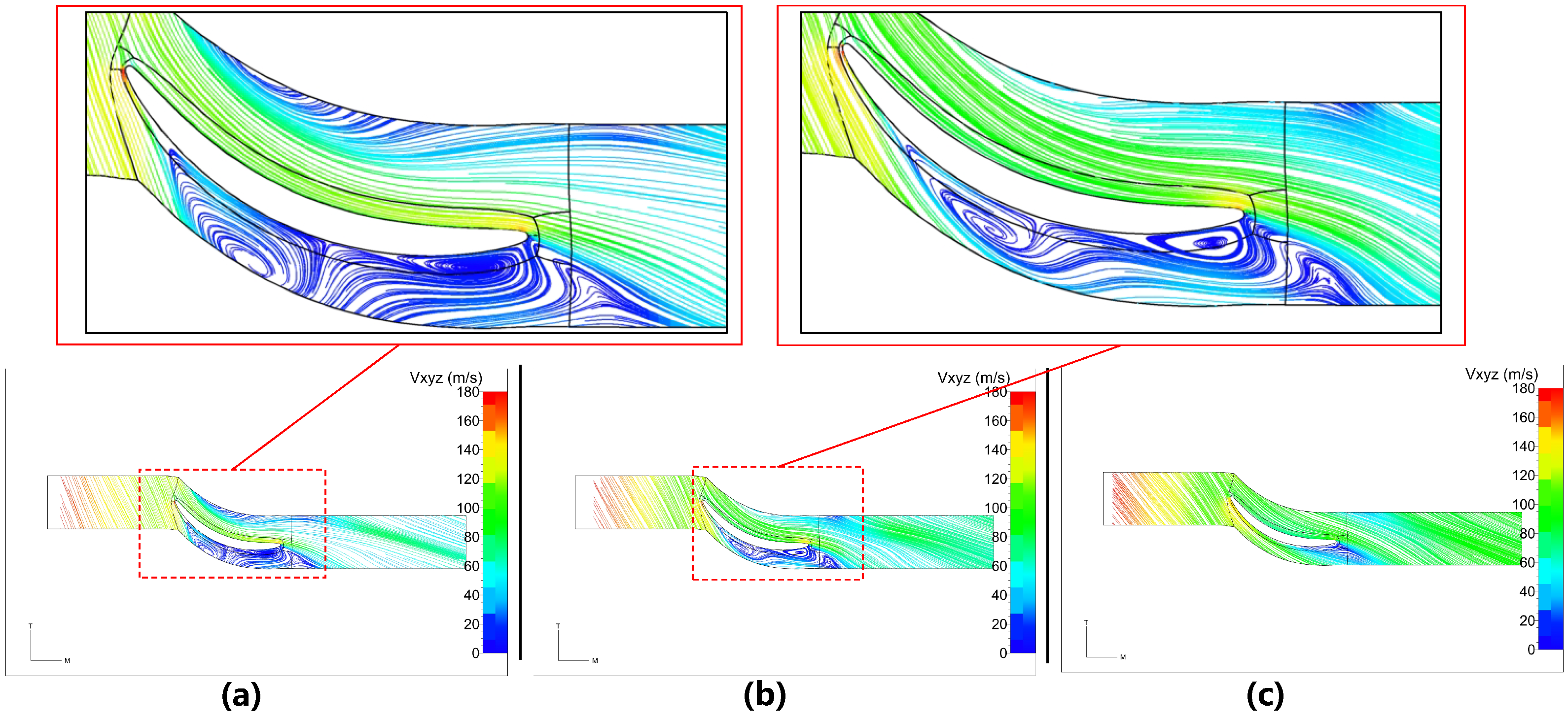
In addition, the CFD simulations were conducted for off-design conditions to further validate the comprehensive performance. Specifically, a high-flow condition (with the mass flow rate of 19 kg/s) and a low-flow condition (with the mass flow rate of 14 kg/s) were selected. The validation results are presented in
Figure 10 and
Figure 11. Key performance indicators of the initial design at these multi-flow conditions are presented in
Table 4.
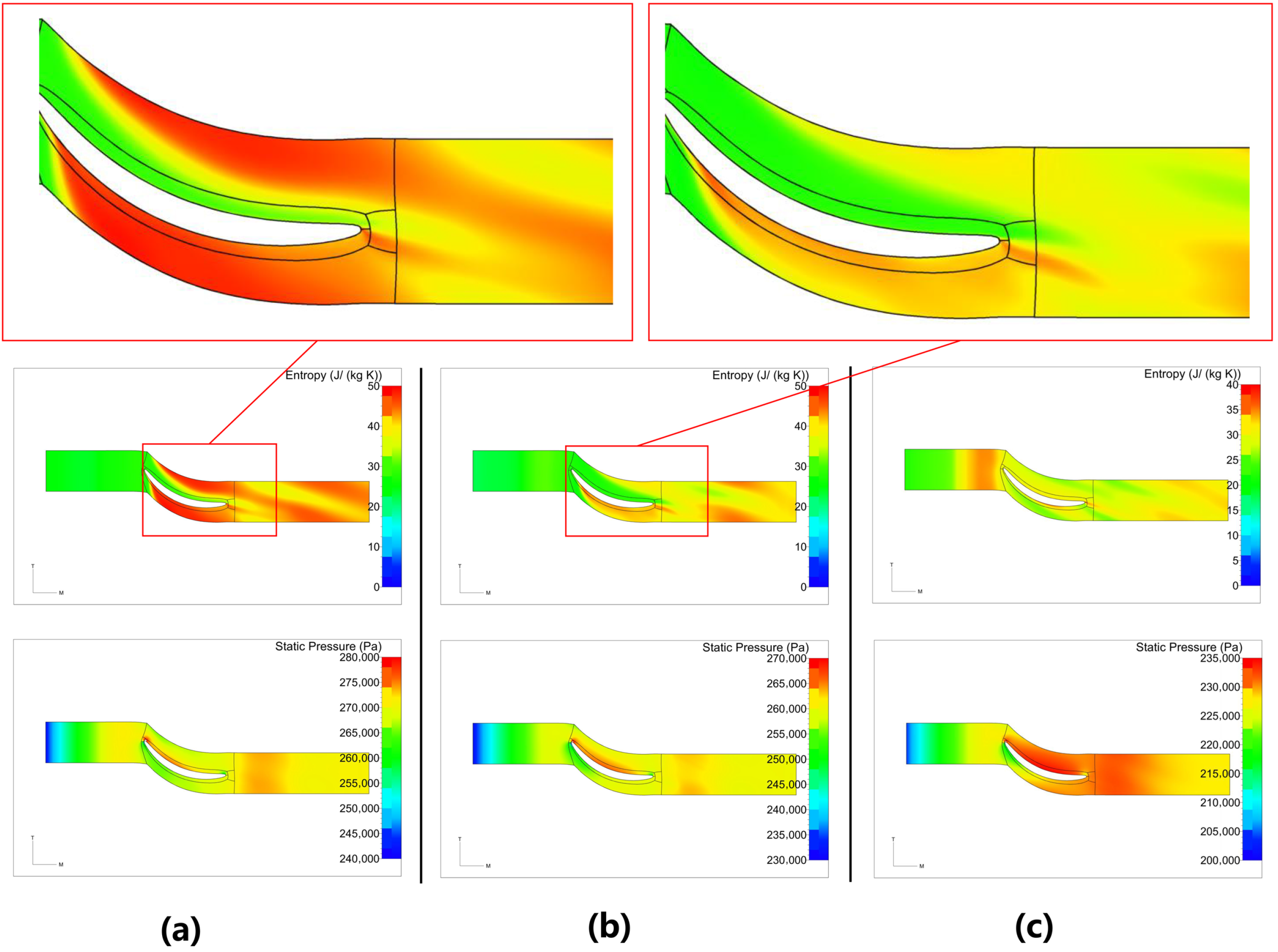
The validation results indicate that the initial design exhibits suboptimal performance across various flow conditions. At the low-flow conditions, the low-velocity vortices within the return channel persist. These low-velocity vortices are indicated by the red boxes in
Figure 10a. This leads to increased total pressure losses and reduced static pressure recovery. The outlet circumferential flow angle remains significantly negative, which is unfavorable for the subsequent impeller stage. In
Figure 11, the static pressure and entropy distributions at the low-flow conditions further confirm the existence of flow separation and energy losses in the return channel region. In the entropy distribution plot
Figure 11, there is a significant entropy increase region at the suction side of the return channel blade. These regions have been marked by red boxes in
Figure 11a,b. These findings underscore the necessity for optimization to enhance the aerodynamic performance of the second-stage stators.
Consequently, the subsequent optimization aims to mitigate the influence of the low-velocity vortices. It should also reduce the outlet circumferential flow angle as much as possible. The objective is not only to minimize the losses within the current stage but also to create more favorable inflow conditions for the downstream impeller.
3. Aerodynamic Optimization of the Second-Stage Stators
Building upon the established parametric modeling and the CFD simulation framework, this section details the optimization of the second-stage stators.
The general multi-objective optimization problem is mathematically formulated as
where:
represents the vector of objective functions to be minimized, with
X being the vector of design variables. The optimization targets two primary performance metrics averaged over
operating conditions (low, design, and high mass flow rate). These metrics are the overall polytropic efficiency
and the static pressure ratio
at operating point
. Specifically, the overall polytropic efficiency is selected as it directly quantifies the global energy conversion efficiency. Meanwhile, the static pressure ratio is chosen because it represents the fundamental aerodynamic duty of the stator components. They are defined respectively as
Here,
denotes the total enthalpy, and the subscripts
,
, and
s refer to inlet, outlet, and isentropic conditions, respectively;
represents the area-averaged static pressure. To maximize the performance, the objective vector
is defined by minimizing the negative averages of these metrics:
denotes the
i-th inequality constraint (
), where
L represents the total number of inequality constraints. These constraints enforce a limit on the outlet circumferential flow angle (
) at the design point. Additionally, they establish the minimum performance thresholds for efficiency and pressure ratio at each operating point. The constraints are expressed as follows:
where
is the maximum allowable flow angle magnitude. As a critical indicator of the inter-stage aerodynamic matching, strictly limiting this angle ensures near-axial inflow, thereby optimizing the incidence angle of the downstream impeller and guaranteeing the expected work input capacity of the downstream impeller. In addition,
and
represent the minimum acceptable efficiency and pressure ratio at the operating point
k, respectively.
and
define the lower and upper bounds of the design variables. These boundaries confine the search space to a physically feasible hyper-rectangle,
, ensuring geometric validity as
3.1. Optimization Strategy
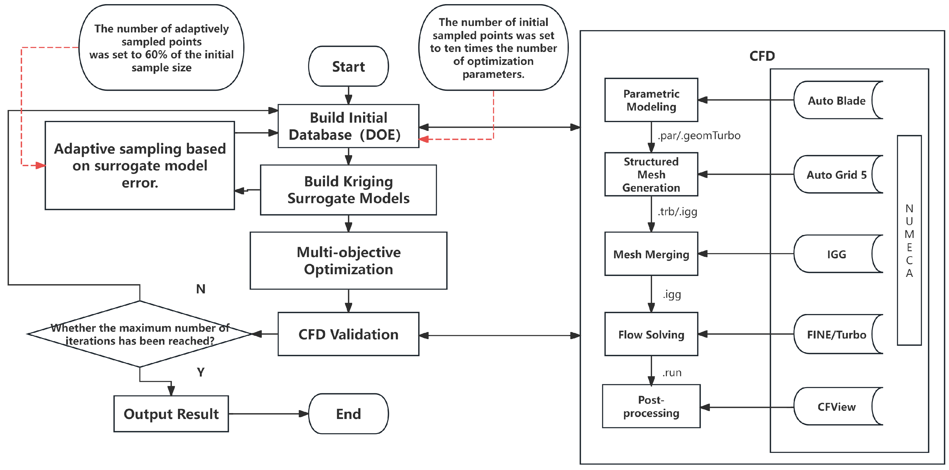
This study develops a CFD-based optimization framework to efficiently enhance the aerodynamic performance of the second-stage stators. The overall methodology integrates the parametric modeling, Design of the DOE technique, the surrogate-assisted optimization, and technique CFD validation. Given the high computational cost associated with direct CFD-based optimization, a surrogate model is employed to approximate the objective functions. This approach drastically reduces the number of required numerical simulations.
The technical route primarily consists of the following key steps:
- 1.
Sample Database Generation: The Latin Hypercube Sampling (LHS) method [
41] is utilized to generate an initial set of sample points within the design space. The size of this initial database is typically set to ten times the number of design variables. The LHS ensures that the sample points are uniformly distributed, providing excellent space-filling properties for initial model construction.
- 2.
Surrogate Model Construction and Adaptive Sampling: A Kriging surrogate model [
42] is constructed based on the initial samples. To improve global accuracy, an adaptive sampling strategy is implemented. This strategy identifies regions of high prediction error using the Leave-One-Out (LOO) cross-validation method [
43], and it iteratively adds new samples in these regions. The number of adaptively added samples is set to 60% of the initial sample size. This process efficiently refines the surrogate model, focusing computational resources where they are most needed.
- 3.
Multi-Objective Optimization: The refined Kriging model serves as a fast-to-evaluate objective function for the optimization process. A Multi-Objective Genetic Algorithm (MOGA) [
44] is thereafter employed to search for the Pareto-optimal front. The Tournament selection method is used to handle constraints [
45]. The concept of pareto dominance is applied to compare and rank thesolutions.
- 4.
CFD Validation and Final Selection: The optimal solutions obtained from the GA optimization on the surrogate model are validated through high-fidelity CFD simulations. The final design is selected from the validated Pareto-optimal solutions based on specific engineering requirements.
In summary, the CFD optimization methodology for the second-stage stators is illustrated in
Figure 12.
The final design is selected based on a comprehensive evaluation of both optimization results and engineering constraints. This integrated methodology significantly reduces the computational costs while ensuring robust, high-performance designs across multiple operating conditions.
3.2. Multi-Point Optimization of Second-Stage Stators
Multi-point optimization was conducted on the second-stage stators. Three representative operating conditions were selected for this process. These are the low-flow condition (mass flow rate of 14 kg/s), the design flow condition (mass flow rate of 15.7 kg/s), and the high-flow condition (mass flow rate of 19 kg/s).
As shown in
Table 5, fifteen design variables were selected, which encompass the key geometric features including for example the diffuser outlet width, the bend inner wall radius, the return channel inlet width, the return channel divergence angle, and the L-bend outlet width. Various parameters defining the blade mean camber line and the blade thickness were also included. The objectives were to maximize the average overall polytropic efficiency and the average overall static pressure ratio. Additionally, a constraint was applied to confine the outlet circumferential flow angle at the design flow condition to a narrow range close to zero.
Note that the overall polytropic efficiency and the overall static pressure ratio are selected as the primary optimization objectives, as they reflect the fundamental aerodynamic functions of the stator components: minimizing irreversible friction and vortex losses, and efficiently converting kinetic energy into static pressure. By maximizing the average values of these metrics across three operating conditions, the optimization framework ensures robust performance improvements over a wide operating range rather than focusing solely on a single design point.
In addition, the outlet circumferential flow angle constraint is a critical parameter in inter-stage aerodynamic matching. The downstream centrifugal impeller is geometrically designed for near-axial inflow (zero pre-swirl). A large residual swirl at the exit of the second-stage stator introduces unintended pre-swirl, which significantly alters the velocity triangle at the leading edge of the downstream impeller. This mismatch leads to severe incidence losses and may induce early flow separation. By constraining the outlet circumferential flow angle within a near-zero range (±0.01°), the optimized stator effectively eliminates the residual swirl and provides uniform axial inflow conditions for the subsequent stage.
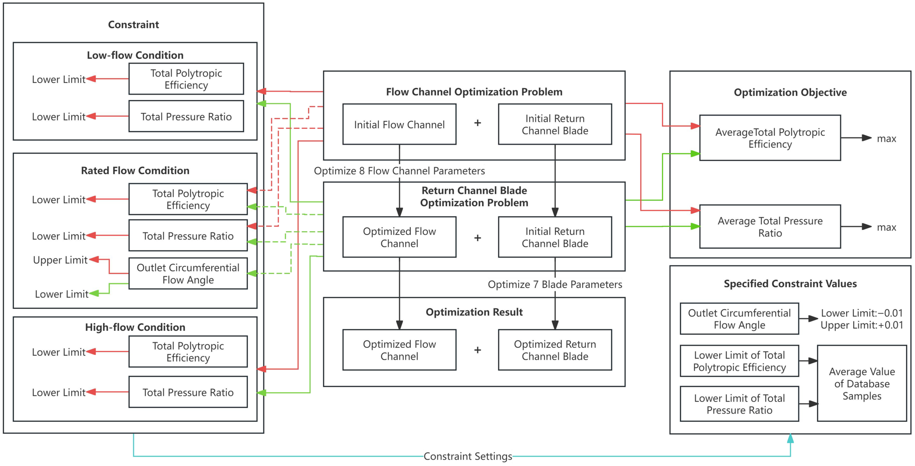
It is notable that, as the objectives are average-based, the optimization may sacrifice the performance at a single operating point in order to improve the overall average. To prevent this, minimum performance thresholds were established as constraints for key indicators at each of the three operating conditions. Minimum performance constraints on the overall polytropic efficiency and overall pressure ratio under each operating conditions serve as a safety margin. These threshold constraints ensure that the performance at the operating points does not fall below baseline the safety standards. This resulted in a total of six performance constraints. The definition of this multi-point optimization problem is illustrated in
Figure 13, with the design variables and their ranges shown in
Table 5.
The optimization process follows a methodology analogous to the single-point optimization. The LHS sampling method was utilized to construct the Kriging surrogate model. The MOGA was subsequently employed to solve the multi-point optimization problem.
The optimization involves fifteen design parameters, consisting of eight flow channel parameters and seven vane parameters. To reduce the dimensionality, this optimization problem follows a multi-step strategy, i.e., this problem is decomposed into two sub-problems. The first sub-problem focuses on optimizing the eight flow channel parameters. Empirical design experience suggests that the flow channel parameters have limited influence on the outlet circumferential flow angle. Therefore, only the constraints on the overall static pressure ratio and the overall polytropic efficiency at each operating condition were applied to the flow channel optimization. No constraint was imposed on the outlet flow angle for this step. Consequently, the flow channel optimization is formulated as an eight-parameter, two-objective and six-constraint problem. Similarly, for the sub-problem of return channel blade optimization, the constraints on the overall static pressure ratio and polytropic efficiency were applied. In addition, a constraint on the average outlet circumferential flow angle at the design flow condition was enforced. Thus, the blade optimization is formulated as a seven-parameter, two-objective and eight-constraint problem. The solution strategy follows a sequential approach. The flow channel parameters are optimized first. The resulting optimal flow channel configuration is then used as a fixed basis for the subsequent blade optimization. This process aims to achieve an optimal design for the second-stage stators across multiple flow conditions.
Table 6 presents the performance of the optimized second-stage stators following the multi-point optimization process.
It is found that compared to the initial design of second-stage stators, the multi-point optimized design demonstrates significant performance enhancements across various operating conditions. The improvement is particularly notable under the design flow condition. At the low-flow condition, the overall static pressure ratio is increased by 0.0749. The overall polytropic efficiency is improved by 1.81%. The total pressure loss coefficient is decreased by 0.1314. Meanwhile, the static pressure recovery coefficient is increased by 0.1540. At the design-flow condition, the overall static pressure ratio is increased by 0.0527. The overall polytropic efficiency is improved by 1.91%. The total pressure loss coefficient is decreased by 0.0429. The static pressure recovery coefficient is increased by 0.0781. At the high-flow condition, a slight performance decrement was observed. The overall static pressure ratio is dropped by 0.0181. The overall polytropic efficiency is decreased by 0.44%. However, these losses are minor compared to the substantial gains achieved at low and design flow conditions.
Particularly, a critical improvement is observed for the outlet circumferential flow angle. The value has been improved from an unfavorable −12.138° in the initial design to −0.083° in the optimized design. This near-zero angle indicates that the residual swirl has been effectively eliminated. Consequently, the flow entering the subsequent impeller is almost purely axial. This is essential for minimizing the incidence losses and enhancing the aerodynamic stability of the downstream stage.
Overall, the multi-point optimization has led to substantial performance improvements in most operating conditions. The optimal design has effectively addressed the flow issues identified in the initial design. This has resulted in a more efficient and aerodynamically superior second-stage stators.
3.3. Flow Analysis of Optimized Design
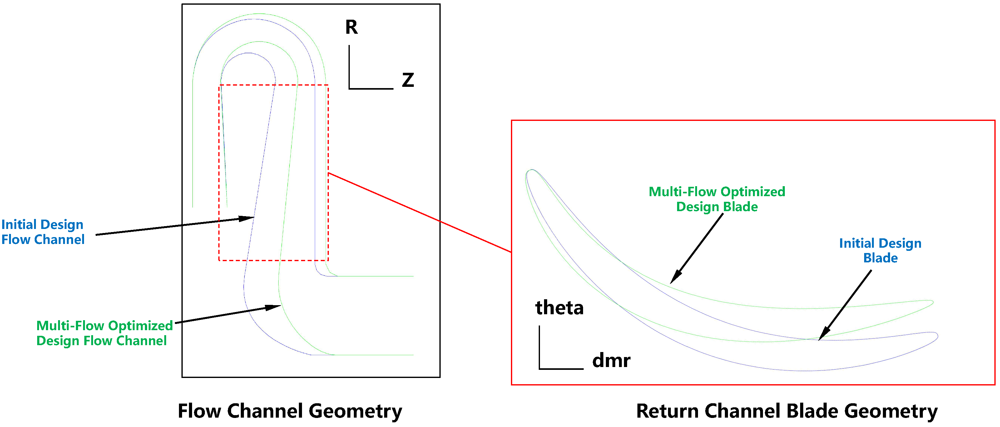
Firstly, a geometric comparison between the initial design and the multi-point optimized design is presented in
Figure 14. The optimized design is highlighted in green, and the initial design is marked in blue.
It reveals that the optimized design features a narrower diffuser outlet width and a reduced return channel inlet width. This reduction in flow passage area accelerates the fluid velocity within the channel. It helps to suppress the flow separation and vortex formation, particularly under low-flow conditions. However, under high-flow conditions, where the flow rate and absolute velocity are already high, further reduction in the cross-sectional area leads to excessively high Mach numbers within the passage, causing high friction losses and performance under degradation high-flow conditions. Furthermore, the optimized return channel blade geometry plays a decisive role in correcting the outlet flow angle. The return channel vanes in the optimized design exhibit a smaller stagger angle and a more moderate inlet angle. These adjustments contribute to improved flow guidance and more effective flow turning. Crucially, the geometric reason for the significant reduction in the outlet circumferential flow angle is the increase in the blade outlet angle. This geometric adjustment effectively enhances the blade’s ability to turn the flow, resulting in a smaller exit circumferential flow angle. It ensures that the flow exits the stators in a nearly axial direction. For the L-bend section, the optimized design features a larger fillet radius and a more gradual curvature. These modifications smooth the flow path, reducing turbulence and energy losses as the fluid navigates the bend.
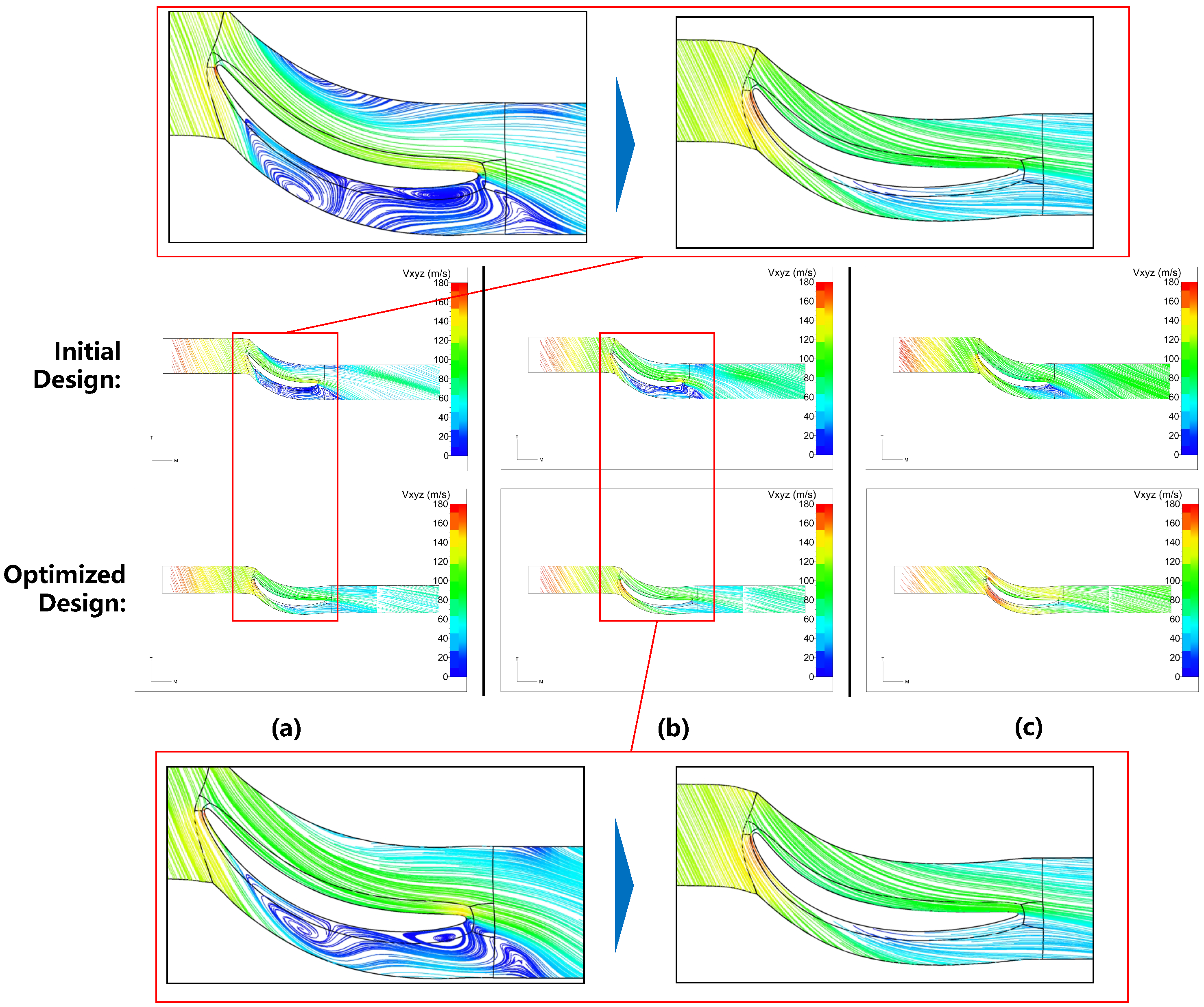
Secondly,
Figure 15 illustrates the velocity streamlines for the initial and optimized designs under low-flow, design-flow, and high-flow conditions. For the initial design, pronounced low-velocity vortex regions are evident near the suction side of the return channel vanes, particularly at the low-flow condition, indicating significant flow separation and energy dissipation. To reduce these severe aerodynamic losses at the design and low-flow conditions, the blade angles of the return channel vanes were strategically adjusted during the multi-point optimization. From the optimized results, the optimized design effectively eliminates the low-velocity vortex regions at both low and design flow rates. Specifically, under the low-flow and design-flow conditions, the aforementioned optimization eliminates the three low-velocity vortex regions occurred on the suction side of the return channel vanes in the initial design. This leads to smoother and more uniform streamlines, demonstrating significantly improved flow stability. To eliminate these separations, the optimizer adjusted the blade inlet angle (BETA1) and stagger angle (Ga) to perfectly align the leading edge with the highly swirled incoming flow at lower mass flow rates. However, it should be noted that this geometric adjustment inherently alters the incidence matching at the high-flow condition, leading to a slight performance degradation. From an engineering perspective, such a trade-off is acceptable. Specifically, the foremost concern for centrifugal compressor operation safety is surge prevention. In practical engineering applications, centrifugal compressors rarely operate near the choke limit, with such high-flow conditions typically limited to specific scenarios like overload operation. Therefore, prioritizing the suppression of flow separation at low-flow conditions to extend the surge margin is a necessary and favorable compromise even at the expense of a minor performance drop near the choke limit.
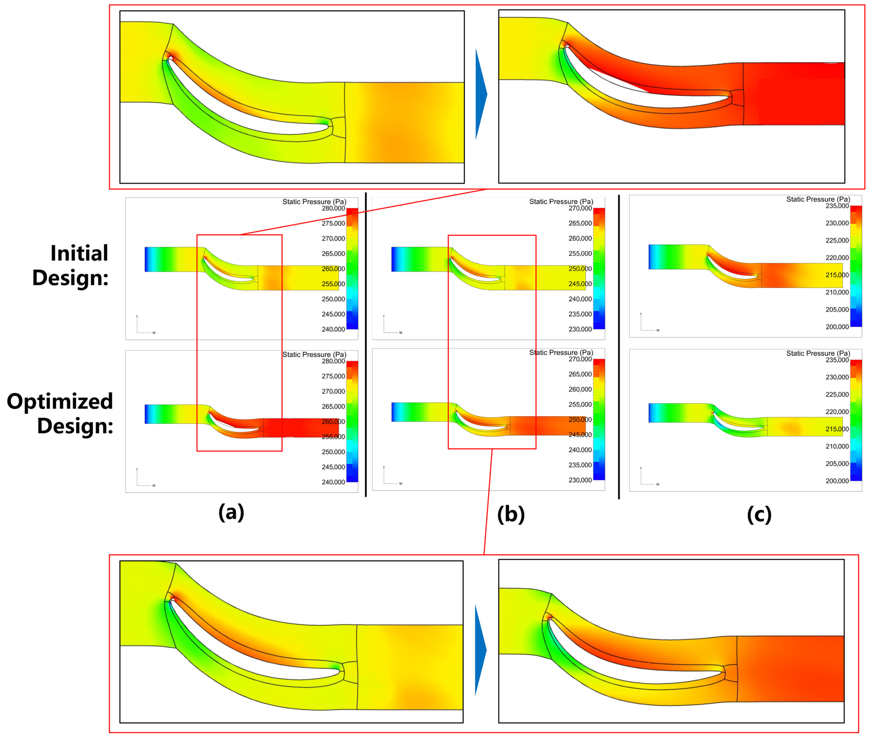
Thirdly,
Figure 16 compares the static pressure distributions of the initial and optimized designs under different operating conditions. In the initial design, the low-pressure regions are observed near the suction surface and outlet of the return channel vanes, which correspond to the magnitude of flow losses. In contrast, the optimized design achieves an overall increase in static pressure under all the three operating conditions, along with a more uniform static pressure distribution, which is beneficial for the work input to the subsequent stage. These results indicate an improvement in pressure recovery capability. Specifically, under low-flow conditions, the outlet static pressure increases by nearly 7000 Pa; under design-flow conditions, it increases by approximately 5000 Pa; and under high-flow conditions, it increases by 1500 Pa.
Finally,
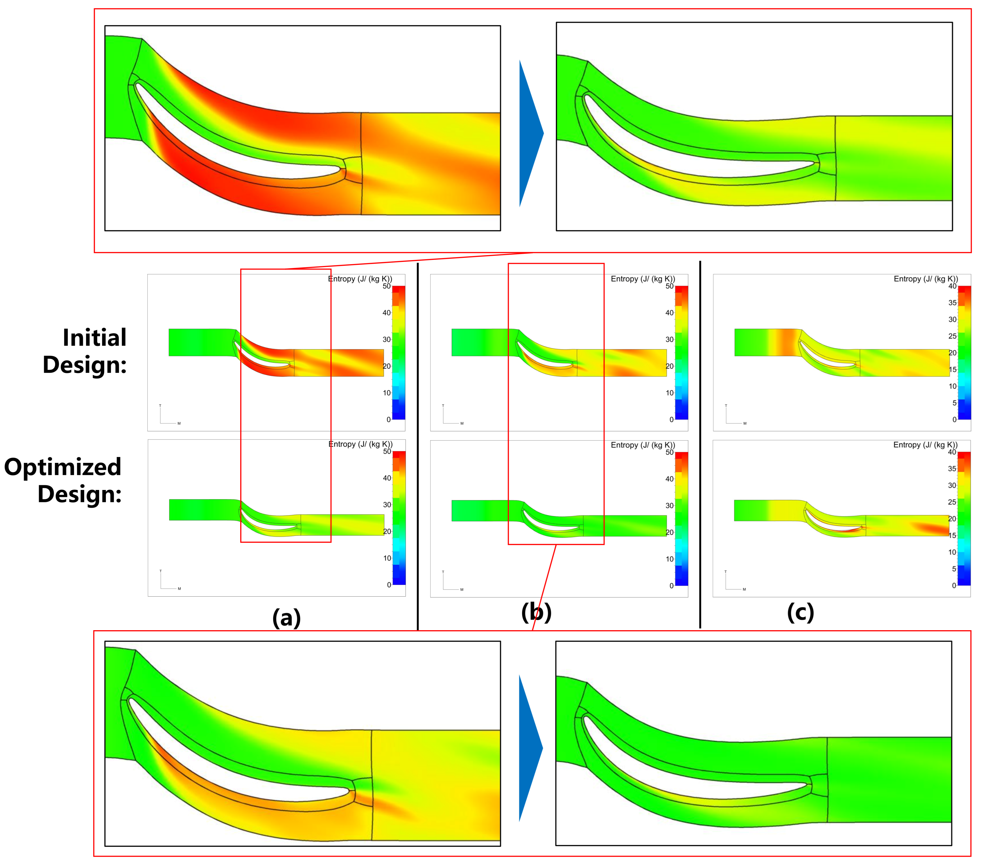
Figure 17 presents the entropy distributions for the different designs under various flow conditions. For the initial design, high entropy values are observed in the wake regions and near the outlet under low-flow and design-flow conditions. Under these two operating conditions, the entropy generation is primarily concentrated on the suction side of the return channel vanes. At the low-flow condition, the entropy values in most regions downstream of the vane cascade exceed approximately 40 J/(kg·K) for the initial design; whereas for the optimized design, few regions exhibit the entropy values above 40 J/(kg·K), and the entropy generation on the suction side of the return channel vanes is substantially reduced. At the design-flow condition, the initial design shows the entropy values approximately larger than 35 J/(kg·K) in most downstream regions, while the optimized design presents a uniform entropy distribution, with the values around 30 J/(kg·K), and the entropy generation on the suction side of the return channel vanes is significantly decreased. A comparison of the averaged entropy at the outlet shows that, compared to the initial design, the optimized design achieves a reduction of 5.96 J/(kg·K) at the low-flow condition and 6.2553 J/(kg·K) at the design-flow condition, whereas it has a slight increase of 1.23 J/(kg·K) at the high-flow condition. The entropy distributions indicate that the low-velocity vortices on the suction side of the return channel vanes leads to irreversible losses. The optimized design exhibits lower entropy values under both low-flow and design-flow conditions. At the high-flow condition, only a marginal entropy increase is observed compared to the initial design.
In summary, compared with the initial design, the multi-point optimized design achieves superior flow field characteristics. It effectively eliminates low-velocity vortex regions, improves static pressure recovery, and reduces entropy generation. This leads to enhanced aerodynamic performance at the design condition and further improves the off-design performance of the centrifugal compressor. From an engineering perspective, the optimization results presented in this study are entirely acceptable.
4. Conclusions
This study established a parametric modeling and multi-point aerodynamic matching optimization framework for the second-stage stators of a multi-stage air compressor. The parametric model was constructed based on the geometric configuration of the existing first-stage components to ensure consistency. Utilizing the NUMECA software suite, a comprehensive design workflow was implemented. This encompassed the initial design, the internal flow field simulation, and the aerodynamic optimization. Through a sequential optimization strategy that progressed to a multi-point optimization over three flow rates, a final optimized design was obtained. This optimized design demonstrates excellent performance at the design-flow condition and has robust stability performance under off-design conditions. The results demonstrate that the optimized design achieves a 2.17% improvement in the overall polytropic efficiency and a 12.01% improvement in the static pressure recovery coefficient at the design condition, along with a notable reduction in the outlet circumferential flow angle to 0.663°. Under multi-condition operation, the optimized stator exhibits enhanced performance stability with the overall polytropic efficiency improved by 2.06% and the static pressure recovery coefficient improved by 23.31% at the low-flow condition.
In addition, this study offers several key engineering insights. It is demonstrated that the inter-stage aerodynamic matching is sensitive to the inlet and stagger angles of the return channel blades. Moderately restricting the cross-sectional area and adjusting the flow turning capability can effectively suppress the low-flow hub-corner stall, albeit at the cost of a slight, yet engineeringly acceptable, efficiency drop at the high-flow condition. Practically, the proposed Kriging-GA coupled optimization framework provides a highly automated, multi-condition design template for the multi-stage centrifugal compressors, significantly reducing the reliance on traditional trial-and-error empirical approaches.
However, the current optimization and performance evaluations are fully based on CFD numerical simulations, and actual experimental testing of the optimized stator has not yet been carried out. Therefore, the experimental validations of optimized configurations on a compressor test rig will be the future work.