Article

Characterization of Micro-Hole Quality in Alumina Ceramics by Picosecond Laser Ring-Cut Drilling

1
School of Mechanical Engineering, North University of China, Taiyuan 030051, China
2
Shanxi Key Laboratory of Advanced Manufacturing Technology, North University of China, Taiyuan 030051, China
*
Author to whom correspondence should be addressed.
Machines 2026, 14(2), 180; https://doi.org/10.3390/machines14020180
Submission received: 29 December 2025 / Revised: 26 January 2026 / Accepted: 2 February 2026 / Published: 4 February 2026
(This article belongs to the Special Issue Composite Machining in Manufacturing)

Abstract

In this study, a novel picosecond laser ring-cut drilling method was employed to drill holes in alumina ceramics. The morphology, dimensions, taper angle, and heat-affected zone (HAZ) of the resultant micro-holes were systematically characterized under various laser processing parameters. The crystal structure, microstructure, and elemental composition of micro-holes processed under specific parameters were characterized. The results showed that the micro-hole entrance and exit dimensions and HAZ area increased with increasing spot-scanning number. However, the micro-hole taper angle initially decreased before stabilizing with an increasing spot-scanning number. Furthermore, the micro-hole entrance and exit dimensions and HAZ area gradually decreased with increasing spot-scanning speed. Conversely, the micro-hole taper angle increased with increasing spot-scanning speed. Additionally, the micro-hole entrance and exit dimensions and HAZ area gradually increased with increasing average power. However, the micro-hole taper angle gradually decreased with increasing average power. Under processing parameters of spot-scanning number N = 90, scanning speed v = 600 mm/s, and average power P = 24 W, the micro-holes exhibited a taper angle α of 4.32° and a HAZ width of approximately 0.207 mm2. In contrast to the large bright grains on the original substrate, fine grains were observed around the machining area. Compared to the original substrate surface, the percentage of oxygen atoms decreased, whereas the percentage of aluminum atoms increased at the micro-hole edge and HAZ surface. The results of this study have potential applications in the field of ceramic manufacturing.

1. Introduction

Alumina ceramic substrates with excellent dielectric properties, high thermal conductivity, and chemical stability are key materials for new-generation microelectronic systems and devices. They are crucial in aerospace, 5G communications, high-power semiconductor devices, and high-density LED lighting [1,2,3,4]. In particular, the efficient fabrication of high-quality micro-hole structures is fundamental for achieving system interconnections and device packaging [5]. However, as a typical hard and brittle material, alumina ceramics exhibit high hardness and low fracture toughness. These characteristics make traditional machining prone to matrix fracture, and special processing methods also have significant limitations. Consequently, conventional micro-hole drilling technology struggles to meet precision machining requirements [6,7,8,9]. Laser processing technology has emerged as an efficient solution for the precision machining of alumina ceramic micro-hole. Its advantages include non-contact machining, no tool wear, environmental friendliness, and highly controllable processing [10,11,12].
Laser drilling, an efficient non-traditional micro-hole machining technology, has gained widespread industrial application owing to its high speed, high accuracy, low cost, and absence of tool wear [13,14,15]. Laser drilling technology can be categorized into three types based on the pulse duration: millisecond lasers, nanosecond lasers, and ultrashort-pulse lasers (picosecond and femtosecond) [16]. Ultrashort-pulse lasers (picosecond and femtosecond), owing to their low thermal effect and high machining accuracy, have emerged as a precision machining research hotspot [17]. Conventional millisecond/nanosecond laser processing of alumina ceramics has been extensively studied. For example, Kacar et al. [18] conducted drilling experiments on 10 mm thick alumina ceramics using an adjustable pulse duration (0.3–50 ms) Nd:YAG laser. They found that, under single-pulse conditions, the hole entrance diameter increased with the pulse duration or peak power. In contrast, during multi-pulse through-hole processing, the entrance dimensions stabilized, whereas the exit dimensions expanded with increasing pulse duration, ultimately forming zero- or even negative-taper hole structures. Hanon et al. [19] conducted a systematic investigation into the effects of millisecond laser parameters on the drilling quality of alumina ceramics. They found that as the pulse number increased from 10 to 100, the hole diameter and depth exhibited saturation characteristics, whereas the positive defocus increased the taper angle. EDS analysis confirmed that the chemical composition of the hole wall remained consistent with the base material, despite significant changes in its color. Yan et al. [20] deeply analyzed how peak power, pulse duty cycle, and repetition frequency affect pore size and slag deposition. They noted that the melt front size and temperature distribution are key factors determining hole formation and spatter deposition, which are significantly regulated by the combined laser parameters. Bharatish et al. [21] optimized laser power and scanning speed parameters to investigate residual stress distribution. Their study revealed that cracking initiated when the initial tensile residual stress exceeded the material’s tensile strength. Additionally, cyclic thermal stresses from high power and low scanning speed damage pore structures. Shaheen et al. [22] demonstrated that for 0.5 mm thick alumina ceramics, 193 nm laser ablation achieved an 80 nm/pulse ablation rate with a 25 μm beam diameter, decreasing to 50 nm/pulse with an 110 μm beam. However, while millisecond lasers achieve high material removal rates in alumina ceramic drilling, their significant thermal effects can cause defects, such as insufficient melt discharge, large taper angles, and micro-cracks [18,20]. The high peak power of nanosecond lasers can trigger plasma shielding, limiting the energy coupling efficiency and potentially causing surface yellowing and irreversible damage [23,24].
Ultrafast lasers (e.g., femtosecond and picosecond) generate minimal heat-affected zones (HAZ) due to their extremely short pulse durations, which limit thermal diffusion [25,26]. In long-pulse lasers, material removal primarily occurs via melting. By contrast, ultrashort-pulse lasers enable material removal through solid-to-vapor transitions, thereby minimizing the HAZ area [27]. Some studies have explored femtosecond laser applications in the processing of ceramic materials. For instance, Li et al. [28] used a 775 nm wavelength femtosecond laser system to experimentally investigate the impact drilling of 0.39 mm and 0.48 mm thick alumina ceramic substrates. The results demonstrate a significant linear increase in drilled-hole diameter with increasing laser energy fluence, confirming a positive correlation between energy density and material removal efficiency during femtosecond laser processing. Ren et al. [29] used water-assisted femtosecond laser drilling to fabricate holes in alumina ceramics. They characterized the hole morphology, diameter, taper angle, cross-sectional area, and sidewall properties, and compared the results obtained under air and water-assisted conditions. They found that this method significantly enhanced drilling efficiency and quality, particularly at lower pulse repetition rates. However, femtosecond lasers are typically more complex and expensive to fabricate. The technology required to generate such short pulses involves advanced equipment and high operating costs. Although minimal thermal effects offer significant benefits, they must be weighed against the higher costs and complexities [30,31]. In contrast, picosecond lasers offer lower costs while maintaining a minimal HAZ area, making them highly valuable for ceramic micro-hole machining research. Some studies have explored picosecond laser applications in ceramic subtractive processing. For example, Amsellem et al. [27] used a picosecond fiber laser-based subtractive manufacturing technique to remove material from reactively bonded SiC surfaces or create micro-models with minimal surface damage, high surface quality, and accuracy. They investigated several laser processing parameters to optimize focus position, laser power, line speed, oscillation frequency, oscillation mode, and number of passes. These established parameters for shallow yet high-precision SiC cutting with a material removal rate of 2 mm. Beausoleil et al. [32] used a 1030 nm wavelength picosecond fiber laser to process 635 μm and 1270 μm thick alumina ceramics. They investigated the effects of different laser processing parameters on the cut shape and quality. The laser cutting process developed through these experiments is an effective and efficient fabrication tool that can be integrated into engineering web shaping systems. Significant time and effort have been invested in understanding how various laser process parameters (e.g., laser power, scanning speed, polarization, focus position) affect workpieces [33,34,35].
Picosecond lasers achieve precision drilling on alumina ceramics, signifying more than a mere replacement for traditional processing methods; they represent a significant evolution in advanced manufacturing paradigms. Through its unique ultrashort pulse mechanism, this technology effectively addresses the inherent processing challenges posed by the high hardness, brittleness, and melting point of alumina ceramics, thereby creating new possibilities at both the industrial application and functional realization levels. Although numerous studies have focused on the deep cutting of ceramics, limited research has explored alumina processing using ultrashort pulsed lasers (pulse width < 10 ps). This is particularly true for the ultrashort pulsed laser perforation of alumina ceramics, where the low thermal generation material removal mechanism significantly reduces the HAZ area [36,37]. Consequently, a picosecond laser ring-cut drilling method was employed to drill micro-holes in the alumina ceramics. The morphology, dimensions, taper angle, and HAZ area of the holes obtained under different laser processing parameters were analyzed through well-designed laser drilling experiments. The effects of laser scan number, scanning speed, and average power on the micro-holes were also examined. Based on these results, the crystal structure, microstructure, and elemental composition of the processed micro-holes were characterized under the following processing parameters: spot-scanning number N = 90, spot scanning speed v = 600 mm/s, and average power P = 24 W. This study demonstrates the significant potential of this approach for industrial applications.

2. Experimental Procedure

As shown in Figure 1a, the experimental picosecond laser processing platform comprised an infrared picosecond pulsed laser, optical transmission system, focusing system, control system, and three-axis motion platform. This platform enables high-precision and high-efficiency micro-hole drilling, which is particularly suitable for hard and brittle materials such as alumina ceramics.
The experiments used a 1064 nm wavelength picosecond laser (PINE3-1064-30B, Wuhan Huaray Precision Laser Co., Ltd., Wuhan, China) featuring an ultrashort pulse duration (<10 ps), a continuously adjustable pulse repetition frequency (1 kHz–1 MHz), and a maximum average power of 30 W. The specific parameters are shown in Figure 1b. The laser beam travels through the optical transmission system, reflects off the mirror, and enters the scanning galvo system. The scanning galvanometer system precisely controlled the deflection angle of the laser beam, enabling accurate positioning and complex path planning on the surface of the workpiece. Subsequently, a 100 mm focal length field mirror focused the laser beam to a spot diameter of approximately 20 μm, which was applied to the workpiece surface for micro-hole processing. The experiment was conducted in air. To effectively control chip contamination in the machining area, the experimental system integrated a dedicated dust collection device to collect drilling residues.
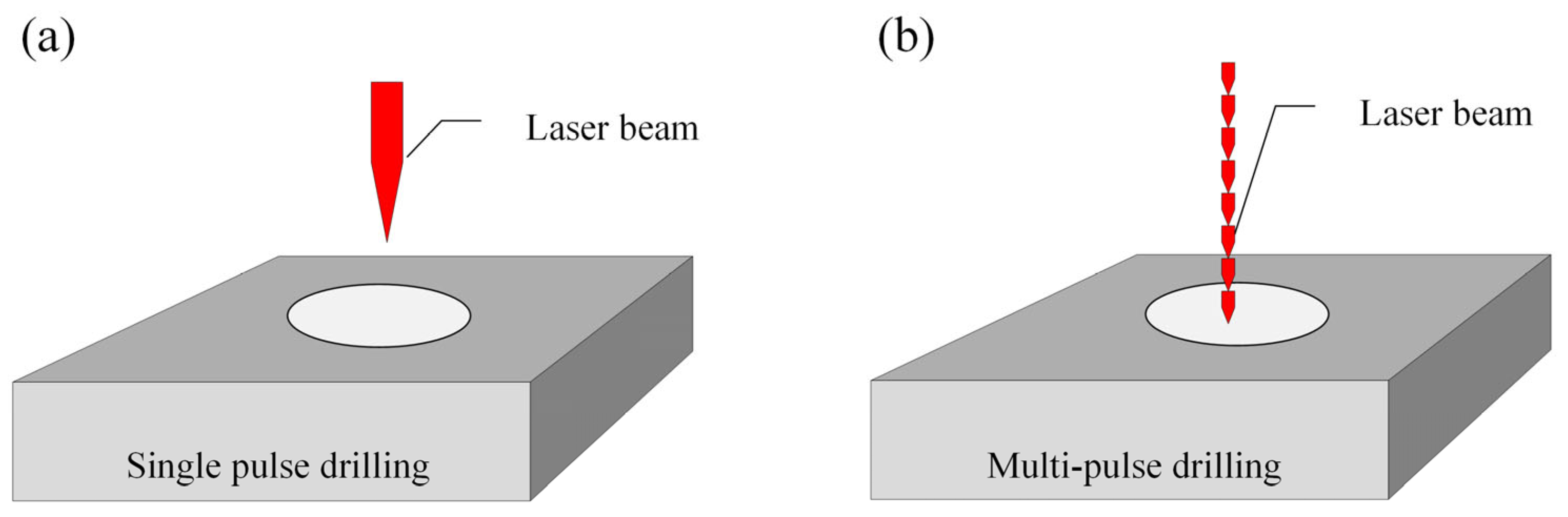
From the perspective of the relative motion between the laser and workpiece, all laser drilling processes can be categorized into two core types: impact drilling with no relative motion and trajectory drilling with relative motion. These two categories exhibit significant differences in terms of processing capabilities, applicable scenarios, and technical limitations. Traditional single-pulse and multipulse drilling fall under the category of impact drilling with no relative motion. Figure 2 illustrates schematic diagrams of both laser drilling methods. In impact drilling, the laser beam and workpiece remain stationary relative to each other during processing, and material removal is achieved through localized irradiation. In this process, the diameter of the formed hole is directly constrained by the laser beam waist radius, and the machining accuracy is strongly correlated with the beam focusing characteristics. However, during process parameter control, it was discovered that as key parameters, such as the number of laser pulses and single-pulse energy, increased, the hole depth gradually exhibited a saturation effect. That is, once the parameters exceed a threshold, the hole depth no longer increases with further parameter increases. This characteristic directly limits its engineering applications in deep-hole machining scenarios.
In this study, the picosecond laser ring-cut drilling technology was employed for drilling. The filling circle spacing refers to the radial distance between two adjacent scanning rings when a laser ring scan is used to process circular holes. The filling circle spacing refers to the radial distance between two adjacent scanning rings when laser ring scanning is used to process circular holes. This directly determines the coverage density of the scanning path within the processing area. As shown in Figure 1c,d, the outermost circle of each layer had a diameter of 300 µm and was spaced 30 µm apart from the next circle, with a total of five rings. The laser beam was focused on the top surface of the workpiece, and the focus was not adjusted with drilling depth. First, the laser performs a circular scan on the workpiece to form an initial pre-drilled micro-hole in the workpiece. Subsequently, the machining process centers on this hole, progressively moving outward, layer by layer, along a circular path. The intermediate circular beams enlarge the hole diameter, whereas the outermost circular beams refine the hole shape by removing the material layer by layer to complete the machining process. This process continues until the workpiece is completely machined. Compared with the traditional pulse processing method, this method can greatly reduce the taper of micro-holes and the heat-affected zone.
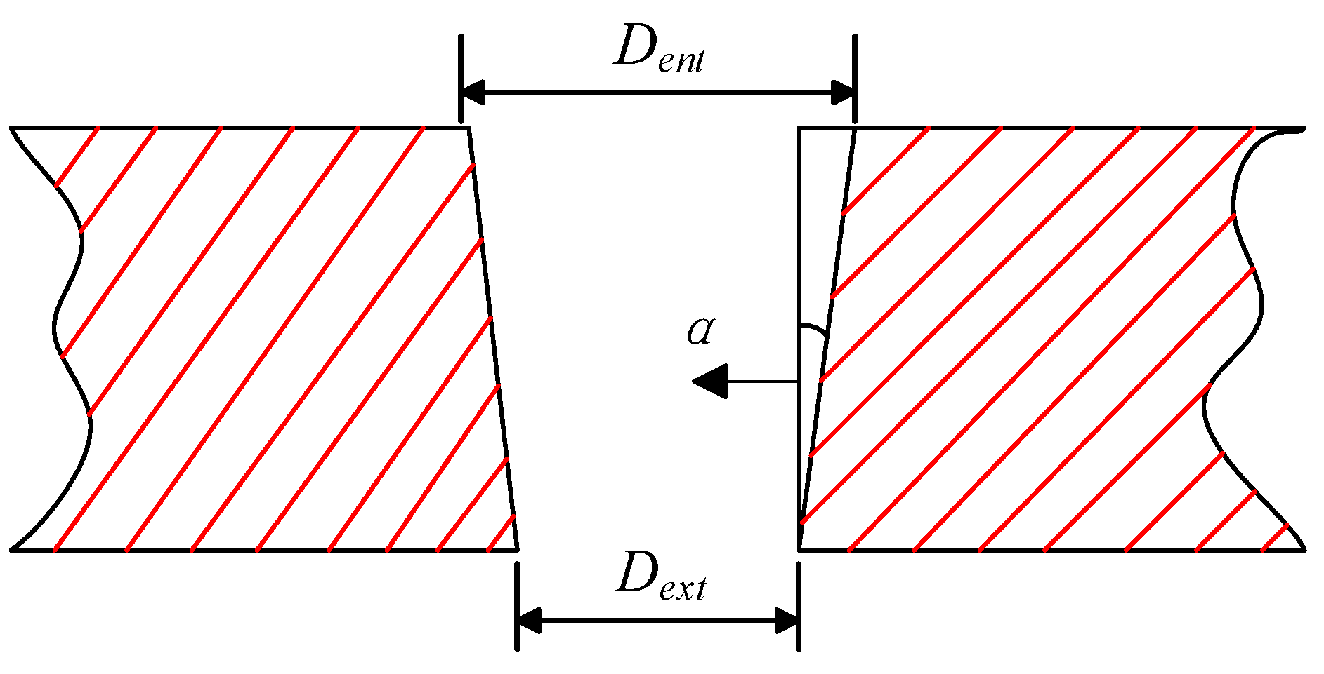
Based on the aforementioned annular scanning strategy, we investigated the influence of process parameters on machining results to determine their underlying patterns. Micro-holes were ring-cut drilled in 0.25 mm thick alumina ceramic sheets using different spot-scanning numbers, spot scanning speeds, and average powers in this experiment. The effects of these parameters on the micro-hole dimensions, taper angle, and HAZ area were investigated. Four holes were processed for each set of parameters, and the average hole dimensions were calculated for each set. As shown in Figure 3, the micro-hole taper angle measurement schematic diagram illustrates the calculation of the taper angle using Equation (1). Here, Dent (entrance diameter) represents the dimensions at the micro-hole entrance, Dext (exit diameter) is the dimensions at the micro-hole entrance exit, and h is the thickness of the alumina ceramic sheet.
α = arctan D e n t D e x t 2 h
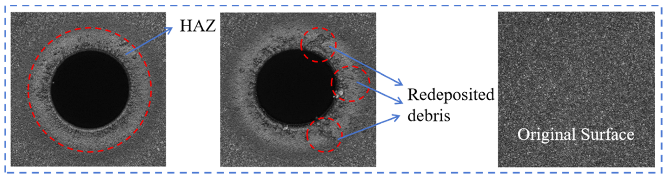
During laser drilling, the heat-affected zone (HAZ) refers to the specific region surrounding the micro-hole wall and its entry/exit edges, situated between the molten/vaporized removal zone directly affected by the laser and the base material zone unaffected by laser thermal disturbance. For crystalline α-Al2O3, this thermal exposure can lead to effects such as grain growth, recrystallization, or the initiation of microcracks—irreversible changes that modify the material’s physical and mechanical properties without significant material removal. This induces irreversible changes in the microstructure, physical properties, or mechanical properties of the material; however, no significant material removal occurs. Figure 4 illustrates the measurement of micropore heat-affected zones using confocal microscopy. The image simultaneously displays confocal scans of the redeposited debris and original surface, where the distinct color contrast between the heat-affected zone and surrounding areas is clearly discernible.
The alumina ceramic substrate selected for the experiment had a purity of 96% and a size of 50 mm × 50 mm × 0.25 mm. The properties of these materials are listed in Table 1. Before the experiment, the samples were cleaned with anhydrous ethanol for 10 min. After cleaning, the samples were placed on a precision motion stage for processing. After processing, the samples were placed in an ultrasonic cleaner for cleaning and drying. At the end of the experiment, the surface morphology of the micro-holes and their entrances and exits was observed using a confocal laser scanning microscope (Olympus OLS 4100, Olympus Corporation, Tokyo, Japan). The hole dimensions and HAZ area of the micro-holes were measured using the microscope analysis software. Energy-dispersive X-ray spectroscopy (EDS) was used to analyze the elemental composition of the micro-hole edges, surrounding areas, and substrate surfaces using a scanning electron microscope (SEM3200, Chinainstru & Quantumtec (Hefei) Co., Ltd., Hefei, China). SEM was also used to observe the microscopic morphology of the micro-hole edges, surrounding areas, and substrate surfaces.
All experiments and measurements were performed at least four times for repeatability and reliability. The results were statistically analyzed by a one-way analysis of variance (ANOVA) test using Excel. A p value of <0.05 was considered statistically significant. The ANOVA table was used to verify the extent to which the model was influenced by systematic random factors. Through ANOVA, the p-values for pore size, taper, and heat-affected zone after processing with different process parameters were all less than 0.05. The standard error of measurement ranged between 0% and 5%, indicating a minimal influence of random factors on the model analysis. The experimental results were statistically significant.
The beam intensity of the laser source exhibited a Gaussian distribution in space. The energy density F(r) at any point within the ablation zone can be calculated using the distance r between the source and focal point.
F r = F 0 e 2 r 2 / ω 0 2
where F0 represents the maximum energy density at the laser focal point, r denotes the distance between the point of interest and the focal point, and ω0 is the spot radius.
The maximum energy density at the focal point is given by Equation (3).
F 0 = 2 P 0 f π ω 0 2
where P0 represents the average laser power and ƒ denotes the laser repetition frequency.
When laser ablation removes material, the ablation threshold of the material can be expressed using Equation (4).
φ h = F 0 e D 2 2 ω 0 2
where D represents the diameter of the effective ablation zone. The relationship between D and the energy density at the laser focal point can be expressed as Equation (5).
D 2 = 2 ω 0 2 ln F 0 φ h
Combining the above expressions yields the equation shown in Equation (6).
D 2 = 2 ω 0 2 ln P 0 + ln 2 f π ω 0 2 φ h
L D = k ρ C p τ 1 2

3. Results and Discussions

3.1. Effect of the Spot-Scanning Number on Micro-Holes

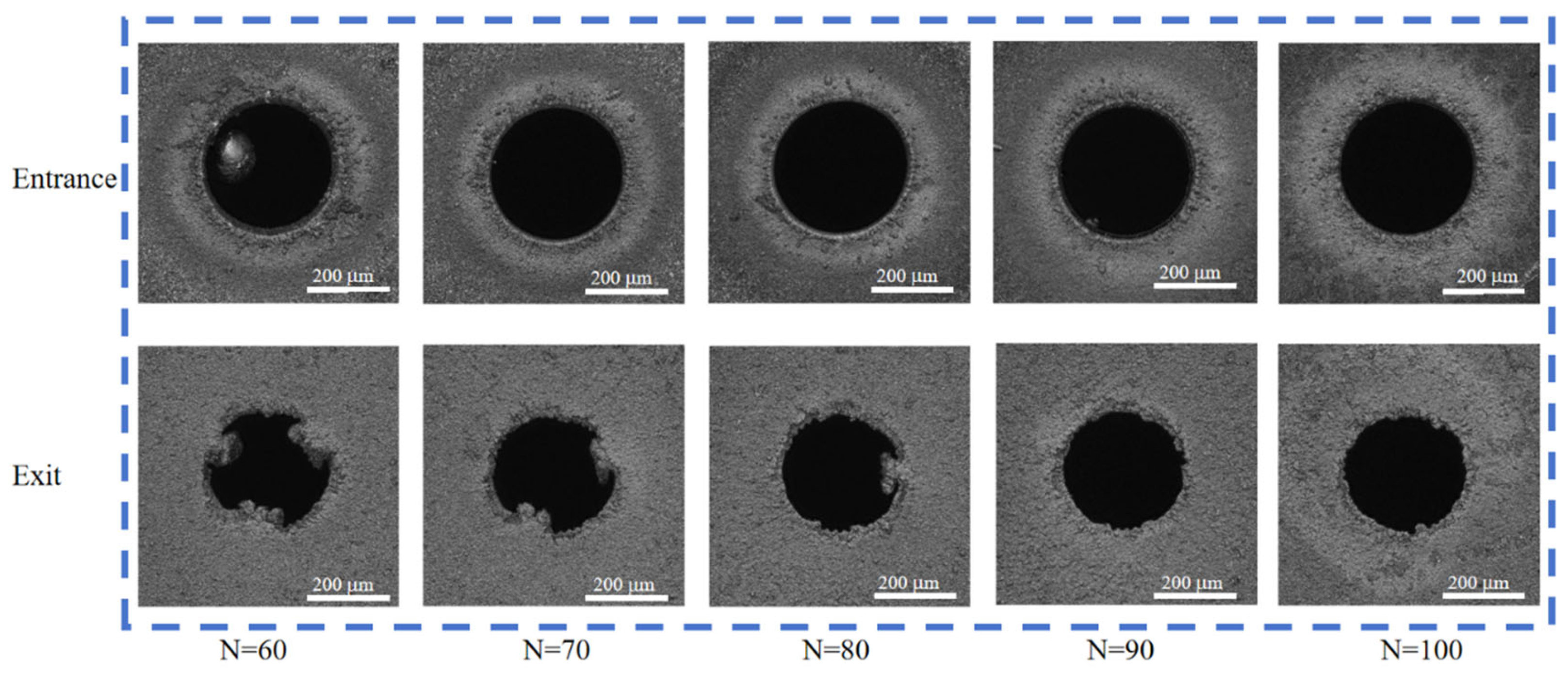
In laser processing, the “Spot-scanning number (N)” refers to the number of times the laser beam repeats the scanning along the same processing path. Specifically, denotes the number of times the laser head returns to the origin and processes along the identical trajectory after completing one full cycle. This represents the number of scans per ring. Under conditions of spot scanning speed v = 600 mm/s, repetition rate ƒ = 100 kHz and average power P = 24 W, spot-scanning numbers were set to 60, 70, 80, 90, and 100 to investigate their effect on micro-hole entrance and exit morphology. Confocal microscopy was used to observe the morphology of the micro-hole entrance and exit under different spot-scanning numbers, as shown in Figure 5. The results showed that the entrance and exit dimensions of the micro-holes gradually increased with increasing spot-scanning number; however, the spot-scanning number had a more significant effect on the micro-hole exit morphology. At 60, 70, and 80 scans, the slag remained at the micro-hole exit and decreased with increasing spot-scanning number. At 90 scans, the slag was completely removed from the micro-hole entrance, and the dimensions of the entrance and exit holes were saturated. Further increasing the spot-scanning number to 100 had little effect on the hole dimensions. Additionally, the micro-hole entrance dimensions were always larger than the exit dimensions, creating a taper angle. This was related to the laser energy attenuation within the material and the nonuniform slag discharge. The white area in the figure that is different from the surface of the substrate is the heat-affected zone. A more obvious HAZ was observed at the micro-hole entrance because of the cumulative laser energy on the material surface.
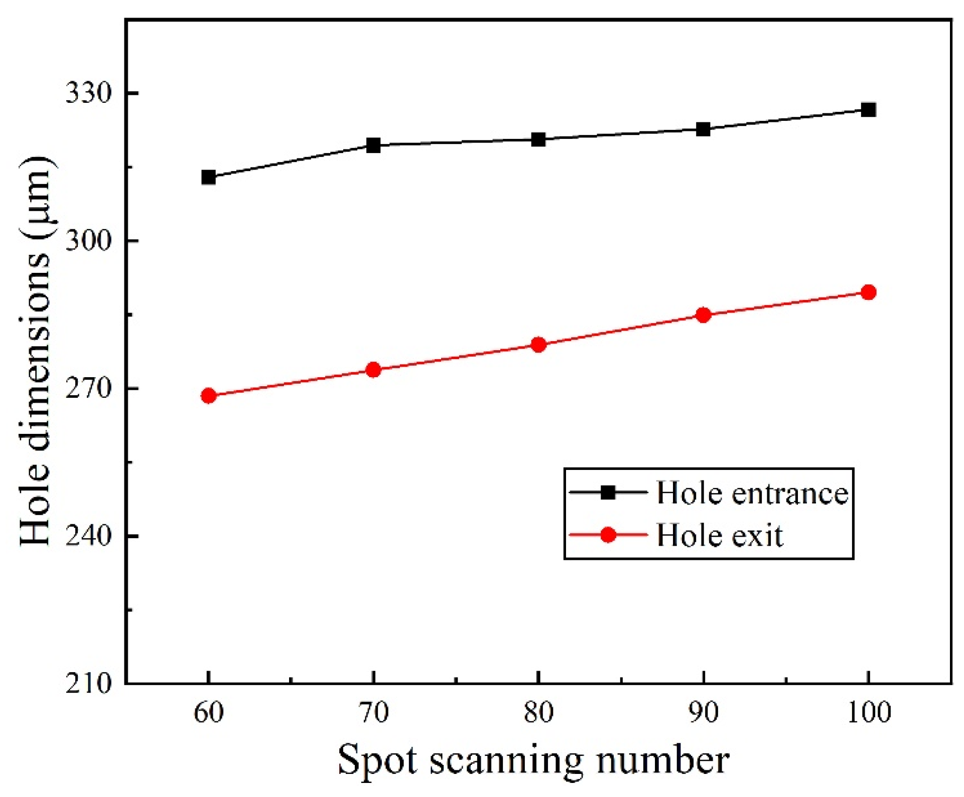
Figure 6 shows the effect of the spot-scanning number on the dimensions of the picosecond-laser ring-cut-drilled micro-holes. The results showed a significant difference between the average hole dimensions at the entrance and exit of the micro-hole. Both the entrance and exit hole dimensions increased gradually with an increasing spot scan number. This phenomenon is closely related to the laser energy deposition and material removal mechanisms. First, a specific thickness of material was removed from each laser scan. As the spot-scanning number increased, the laser energy acted on the material layer by layer, accumulating material removal and increasing the micro-hole dimension. Second, as the spot-scanning number increased, the absorbed laser energy accumulated, causing the localized temperature to increase further. This expanded the high-temperature region, melting or vaporizing more material, and further enlarging the hole dimensions. In addition, the slag was repeatedly melted and discharged during multiple scans. Each scan removed the slag and generated thermal shock to the hole wall, leading to further material removal. Notably, a higher laser energy deposition on the material surface resulted in more material removal at the entrance than at the exit, creating a taper angle with a larger entrance dimension This phenomenon was related to the laser energy attenuation within the material and the nonuniform slag discharge than the exit dimension. As the borehole depth increased, the diffraction effect of the beam within the borehole intensified, leading to an enlarged spot size and reduced energy density at the bottom of the borehole. Simultaneously, the continuously changing borehole wall geometry directly influences the beam-propagation path and energy-coupling efficiency. Furthermore, within the confined space of the borehole, the formation of plasma/plasma plumes may exert shielding, scattering, or absorption effects on subsequent pulses, further diminishing the energy reaching the borehole bottom.
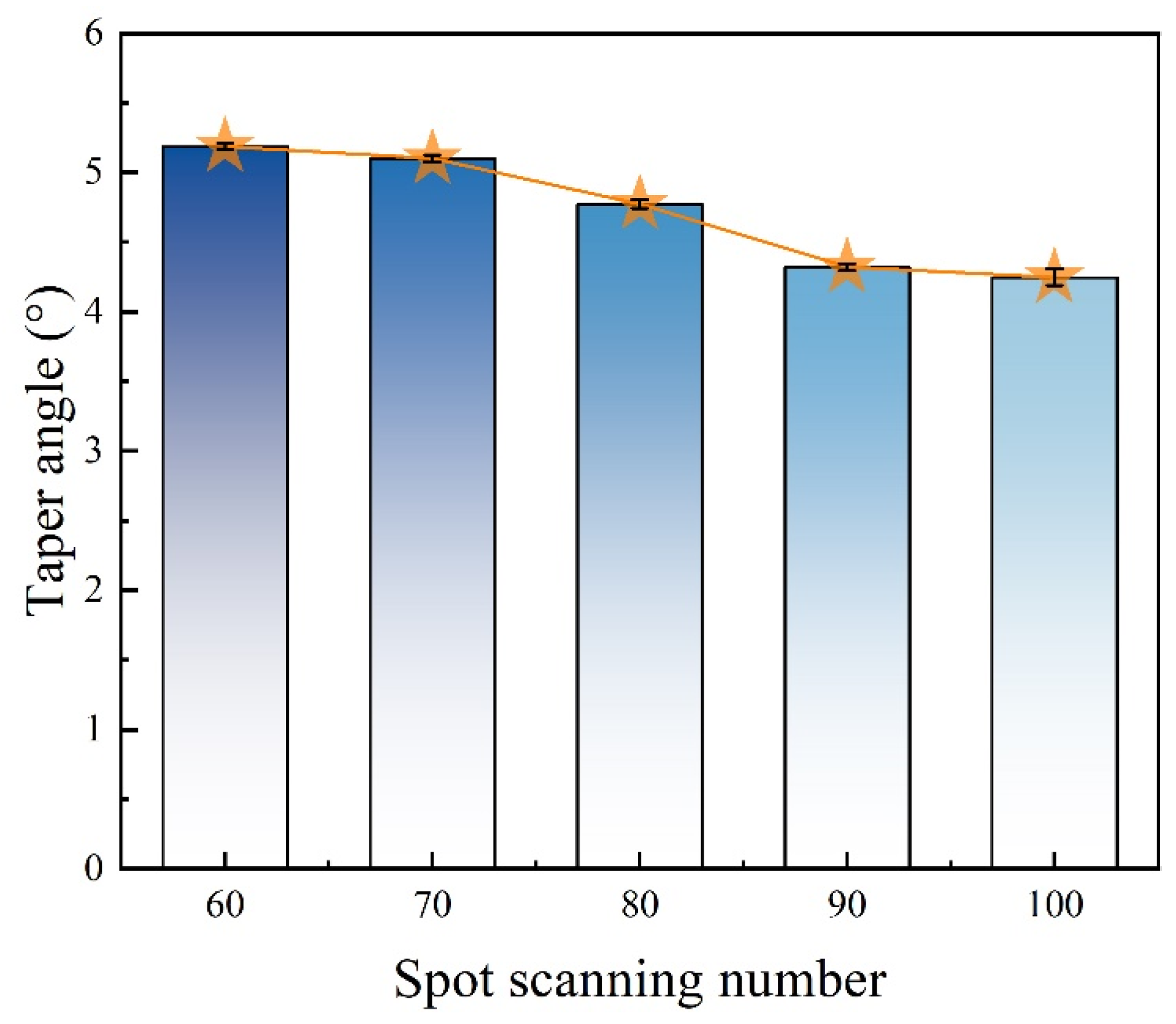
Figure 7 shows how the micro-hole taper angle changed with the spot-scanning number. The results showed that the micro-hole taper angle first decreased and then stabilized as the spot-scanning number increased. When the spot-scanning number was 60, the micro-hole taper angle increased. This was mainly because the spot-scanning number was low, and less laser energy reached the bottom of the micro-hole. This resulted in insufficient material removal at the exit, leading to a larger taper. As the spot-scanning number increased, the processed area absorbed more laser energy, resulting in more complete processing of the micro-hole entrance and exit. When the spot-scanning number reached 90, the micro-hole taper angle decreased to 4.32°. Further increases in the spot-scanning number resulted in little change in the taper angle, indicating stabilization of the microporous processing. This phenomenon can be explained by the distribution of laser energy within the material and the material removal mechanism. During the initial few scans, the laser energy was mainly concentrated on the material surface. This resulted in a larger material removal at the entrance and less energy deposition at the exit, creating a larger taper. As the spot-scanning number increased, the laser energy gradually penetrated deeper into the material, increasing the material removal at the exit and reducing the taper. Multiple scans also resulted in a more uniform distribution of the laser energy within the material. This promoted the convergence of the entrance and exit dimensions, ultimately reducing and stabilizing the taper angle.
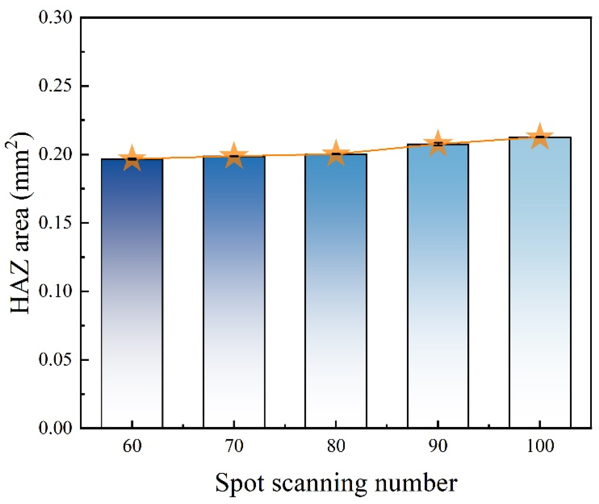
Unlike the nonlinear response of taper to scan count, the HAZ area exhibits a continuous increase with increasing scan count. Figure 8 shows how the micro-hole HAZ area varied with the spot-scanning number. The results showed that the HAZ area increased with the spot-scanning number. This was because each laser scan input a certain amount of energy into the material. As the spot-scanning number increased, the accumulated energy input increased significantly, thereby increasing the total energy absorbed by the material. Simultaneously, laser energy was deposited on the material surface and spread to the surrounding material via heat conduction. As the spot-scanning number increased, the cumulative thermal effect was enhanced, and the heat conduction range gradually expanded, thereby increasing the HAZ area.

3.2. Effect of the Spot-Scanning Speed on Micro-Holes

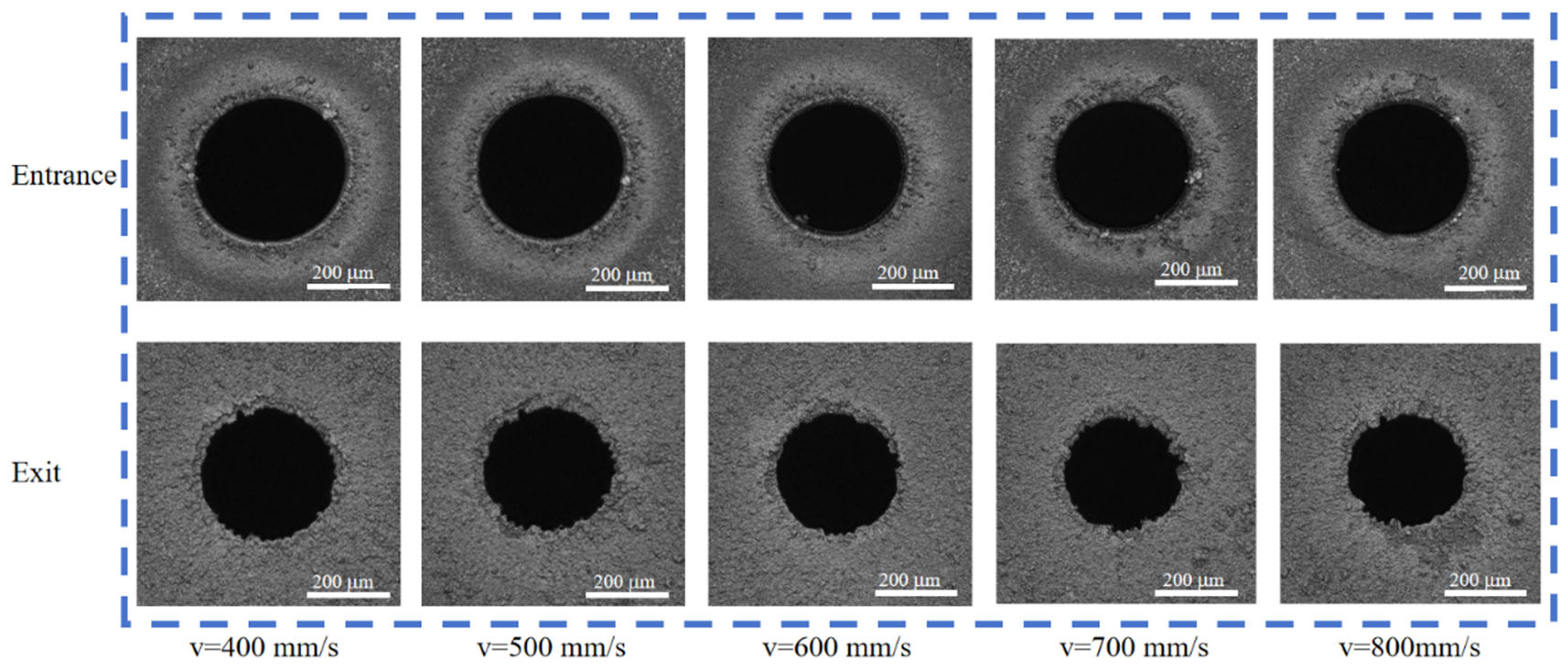
Under conditions of spot-scanning number N = 90, repetition rate ƒ =100 kHz and average power P = 24 W, spot scanning speeds were set to 400, 500, 600, 700, and 800 mm/s to investigate their effects on the entrance and exit morphology of the micro-holes. Confocal microscopy was used to observe the entrance and exit morphologies of the micro-holes at different spot-scanning speeds, as shown in Figure 9. The results showed a more obvious HAZ area at the micro-hole entrance because of the cumulative laser energy on the material surface. The HAZ area decreased with increasing spot-scanning speed. Additionally, the entrance and exit topographic qualities of the micro-holes improved with increasing spot-scanning speed. At low scanning speeds, the slag accumulated at the entrance edge, and the HAZ area was larger. At high scanning speeds, the entrance edge was smoother, slag accumulation was significantly reduced, and the HAZ was smaller.
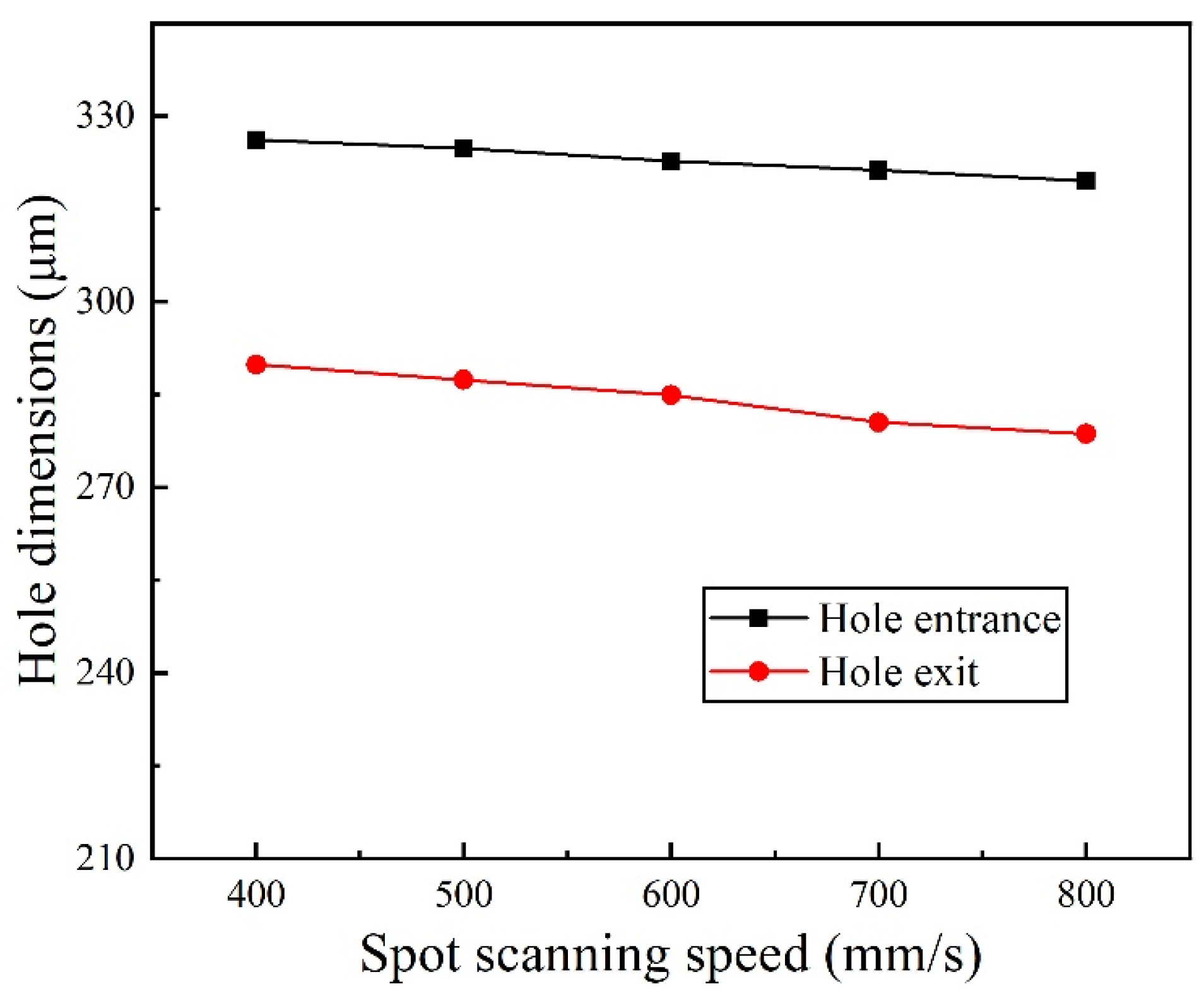
Figure 10 shows the effect of the laser scanning speed on the entrance and exit dimensions of the picosecond laser ring-cut drilled holes. The results showed a significant difference between the average dimensions at the entrance and exit of the micro-hole. Both the entrance and exit dimensions gradually decreased as the spot scanning speed increased. This occurs because a higher scanning speed reduces the dwell time of the laser beam per unit area, which lowers the total energy absorbed by the material. Consequently, the effective energy density deposited on the material surface is reduced, leading to less material removal and consequently smaller hole dimensions.
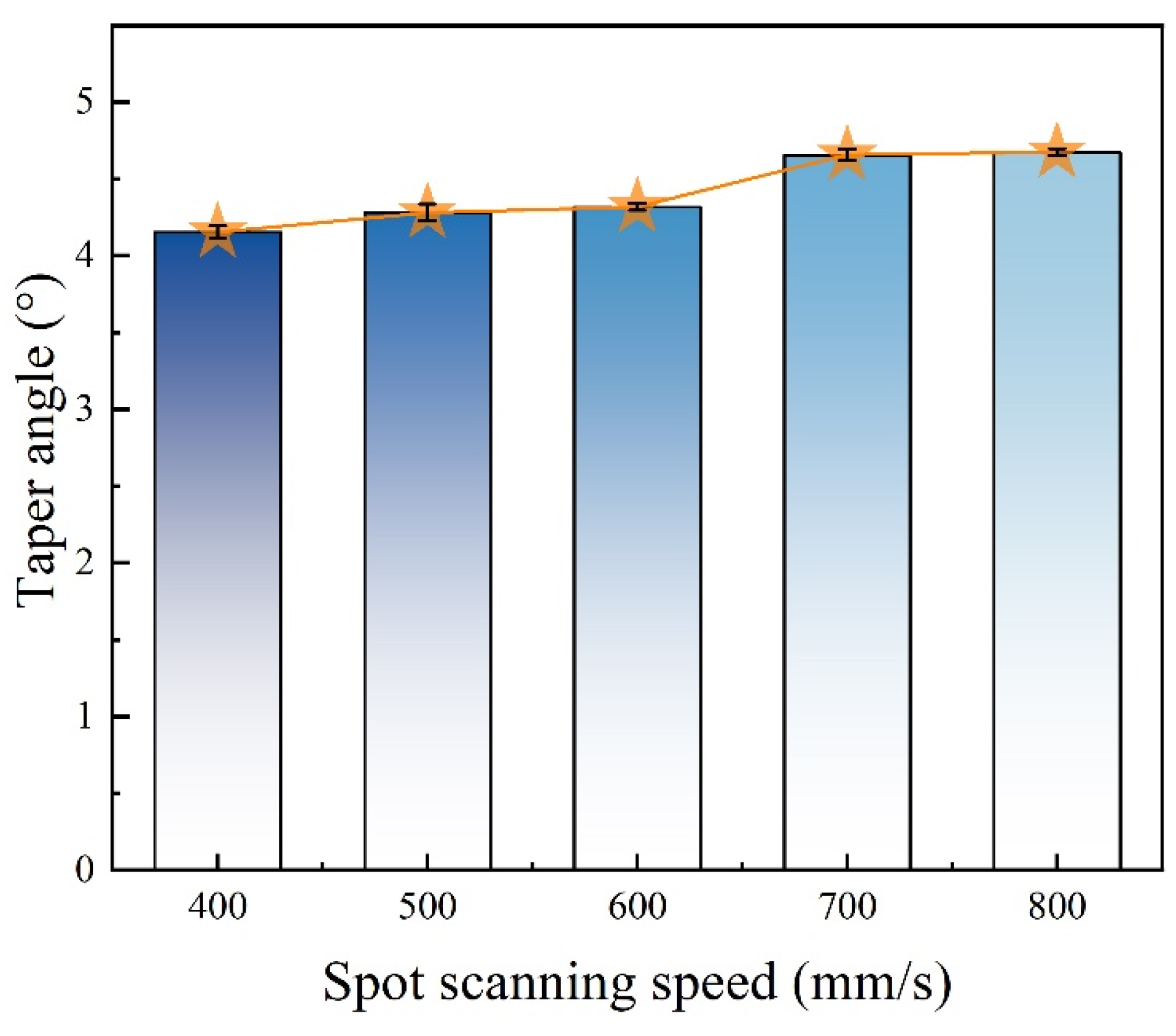
Figure 11 shows how the taper angle varied with the spot laser-scanning speed. The results showed that the taper angle gradually increased with the spot laser-scanning speed. At high scanning speeds, the dwell time of the laser beam on the unit area is shortened, reducing the energy deposition on the material surface and the energy transfer to the material interior. This inhomogeneous energy distribution resulted in more material removal at the entrance and less material removal at the exit, thereby increasing the taper angle. At a scanning speed of 400 mm/s, the taper angle was only 4.15°, indicating that ring-cut drilling significantly reduced the micro-hole taper angle. Compared to the minimum taper angle of 4.5° achieved by Ren et al. [16] using a combination of still water and flowing water to assist femtosecond laser drilling, a significant improvement has been demonstrated. However, a scanning speed that is too low reduces machining efficiency, whereas a scanning speed that is too high may degrade micro-hole quality, such as insufficient material removal at the exit or increased slag residue. Therefore, this study suggests selecting a moderate scanning speed to balance processing efficiency and microporous quality.
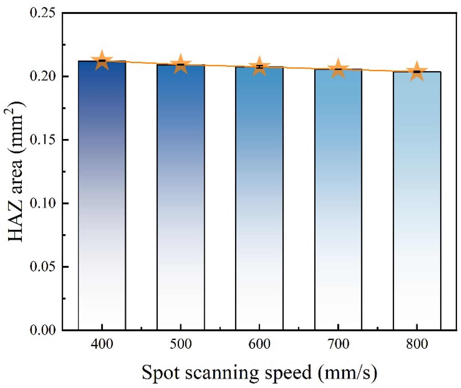
Contrary to the trend of increasing cone angle with rising scanning speed, the HAZ area gradually decreases as the scanning speed increases. Figure 12 shows how the HAZ area of the micro-holes varied with the spot-scanning speed. The results showed that the HAZ area gradually decreased as the spot-scanning speed increased. At higher scanning speeds, the dwell time of the laser beam per unit area was significantly shortened, thereby reducing the laser energy absorbed by the material. The energy density deposited on the material surface per unit time was reduced, thereby decreasing the local temperature increase and heat accumulation in the material. This led to a reduction in HAZ.

3.3. Effect of the Average Power on Micro-Holes

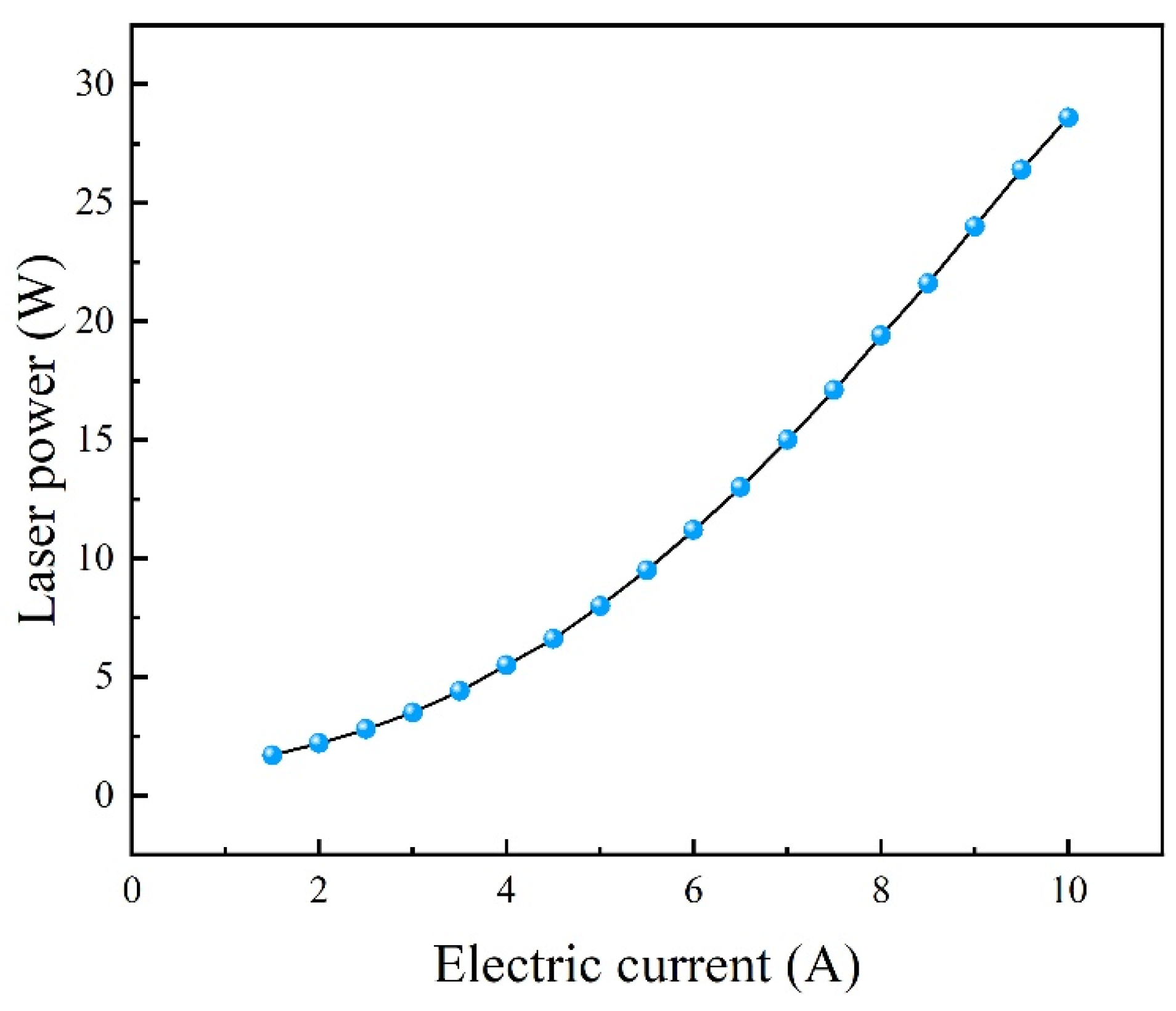
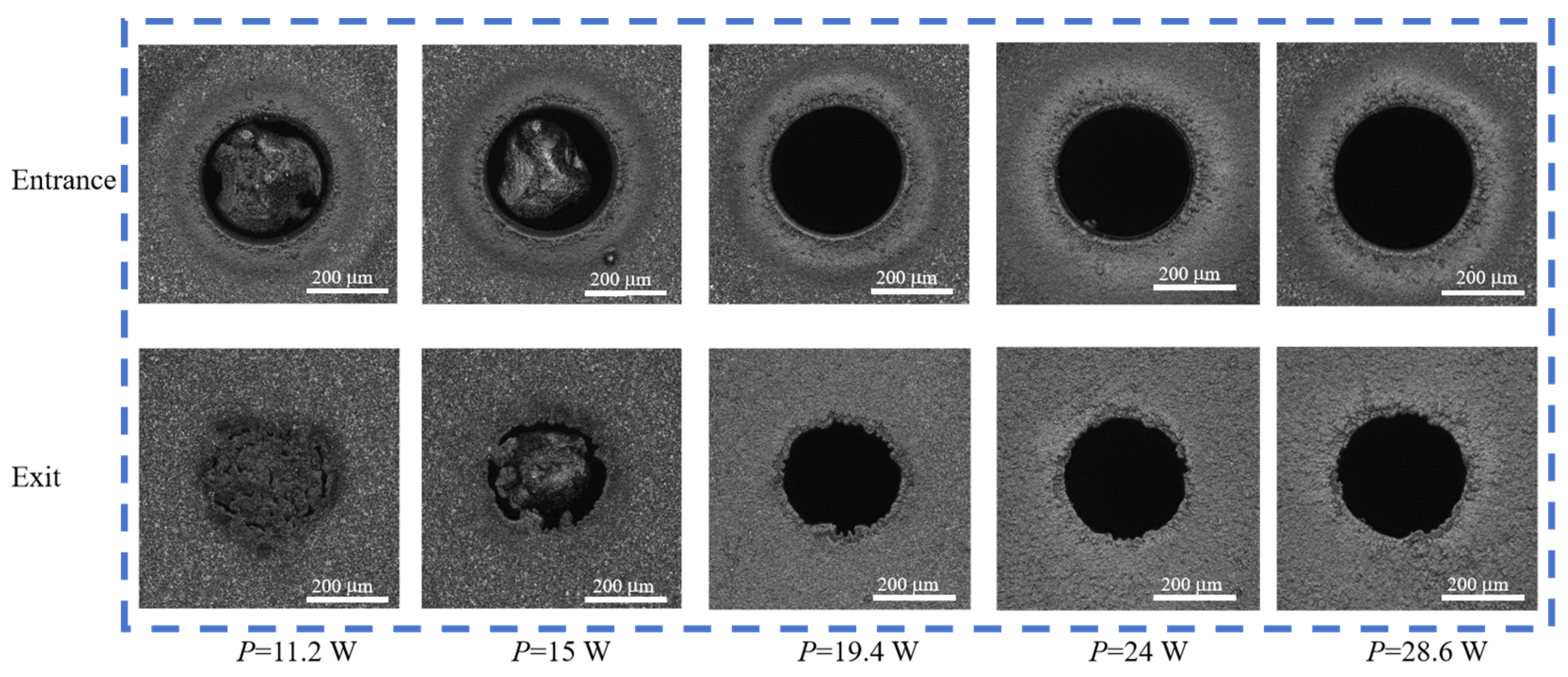
Under the conditions of spot-scanning number N = 90, repetition rate ƒ = 100 kHz and scanning speed v = 600 mm/s, the average power was set to 11.2, 15, 19.4, 24, and 28.6 W to explore its effect on the entrance and exit morphology of the micro-holes. To better characterize the relationship between the average power and perforation quality, a comparison diagram of the electric current and average power is shown in Figure 13. Confocal microscopy was used to observe the morphology of the micro-hole entrance and exit under different average powers, as shown in Figure 14. The results showed a more obvious HAZ at the micro-hole entrance because of the cumulative laser energy on the material surface. The HAZ gradually expanded as the average power increased. Specifically, at 11.2 W, a significant amount of unmelted material was present at the micro-hole entrance, whereas the exit was incompletely pierced with obvious ablation traces. When the average power was increased to 15 W, the unmelted material at the micro-hole entrance decreased significantly, and the exit partially penetrated but not completely. When the average power was further increased to 19.4 W, the unmelted material at the micro-hole entrance disappeared completely, and the exit was pierced; however, a small amount of incompletely melted material remained at the edge. When the average power reached 24 W and 28.6 W, no unremoved slag was observed at the micro-hole entrance or exit, and edge splashing was minimal. However, considering the negative influence of the HAZ on the micro-hole quality, 24 W was selected as the optimal average power parameter in this study.
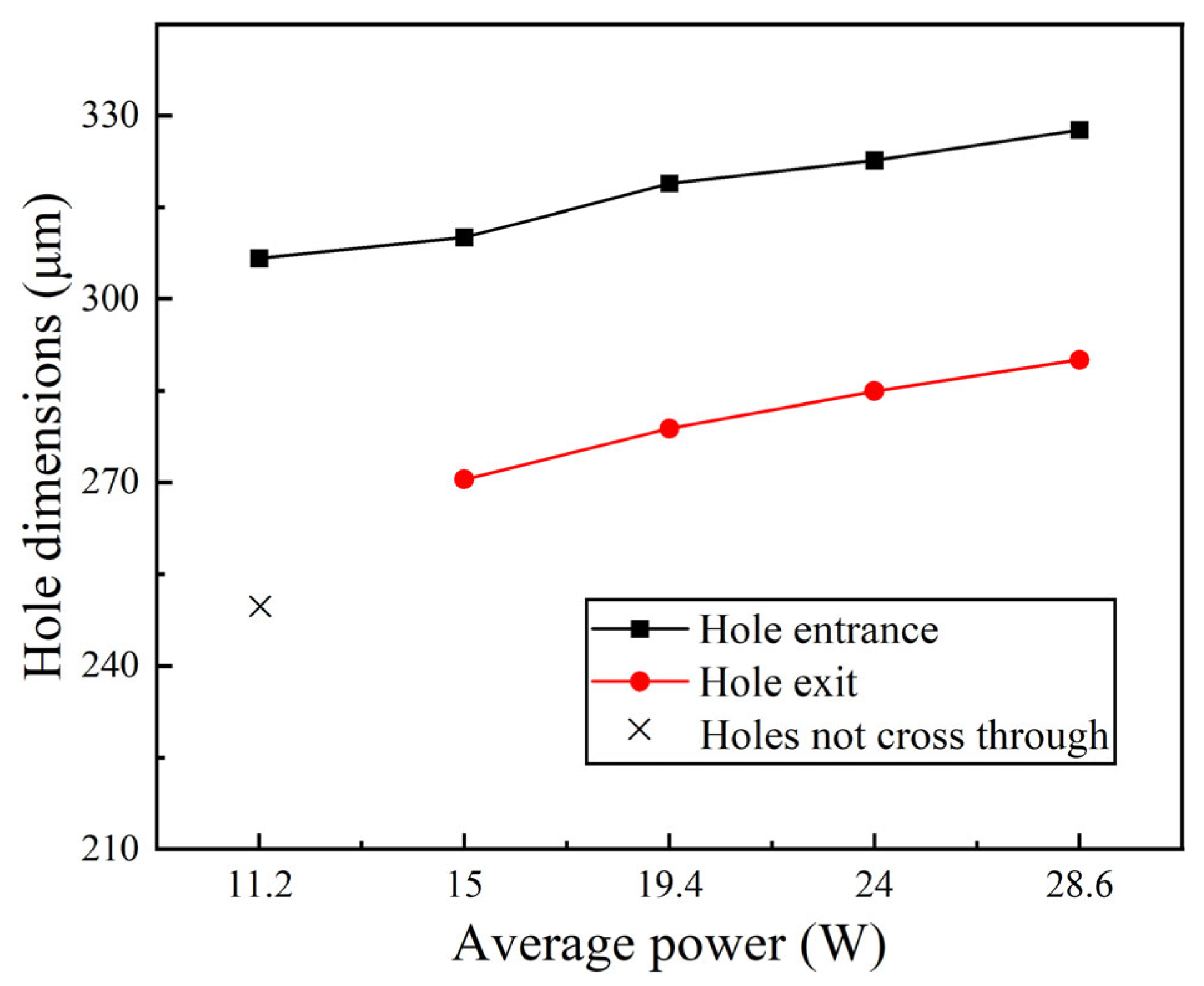
Figure 15 shows the effect of the average power on the entrance and exit dimensions of the picosecond-laser ring-cut-drilled holes. As shown in Figure 15, there was a significant difference in the average hole dimensions at the entrance and exit of the micro-hole. This is because the laser energy gradually decayed as it propagated inside the material, resulting in a higher energy density at the entrance and a lower energy density at the exit. Consequently, more material was removed at the entrance, resulting in a larger dimension, whereas less material was removed at the exit, resulting in smaller dimensions. At an average power of 11.2 W, the micro-hole did not pass through owing to the low laser energy input and insufficient energy density to fully melt or vaporize the material. However, as the average power increased, the hole dimensions at both the entrance and exit gradually increased. This was because the laser energy density increased with increasing average power. The material was melted, vaporized, and ionized more fully, resulting in a higher material removal efficiency at both the entrance and exit and an increase in the hole dimensions.
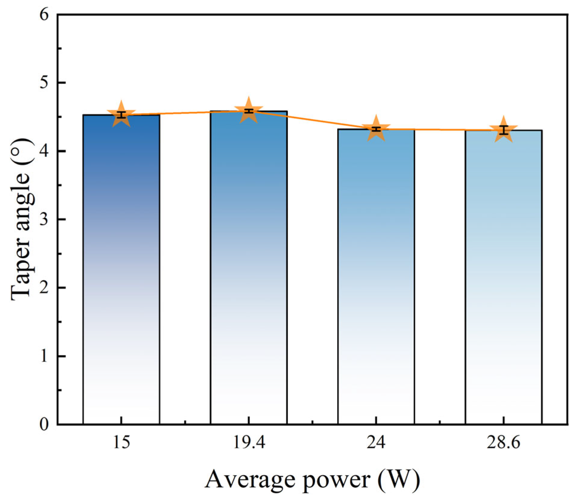
Figure 16 shows the variation in the taper angle with the average power. The results showed that in the through-hole state, the micro-hole taper angle gradually decreased with increasing average power. When the average power increased from 19.4 W to 24 W, the taper angle decreased significantly. However, when the average power increased from 24 W to 28.6 W, the decreasing trend of the taper angle was insignificant. This phenomenon is mainly related to changes in the laser energy input and material removal efficiency. When the average power was 24 W, the energy input reached a critical threshold. This led to a significant increase in the material removal efficiency and a more uniform material removal at the entrance and exit, thereby significantly reducing the taper angle. However, when the average power increased from 24 W to 28.6 W, the energy input approached saturation. The increase in the material removal efficiency was no longer significant, and thus, the taper reduction trend became less pronounced.
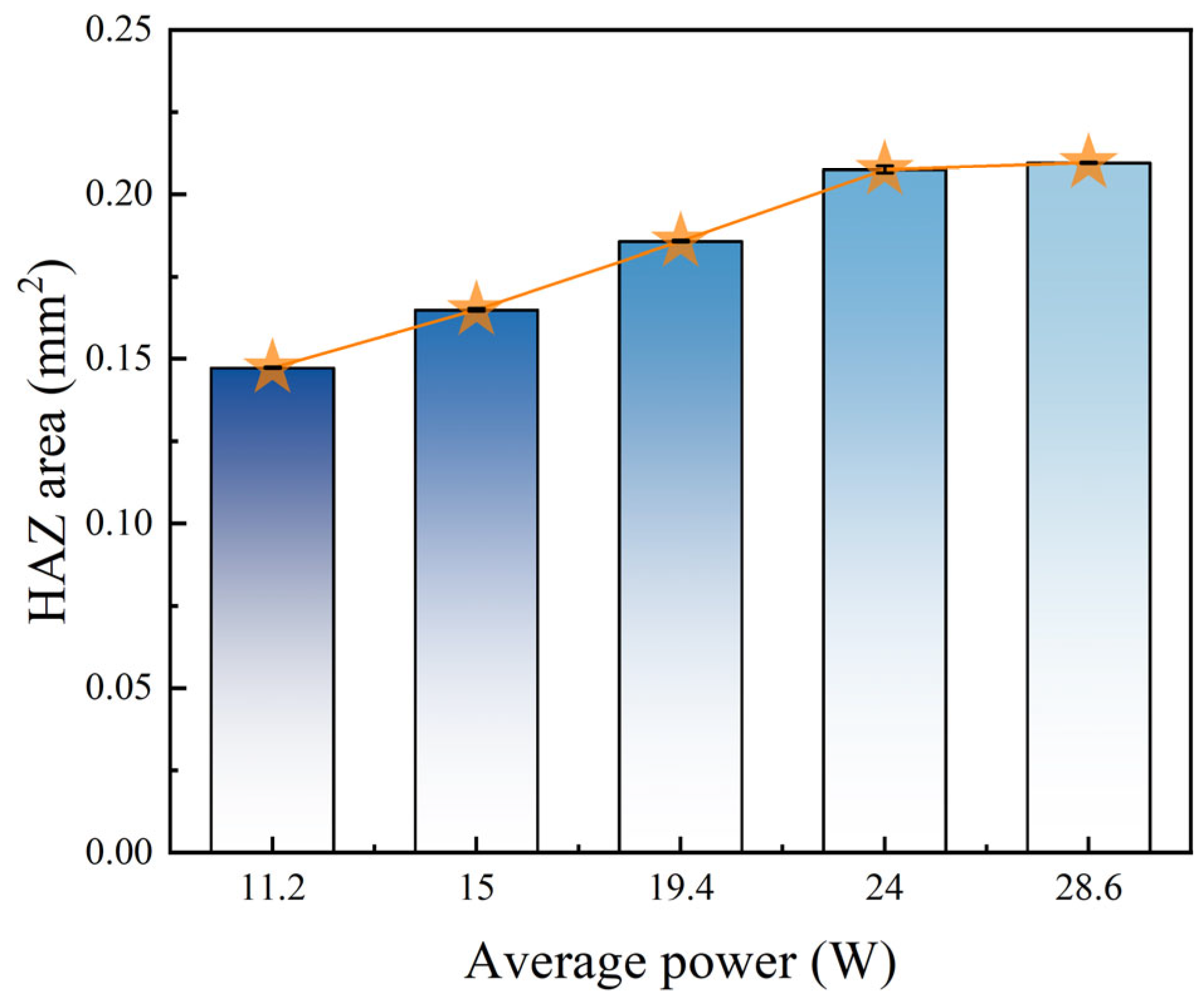
Unlike the cone angle, which first decreases significantly and then saturates as average power increases, the HAZ area exhibits a continuous increase trend with rising average power. Figure 17 shows how the micro-hole HAZ area varied with average power. The results showed that the HAZ gradually increased with increasing average power. This is because as the average power increases, the laser energy input increases significantly, thereby increasing the energy density. A higher energy density increased the energy absorbed on the material surface and inside, and enhanced the cumulative thermal effect within the material as the average power increased. More heat was spread to the surrounding material via heat conduction, thereby enlarging the HAZ.

3.4. Micro-Hole Edge and Surrounding Characterization

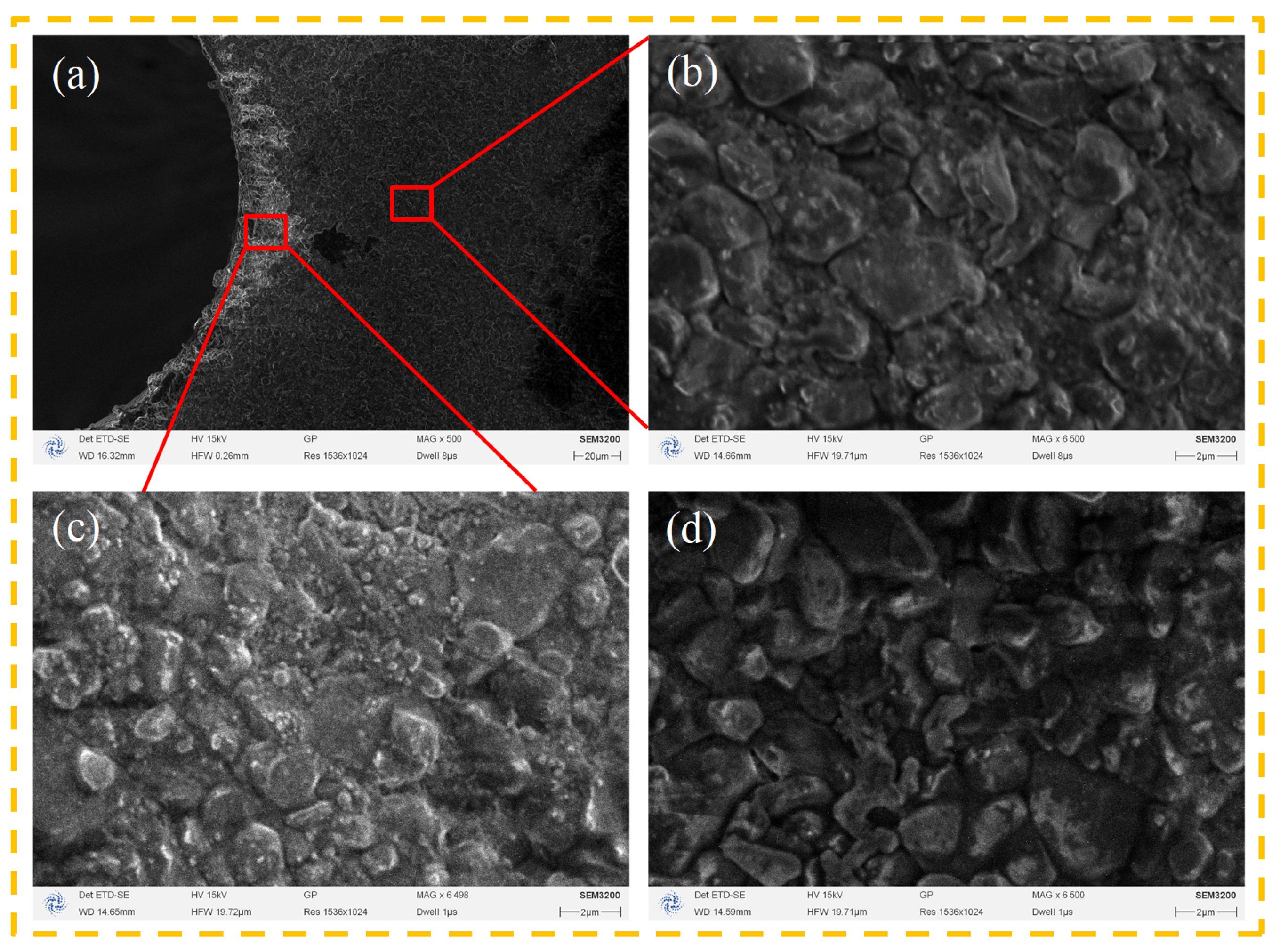
Figure 18 shows SEM images of the entrance region of micro-holes produced by picosecond laser drilling of alumina ceramics and the pristine substrate surface under the processing parameters of spot-scanning number N = 90, spot scanning speed v = 600 mm/s, and average power P = 24 W. The periphery of the holes in Figure 18a exhibits features characteristic of predominantly nonthermal ablation, such as minimal melt ejection and the absence of a continuous recast layer. This indicates that the ultrashort pulse duration of the picosecond laser (pulse width < 10 ps) effectively confines the energy deposition, thereby suppressing the formation of a significant melt and flow that typically leads to a pronounced recast layer. Alumina ceramics have an extremely high vaporization temperature, requiring localized temperatures exceeding 3700 K for material removal through drilling. Despite the relatively high thermal conductivity of alumina ceramics, the picosecond pulse duration is shorter than the characteristic time for lattice-heat diffusion. Under the action of picosecond pulsed lasers, material removal mechanisms are dominated by non-equilibrium processes induced by rapid energy deposition. This is characterized by material removal primarily through direct vaporization (sublimation), which significantly suppresses the formation of large-scale melt pools commonly observed in traditional long-pulse laser processing. However, owing to complex factors such as thermal accumulation effects between pulses and plasma shielding, localized and limited thermal melting traces may still be observed at the edges of the processing area or within the re-deposited material. Consequently, any limited molten material that may form undergoes ultra-rapid solidification, leading to distinct microstructural alterations in the vicinity of the processed area [17]. As shown in Figure 18b,c, tiny grains were present compared to the large bright grains on the original substrate surface in Figure 18d, with more tiny grains appearing closer to the edge of the hole in Figure 18c. This is because the high energy density of the picosecond laser causes instantaneous vaporization or melting of the material being irradiated. However, at very short pulse durations, the heat does not have time to diffuse into the surrounding area, creating a cycle of rapid melting and solidification. This nonequilibrium cooling promoted the formation of small micron-sized grains on the surface of the material.
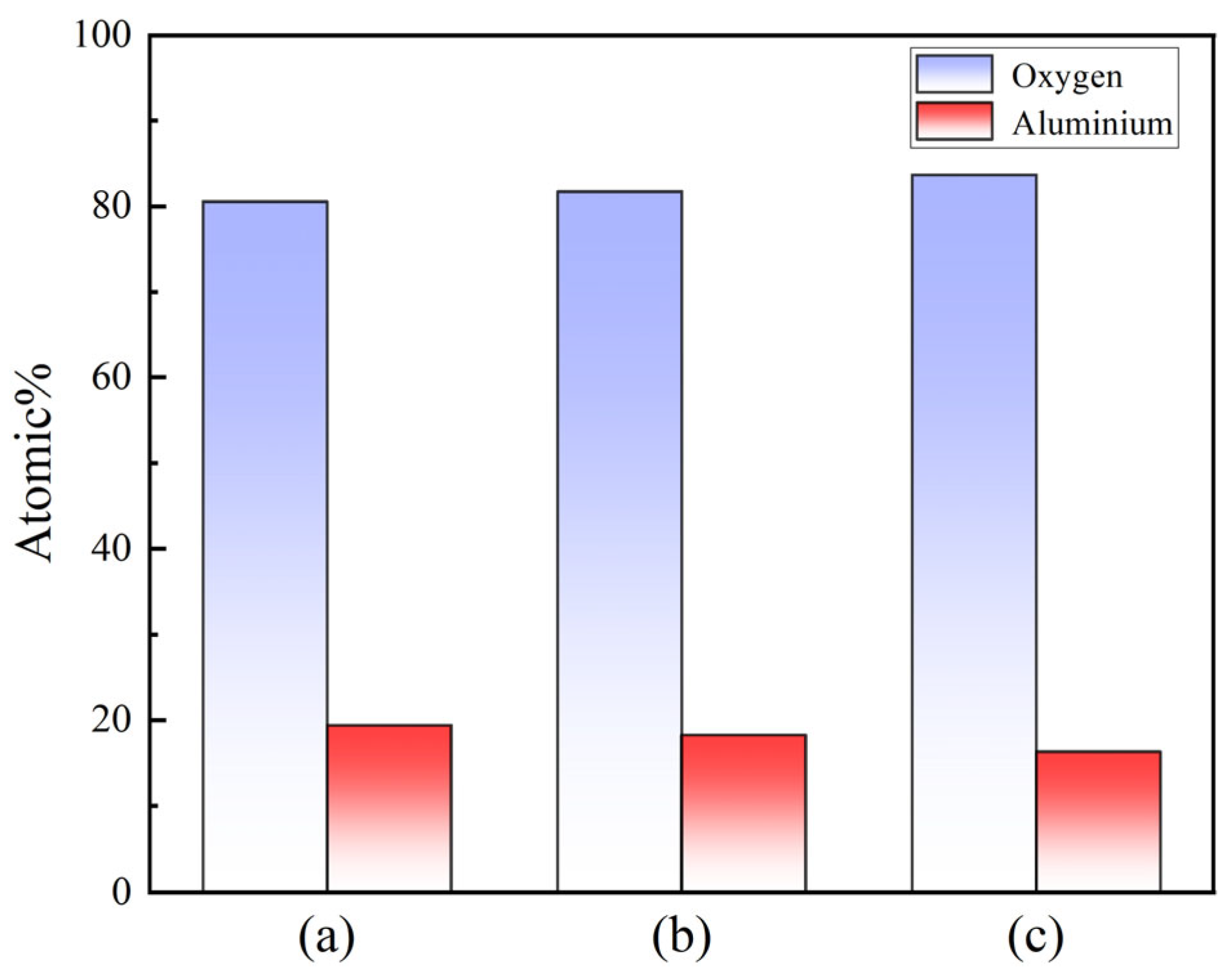
Figure 19 shows the EDS images of the (a) micro-hole edge, (b) HAZ area near the micro-hole, and (c) substrate surface after picosecond laser drilling. Table 2 presents the results of quantitative EDS results of the (a) micro-hole edge, (b) HAZ area near the micro-hole, and (c) substrate surface after picosecond laser drilling. The atomic contents of O and Al at the micro-hole edge were 80.61% and 19.39%, respectively, under the processing parameters: spot-scanning number N = 90, spot scanning speed v = 600 mm/s, and average power P = 24 W. The atomic contents of O and Al in the HAZ area near the micro-hole were 81.72% and 18.28%, respectively, as analyzed by EDS. The atomic contents of O and Al on the substrate surface were 83.68% and 16.32%, respectively. Compared with the alumina ceramic substrate surface, the HAZ area at the micro-hole edges and the surrounding area showed decreased O and increased Al atomic content. This occurs because multiple scans of the picosecond laser partially decompose the aluminum oxide into aluminum and oxygen. Oxygen is more likely to escape as a gas at high temperatures, whereas aluminum has a higher boiling point, leading to more aluminum remaining or recombining. This resulted in a decreased oxygen atom percentage and relative aluminum atom enrichment at the micro-hole edges and surrounding area.

4. Conclusions

In this study, a novel picosecond laser ring-cut drilling method was employed to drill holes in alumina ceramics. The morphology, dimensions, taper angle, and HAZ area of the resulting holes were investigated using different laser processing parameters. The effects of spot-scanning number, spot-scanning speed, and average power on the micro-holes were also theoretically analyzed. The results showed that picosecond laser ring-cut drilling significantly improved the drilling efficiency and hole quality, yielding micro-holes with smaller tapers and heat-affected zone (HAZ) areas. The main findings of this study are as follows:
(1)
As the spot-scanning number increased, the hole dimensions at the entrance and exit of the micro-hole and HAZ area gradually increased. However, the taper angle initially decreased and then stabilized as the spot-scanning number increased. When the spot-scanning number was low, slag remained at the micro-hole exit. However, as the spot-scanning number increased, the amount of slag residue gradually decreased.
(2)
As the spot scanning speed increased, the hole dimensions at the entrance and exit of the micro-hole and the heat-affected zone (HAZ) area gradually decreased, whereas the micro-hole taper angle gradually increased. When the spot-scanning speed was low, the slag accumulated at the entrance edge. When the spot-scanning speed was high, the entrance edge was smoother, and the slag accumulation was significantly reduced.
(3)
As the average power increased, the dimensions of the micro-hole at the entrance and exit and the HAZ area gradually increased, whereas the micro-hole taper angle decreased. When the average power was 11.2 W, there was an obvious unmelted material at the micro-hole entrance, and the exit was not completely pierced, with obvious ablation traces. The average power significantly affected the ability of laser drilling to penetrate the holes.
(4)
Considering both processing efficiency and quality, the optimal parameters were selected as follows: spot-scanning number N = 90, spot scanning speed v = 600 mm/s, and average power P = 24 W. Under these conditions, micro-holes with a taper angle α = 4.32° and a heat-affected zone (HAZ) area of approximately 0.207 mm2 were obtained. Tiny grains were found around the micro-hole area, which differed from the large clean grains on the original substrate surface. Compared to the original substrate surface, the percentage of oxygen atoms decreased, whereas the percentage of aluminum atoms increased at the micro-hole edge and HAZ surface.
Based on these results, picosecond laser ring-cut drilling of ceramic materials is not only efficient, but also improves drilling quality through controlled processing parameters, offering significant application value in ceramic material processing. Concurrently, EDS-based compositional analysis primarily revealed macroscopic trends in elemental distribution. To elucidate the laser-induced changes in the surface chemical states, future studies should employ X-ray photoelectron spectroscopy (XPS), which is sensitive to elemental chemical states, for in-depth analysis.

Author Contributions

W.Z.: Conceptualization, Formal analysis, Validation, Data curation, Visualization, Writing—original draft. L.Y.: Funding acquisition, Methodology, Software, Investigation, Writing—review and editing. X.Z.: Conceptualization, Resources, Supervision, Writing—review and editing. S.C.: Visualization, Writing—review and editing. P.L.: Software, Validation. All authors have read and agreed to the published version of the manuscript.

Funding

This work was financially supported by (1) the National Natural Science Foundation of China (No.52375470), (2) the Central Guidance on Local Science and Technology Development Fund of Shanxi Province (Grant No. YDZJSX2022C005), and (3) the Shanxi Provincial Key Research and Development Project (No. 202302030201004).

Data Availability Statement

Data will be made available upon reasonable request.

Conflicts of Interest

The authors declare that they have no known competing financial interests or personal relationships that could have appeared to influence the work reported in this paper.

References

  1. Liang, C.; Li, Z.; Wang, C.; Li, K.; Xiang, Y.; Jia, X.S. Laser drilling of alumina ceramic substrates: A review. Opt. Laser Technol. 2023, 167, 109828. [Google Scholar] [CrossRef]
  2. Penilla, E.H.; Devia-Cruz, L.F.; Wieg, A.T.; Martinez-Torres, P.; Cuando-Espitia, N.; Sellappan, P.; Kodera, Y.; Aguilar, G.; Garay, J.E. Ultrafast laser welding of ceramics. Science 2019, 365, 803–808. [Google Scholar] [CrossRef] [PubMed]
  3. Xiao, Z.H.; Yu, S.J.; Li, Y.M.; Ruan, S.C.; Kong, L.B.; Huang, Q.; Huang, Z.R.; Zhou, K.; Su, H.B.; Yao, Z.J.; et al. Materials development and potential applications of transparent ceramics: A review. Mater. Sci. Eng. R Rep. 2020, 139, 100518. [Google Scholar] [CrossRef]
  4. Kim, H.B.; Park, E.D. Ammonia decomposition over Ru catalysts supported on alumina with different crystalline phases. Catal. Today 2023, 411, 113817. [Google Scholar] [CrossRef]
  5. Jia, X.S.; Chen, Y.Q.; Liu, L.; Wang, C.; Duan, J.A. Advances in Laser Drilling of Structural Ceramics. Nanomaterials 2022, 12, 230. [Google Scholar] [CrossRef]
  6. Wang, H.J.; Lin, H.T.; Wang, C.Y.; Zheng, L.J.; Hu, X.Y. Laser drilling of structural ceramics-A review. J. Eur. Ceram. Soc. 2017, 37, 1157–1173. [Google Scholar] [CrossRef]
  7. Liu, Z.; Zhang, H.; Yan, Y.; Wu, H.; Yang, B.; Li, Y.; Liu, X.; Luo, H.; Huang, Z. Corrosion of sintered SiC ceramics in mixed acid solution: Temperature and time dependences. Corros. Eng. Sci. Technol. 2017, 52, 38–45. [Google Scholar] [CrossRef]
  8. Basar, G.; Kahraman, F.; Der, O. Multi-Response Optimization of Drilling Parameters in Direct Hot-Pressed Al/B4C/SiC Hybrid Composites Using Taguchi-Based Entropy-CoCoSo Method. Materials 2025, 18, 4319. [Google Scholar] [CrossRef]
  9. Yalçin, B.; Bolat, C.; Ergene, B.; Karakilinç, U.; Yavas, Ç.; Öz, Y.; Ercetin, A.; Maras, S.; Der, O. Effect of Drilling Parameters and Tool Diameter on Delamination and Thrust Force in the Drilling of High-Performance Glass/Epoxy Composites for Aerospace Structures with a New Design Drill. Polymers 2024, 16, 3011. [Google Scholar] [CrossRef]
  10. Zhao, W.Q.; Mei, X.S.; Wang, L.Z. Competitive mechanism of laser energy and pulses on holes ablation by femtosecond laser percussion drilling on AlN ceramics. Ceram. Int. 2022, 48, 36297–36304. [Google Scholar] [CrossRef]
  11. Chen, Y.; Zhou, Q.; Fan, J.T.; Zhao, Y.A.; Jiang, B.X.; Zhang, L. Study on the effect of size and density of micropores on transparent ceramic damage induced under intense laser irradiation. J. Mater. Res. Technol. 2024, 31, 772–786. [Google Scholar] [CrossRef]
  12. Qiao, Y.Q.; Chen, T.T.; Ma, H.R.; Liu, Y.; Tang, A.G.; Xiong, W.; Deng, L.M. Experimental study on the sidewall quality of femtosecond laser drilling CFRP. Compos. Part B-Eng. 2023, 266, 110972. [Google Scholar] [CrossRef]
  13. Jia, X.S.; Lin, J.W.; Li, Z.; Wang, C.A.N.; Li, K.; Wang, C.; Duan, J.A. Continuous wave laser ablation of alumina ceramics under long focusing condition. J. Manuf. Process. 2025, 134, 530–546. [Google Scholar] [CrossRef]
  14. Radhakrishnan, J.; Marimuthu, S. Machining of Ox-Ox (Al2O3/Al2O3) ceramics matrix composites by ultrafast laser. Ceram. Int. 2024, 50, 39678–39686. [Google Scholar] [CrossRef]
  15. Li, Z.; Lin, J.W.; Jia, X.S.; Li, X.; Li, K.; Wang, C.; Sun, K.; Ma, Z.; Duan, J.A. High efficiency femtosecond laser ablation of alumina ceramics under the filament induced plasma shock wave. Ceram. Int. 2024, 50, 47472–47484. [Google Scholar] [CrossRef]
  16. Ren, N.F.; Zhang, J.; Li, Z.; Qi, D.H.; Zhang, H.M.; Xia, K.B. The Effects of Static- and Flowing-Water-Assisted Methods on the Quality of Femtosecond Laser Drilling of Thermal-Barrier-Coated Superalloys. Metals 2025, 15, 261. [Google Scholar] [CrossRef]
  17. Malinauskas, M.; Zukauskas, A.; Hasegawa, S.; Hayasaki, Y.; Mizeikis, V.; Buividas, R.; Juodkazis, S. Ultrafast laser processing of materials: From science to industry. Light Sci. Appl. 2016, 5, e16133. [Google Scholar] [CrossRef]
  18. Kacar, E.; Mutlu, M.; Akman, E.; Demir, A.; Candan, L.; Canel, T.; Gunay, V.; Sinmazcelik, T. Characterization of the drilling alumina ceramic using Nd:YAG pulsed laser. J. Mater. Process. Technol. 2009, 209, 2008–2014. [Google Scholar] [CrossRef]
  19. Hanon, M.M.; Akman, E.; Oztoprak, B.G.; Gunes, M.; Taha, Z.A.; Hajim, K.I.; Kacar, E.; Gundogdu, O.; Demir, A. Experimental and theoretical investigation of the drilling of alumina ceramic using Nd:YAG pulsed laser. Opt. Laser Technol. 2012, 44, 913–922. [Google Scholar] [CrossRef]
  20. Yan, Y.Z.; Ji, L.F.; Bao, Y.; Jiang, Y.J. An experimental and numerical study on laser percussion drilling of thick-section alumina. J. Mater. Process. Technol. 2012, 212, 1257–1270. [Google Scholar] [CrossRef]
  21. Bharatish, A.; Murthy, H.N.N.; Aditya, G.; Anand, B.; Satyanarayana, B.S.; Krishna, M. Evaluation of thermal residual stresses in laser drilled alumina ceramics using Micro-Raman spectroscopy and COMSOL Multiphysics. Opt. Laser Technol. 2015, 70, 76–84. [Google Scholar] [CrossRef]
  22. Shaheen, M.E.; Gagnon, J.E.; Fryer, B.J. Experimental studies on ablation characteristics of alumina after irradiation with a 193-nm ArF excimer laser. Eur. Phys. J. Plus 2021, 136, 119. [Google Scholar] [CrossRef]
  23. Krstulovic, N.; Milosevic, S. Drilling enhancement by nanosecond-nanosecond collinear dual-pulse laser ablation of titanium in vacuum. Appl. Surf. Sci. 2010, 256, 4142–4148. [Google Scholar] [CrossRef]
  24. Wang, H.J.; Chen, Q.; Lin, D.T.; Zuo, F.; Zhao, Z.X.; Wang, C.Y.; Lin, H.T. Effect of scanning pitch on nanosecond laser micro-drilling of silicon nitride ceramic. Ceram. Int. 2018, 44, 14925–14928. [Google Scholar] [CrossRef]
  25. Li, Z.Z.; Fan, H.; Wang, L.; Zhang, X.; Zhao, X.J.; Yu, Y.H.; Xu, Y.S.; Wang, Y.; Wang, X.J.; Juodkazis, S.; et al. Super-stealth dicing of transparent solids with nanometric precision. Nat. Photonics 2024, 18, 799–808. [Google Scholar] [CrossRef]
  26. Li, J.; Zhong, S.; Huang, J.X.; Qiu, P.; Wang, P.; Li, H.; Qin, C.; Miao, D.; Xu, S.L. Laser-guided anisotropic etching for precision machining of micro-engineered glass components. Int. J. Mach. Tools Manuf. 2024, 198, 104152. [Google Scholar] [CrossRef]
  27. Amsellem, W.; Sarvestani, H.Y.; Pankov, V.; Martinez-Rubi, Y.; Gholipour, J.; Ashrafi, B. Deep precision machining of SiC ceramics by picosecond laser ablation. Ceram. Int. 2023, 49, 9592–9606. [Google Scholar] [CrossRef]
  28. Li, C.D.; Lee, S.; Nikumb, S. Femtosecond Laser Drilling of Alumina Wafers. J. Electron. Mater. 2009, 38, 2006–2012. [Google Scholar] [CrossRef]
  29. Ren, N.F.; Xia, K.B.; Yang, H.Y.; Gao, F.Q.; Song, S.W. Water-assisted femtosecond laser drilling of alumina ceramics. Ceram. Int. 2009, 47, 11465–11473. [Google Scholar] [CrossRef]
  30. Wang, J.S.; Fang, F.Z.; An, H.J.; Wu, S.; Qi, H.M.; Cai, Y.X.; Guo, G.Y. Laser machining fundamentals: Micro, nano, atomic and close-to-atomic scales. Int. J. Mach. Tools Manuf. 2023, 5, 012005. [Google Scholar] [CrossRef]
  31. Obata, K.; Caballero-Lucas, F.; Kawabata, S.; Miyaji, G.; Sugioka, K. GHz bursts in MHz burst (BiBurst) enabling high-speed femtosecond laser ablation of silicon due to prevention of air ionization. Int. J. Mach. Tools Manuf. 2023, 5, 025002. [Google Scholar] [CrossRef]
  32. Beausoleil, C.; Sarvestani, H.Y.; Katz, Z.; Gholipour, J.; Ashrafi, B. Deep and high precision cutting of alumina ceramics by picosecond laser. Ceram. Int. 2020, 46, 15285–15296. [Google Scholar] [CrossRef]
  33. Saini, S.K.; Dubey, A.K. Study of material characteristics in laser trepan drilling of ZTA. J. Manuf. Process. 2019, 44, 349–358. [Google Scholar] [CrossRef]
  34. Li, M.; Wen, Z.X.; Wang, P.; Li, Z.W.; Lu, G.X.; Liu, Y.X.; Yue, Z.F. Size effect of femtosecond laser helical drilling on nickel-based single crystal superalloy. J. Manuf. Process. 2024, 116, 77–91. [Google Scholar] [CrossRef]
  35. Sun, T.; Fan, Z.J.; Sun, X.M.; Ji, Y.C.; Zhao, W.Q.; Cui, J.L.; Mei, X.S. Femtosecond laser drilling of film cooling holes: Quantitative analysis and real-time monitoring. J. Manuf. Process. 2023, 101, 990–998. [Google Scholar] [CrossRef]
  36. Liu, C.; Li, C.; Gao, L.; Shen, R.F. Micro-hole drilling of 2.5D C/SiC composite with picosecond laser: Numerical modeling and experimental validation on hole shape evolution. J. Manuf. Process. 2022, 81, 852–864. [Google Scholar] [CrossRef]
  37. Li, J.Y.; Ding, Y.; Ge, C.C.; Sun, X.Y.; Yang, L.J.; Wang, Y.; Zhang, W.; Lu, Y.Q. Investigations on 355 nm picosecond laser machining of carbon fiber reinforced polymer composites. J. Manuf. Process. 2023, 101, 854–866. [Google Scholar] [CrossRef]
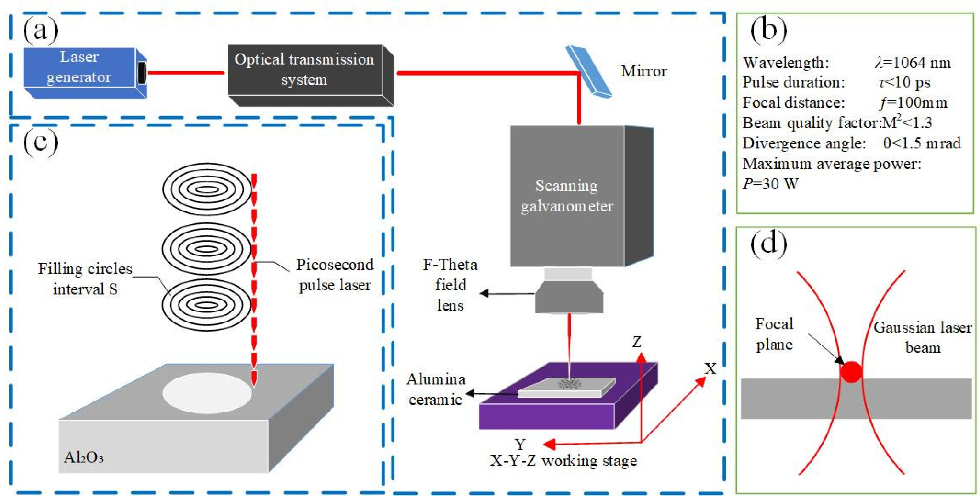
Figure 1. (a) Picosecond laser processing system; (b) specific parameters; (c) laser ring-cut drilling technology; (d) schematic diagram of laser focusing plane.
Machines 14 00180 g001
Figure 2. (a) Single-pulse laser drilling methods; (b) multi-pulse laser drilling methods.
Machines 14 00180 g002
Figure 3. Schematic diagram of taper angle measurement.
Machines 14 00180 g003
Figure 4. Schematic diagram of HAZ area measurement and observations of the redeposited debris and original surface.
Machines 14 00180 g004
Figure 5. Entrance and exit morphologies of the micro-holes drilled at different spot-scanning numbers.
Machines 14 00180 g005
Figure 6. Effect of spot-scanning number on the entrance and exit dimensions of the micro-holes.
Machines 14 00180 g006
Figure 7. Effect of spot-scanning number on the taper angle of the micro-holes.
Machines 14 00180 g007
Figure 8. Effect of spot-scanning number on the HAZ area of the micro-holes.
Machines 14 00180 g008
Figure 9. Entrance and exit morphologies of the micro-holes drilled at different spot scanning speeds.
Machines 14 00180 g009
Figure 10. Effect of spot scanning speed on the entrance and exit dimensions of the micro-holes.
Machines 14 00180 g010
Figure 11. Effect of spot scanning speed on the taper angle of the micro-holes.
Machines 14 00180 g011
Figure 12. Effect of spot scanning speed on the HAZ area of the micro-holes.
Machines 14 00180 g012
Figure 13. Comparison diagram of electric current and average power.
Machines 14 00180 g013
Figure 14. Entrance and exit morphologies of the micro-holes drilled at different average powers.
Machines 14 00180 g014
Figure 15. Effect of average power on the entrance and exit dimensions of the micro-holes.
Machines 14 00180 g015
Figure 16. Effect of average power on the taper angle of the micro-holes.
Machines 14 00180 g016
Figure 17. Effect of average power on the HAZ area of the micro-holes.
Machines 14 00180 g017
Figure 18. SEM images of (a) edge of micro-hole and surrounding (b) HAZ area near micro-hole (c) edge of micro-hole (d) substrate surface after picosecond laser drilling.
Machines 14 00180 g018
Figure 19. EDS images of (a) edge of micro-hole (b) HAZ area near micro-hole (c) substrate surface after picosecond laser drilling.
Machines 14 00180 g019
Table 1. Properties of alumina ceramics substrate used in the experiments.
ItemValues
Density (g/cm3)3.6
Thermal conductivity (W/m·K)16
Thermal expansion (10−6/℃)7.6
Flexural strength (MPa)358
Melt point (℃)2050
Table 2. The quantitative EDS results.
ItemThe Atomic Contents of OThe Atomic Contents of Al
At the micro-hole edge80.61%19.39%
In the HAZ area near the micro-hole81.72%18.28%
On the substrate surface83.68%16.32%
Disclaimer/Publisher’s Note: The statements, opinions and data contained in all publications are solely those of the individual author(s) and contributor(s) and not of MDPI and/or the editor(s). MDPI and/or the editor(s) disclaim responsibility for any injury to people or property resulting from any ideas, methods, instructions or products referred to in the content.