Article

A Study on the Effect of Cutting Temperature on CFRP Hole Wall Damage in Continuous Drilling Process

1
School of Mechanical Engineering, Dalian Jiaotong University, Dalian 116028, China
2
R&D Center, CRRC Tangshan Co., Ltd., Tangshan 064000, China
*
Author to whom correspondence should be addressed.
Machines 2024, 12(11), 809; https://doi.org/10.3390/machines12110809
Submission received: 24 October 2024 / Revised: 6 November 2024 / Accepted: 11 November 2024 / Published: 14 November 2024
(This article belongs to the Special Issue Composite Machining in Manufacturing)

Abstract

:
In the assembly process of aerospace parts, drilling is essential for carbon fiber-reinforced materials. However, due to the extreme thermal sensitivity of these composites, continuous drilling often leads to irreparable defects such as hole wall burns and exit delamination caused by concentrated cutting heat, resulting in the scrapping of parts. To address this issue, this paper explores the impact of temperature characteristics on drilling quality, providing guidance for optimizing the composite drilling process. A simulation model for single and continuous drilling was established to analyze the temperature distribution on the tool surface during drilling. A drilling temperature measurement system based on thin-film thermocouple technology was developed, enabling real-time online temperature monitoring. Continuous drilling experiments were conducted, analyzing the correlation between maximum drilling temperature and hole quality. Results show that temperatures from −25.75 °C to −9.75 °C and from 182 °C to 200.75 °C cause significant exit damage, while optimal hole quality is achieved between −1.25 °C and 168 °C.

1. Introduction

Carbon fiber-reinforced plastics (CFRPs) have the advantages of light weight, high strength, corrosion resistance, designable performance and other outstanding advantages, facilitate easy overall manufacturing of structural parts, and have become the preferred material for key structural parts of high-end aerospace equipment [1]. They are commonly used in aircraft wings, flat tail, central wing box and other parts [2]. These parts are usually connected by screws or riveted, and the amount of the drilling for such parts is huge [3]. Therefore, in order to ensure assembly safety and efficiency, high-quality continuous perforation of CFRP has become an indispensable part of the component assembly process.
Because the traditional drilling process is in a relatively closed manufacturing environment, the heat dissipation effect is poor compared with other processing methods, which easily leads to a sharp rise in drilling temperature, especially in the continuous drilling process. Due to the fast production rhythm, the tool can not achieve good heat dissipation, which will further increase the drilling temperature [4,5]. In addition, CFRP laminates have certain water absorption, and the fibers are prone to expansion and rupture after being eroded by water-based cutting fluid, so the processing strategy for dry cutting is usually adopted for CFRP [6,7,8]. However, CFRP is a difficult material to process, with extreme thermal sensitivity. Due to its low thermal conductivity and low specific heat capacity, in the absence of coolant, heat easily accumulates in the CFRP drilling area. This leads to a reduction in the quality of the hole wall during CFRP processing, easily producing interlayer delamination, roughness and other irreversible defects, making the carrying capacity of the material weak [9,10,11,12]. These negative effects pose great challenges for the control of CFRP hole quality. In view of this, it is urgent to profoundly understand the temperature characteristics of CFRP continuous drilling and its influence on drilling quality, so as to further improve the quality of CFRP drilling.
So far, the temperature characteristics of drilling carbon fiber composites and the influence of hole quality has received some attention. Theoretical, simulation and experiment-based studies have been attempted to obtain temperature characteristics during CFRP drilling. Liu et al. [13] established an analytical prediction model of cutting temperature for one-way CFRP spiral milling. Zhu et al. [14] and Sadek et al. [15] established unidirectional and multidirectional CFRP drilling temperature prediction models by substituting cutting energy, respectively. However, it is necessary to predict the relevant parameters through experiment in the analytical calculation methods, so the established model is not universal. Some scholars also studied the drilling temperature of CFRP by establishing a finite element model. Chen et al. [16] established a three-dimensional drilling model and obtained the drilling temperature field at the entrance of CFRP. Luo et al. [17] established a three-dimensional drilling model considering the continuous material removal process and simulated the drilling heat conduction path. Li et al. [18] established a unidirectional CFRP drilling model considering the synergistic effect of drill edge and main cutting edge, and found that the temperature at the drilling exit area was greatly affected by the spindle speed. However, although the above method can obtain accurate simulation results, it also time-consuming and computationally costly, and it is difficult for the established simulation model to directly show the damage state of CFRP pore wall.
The experiment-based method is considered to be more reliable because the temperature characteristics and damage patterns of CFRP boreholes can be directly measured and observed in the target area. Therefore, non-contact and contact temperature measurement methods represented by infrared cameras and thermocouples have been widely used to obtain the temperature characteristics of CFRP drilling [19,20,21]. For example, Fu et al. [22] conducted an experimental analysis on the outlet temperature characteristics of UD and MD CFRP drilling holes based on infrared cameras. By observing the drilling outlet, Huo et al. [23] obtained the law of the influence of key processing parameters such as hole diameter, rotational speed, and feed rate on the drilling outlet temperature. Limited by the working principle of the infrared camera, the temperature at the drilling outlet or entrance can only be measured [24,25], and calibration is required before each operation. When the thermocouple is used for contact temperature measurement, the thermocouple is usually embedded around the hole or in a cold hole in the tool, so as to obtain the instantaneous temperature of the drilling area. Wang et al. [26] studied the effect of CFRP fiber angle on drilling temperature by embedding a thermocouple into the workpiece. Hintze et al. [27] studied the effect of cutting angle between tool and fiber on workpiece temperature through similar experimental conditions. Xu et al. [28] installed a thermocouple on the tool to reveal the correlation between the hole wall temperature and the machining parameters. Wang et al. [29] and Sato et al. [30] studied the temperature characteristics of CFRP and its laminated structure during drilling by attaching thermocouples to the internal cold holes of the tool. The above researchers have carried out extensive research on the cutting heat of CFRP, providing a powerful aid to the high-quality and efficient processing of composite materials. At present, most of the research focuses on the area of the CFRP drilling inlet, exploring the effect of cutting heat on drilling outlet damage, but ignoring the effect of heat on the hole wall. In addition, the current research mainly focuses on the single drilling process, and does not deeply consider the influence of heat accumulation effects on the quality of CFRP drilling under continuous drilling. At the same time, when the cutting heat is measured, the thermocouple wire is mainly attached to the internal cold hole for measurement, away from the area with the highest cutting temperature, and the measured temperature is not accurate.
In this paper, the complex temperature change characteristics of the CFRP continuous drilling process are systematically studied, based on thin-film thermocouple technology. Firstly, a macro-finite element simulation drilling model considering the mechanothermal coupling effect was established, and the heat distribution of the tool in the single and continuous drilling process was obtained. Then the location of the hot joint of the film thermocouple was determined, and an experimental platform for CFRP continuous drilling temperature measurement was built. Through experiments, the accurate change rule for drilling temperature in continuous drilling processes was expounded. After processing the experimental results, the relationship between continuous drilling temperature and hole wall drilling damage was revealed, and the most suitable temperature range for continuous drilling of composite materials was proposed. The research results of this paper can provide a theoretical basis for guidance of the CFRP drilling process with high quality and high efficiency in tool design.

2. Simulation Analysis of CFRP Drilling

2.1. Finite Element Modeling

This paper mainly analyzes the correlation between drilling temperature and damage to composite materials. At present, the optimal drilling temperature distribution law for CFRP is still unclear, which led to the development of existing processes, tools, and a large number of experimental methods. The Macroscopic Finite Element Model, which considers the thermal mechanical coupling for CFRP drilling, is established in this paper, and the building process for this model is described in detail below.

2.1.1. Intrinsic Modeling of Composite Materials

The finite element calculation of the drilling process of composite materials requires the analysis of its mechanical properties, and the material constitutive behavior of composite materials should be understood before the analysis of mechanical properties [31]. The constitutive equation of materials is a mathematical model reflecting the macroscopic properties of materials, and usually the stress and strain rate and the relationship between strain tensor and stress tensor are included in the constitutive equation. In a broad sense, the constitutive relation of materials includes the stress–strain relation and the damage–stress relation of materials, and the corresponding augmented constitutive equations are the elastoplastic constitutive equation and damage constitutive equation [32]. For anisotropic composites, only the linear elastic constitutive equation is considered, and the stress–strain relationship under the plane stress state can be expressed as
σ = C ε
where σ is the stress, and ε is the strain.
The matrix expression of C is expressed as
C = C 11 C 12 C 13 C 21 C 22 C 23 C 31 C 32 C 33 C 44 C 55 C 66
Formula:
C 11 = E 11 ( 1 ν 23 ν 32 ) γ ,   C 22 = E 22 ( 1 ν 13 ν 31 ) γ , C 33 = E 33 ( 1 ν 12 ν 21 ) γ C 12 = E 11 ( ν 21 + ν 31 ν 32 ) γ ,   C 13 = E 33 ( ν 31 + ν 21 ν 32 ) γ ,   C 23 = E 22 ( ν 32 + ν 31 ν 12 ) γ C 44 = G 12 ,   C 55 = G 13 ,   C 66 = G 23 γ = 1 / ( 1 ν 12 ν 21 ν 23 ν 32 ν 13 ν 31 2 ν 21 ν 32 ν 13 )
where Eij is the elastic modulus, νij is Poisson’s ratio, and Gij is the shear modulus.
The constitutive model of orthotropic composites with final damage can be expressed as follows:
σ 11 σ 22 σ 33 σ 12 σ 23 σ 13 = C 11 d C 12 d C 13 d C 21 d C 22 d C 23 d C 31 d C 32 d C 33 d C 44 d C 55 d C 66 d ε 11 ε 22 ε 33 ε 12 ε 23 ε 13
In the finite element model, the deformation separation and removal of the material elements is a complex process that involves many physical phenomena occurring at the microscopic level. One of the variables that controls fracture is the stress and strain tensor and its current and past variables. Once the model has defined the onset of damage, it is necessary to define the damage evolution that shows local damage characteristics. The evolution of the damage is based on the material’s fracture energy, which is given by Equation (4) [32]:
G β = 1 2 σ e q f E e q f l c
where G β is the breaking energy, σ e q f is the equivalent stress, E e q f is the equivalent elastic modulus, and l c is the inertia moment.
During the unit differential time increment dt, the differential quantities (dEf, dEc, dQ) of the fracture energy required for the failure of the damaged fiber layer in the composite material, the kinetic energy transmitted to the chips, and the thermal energy generated by the friction at the interface between the tool and the workpiece, are related to the differential quantities (dWT, dWF) of the work done by the torque and thrust transmitted by the machine tool to the drill bit as follows:
dW T + d W F = d E f + d E C + d Q
Unlike metal drilling, most of the chips produced during CFRP drilling are powdered, the chip mass is very small, the kinetic energy of the part is almost negligible after separation from the workpiece, and most of the cutting heat is usually taken away by the chips. The powdery multiphase composite chip will narrow the width of the knife–chip contact area and will not promote friction heat generation. In contrast, the knife–tool contact zone, which represents the friction interaction between the back tool face and the machined surface of the composite material, plays a crucial role in friction heat generation. Friction heat is not easy to disperse in the relatively closed space of the drilling area, but easily accumulates in the back tool face. Therefore, the heat generated at the knife–tool contact interface can be estimated as follows:
d Q = d W T + d W F d E f

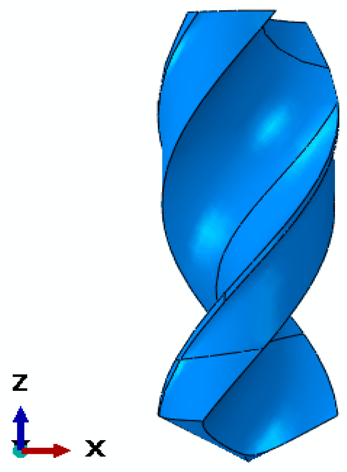
2.1.2. Geometric Modeling

The geometric model includes two parts: laminate workpiece model and cutting tool model. The geometric size of the laminate model is 100 × 100 × 6 mm. With the help of the composite material rapid modeling plug-in, the three-dimensional solid modeling was carried out. The number of layers was 10, and the layering method was [0°/90°]. After the workpiece model is established, the material properties shown in Table 1 below are assigned to the solid section. The temperature of the material in Table 1 refers to what temperature makes it easier to form during the forging process. The geometric model of the material and the stacking of layers are shown in Figure 1.
After the tool model is modeled in the three-dimensional modeling software, it can be directly imported into the finite element analysis software. The tool material of the drill is cemented carbide k44 material. The geometric parameters and material property information of the tool are shown in Table 2 and Table 3. The tool geometric model imported into the finite element software is shown in Figure 2.

2.2. Model Analysis Results

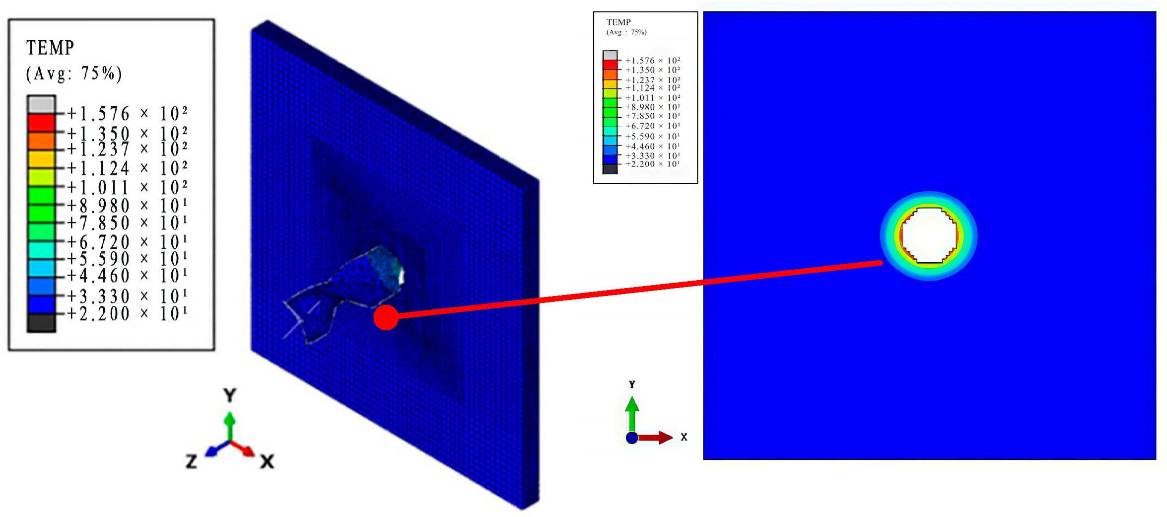
2.2.1. Analysis of Single Drilling Process Results

The visualization module of the finite element analysis software can visually display the cloud map of the tool and workpiece temperature field distribution while extracting the data results for the first hole analysis in the solver. Figure 3 shows the output result for the overall temperature field of the model. The temperature of the workpiece outlet layer at the end of the analysis is 157.6 °C. Figure 4 shows the variation law of the temperature distribution at the back of the tool surface with the axial feed. The temperature field of the tool begins to spread from the top angle. When the tool just touches the workpiece, the transverse edge plays the main cutting role, and the cutting heat is concentrated in the transverse edge part.
Through the output results, the relationship between the temperature of a single drilling process and the interlayer damage is analyzed. Figure 5 shows the variation curve of axial force RF3 with the feed depth of the tool during the single drilling process. It can be seen that with the removal of materials, the supporting force of the tool along the axial feed gradually decreases, and the axial force of the single drilling process also gradually decreases.
Figure 6 shows the variation law of the stratified damage variable during the axial feed process for single drilling. The layered damage spreads from the center of drilling to all sides, and the damage area gradually increases with the continuous progress of the drilling process.

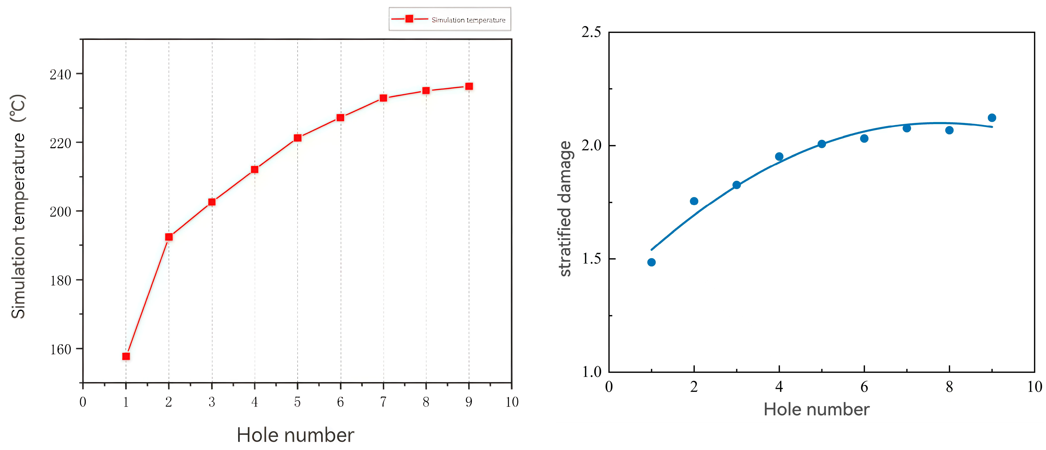
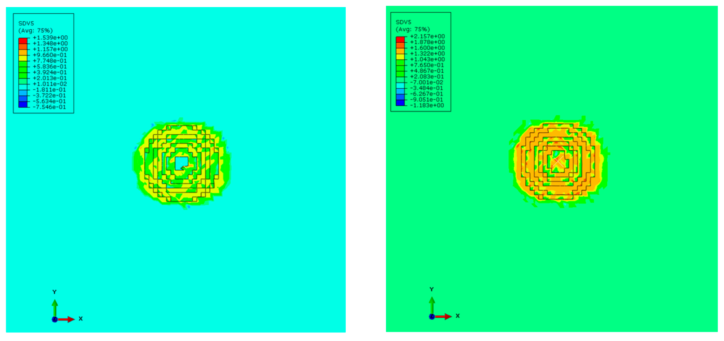
2.2.2. Analysis of Continuous Drilling Process Results

Figure 7 shows the output result for the temperature field in the ninth drilling process. After temperature accumulation in previous drilling processes, the peak temperature of the tool at the hole outlet is 202.6 °C. Figure 8 shows the changes in the maximum temperature of each hole and the stratified damage variable with the number of the drilling process in the continuous drilling model. When the temperature of hole 2 exceeds 180 °C, the mechanical properties of the material deteriorate significantly. Figure 9 shows a comparison of the stratified damage cloud map for hole 1 and hole 9, and it can be seen that the local stratified damage degree increases under the influence of temperature.
The delamination damage increases gradually with the accumulation of continuous perforating temperature. This is because the temperature has a greater influence on the matrix in the composite material, and the influence of temperature on the strength of the composite material is mainly reflected in the influence on the strength of the matrix. Although the axial force is closely related to the delamination damage, the material strength degrades and the interlayer strength decreases under the action of the continuous drilling temperature accumulation, which aggravates the delamination damage.
Based on an analysis of the above results, the location of the thermal joint of the film thermocouple can be obtained. The selection of the film thermocouple location needs to be specific; generally, the location of the thermal contact is arranged as close as possible to the highest point of the drilling temperature. Through the simulation results described above, it can be found that when drilling CFRP, the tool temperature is frequently higher than the workpiece temperature, and the higher cutting temperature points are mainly concentrated in the area near the back tool face and the back tool face near the main cutting edge. In this paper, the thermal electrode film of the thin-film thermocouple is arranged in the area of the back cutter surface.

3. Temperature Measuring Tools and Experimental Details

3.1. Experimental Equipment

By comparing the thin-film thermocouple with an ordinary thermocouple, it is found that the thin-film material has thinner thermal contact thickness and smaller thermal capacity than the bulk material of the ordinary thermocouple. Therefore, compared with the traditional thermocouple, the thin-film thermocouple has a faster response speed, and has certain advantages in capturing the transient temperature signal in the process of high-speed cutting [33]. At the same time, the functional layer film of the thin-film thermocouple can be made into different shapes using customized photolithography or magnetron sputtering masks, and the structure is extremely desirable. According to the test needs, the functional layer film is embedded in the key measurement area or position, and the temperature of the cutting area is reliably measured in situ as far as possible, so that the measurement purpose is more targeted.
In order to protect the film from the shear force parallel to the film plane, the film plane and the tool friction between the end face should be as vertical as possible or at a certain angle. It is necessary to embed the film in the tool material to achieve the protection of the film. Based on the above considerations, this paper proposes a split-type transformation scheme with a twist drill. In order to achieve convenience, a hexagonal crown bit with a diameter of 13 mm and a top angle of 140° is selected in this paper. The geometric features of the bit are shown in Figure 10.
The fitting formula between the output thermoelectric potential E of the sensor and the static calibration temperature is E = 0.0409 T - 1.017 , and Seebeck coefficient S is 40.9 μV/°C. As can be seen in Figure 11, the entire calibration temperature range is 30°C to 360°C, the correlation coefficient of the developed film thermocouple trend line is 0.9998, which is close to 1, and the fitting effect is good.
The linearity of the prepared film thermocouple is calculated. The calculated linearity of the film thermocouple is 0.354%, and the linearity is good. The dynamic response time of the sensor is 0.121 μs, which can reach the level of microseconds and meet the requirement for rapid capture of transient temperature signals during machining. Each part of the measuring tool is assembled to obtain a CFRP temperature-measuring tool for drilling based on the film thermocouple. Images of the physical tool are shown in Figure 12.

3.2. Experimental Details

In this experiment, the tool handle of the temperature-measuring tool and the cage installed are connected with the main shaft of the machine tool by pulling nails. The Zigbee receiver connects to the host computer through serial communication. Zigbee receiver is manufactured by Xinzhe CNC from Nanjing, China. All the above parts together constitute the CFRP drilling temperature test system, and the physical diagram of the test system is shown in Figure 13. The machine tool used in this experiment is an NMC-50VL vertical numerical control machining center of Xinzhe numerical control, which comes from Nanjing, China.
In this experiment, the shift in drilling quality is analyzed and discussed under different temperature ranges of the workpiece outlet layer during multi-hole continuous drilling. The continuous drilling test includes three different test conditions: an ordinary dry cutting continuous drilling test, minor flow cooling test, and large flow cooling test. The test specimen for the continuous drilling test was a 200 × 180 × 6 mm3 CFRP lamination, and the number of holes processed for continuous drilling was 45. In order to obtain a lower drilling temperature, the cutting heat in continuous drilling should be suppressed. The cooling test designed for comparison comprehensively considered the influence of cutting process parameters on the three. In this experiment, the spindle speed was 2000 rpm, and the feed speed was 30 mm/min for continuous machining, and the shift law of drilling damage was discussed in a wide temperature range. In order to obtain a lower drilling temperature, the cutting heat in continuous drilling needs to be suppressed, and the cooling test is designed for comparison.

4. Results and Discussion

The changes in maximum temperature and damage factor Fa with the number of holes under ordinary dry cutting conditions are shown in Figure 14. It can be seen that when the cutting heat is not inhibited, the temperature of the ordinary dry cutting outlet layer gradually accumulates with the increase in the number of holes drilled, but the degree of temperature accumulation between adjacent holes gradually decreases.
The value of delamination factor Fa can be obtained by the following equation [34]:
F a = D max D
where D max is the maximum diameter of the damage hole, and D is the hole diameter.
Figure 15 shows the overall outlet layer topography under ordinary dry cutting conditions. It can be seen that with the increase in continuous drilling temperature, the damage area around the outlet layer hole becomes larger, and the resin around the hole and the matrix are debonded, resulting in delamination. The maximum temperature range of the first eight holes is 100 °C~168 °C, and the damage factor is less than 0.3, which meets the requirement for the damage factor, so the maximum hole temperature should be limited to the range of 100 °C~168 °C.
Figure 16 shows the changes in maximum drilling temperature and hole surface roughness with the number of drilled holes under ordinary dry cutting conditions. It can be seen that the Ra value increases as a whole during continuous machining, but the range of Ra value change is different in different temperature ranges. When the temperature of the outlet layer is between 100 °C and 203 °C, the overall increase is slight, but the shift is relatively stable. When the temperature exceeds 203 °C, the Ra value rises sharply. In actual production, the Ra of composite materials is less than 3.2 μm, and the measurement method for metal materials is also adopted in this experiment by using a probe [35]. In order to meet the surface roughness requirements for a single hole, one should ensure that the Ra value is within 3.2 μm, and the continuous hole temperature should be limited to the range of 100 °C–203 °C.
Figure 17 shows the pore morphology of the outlet layer of 45 holes under low-flow cooling conditions. It can be seen that under this machining condition, there is virtually no large-scale damage to the outlet layer of each hole. Compared with ordinary dry cutting conditions, the damage of the outlet layer is significantly improved, there is no excessive uplift around the holes, and only a slight amount of tearing and delamination occur around the holes. Figure 18 shows the pore morphology of the outlet layer of 45 holes under the condition of low-flow cooling. It can be seen that there is almost no large-scale damage at the outlet layer of each hole under this processing condition. Compared with ordinary dry cutting conditions, the damage at the outlet layer is significantly improved, and there is no excessive uplift around the holes.
The variation trend in the surface roughness of the hole wall is shown in Figure 19, and the Ra value of each hole after machining is below the critical value. The Ra value gradually increased with the increase in the number of holes drilled, but the change in the value for the first 31 holes was relatively stable and remained below 1.5 μm. The overall growth rate of the Ra value accelerated after 31 holes, and the peak value of Ra in the whole process was obtained at the 43rd hole.
Figure 20 shows the relationship between the maximum drilling temperature and damage factor with the number of holes drilled, respectively, under the condition of large-flow cooling. It can be seen that under the influence of a large amount of liquid nitrogen and continuous spraying, the cutting heat was mostly suppressed, and the maximum temperature change during the drilling process was relatively stable. The maximum hole temperature should be controlled in the range of −1.25 °C~50.5 °C. Figure 21 shows a local diagram of the outlet side in the low temperature range.
Figure 22 shows the changes in outlet layer temperature and hole surface roughness with the number of holes drilled. It can be seen that the surface roughness Ra value for most holes could almost be maintained below the critical value within the entire temperature range.
Under normal dry cutting conditions, the temperature change range was 100 °C~212.75 °C, the temperature change range under small-flow liquid nitrogen cooling was 41.5 °C~121.5 °C, and the temperature change range under large-flow liquid nitrogen cooling was −25.75 °C~50.5 °C. The average values of the damage factor Fa and hole wall surface roughness Ra under the three different processing states were calculated and compared, as shown in Figure 23. Under the conditions of low-temperature-assisted processing with liquid nitrogen, the average Ra value was lower, and better surface quality of the inner holes could be obtained. Especially in the range of 41.5 °C~112 °C, the surface roughness Ra value for all holes was lower than 3 μm, and the average value was lower than that with large-flow liquid nitrogen cooling. In contrast, the best surface quality of the hole wall could be obtained under all three conditions.
Based on the above analysis results, across the entire temperature range of the three different drilling conditions, continuous drilling could ensure that the single-hole damage factor meets the standard temperature range of −1.25 °C–168.25 °C, and that the single-hole surface roughness meets the standard temperature range of −25.75 °C~201 °C.

5. Conclusions

In this paper, the influence of continuous drilling temperature on the quality of CFRP drilling was studied. Based on a macroscopic 3D drilling simulation model and thin-film thermocouple technology, the temperature characteristics of CFRP continuous drilling were studied in depth. The following conclusions can be drawn:
(1) The three-dimensional thermodynamic coupling model of CFRP can effectively predict the temperature distribution of the drilling tool, and the highest temperature appears on the back of the tool during continuous drilling.
(2) The results of continuous drilling experiments show that serious exit damage occurs when the maximum drilling temperature ranges from −25.75 °C to −9.75 °C and from 182 °C to 200.75 °C, and the surface roughness of the hole wall is consistent with the change law of temperature in the whole range.
(3) When the continuous hole temperature exceeds 207 °C, the roughness value changes greatly, which is not conducive to ensuring machining quality. Based on the test conditions and the quality standard, the optimum temperature range for CFRP continuous drilling is −1.25 °C~168.25 °C.

Author Contributions

F.C. developed the simulation model and wrote the paper, performed the experimental data analysis, and plotted the graphs; C.Z. checked the manuscript for review and supervision; H.W. supervised and checked the manuscript; Q.Z. performed the experiments and analyzed the data; and Q.X., D.S. and J.L. performed the data collection. All authors have read and agreed to the published version of the manuscript.

Funding

This research was funded by National Natural Science Foundation Youth Science Fund project, (No. 52305449), Scientific research project of Education Department of Liaoning Province, (No. LJKQZ20222336) and Natural Science Foundation of Liaoning Province, (No. 2024-MS-169).

Data Availability Statement

Data are contained within the article.

Conflicts of Interest

Chong Zhang is employed by the R&D Center, CRRC Tangshan Co., Ltd. The remaining authors state that the study was conducted without any business or financial relationship. The remaining authors have no conflict of interest.

References

  1. Zhu, W.; Fu, H.; Li, F.; Ji, X.; Li, Y.; Bai, F. Optimization of CFRP drilling process: A review. Int. J. Adv. Manuf. Technol. 2022, 123, 1403–1432. [Google Scholar] [CrossRef]
  2. Xu, J.; Yin, Y.; Davim, J.P.; Li, L.; Ji, M.; Geier, N.; Chen, M. A critical review addressing drilling-induced damage of CFRP composites. Compos. Struct. 2022, 294, 115594. [Google Scholar] [CrossRef]
  3. Mathiyazhagan, V.; Meena, A. Machining-induced damages in the drilling of CFRP under dry and cryogenic environments. Int. J. Adv. Manuf. Technol. 2024, 134, 605–626. [Google Scholar] [CrossRef]
  4. Ramirez, C.; Poulachon, G.; Rossi, F.; M’Saoubi, R. Tool wear monitoring and hole surface quality during CFRP drilling. In Proceedings of the CIRP Conference on Surface Integrity, Nottingham, UK, 28–30 May 2014. [Google Scholar]
  5. Bluemel, S.; Staehr, R.; Jaeschke, P.; Stute, U. Determination of Corresponding Temperature Distribution within CFRP during Laser Cutting. Phys. Procedia 2013, 41, 408–414. [Google Scholar] [CrossRef]
  6. Tsao, C.C. Experimental study of drilling composite materials with step-core drill. Mater. Des. 2008, 29, 1740–1744. [Google Scholar] [CrossRef]
  7. Feito, N.; Munoz-Sanchez, A.; Diaz-Alvarez, A.; Miguelez, M. Multi-objective optimization analysis of cutting parameters when drilling composite materials with special geometry drills. Compos. Struct. 2019, 225, 111187. [Google Scholar] [CrossRef]
  8. Nie, P.; Ma, Y.; Liu, S. Research on CFRP inner wall roughness during vibration drilling of CFRP/Ti based on acoustic emission. J. Phys. Conf. Ser. 2021, 1952, 032060. [Google Scholar] [CrossRef]
  9. Pérez, J.L.M.; Hodzic, A.; Merson, E.; Ayvar-Soberanis, S. Induced thermo-mechanical damage in the drilling of thermoplastic-toughened CFRP composites. In Proceedings of the 20th International Conference on Composite Materials ICCM-20, Copenhagen, Denmark, 19–24 July 2015. [Google Scholar]
  10. Pérez, J.L.M.; Hodzic, A.; Ayvar, S.; Merson, E. The influence of heat during short ageing periods on the mechanical properties of CFRP composites. In Proceedings of the 16th European Conference on Composite Materials ECCM-16, Seville, Spain, 22–26 June 2014. [Google Scholar]
  11. Pérez, J.L.M.; Hodzic, A.; Ayvar-Soberanis, S.; Merson, E.; Ayvar-Soberanis, S. On the temperatures developed in CFRP drilling using uncoated WC-Co tools Part II: Nanomechanical study of thermally aged CFRP composites. Compos. Struct. 2015, 123, 30–34. [Google Scholar] [CrossRef]
  12. Chatterjee, A. Thermal degradation analysis of thermoset resins. J. Appl. Polym. Sci. 2009, 114, 1417–1425. [Google Scholar] [CrossRef]
  13. Liu, J.; Chen, G.; Ji, C.; Qin, X.; Li, H.; Ren, C. An investigation of workpiece temperature variation of helical milling for carbon fiber reinforced plastics (CFRP). Int. J. Mach. Tool Manufact. 2014, 86, 89–103. [Google Scholar] [CrossRef]
  14. Zhu, G.P.; Bao, Y.J.; Ga, H. Research on the drilling temperature field model of the unidirectional carbon fiber epoxy composites. Adv. Mater. Res. 2012, 565, 478–483. [Google Scholar] [CrossRef]
  15. Sadek, A.; Shi, B.; Meshreki, M.; Duquesne, J.; Attia, M.H. Prediction and control of drilling-induced damage in fibre-reinforced polymers using a new hybrid force and temperature modelling approach. CIRP Ann.-Manuf. Technol. 2015, 64, 89–92. [Google Scholar] [CrossRef]
  16. Chen, C.; Wang, A.; Zheng, Z.; Zhao, Q.; Shi, Z.; Bao, Y. A Study on Drilling of CFRP/Ti Stacks: Temperature Field and Thermal Damage of the Interface Region. Materials 2023, 16, 2586. [Google Scholar] [CrossRef] [PubMed]
  17. Luo, B.; Hou, G.; Zhang, K.; Cheng, H. Hole-wall temperature characteristics in thick UD-CFRP drilling by different condition. Mater. Manuf. Process. 2024, 39, 563–576. [Google Scholar] [CrossRef]
  18. Li, S.; Teng, H.; Dai, L.; Zhou, Y.; Li, C.; Li, P.; Ko, T. Comprehensive prediction model of drilling temperature of UD-CFRP laminates considering the combined action of main cutting edge and chisel edge. Compos. Struct. 2023, 313, 116899. [Google Scholar] [CrossRef]
  19. Wang, F.J.; Yin, J.W.; Ma, J.W.; Niu, B. Heat Partition in Dry Orthogonal Cutting of Unidirectional CFRP Composite Laminates. Compos. Struct. 2018, 197, 28–38. [Google Scholar] [CrossRef]
  20. Komanduri, R.; Hou, Z.B. A Review of the Experimental Techniques for the Measurement of Heat and Temperatures Generated in Some Manufacturing Processes and Tribology. Tribol. Int. 2001, 34, 653–682. [Google Scholar] [CrossRef]
  21. Brinksmeier, E.; Fangmann, S.; Rentsch, R. Drilling of Composites and Resulting Surface Integrity. CIRP Ann-Manuf. Technol. 2011, 60, 57–60. [Google Scholar] [CrossRef]
  22. Fu, R.; Jia, Z.; Wang, F.; Jin, Y.; Sun, D.; Yang, L.; Cheng, D. Drill-exit temperature characteristics in drilling of UD and MD CFRP composites based on infrared thermography. Int. J. Mach. Tools Manuf. Des. Res. Appl. 2018, 135, 24–37. [Google Scholar] [CrossRef]
  23. Hou, G.Y.; Luo, B.; Zhang, K.F.; Luo, Y.X.; Liu, P.; Cao, S.P.; Li, Y. Effects of Heat Accumulation on the Characteristics of Hole Wall Temperature and Damages in Drilling of UD CFRP. Int. J. Adv. Manuf. Technol. 2021, 115, 1529–1546. [Google Scholar] [CrossRef]
  24. Butler-Smith, P.W.; Axinte, D.A.; Daine, M.; Kennedy, A.R.; Harper, L.T.; Bucourt, J.F.; Ragueneau, R. A study of an improved cutting mechanism of composite materialsusing novel design of diamond micro-core drills. Int. J. Mach. Tool Manufact. 2015, 88, 175–183. [Google Scholar] [CrossRef]
  25. Choudhury, M.R.; Srinivas, M.S.; Debnath, K. Experimental investigations on drilling of lignocellulosic fiber reinforced composite laminates. J. Manuf. Process. 2018, 34, 51–61. [Google Scholar] [CrossRef]
  26. Wang, C.Y.; Ming, W.W.; An, Q.L.; Chen, M. Machinability Characteristics Evolution of CFRP in a Continuum of Fiber Orientation Angles. Mater. Manuf. Process. 2017, 32, 1041–1050. [Google Scholar] [CrossRef]
  27. Hintze, W.; Schutte, C.; Steinbach, S. Influence of the Fiber Cutting Angle on Work Piece Temperature in Drilling of Unidirectional CFRP. In New Production Technologies in Aerospace Industry: Proceedings of the 4th Machining Innovations Conference, Hannover, Germany, 18–19 September 2013; Springer: Cham, Switzerland, 2013; pp. 137–143. [Google Scholar]
  28. Xu, J.Y.; Zhou, J.; Chen, M.; Ren, F. Experimental Study on Mechanical Drilling of Carbon/Epoxy Composite-Ti6Al4V Stacks. Mater. Manuf. Process. 2019, 34, 715–725. [Google Scholar] [CrossRef]
  29. Wang, C.Y.; Chen, Y.H.; An, Q.L.; Cai, X.J.; Ming, W.W.; Chen, M. Drilling temperature and hole quality in drilling of CFRP/aluminum stacks using diamond coated drill. Int. J. Precis. Eng. Manuf. 2015, 16, 1689–1697. [Google Scholar] [CrossRef]
  30. Sato, M.; Aoki, T.; Tanaka, H.; Takeda, S. Measurement of temperature at bottom surface of hole in drilling of CFRP and titanium stack. In Proceedings of the International Conference on Leading Edge Manufacturing in 21st Century, Matsushima, Japan, 7–8 November 2013; Volume 7, pp. 448–451. [Google Scholar]
  31. Guo, Q.; Yao, W.; Li, W.; Gupta, N. Constitutive models for the structural analysis of composite materials for the finite element analysis: A review of recent practices. Compos. Struct. 2021, 260, 113267. [Google Scholar] [CrossRef]
  32. Trzepieciński, T.; Najm, S.M.; Lemu, H.G. Current concepts for cutting metal-based and polymer-based composite materials. J. Compos. Sci. 2022, 6, 150. [Google Scholar] [CrossRef]
  33. Lian, Y.; Chen, X.; Zhang, T.; Liu, C.; Lin, L.; Lin, F.; Li, Y.; Chen, Y.; Zhang, M.; Zhou, W. Temperature measurement performance of thin-film thermocouple cutting tool in turning titanium alloy. Ceram. Int. 2023, 49, 2250–2261. [Google Scholar] [CrossRef]
  34. Davim, J.; Reis, P. Study of delamination in drilling carbon fiber reinforced plastics (CFRP) using design experiments. Compos. Struct. 2003, 59, 481–487. [Google Scholar] [CrossRef]
  35. Chen, Y.; Guo, X.; Zhang, K.; Guo, D.; Zhou, C.; Gai, L. Study on the surface quality of CFRP machined by micro-textured milling tools. J. Manuf. Process. 2019, 37, 37114–37123. [Google Scholar] [CrossRef]
Figure 1. Geometric model and stacking diagram of CFRP laminate.
Machines 12 00809 g001
Figure 2. Tool geometry model.
Machines 12 00809 g002
Figure 3. Visualization results for temperature field of single drilling model.
Machines 12 00809 g003
Figure 4. Process of tool temperature field change after single drilling.
Machines 12 00809 g004
Figure 5. Thrust force output results during single drilling process.
Machines 12 00809 g005
Figure 6. Progressive delamination damage process during single drilling.
Machines 12 00809 g006
Figure 7. Temperature field output results for the ninth drilling process.
Machines 12 00809 g007
Figure 8. Simulation of the variation in maximum temperature and delamination damage with the number of the drilling process.
Machines 12 00809 g008
Figure 9. Comparison of stratified damage variable with delamination damage in holes 1 and 9.
Machines 12 00809 g009
Figure 10. The drilling material object and geometric modeling.
Machines 12 00809 g010
Figure 11. Static calibration data and fitting results.
Machines 12 00809 g011
Figure 12. Physical image of temperature-measuring tools.
Machines 12 00809 g012
Figure 13. CFRP drilling temperature testing system.
Machines 12 00809 g013
Figure 14. The change in outlet layer temperature and damage factor with the number of holes in ordinary dry cutting.
Machines 12 00809 g014
Figure 15. Morphology of the outlet layer of each hole in ordinary dry cutting.
Machines 12 00809 g015
Figure 16. The variation in outlet layer temperature and hole wall surface roughness with the number of holes in ordinary dry cutting.
Machines 12 00809 g016
Figure 17. Changes in outlet layer temperature and damage factor with the number of holes drilled under low-flow cooling conditions.
Machines 12 00809 g017
Figure 18. Morphology of outlet layers of each hole during low-flow cooling processing.
Machines 12 00809 g018
Figure 19. The variation in outlet layer temperature and hole wall surface roughness with the number of holes drilled.
Machines 12 00809 g019
Figure 20. Change in the damage factor and surface roughness of hole wall with the number of holes drilled.
Machines 12 00809 g020
Figure 21. Change in the damage factor and surface roughness of hole wall with the number of holes drilled.
Machines 12 00809 g021
Figure 22. Variation in outlet layer temperature and hole wall surface roughness with the number of holes drilled.
Machines 12 00809 g022
Figure 23. Comparison of damage factors and average surface roughness values obtained with continuous drilling under three different conditions.
Machines 12 00809 g023
Table 1. Multi-direction CFRP laminate material properties.
Material PropertyMaterial TemperatureNumerical Value
Density (g/cm3) 1.58
Fiber volume fraction 62 ± 0.3%
Elastic property
Modulus of elasticity
(GPa)
22 °CE11 = 114; E22 = E33 = 7.27; G12 = G13 = 4.54; G23 = 2.59; ν12 = ν12 = 0.29; ν23 = 0.4
180 °CE11 = 107; E22 = E33 = 4.42; G12 = G13 = 4.22; G23 = 1.65; ν12 = ν12 = 0.29; ν23 = 0.4
Tensile strength
(Mpa)
22 °CXT = 1677; XC = 1249; YT = ZT = 20; YC = ZC = 140; S12 = S13 = S23 = 129
180 °CXT = 1240; XC = 439; YT = ZT = 15; YC = ZC = 100; S12 = S13 = S23 = 35
Thermal property
Heat conductivity (W/m·K)22 °Ck11 = 2.95; k22 = k33 = 0.64
180 °Ck11 = 4.13; k22 = k33 = 0.81
Specific heat capacity (J/Kg·K)22 °CCp = 750
180 °CCp = 1206
Damage parameter
Breaking energy (N/mm)22 °CGft = 133; Gfc = 40; Gmt = Gzmt = 0.6; Gmc = Gzmc = 2.1
Table 2. The tool geometry.
Geometric ParameterNumerical Value
Diameter (mm)13
Parietal angle (°)120
Posterior angle (°)0.22
Cutting edge width (mm)1.3
Spiral angle (°)30
Table 3. The tool material properties.
Material PropertyNumerical Value
Density (g/cm3)1.58
Modulus of elasticity (GPa)580
Poisson’s ratio0.22
Thermal conductivity (W/m·K)62.8
Specific heat capacity (J/Kg·K)460
Disclaimer/Publisher’s Note: The statements, opinions and data contained in all publications are solely those of the individual author(s) and contributor(s) and not of MDPI and/or the editor(s). MDPI and/or the editor(s) disclaim responsibility for any injury to people or property resulting from any ideas, methods, instructions or products referred to in the content.

