5.1. Stage I—Requirement Identification and Context Analysis
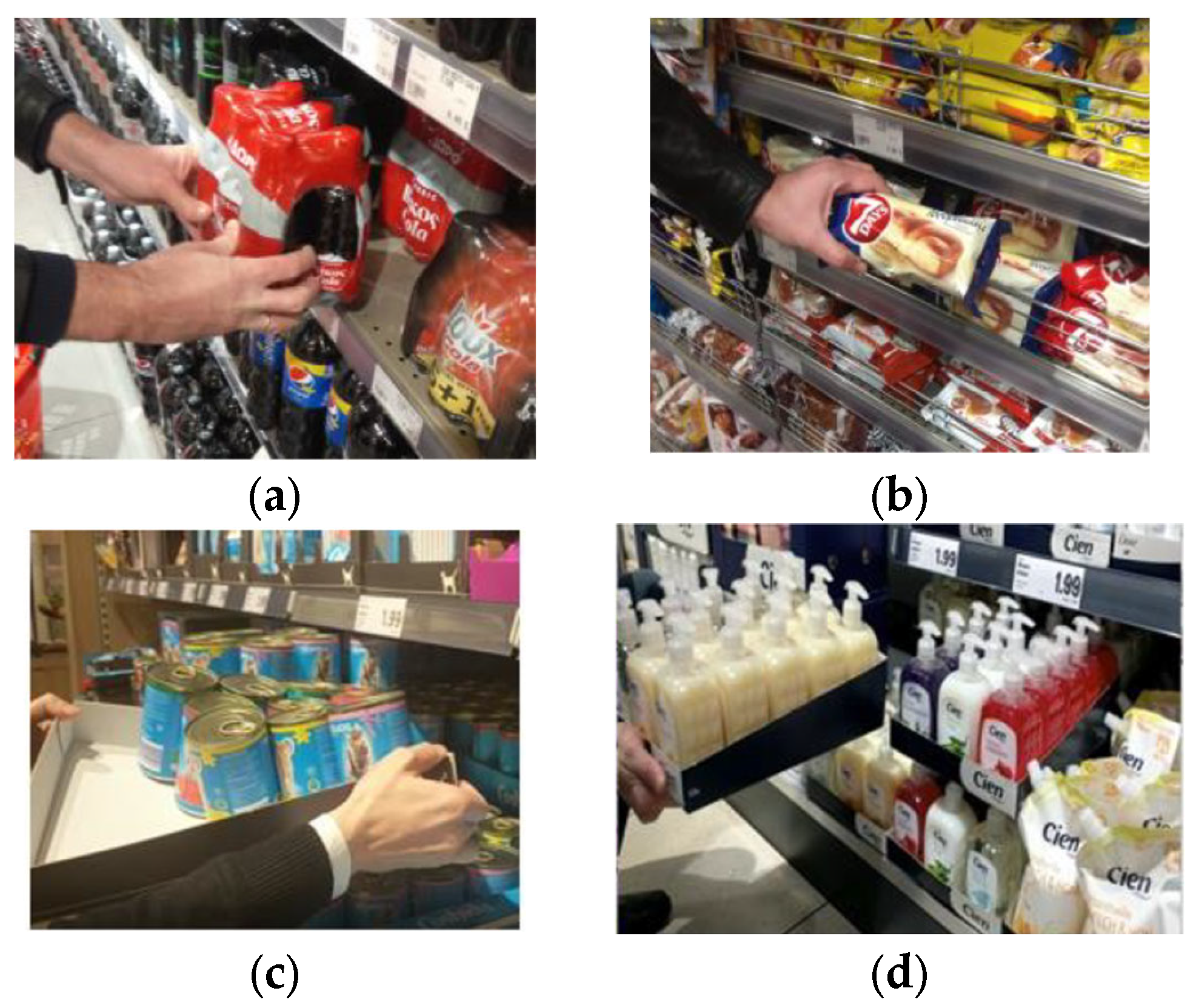
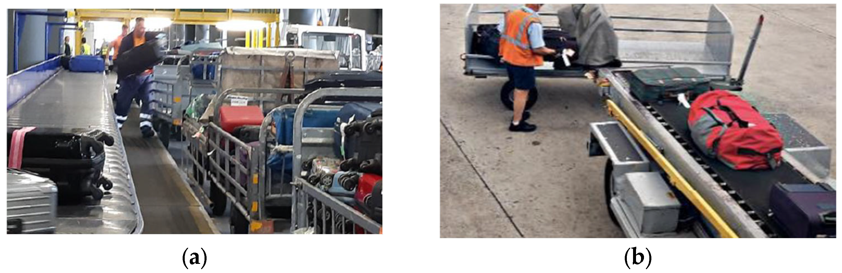
The MANiBOT platform was conceived to operate in two demanding, real-world domains: supermarket shelf restocking and airport baggage handling. From these scenarios, a set of functional and operational requirements was derived, forming the foundation of the design process.
In accordance with systems-engineering principles, the requirements were classified into Functional Requirements (FR) and Operational Requirements (OR).
Functional requirements describe what the system must do—that is, the intrinsic capabilities, behaviors, and design features needed to fulfill its intended tasks.
Operational requirements, in contrast, define under what conditions and constraints the system must operate, including environmental, regulatory, and maintainability aspects.
This distinction provides a clear structure for translating high-level mission objectives into verifiable engineering specifications, ensuring that both the internal functionality of the platform and its interaction with real-world environments are consistently addressed.
The MANiBOT robotic platform’s Functional Requirements are as follows:
FR1—Dual-arm capability: The platform shall host two collaborative manipulators enabling coordinated bimanual operation.
FR2—Workspace overlap: The manipulators shall provide sufficient workspace overlap to enable cooperative tasks and safe handover operations.
FR3—Conveyor subsystem integration: The structure shall include a conveyor system allowing coordinated object transfer between manipulators or external stations.
FR4—Structural rigidity under payload: The mechanical frame shall maintain elastic behavior under payloads up to 11 kg per arm at maximum reach.
FR5—Stability on AMR base: The system shall preserve static and dynamic stability when mounted on autonomous mobile robots (AMRs), including tilting conveyor configurations.
FR6—Modularity and maintainability: The platform shall support modular assembly and easy access for servicing, ventilation, and subsystem replacement.
FR7—Allocation of internal components: Adequate internal space shall be reserved for computing units, controllers, and sensors, ensuring organized cable routing and protection.
FR8—Symmetry and balance: The overall design shall maintain a geometrically symmetrical configuration to simplify control, equalize loads, and minimize torsional stresses.
On the other hand, the following Operational Requirements for the MANiBOT robotic platform have been identified:
OR1—Spatial validation and AMR adaptability: The footprint and mounting interface shall be compatible with multiple AMR bases (e.g., P204, P604) while preserving geometric stability.
OR2—Working height and task range: The manipulators and conveyor shall jointly enable operation between 0.5 m and 2.5 m, covering all expected manipulation heights.
OR3—Safety and regulatory compliance: The design shall conform to collaborative-robot standards, including [
11,
12], ensuring safe human–robot coexistence.
OR4—Maintainability and service access: The platform shall feature accessible panels, guided cable routing, and proper ventilation to facilitate maintenance and minimize MTTR.
OR5—Integration of power and computing systems: The platform shall provide sufficient energy capacity and internal integration for computing resources (NUCs, Jetsons, industrial PC), ensuring electromagnetic compatibility (EMC) and operational autonomy.
Together, these requirements define the baseline constraints and performance objectives guiding the conceptual, detailed, and validation stages of the MANiBOT platform, as summarized in
Table 1 and later traced across successive design iterations.
5.2. Stage II—Conceptual Design of the Platform: Space Exploration and Initial Configuration
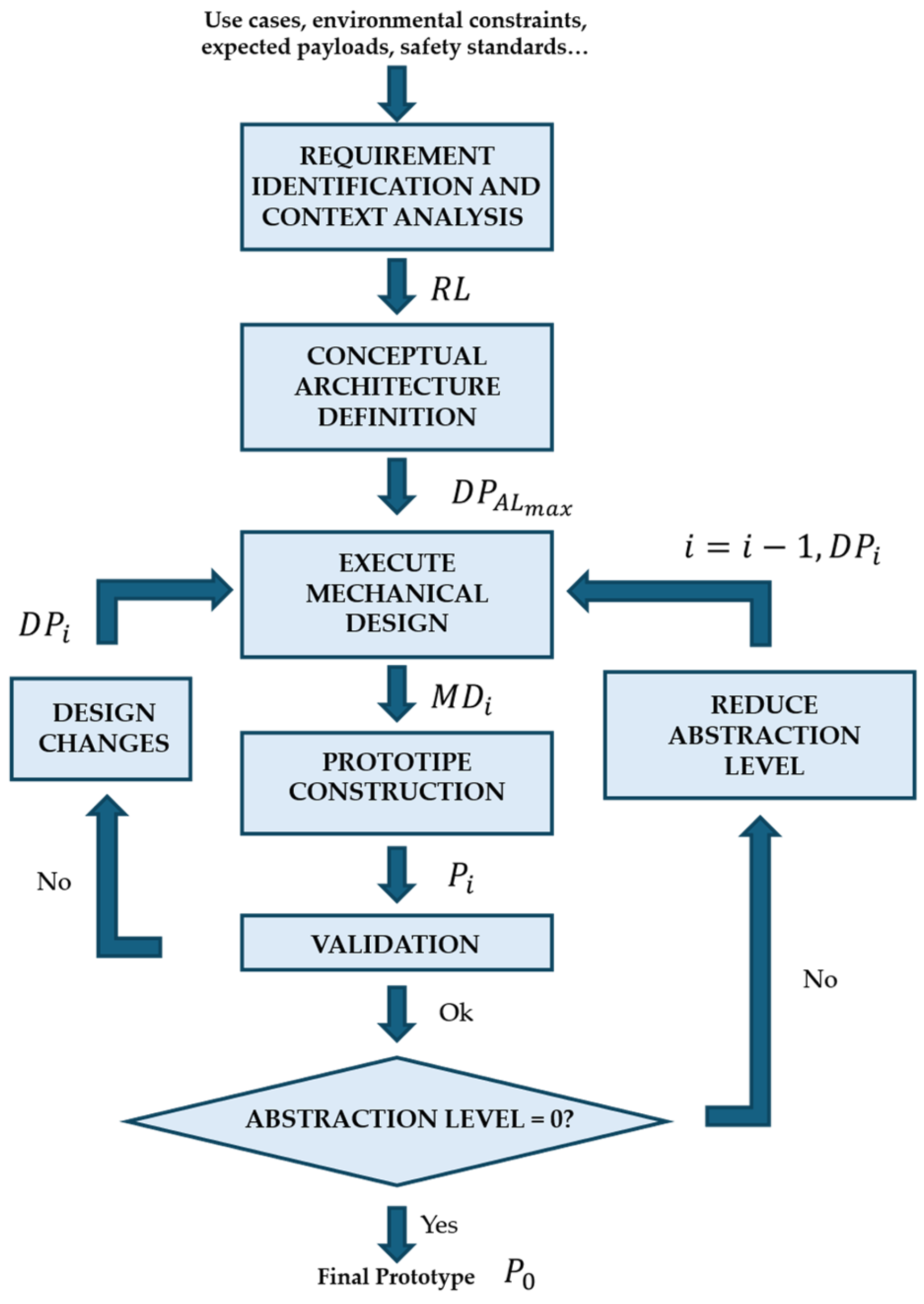
The mechanical development of the MANiBOT platform followed a stepwise, iterative refinement cycle explicitly aimed at aligning the structure with the demanding requirements of retail and airport scenarios. Over twelve main iterations, the system gradually evolved from a purely volumetric concept into a mature, modular, and robust solution ready for experimental validation.
In accordance with the conceptual architecture definition stage, this phase focused on transforming the initial system requirements and environmental constraints into a tangible structural concept. The process explicitly addressed the selection and positioning of manipulators, the geometric definition of the support frame, the preliminary choice of materials and joining strategies, and the exploration of modular configurations to ensure long-term adaptability. Conceptual tools such as digital mock-ups, reachability analyses, and ergonomic evaluations were applied to validate feasibility prior to detailed design.
Version 1—Conceptual volumetric mock-up.
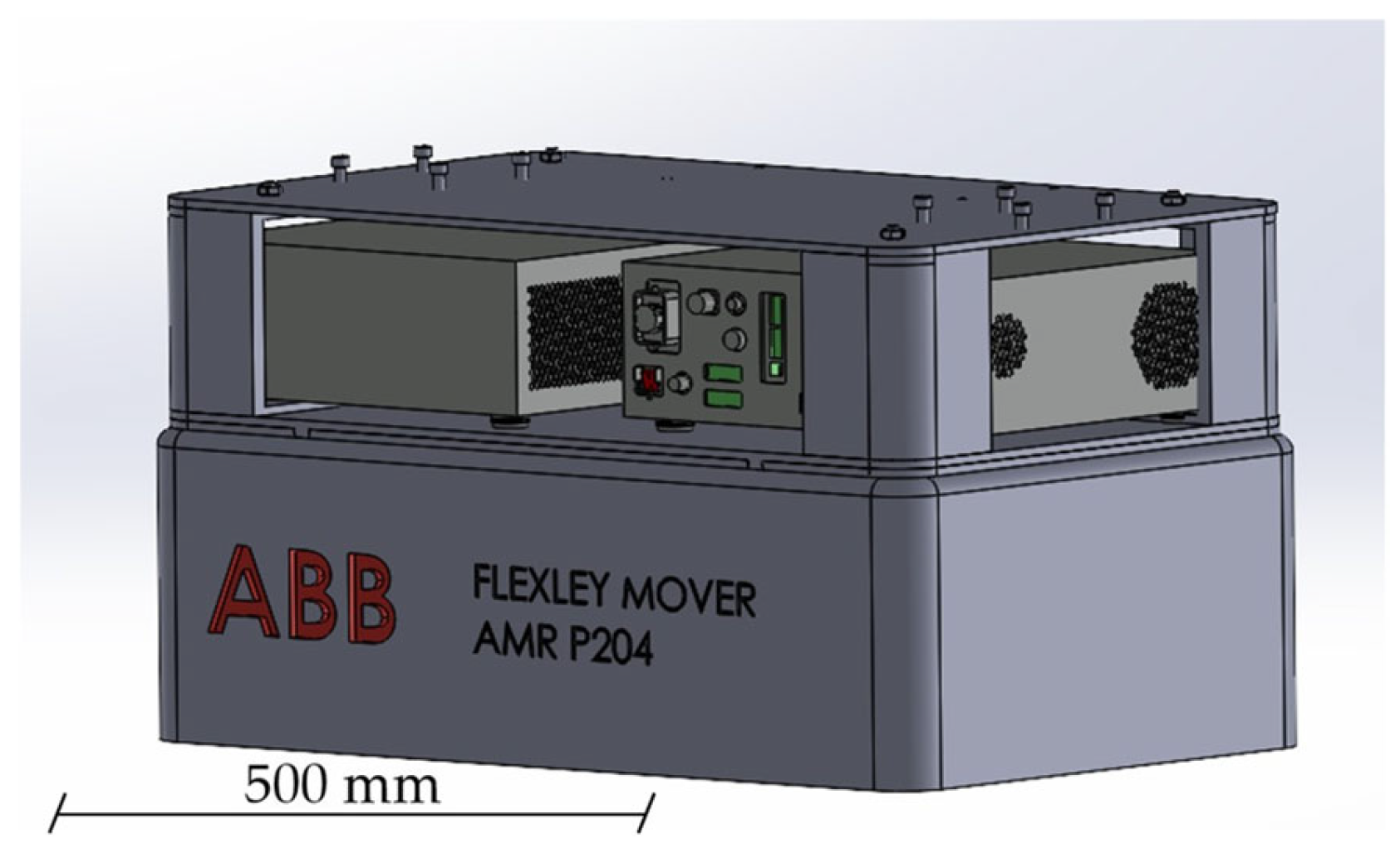
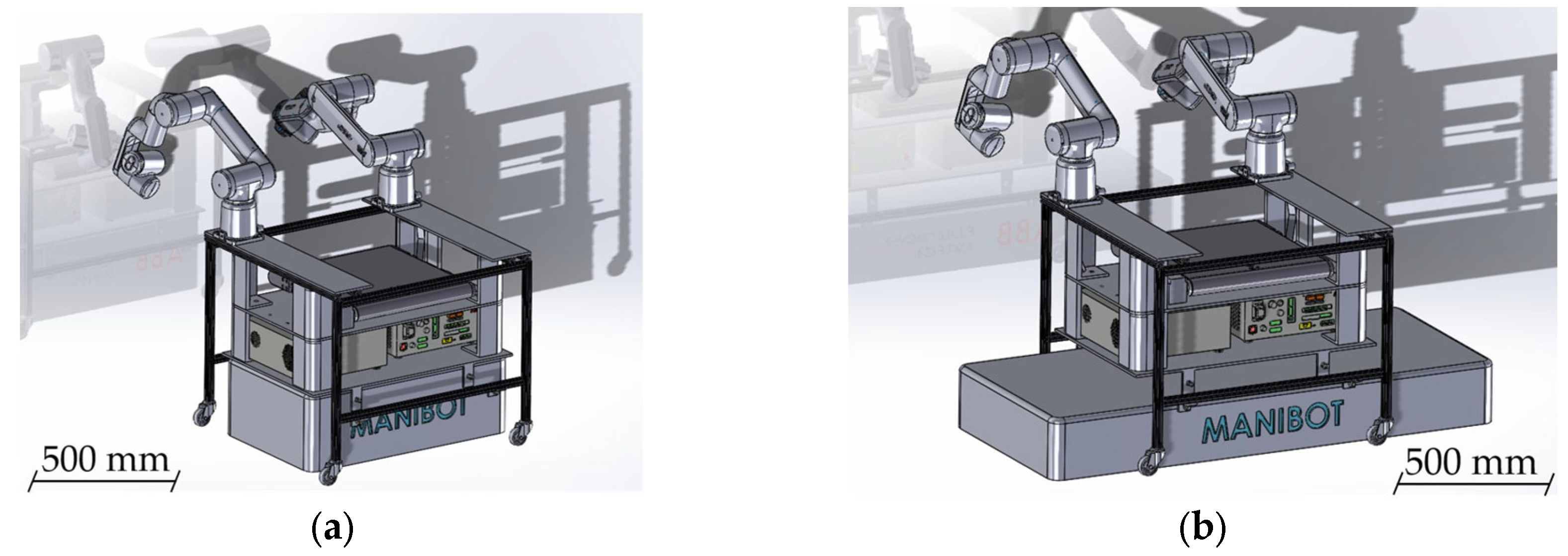
The very first iteration (
Figure 4) was conceived as a volumetric envelope corresponding to the P204 AMR footprint. At this stage, the focus was on defining the global geometry of the platform, evaluating height, footprint, and workspace accessibility (Objective II), taking into account that the manipulators will be on top (Objective I), or at least a common solution for the possible ones. Its purpose was not yet to host detailed components, but rather to provide an initial spatial framework for discussing the integration of manipulators, conveyor belts, and auxiliary modules. Reachability maps were generated to verify the potential workspace overlap between future manipulators. At this stage, the search for robotic manipulators was narrowed down to three possible candidates: CRB15000/95, CRB15000/127, and CRB15000/152.
This conceptual model enabled an early evaluation of the physical footprint, highlighted potential constraints for actuator placement, and served as a collaborative reference for aligning design perspectives across project partners.
Version 2—Adaptation to multiple AMR bases.
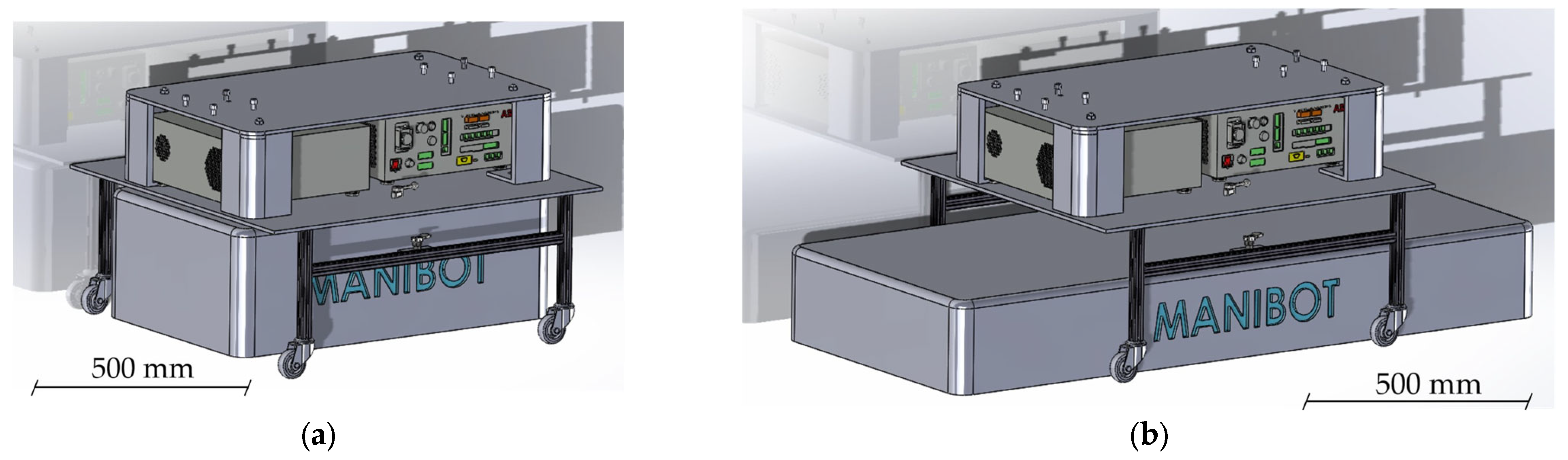
Building upon the volumetric concept, the second design iteration (
Figure 5) addressed the need to ensure compatibility with different AMR geometries. The frame geometry was redefined to balance accessibility and stiffness, while an intermediate structure was introduced to guarantee ergonomic working heights (Objective II). A new intermediate frame was introduced as a structural interface, effectively elevating the upper platform while creating an intermediate compartment for cabling and electronics. This modular connection allowed flexible coupling to several mobile bases without compromising rigidity. At this stage, preliminary considerations for ventilation, power interfaces, and service panels were introduced, marking a transition from purely conceptual modeling to functional design. This version directly addressed, for the first time, the requirements of selecting preliminary materials and joining strategies (Objective III) and exploring adaptable configurations for future evolution (Objective IV). Future iterations will be the result of improving these objectives.
Version 3—Extended structure and internal reorganization.
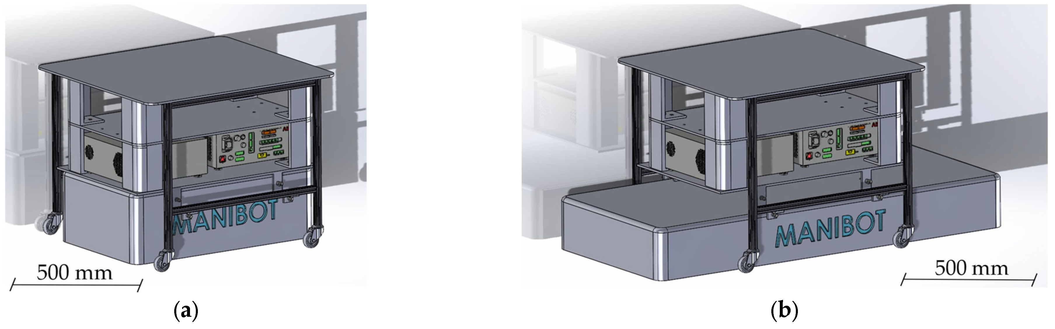
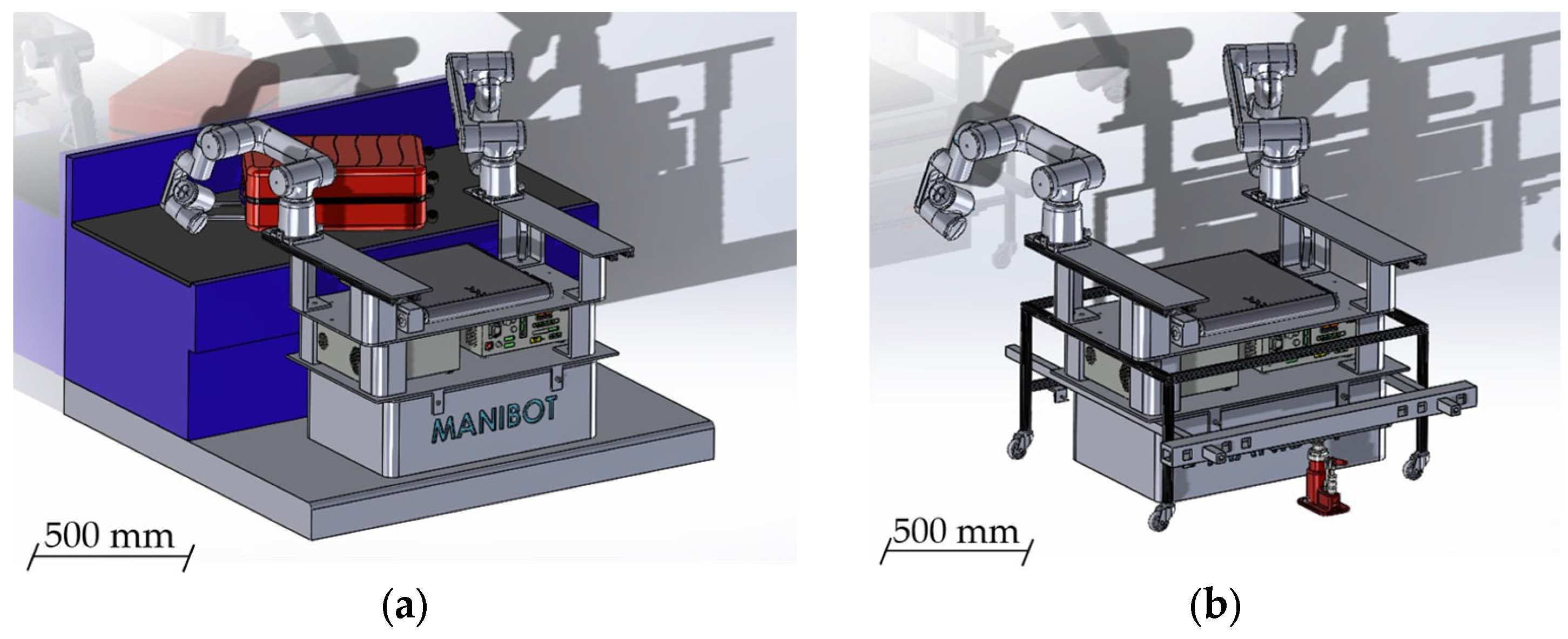
The third iteration (
Figure 6) incorporated additional components identified as essential for operability, which required a redefinition of the external dimensions and vertical organization of the platform. This design ensured that the relative positioning of the two temporarily chosen manipulators (CRB15000/95) would provide sufficient workspace overlap while minimizing interference, in direct fulfillment of Objective I. The structure was extended in height, introducing a new upper level envisioned as a potential working surface or mounting point for manipulators and sensors. Internally, compartments were reorganized to improve accessibility to control and communication modules, simplifying future maintenance, while maintaining the modularity (Objective IV).
Version 4—Integration of manipulators and central conveyor.
The fourth design iteration (
Figure 7) marked the first major step from conceptual modeling to functional prototyping. For the first time, active robotic components were introduced, with two ABB CRB15000/95 manipulators selected as a baseline following the earlier comparative analysis of potential arms (Objective I). Their installation allowed an initial evaluation of dual-arm feasibility, particularly regarding workspace overlap, potential interferences, and collaborative reach. In parallel, a central conveyor belt was incorporated as a placeholder subsystem, enabling early assessment of transfer operations between the manipulators or toward external stations. Although its dimensions were not yet finalized, the conveyor offered valuable insights into accessibility, interaction with moving objects, and workflow organization.
Structurally, this version consolidated anchoring reinforcements (Objective III) and introduced a detachable second level (Objective IV), partially elevating the upper platform to facilitate coupling with multiple AMRs. This modular capability transformed a key principle from earlier iterations into a tangible design feature, while also improving accessibility to control panels and ventilation systems.
Version 5—Virtual integration, structural reinforcement, and lifting system.
The fifth iteration (
Figure 8) represented a substantial leap in maturity, as the MANiBOT platform was integrated for the first time into a simulated airport baggage-handling environment. Within this virtual setup, manipulator reach, accessibility, and coordination were validated against a conveyor belt and representative test objects such as suitcases. This virtual integration validated both the global geometry of the support structure and the manipulators’ spatial coordination under realistic constraints (Objectives I and II).
From a mechanical perspective, the structure was redesigned using standardized extruded aluminum profiles, enhancing rigidity while maintaining modularity and compatibility with industrial fastening systems (Objective III). A critical innovation of this version was the introduction of the first lifting system, located at the lower part of the frame, which allowed safe detachment and transfer of the platform between different AMR bases. Together, these advances consolidated the platform as a modular, structurally robust prototype (Objective IV), bridging the gap between conceptual development and operational validation.
Version 6—Sheet-metal feasibility study.
The sixth design iteration (
Figure 9) explored an alternative manufacturing pathway based on folded sheet-metal panels. This approach addressed Objective III by testing a different material, and therefore a new joining strategy, that minimized welding while embedding reinforcement features directly into the bending process. Unlike previous profile-based designs, this approach aimed to simplify production, reduce costs, and embed reinforcement features directly into the bending process, thereby minimizing welding and mechanical joints.
Functionally, the layout preserved the core architecture defined in earlier versions: elevated manipulators, a centrally positioned conveyor, front access to electronics, and compatibility with the lifting system. Simulation in the airport scenarios was maintained, ensuring continuity in evaluating interaction with objects and carts. Although conceived as an exploratory branch rather than the definitive design, this version demonstrated the feasibility of transitioning toward pre-industrial manufacturing while preserving all essential functionalities. With this approach, the design lost some modularity (Objective IV was not as fully satisfied as in previous iterations), but it served to verify scalability and manufacturability.
Version 7—Linear system integration and transition to GoFa 12 manipulators.
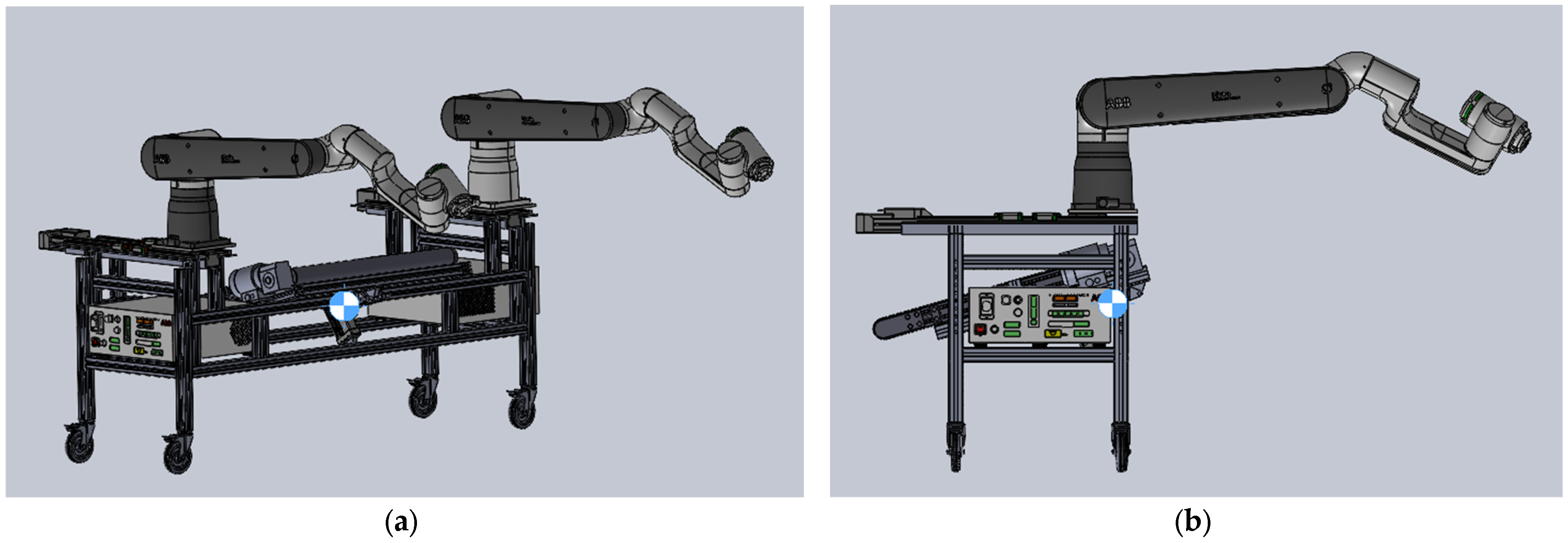
The seventh design iteration (
Figure 10) introduced two decisive advancements: the implementation of linear motion capabilities and the adoption of higher-performance manipulators. Manipulator positioning was revisited to confirm workspace overlap across extended trajectories (Objective I). Mechanically, this version refined the previously explored sheet-metal architecture while equipping one robotic arm with a linear track, substantially extending its operational envelope. This addition enabled the evaluation of tasks requiring longitudinal reach—such as handling distributed objects along a conveyor belt—and provided valuable insights into trajectory planning and kinematic constraints in extended workspaces. Material selection and stiffness calculations were reassessed, confirming the structural feasibility of supporting higher payloads (Objective III).
Simultaneously, the original GoFa 5 manipulator, which was not mounted on the linear track, was replaced with a GoFa 12. This upgrade, motivated by the need to address more demanding payload and reach requirements, allowed the team to perform more realistic simulations involving heavier objects and greater distances from the central platform. As a result, this iteration effectively converged structural robustness, functional flexibility, and workspace analysis, marking a turning point toward readiness for physical prototyping and validation.
Version 8—Consolidated design with folded sheet-metal structure, linear tracks, and GoFa 12 arms.
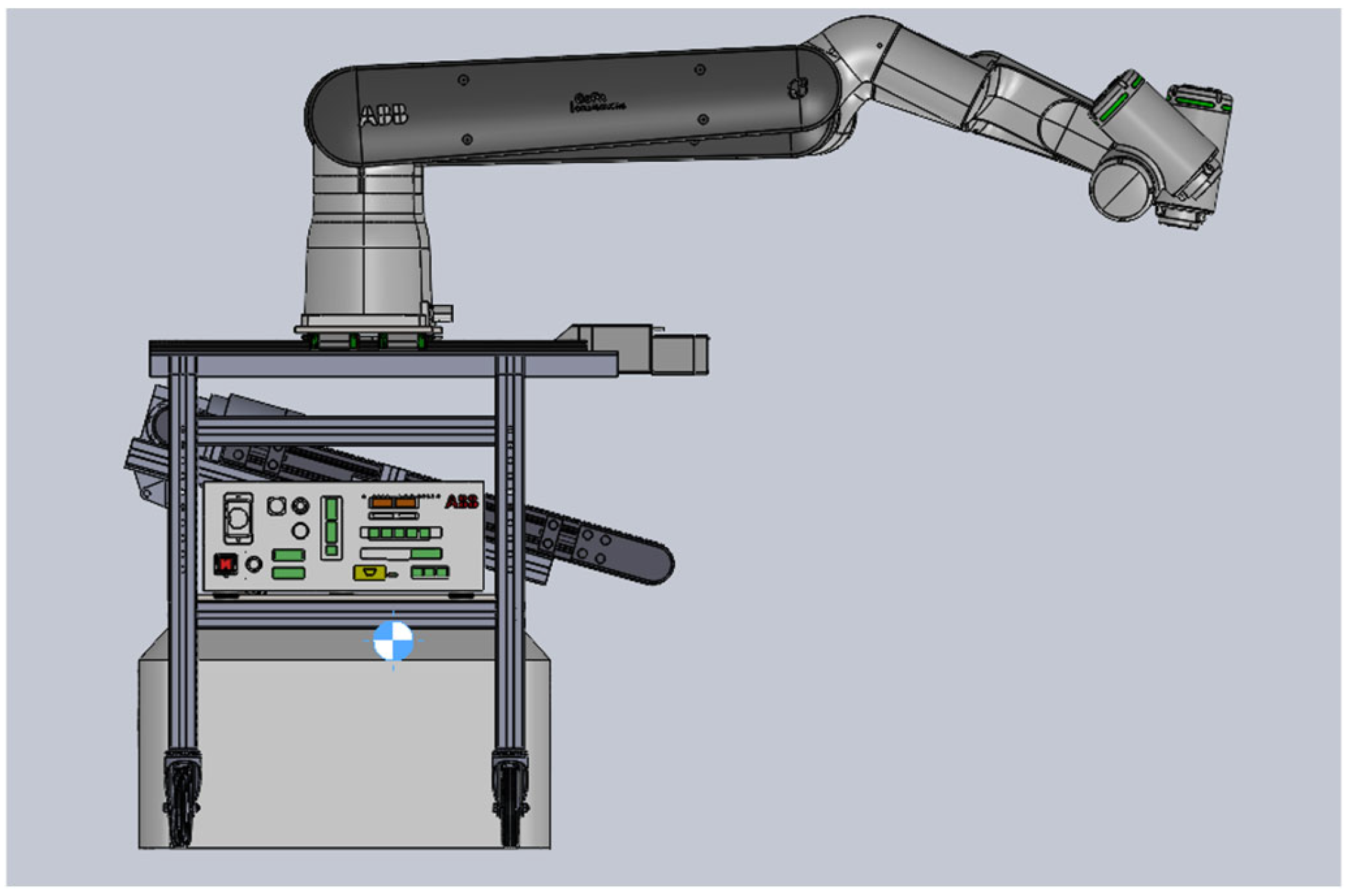
The eighth iteration (
Figure 11) represents the most advanced stage of the sheet-metal-based design pathway and served as the foundation for critical final decisions regarding both structure and manipulation hardware. At this stage, all four conceptual objectives were demonstrably satisfied: (I) optimal dual-arm positioning with minimal interference, (II) a well-defined support geometry balancing footprint, height, and accessibility, (III) material and joining strategies combining folded sheet-metal and bolted reinforcements, and (IV) a modular configuration adaptable to future AMRs and use cases.
Structurally, the geometry was carefully refined for efficient fabrication through bending processes, ensuring rigidity while maintaining lightweight properties. Mounting points, ventilation paths, and access to electronic compartments were systematically addressed, consolidating the design’s maintainability and manufacturability. Functionally, the introduction of two linear tracks allowed each manipulator to extend its workspace significantly, supporting complex collaborative tasks and enabling simultaneous access to multiple zones around the central conveyor. Moreover, the linear motion system was re-engineered into a set of three coordinated elements—one actuator flanked by two supporting linear guides—that together absorb the moments generated at the base of the manipulators. Compared to a single heavy-duty linear track, this configuration provides a much more reliable and cost-effective solution, while still offering the stiffness required to withstand the significant loads induced during extended-reach operations.
The decision to adopt two GoFa 12 arms as the definitive manipulators confirmed the trajectory initiated in the previous iteration, providing the payload, precision, and reach required for the project’s most demanding scenarios. Their integration with the linear tracks produced a highly versatile configuration, capable of addressing both retail and airport scenarios with increased adaptability and operational efficiency.
5.3. Stage III—Detailed Mechanical Design and Structural Analysis
In this stage, the previously defined conceptual architecture was refined into a fully parameterized and manufacturable mechanical system. Using CAD and simulation tools, the design team optimized mass distribution and center of gravity (Objective I), conducted finite element analyses to evaluate stiffness and stress (Objective II), performed dynamic and kinematic simulations to ensure collision-free operation (Objective III), detailed the conveyor and lifting subsystems (Objective IV), and defined interfaces for sensors, actuators, and computing units (Objective V). The outcome of this stage was an optimized CAD model, a complete structural analysis, and an integration plan ready for prototyping.
Version 9—Modular architecture with aluminum profiles and optimized linear motion system.
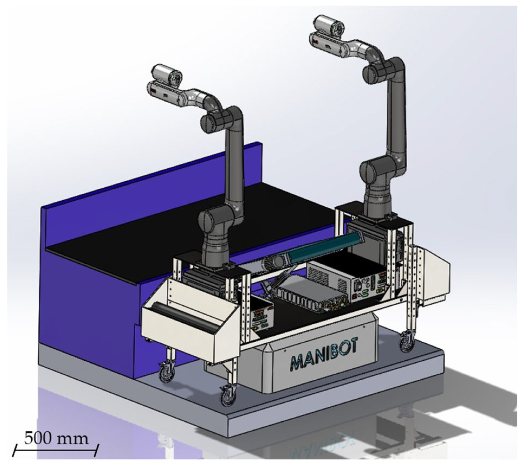
The ninth design iteration (
Figure 12) marked a strategic shift toward a fully modular configuration. Departing from the folded sheet-metal concept, this version adopted an extruded aluminum profile structure, enabling a platform that could be easily reconfigured to accommodate different use cases, environments, or future modifications without requiring extensive redesign. The use of standardized profiles provided multiple advantages: reduced weight, high mechanical strength, simplified assembly, and compatibility with widely available industrial fastening systems.
Within this framework, all critical subsystems were integrated for the first time in a coherent assembly: the two GoFa 12 manipulators, the central conveyor belt, and an improved linear track system. The latter was reinforced with dual linear guides, significantly enhancing stability under extended-reach maneuvers and dynamic loads. This redesign ensured accurate positioning of devices, maintaining the center of gravity at the midpoint of the platform by preserving symmetry (Objective I).
Equally important, this version introduced the first functional prototype of the conveyor subsystem, fully embedded into the aluminum frame (Objective III). While still subject to refinements in speed and geometry, it enabled preliminary experiments on coordinated manipulator–conveyor interaction, including luggage-handling scenarios representative of airport operations. In addition, the first reserved spaces for devices and interfaces were incorporated. These elements can be observed in
Figure 12, located below the conveyor belt and between the two manipulators (Objective IV). Collectively, these improvements positioned version 9 as a robust, versatile, and highly modular prototype, ideally suited for integration testing and advanced control development.
Version 10—Airport trolley adaptation and conveyor tilting mechanism.
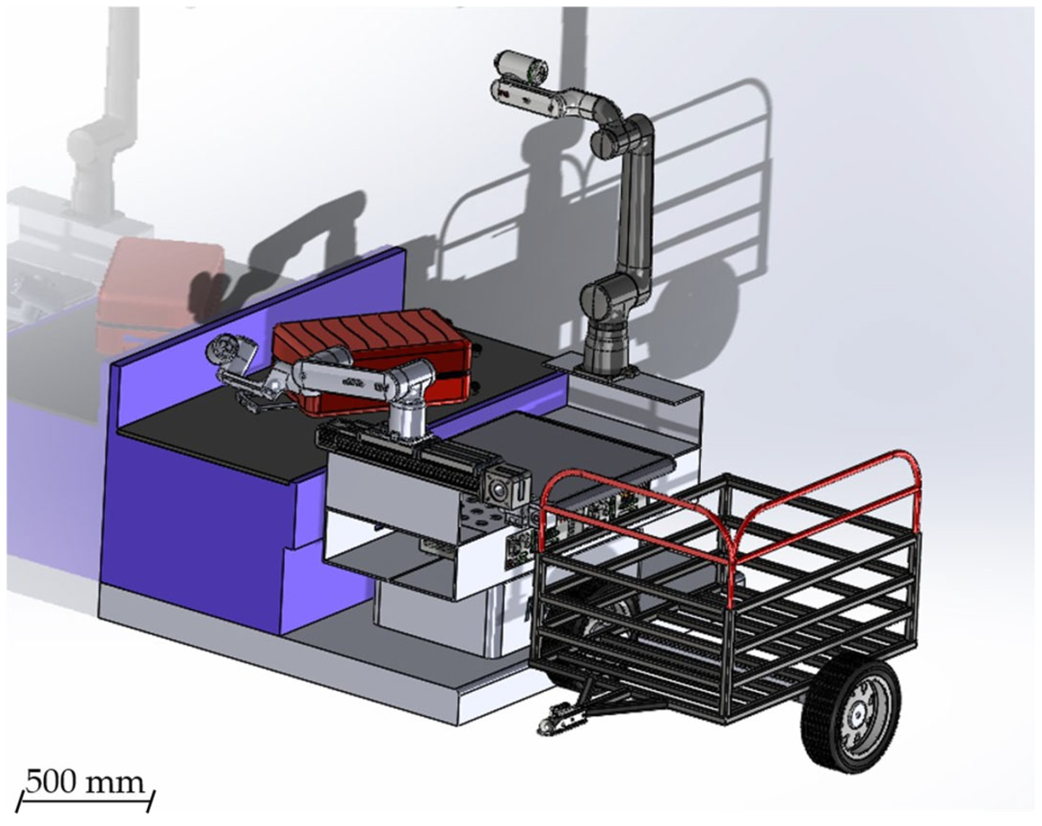
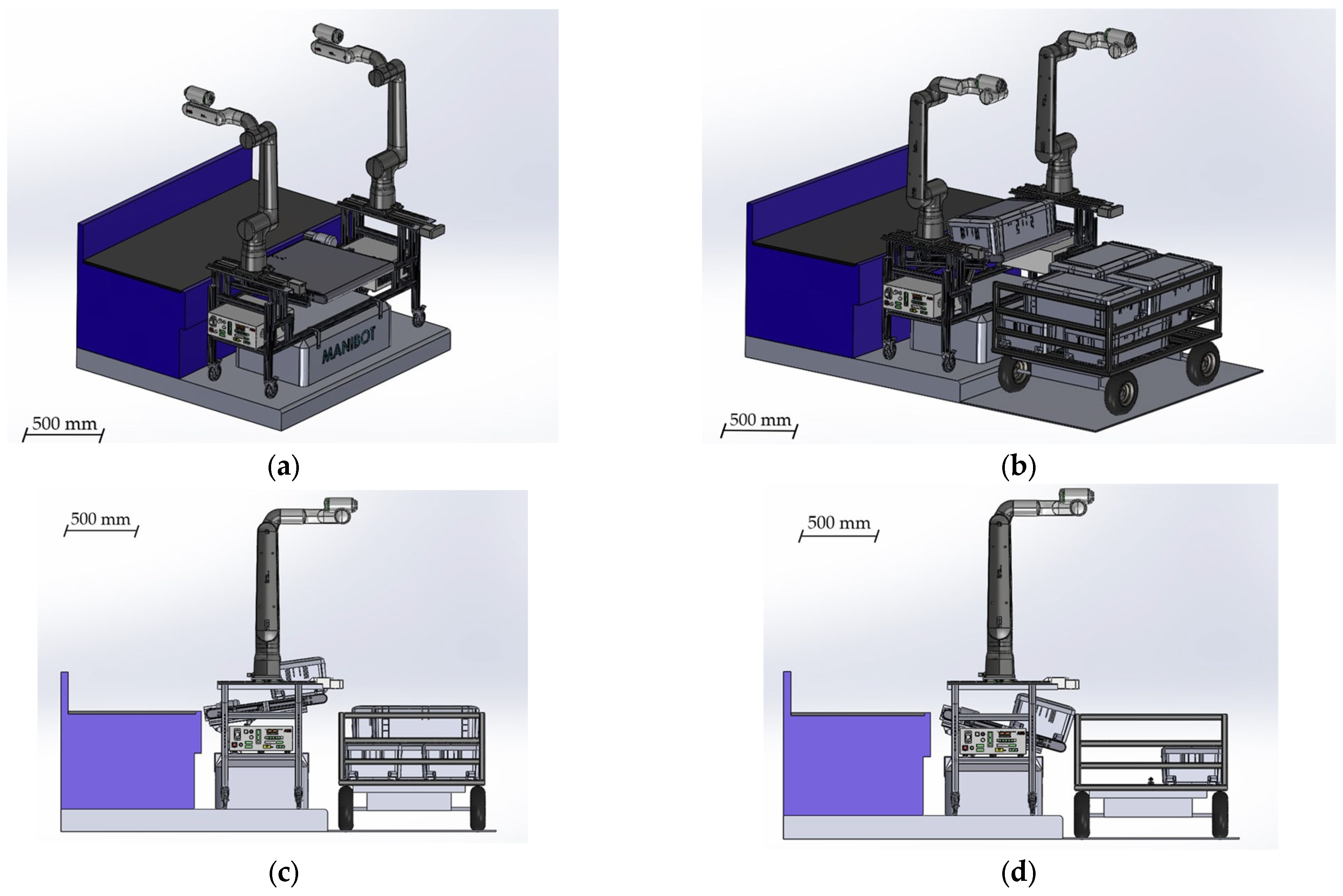
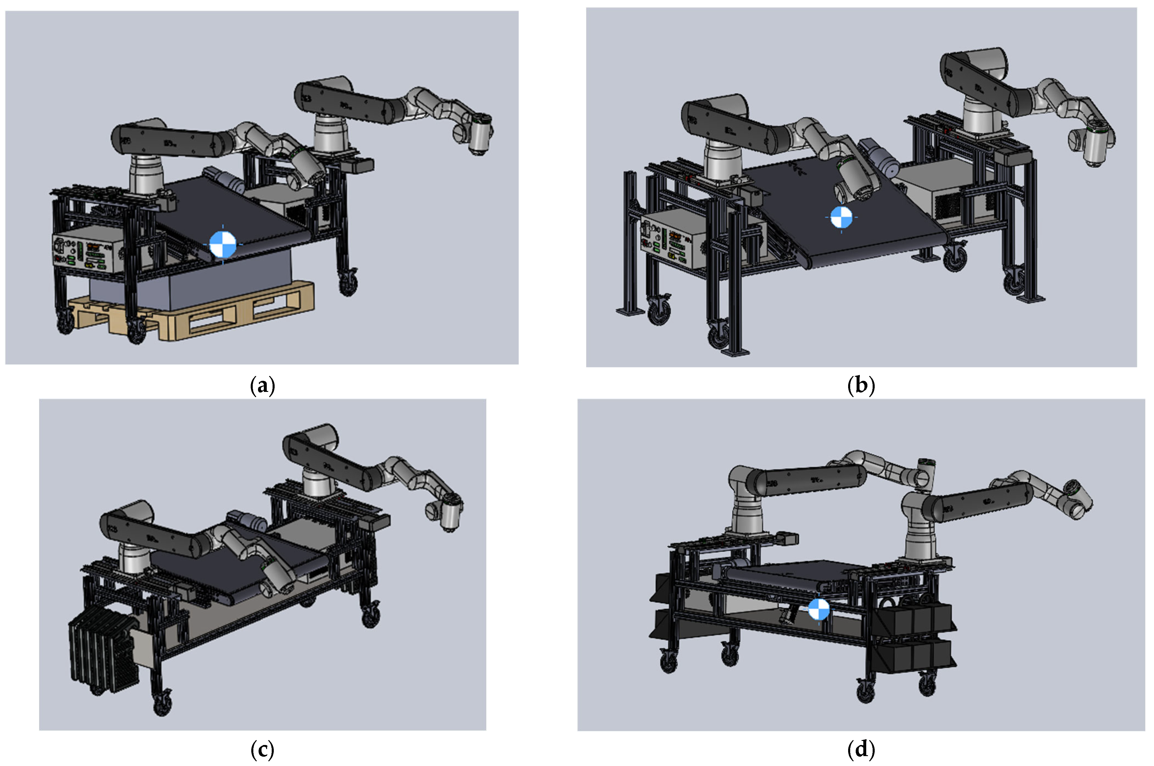
The tenth iteration (
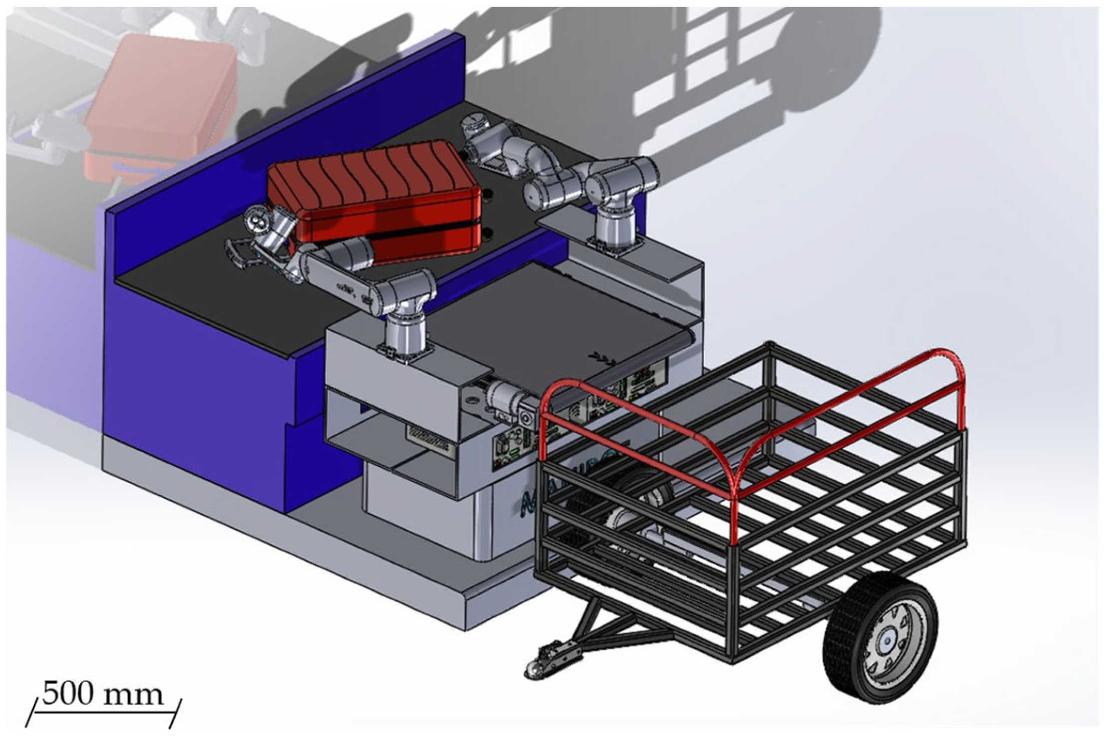
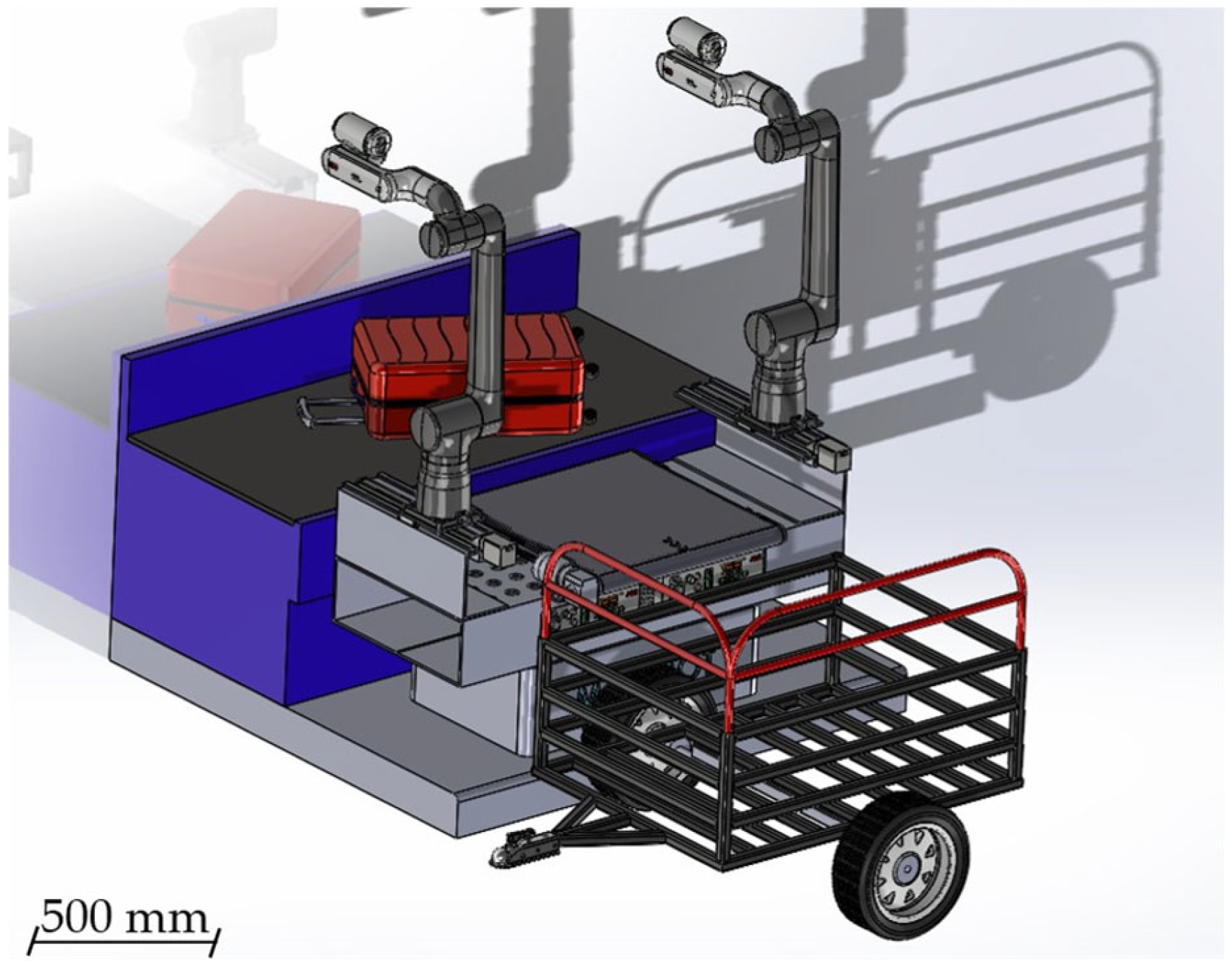
Figure 13a–d) addressed one of the most stringent requirements emerging from the airport scenarios: the need to interact with Fraport’s luggage transport carts. The incorporation of precise cart dimensions revealed that the conveyor system had to deliver objects at multiple heights, prompting a significant mechanical redesign.
To meet this requirement, one longitudinal structural bar was removed to accommodate a lateral tilting mechanism for the conveyor (Objective III). This feature enabled controlled unloading at three distinct vertical levels, replicating real baggage-loading conditions inside the airport cart. The conveyor was designed to operate in both horizontal and inclined configurations, ensuring robust alignment with the manipulators’ linear tracks and workspace envelopes.
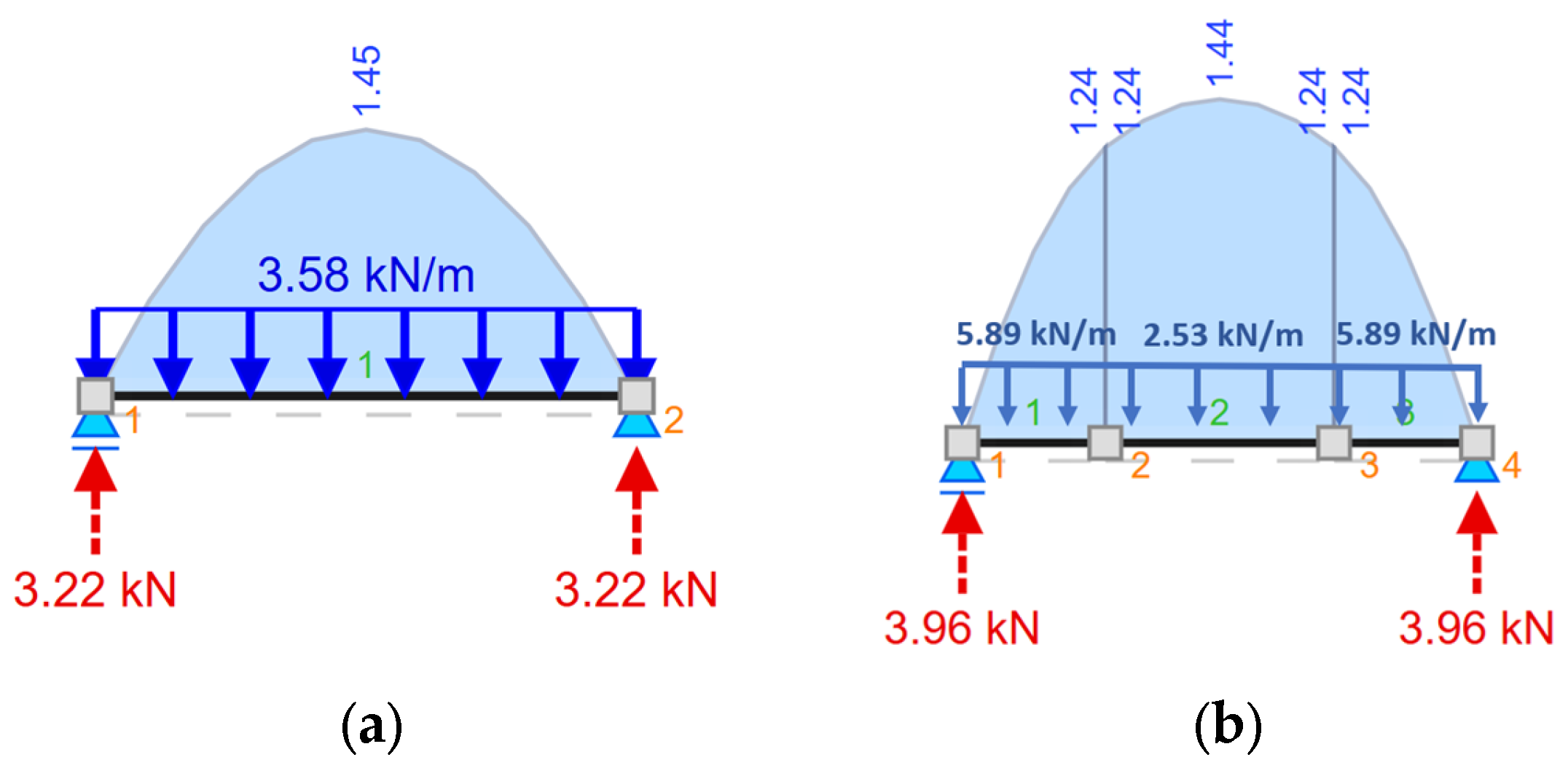
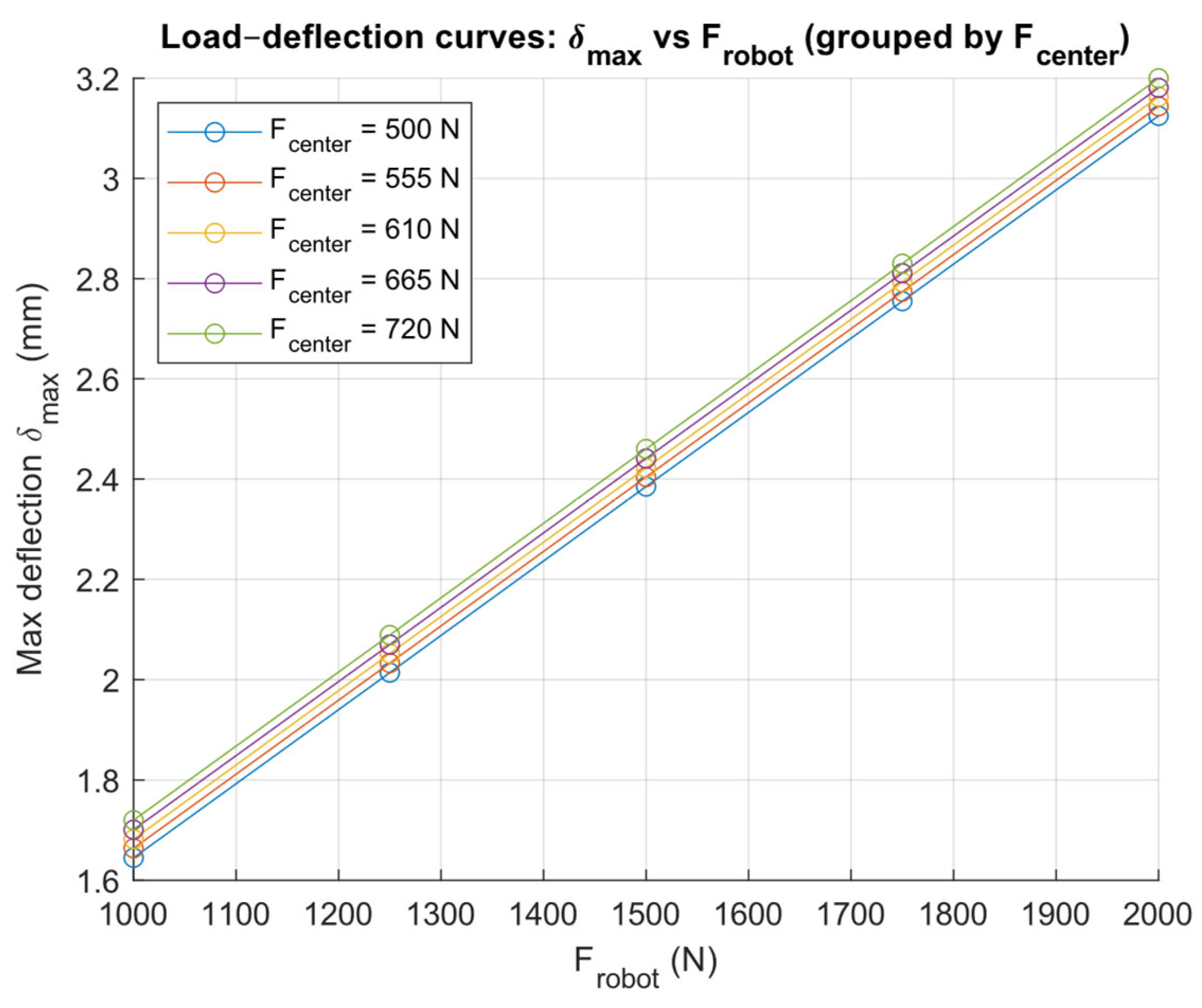
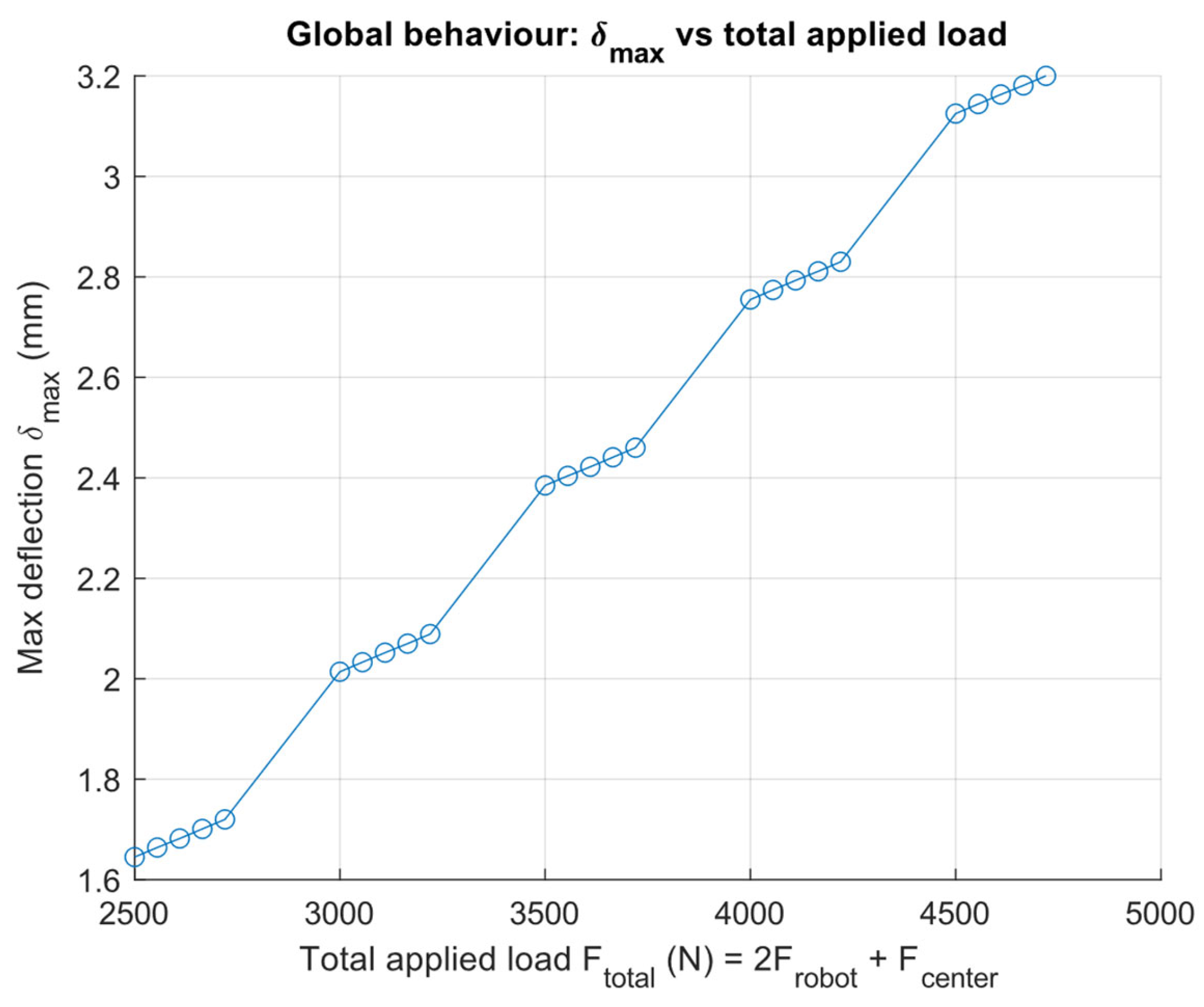
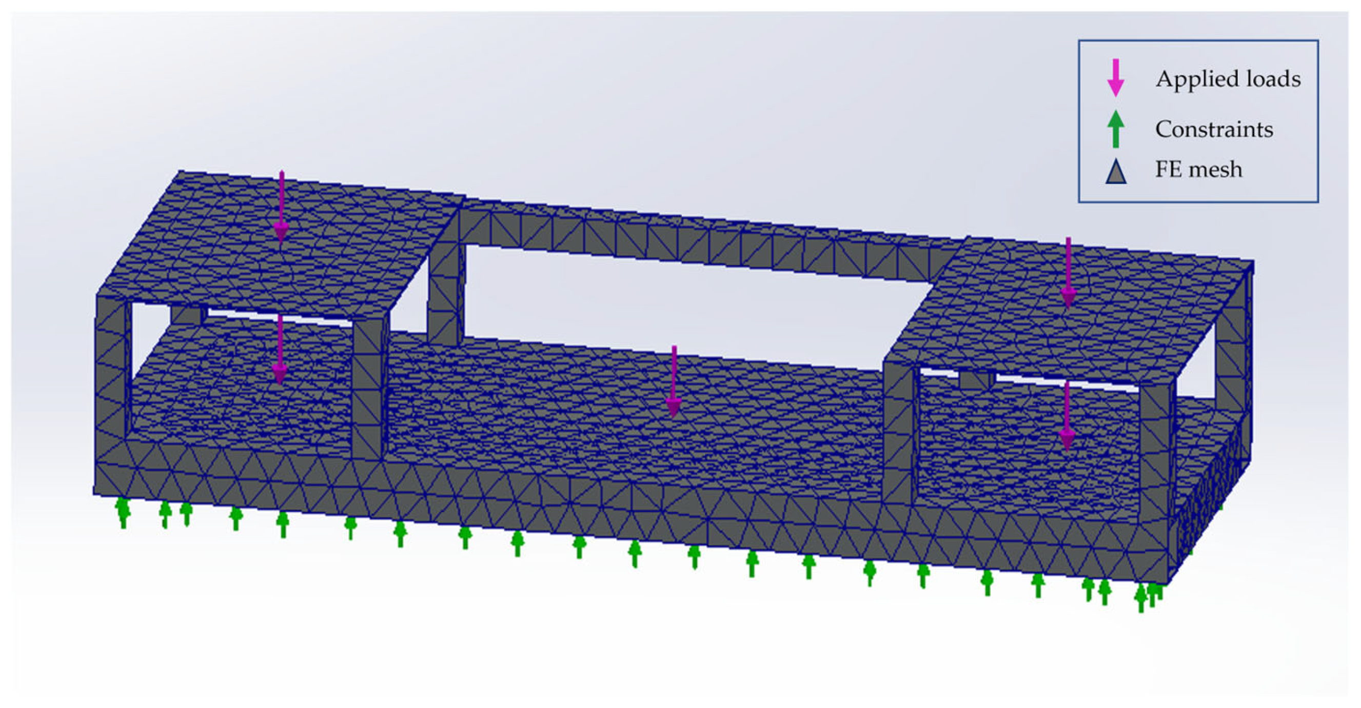
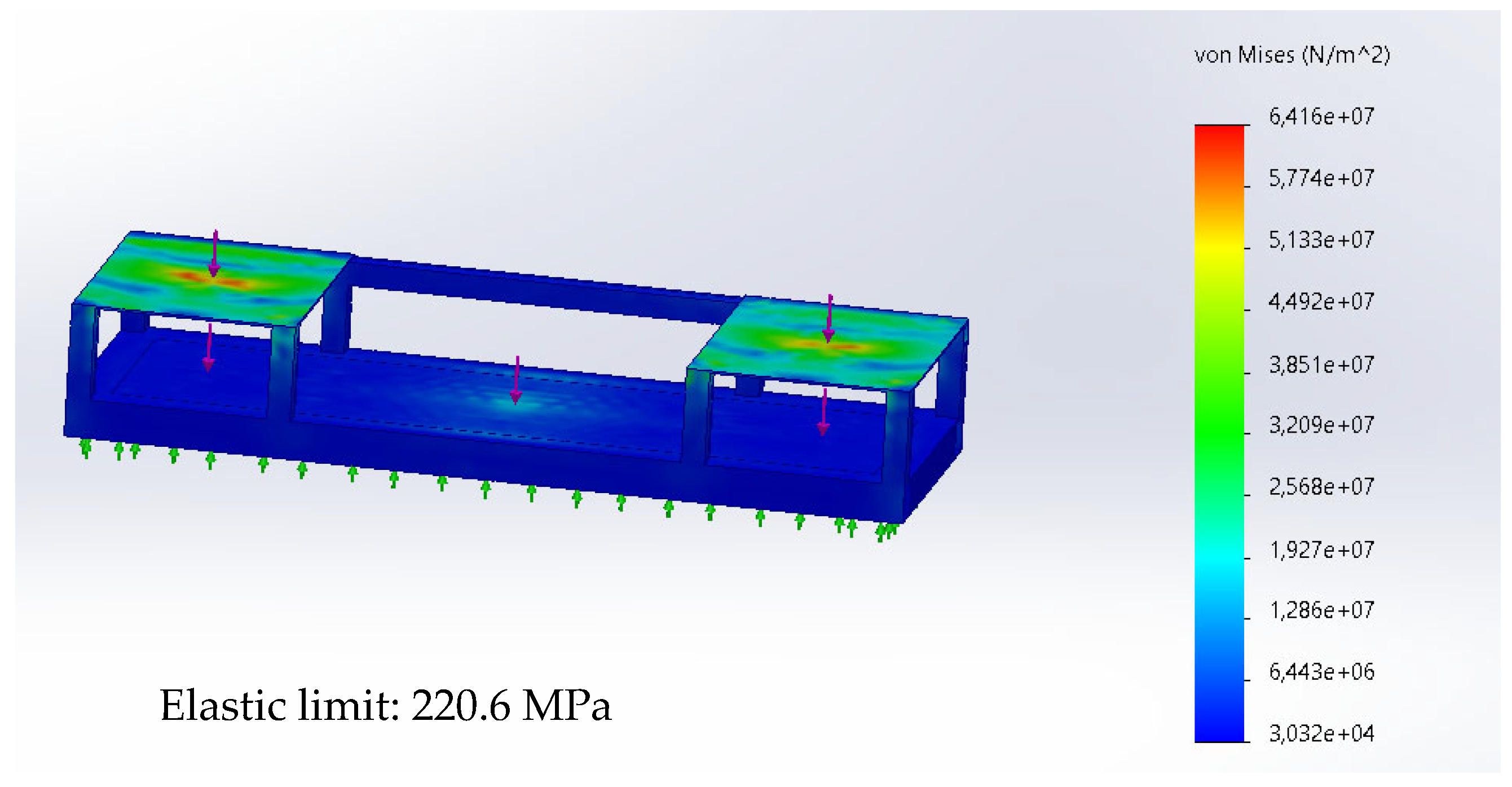
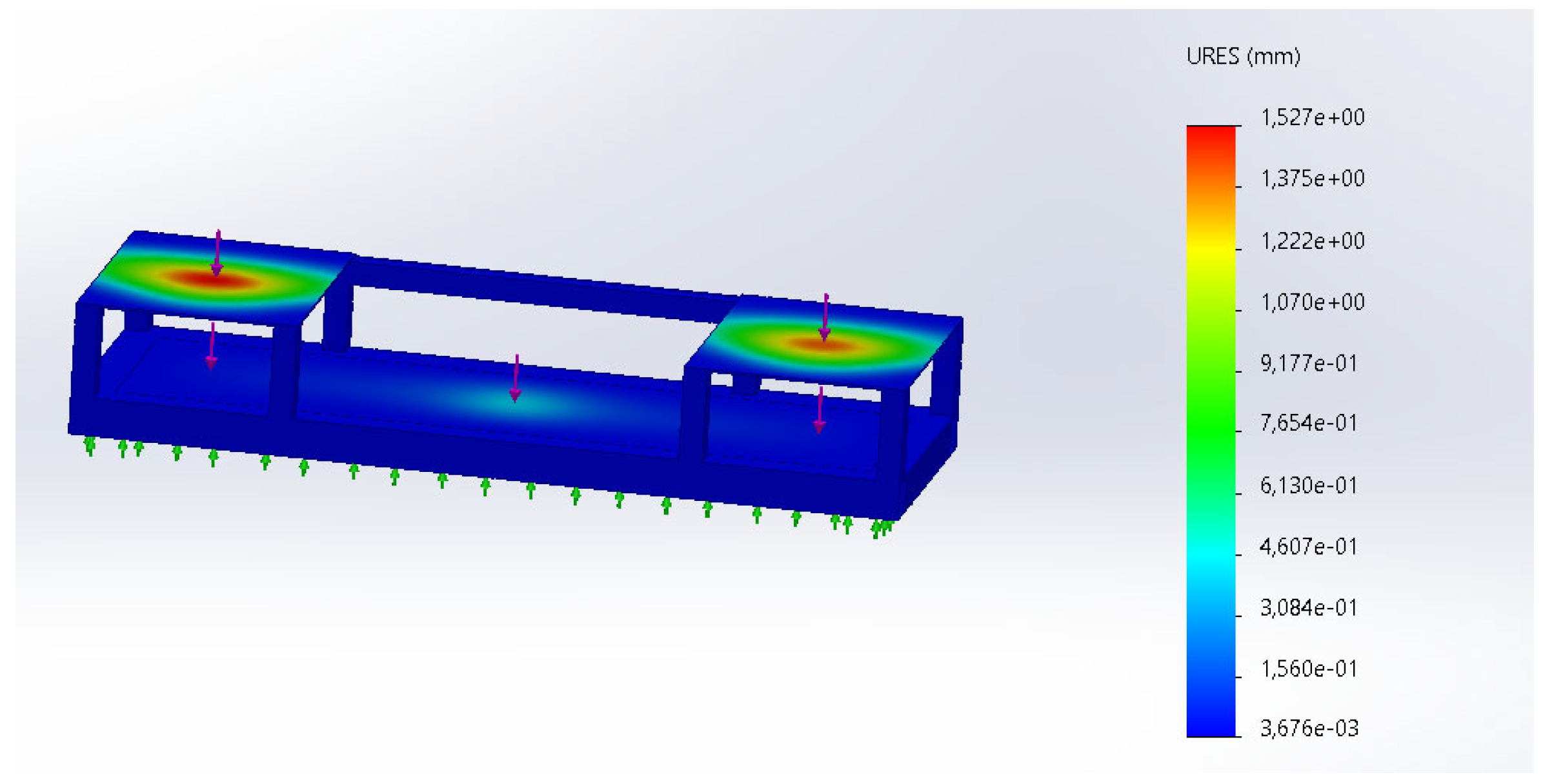
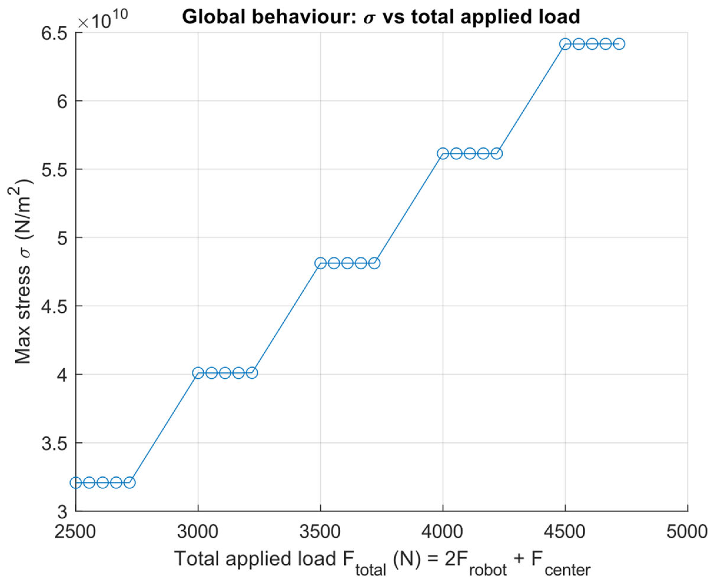
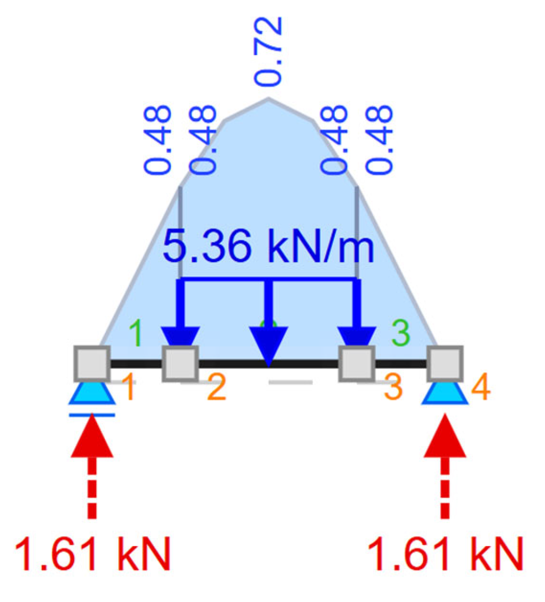
Structural reinforcements were implemented to preserve stability despite the asymmetrical loading introduced by the inclined conveyor. These reinforcements were calculated through additional FEA simulations (Objective II), verifying that the asymmetric loading introduced by the tilted conveyor did not compromise global stiffness or safety margins. The coordination of the robotic arms with the newly angled surface was also validated through simulations, ensuring safe and precise handling at all levels.
All these changes made it necessary to redistribute the devices (Objective IV), and center-of-gravity adjustments were implemented (Objective I) to maintain stability despite the lateral tilt. With this functionality, version 10 bridged the gap between laboratory prototypes and the operational constraints of the airport environment.
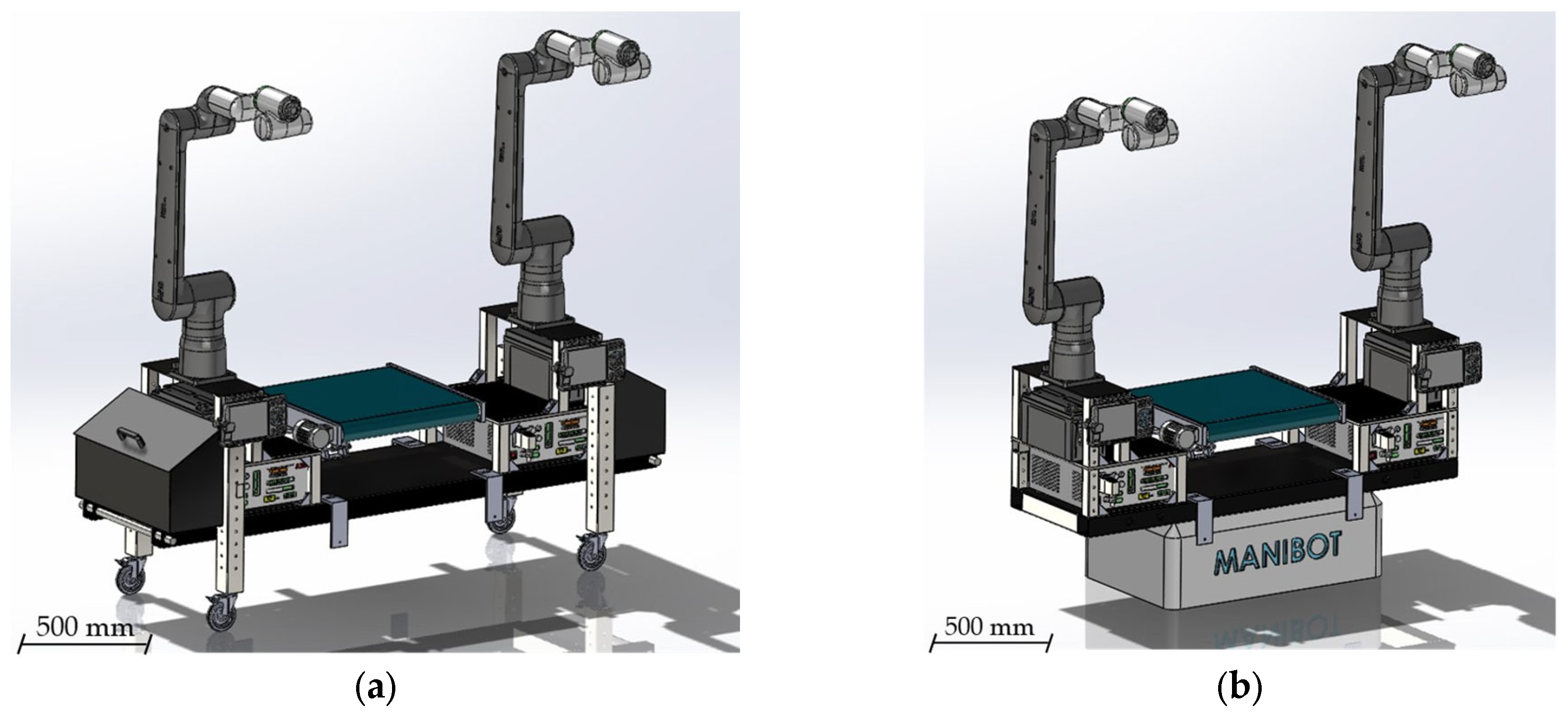
Version 11—Physical validation and transition to steel-reinforced frame.
The eleventh iteration (
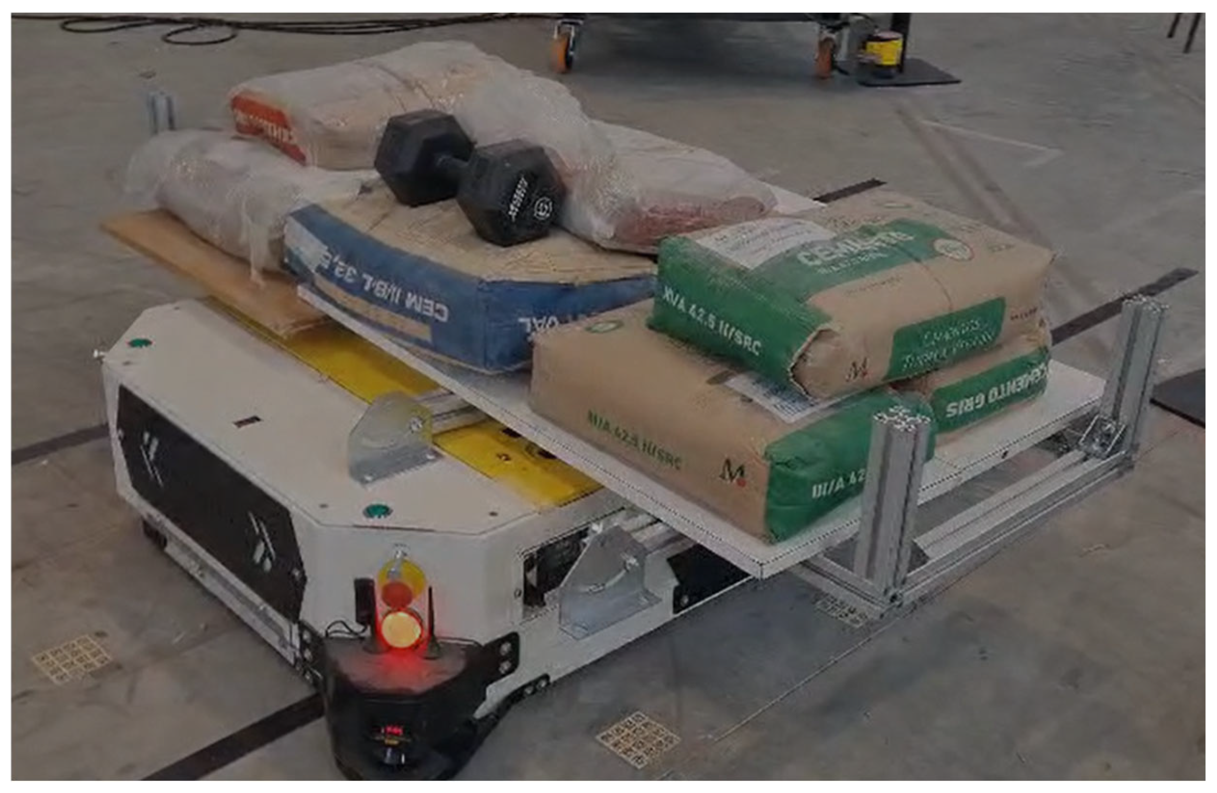
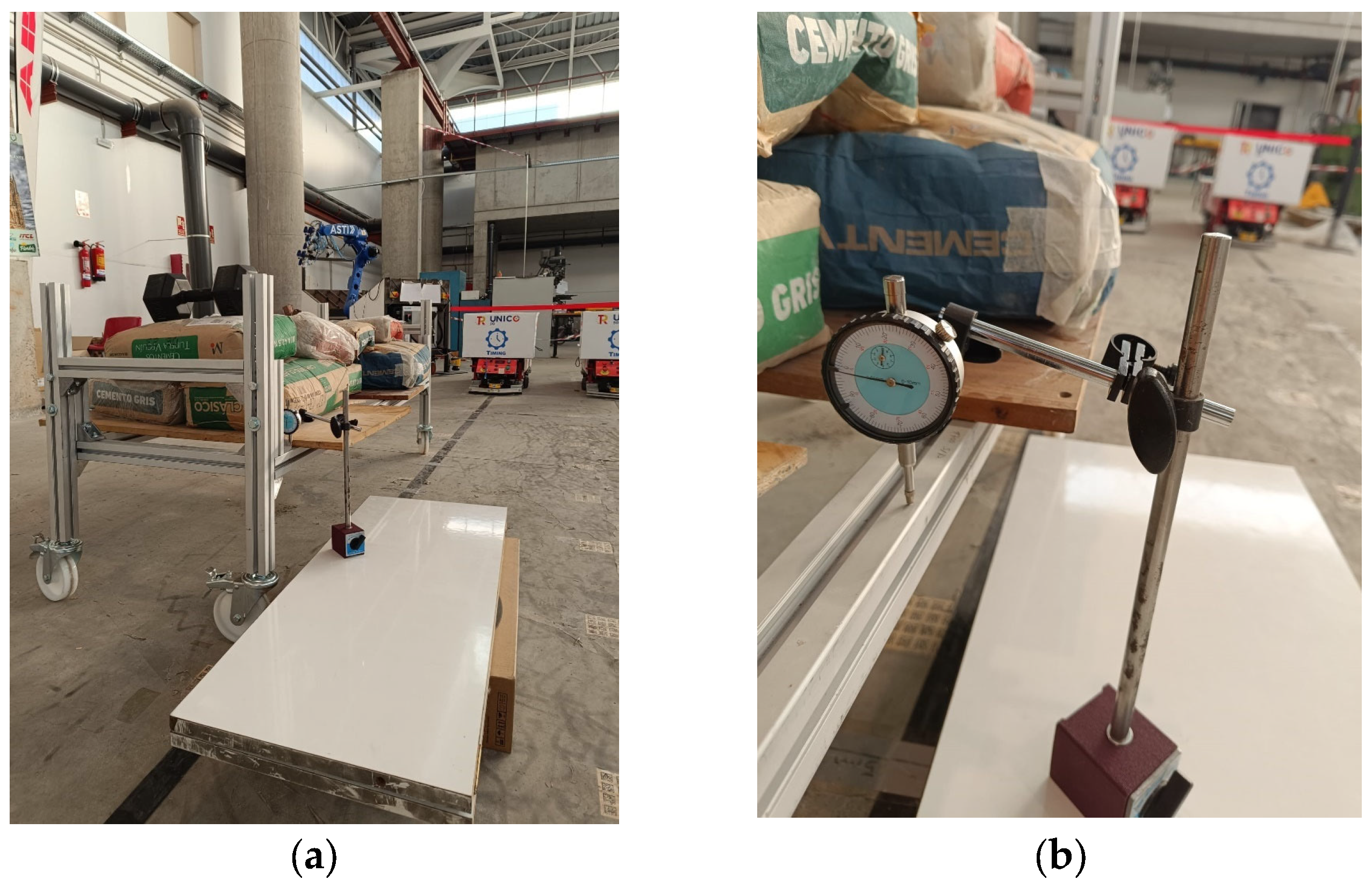
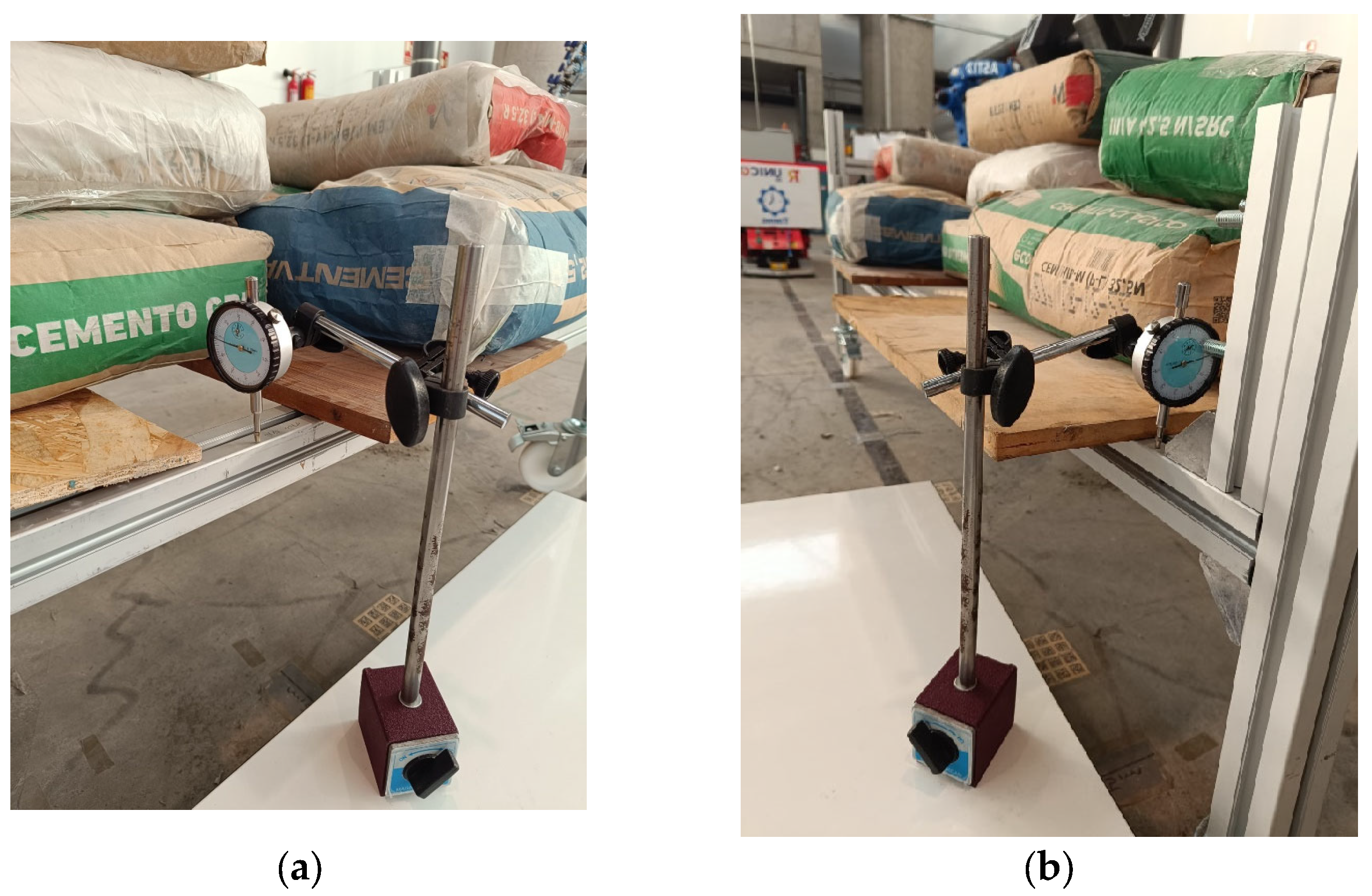
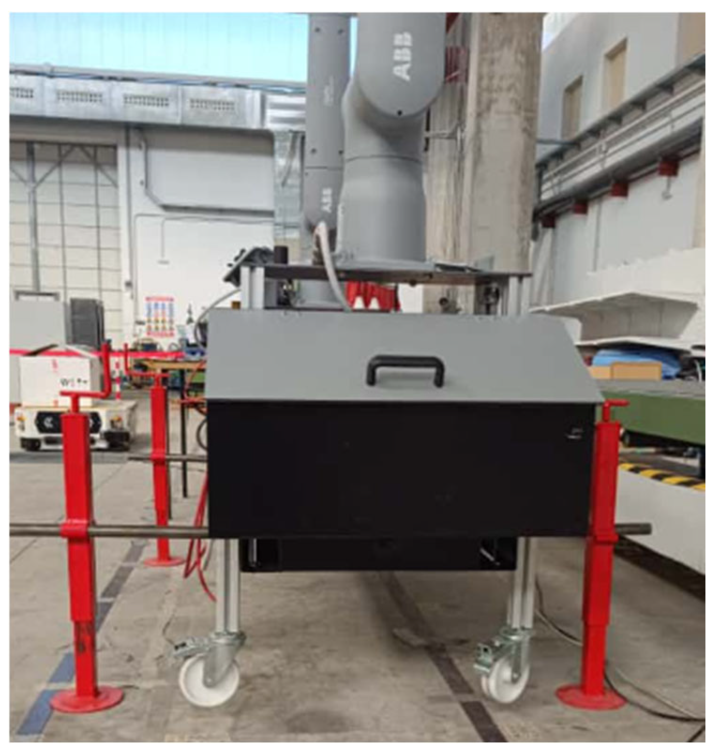
Figure 14) represented a decisive milestone: the transition from purely digital validation to the first physical prototype. A partial assembly, built from aluminum profiles, was manufactured and tested to evaluate rigidity, stability, and dynamic response under simulated loads (Objective II). These experiments revealed critical limitations in structural stiffness and stability, particularly given the projected increase in total mass once both the manipulators and conveyors were fully integrated. Furthermore, range tests showed that the linear motion of the arms provided only marginal functional benefits relative to their high cost and limited applicability, leading to the strategic decision to discontinue their integration in subsequent designs.
Based on these findings, the design strategy shifted to a reinforced steel-tube frame, providing the robustness and safety margins necessary for real-world deployment. The new structure offered superior load-bearing capacity, improved vibration damping, and a significantly reduced risk of tipping during high-payload operations as the COG is lowered (Objective I).
In parallel, a custom conveyor system was developed and integrated, replacing the generic placeholder models of earlier iterations (Objective III). With an extended width of 1800 mm (Objective IV), this conveyor accommodated larger suitcases and enabled smoother transfer to external carts or conveyors. Together, these modifications brought the platform to a new level of maturity, combining physical test results, structural optimization, and operational alignment with the MANiBOT airport scenario.
5.4. Prototype Construction and Assembly
The twelfth and final design iteration (
Figure 15) consolidated the MANiBOT platform into a structurally optimized, modular system ready for experimental deployment. Building directly on the limitations observed during physical testing, this version introduced reinforced 80 mm square steel profiles for the primary load-bearing elements. The enlarged cross-section significantly improved stiffness and mechanical robustness, ensuring reliable operation under dynamic conditions such as rapid manipulator movements or payload handling at extended reaches.
A second major innovation of this version was the incorporation of a dedicated lower technical compartment. This newly designed volume provided safe and accessible housing for essential electronics, including power supplies, communication units, controllers, and sensors. By internalizing these subsystems, the platform achieved cleaner cable routing, enhanced protection, and simplified maintenance. In addition, the redistribution of mass toward the lower frame contributed to a lower center of gravity, directly improving stability during mobile operation and interaction with external objects such as luggage carts.
Weighing 437.3 kg, the system guarantees stability against accelerations and dynamic stresses. The center of gravity was deliberately adjusted to reduce tipping risks and improve maneuverability.
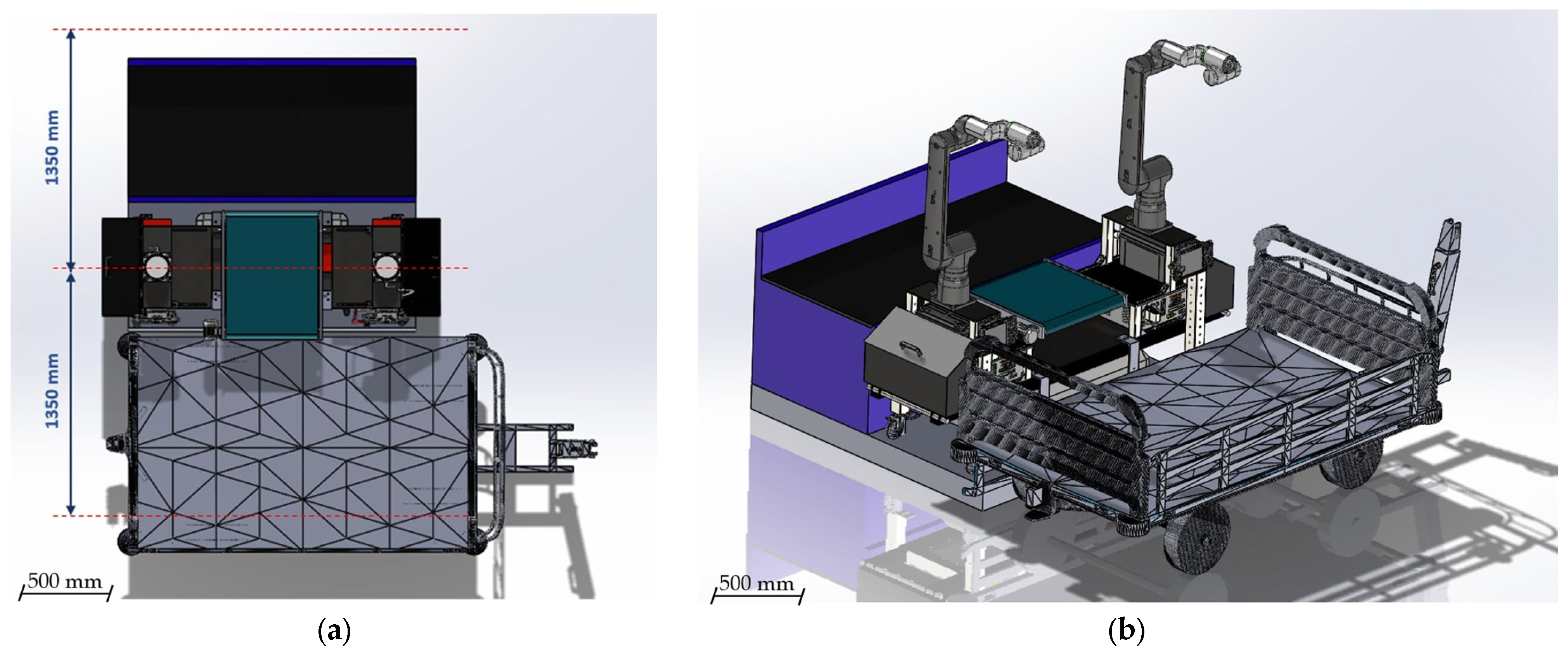
From a workspace perspective, the platform’s geometry was optimized to maximize the overlap of the manipulators’ operational ranges. Both simulations and physical analyses confirmed the absence of collisions during collaborative operations, even when the arms work simultaneously on the same object. Each manipulator can reach up to 1 m beyond the platform boundaries, covering vertical ranges from 0.5 to 2.5 m. This enables the system to interact effectively with carts, conveyors, shelves, and counters at multiple levels.
Furthermore, the design provides dedicated mounting space for all essential computational resources, including three NUCs, two Jetson devices, and one industrial-grade PC, which collectively support the perception, planning, and control layers of the system.
Functionally, the twelfth iteration retained all major advancements from previous versions: the extended-width tilting conveyor, side compartments, and universal AMR mounting interfaces. At the same time, it created new opportunities for scalability, as the technical compartment allows for the integration of additional devices without compromising accessibility or structural integrity.
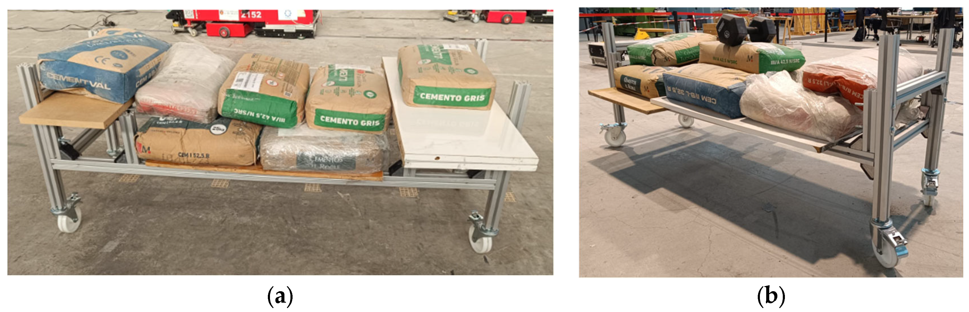
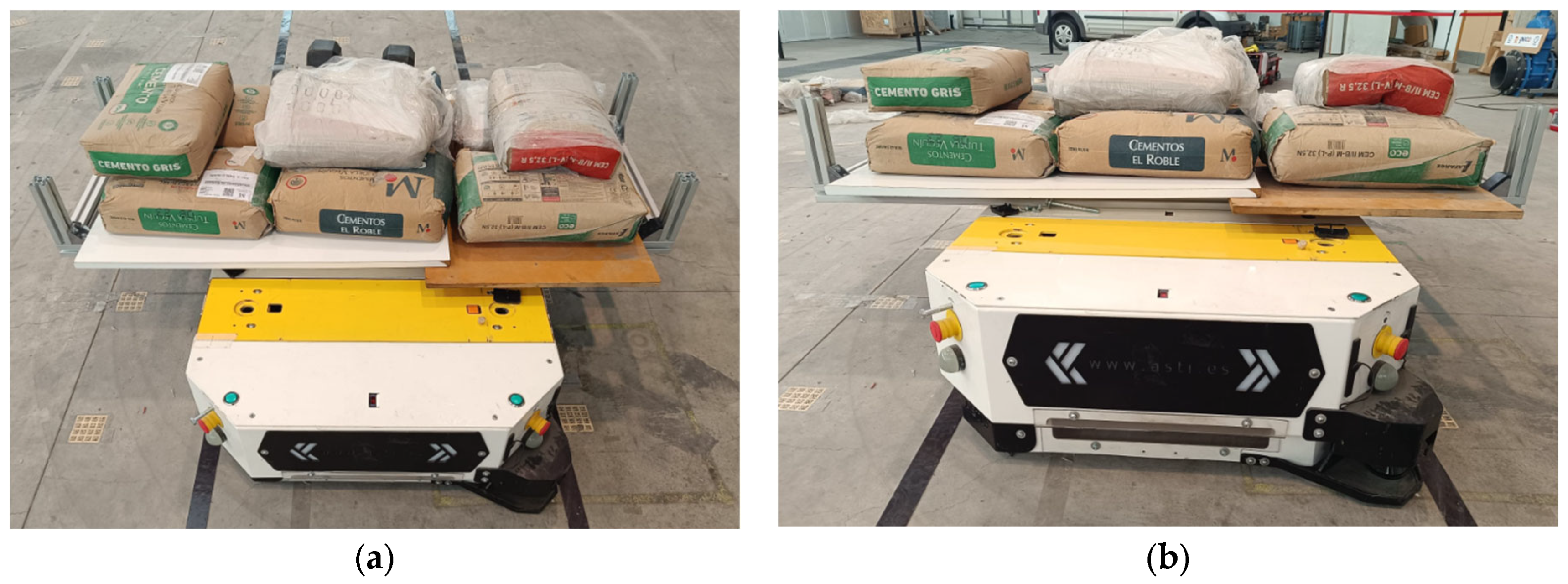
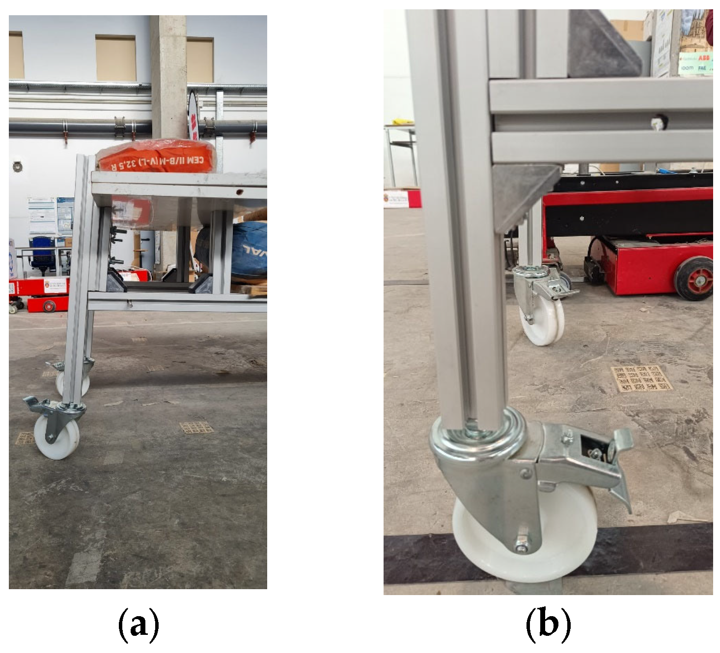
To complement the presentation of the final platform design, additional diagrams have been included to illustrate both the overall reach of the manipulators and the interaction of the platform with the airport trolley (
Figure 16a,b).
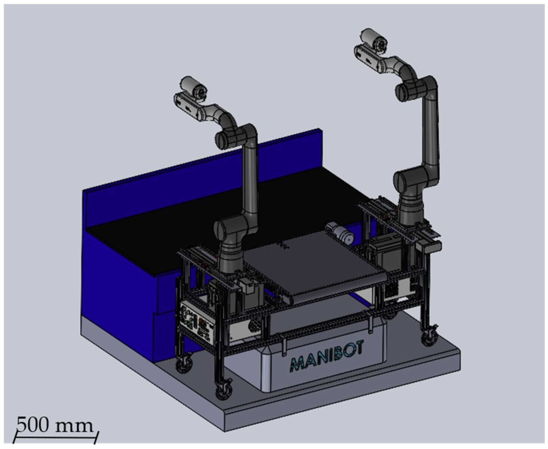
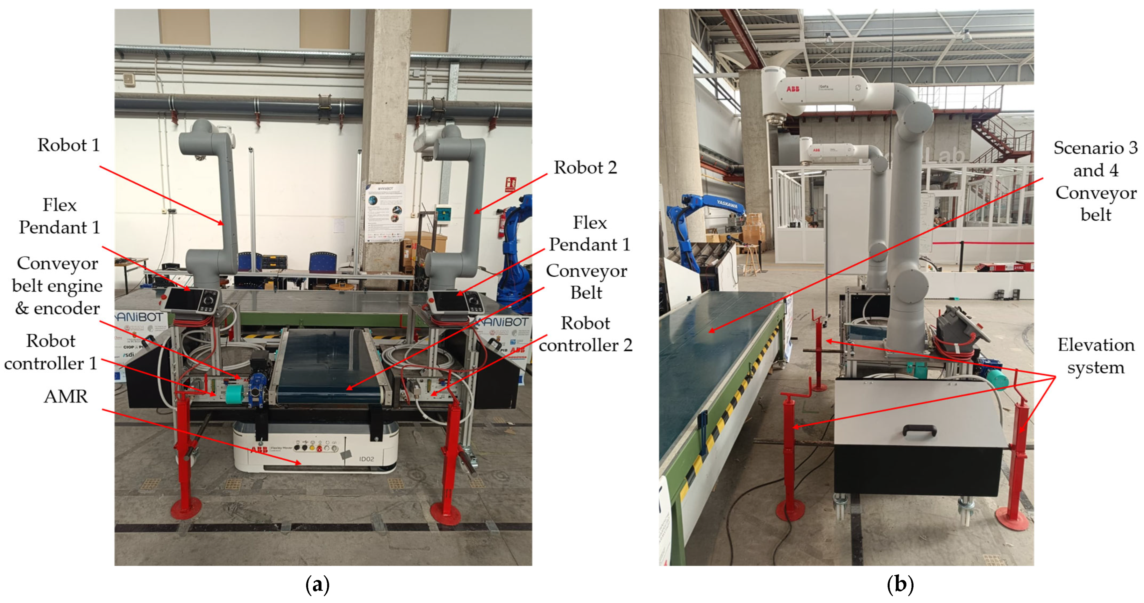
Figure 17 shows the fully assembled MANiBOT prototype. This laboratory-ready platform integrates all structural and functional components—dual GoFa 12 manipulators, tilting conveyor, reinforced steel frame, and technical compartment—mounted on the AMR base. The image provides a direct view of the final system, bridging the iterative design process with the physical prototype now prepared for experimental validation.
In parallel, a summary table has been added to explicitly relate the functional requirements defined in
Section 3 with the design features implemented throughout the iterative development process. For each requirement, the table indicates whether and how it is fulfilled in the final configuration of the MANiBOT platform. This structured analysis provides a direct link between the original project objectives and the mechanical decisions adopted, demonstrating that the resulting system not only meets but, in several cases, exceeds the operational demands identified in real-world scenarios. For clarity and readability,
Table 2 presents two representative requirements as illustrative examples of the proposed design methodology. The complete and detailed version of this table, including all functional and design requirements, is provided in
Appendix A.2 (
Table A2).