1. Introduction
Suspension as a component of the vehicle significantly improves the vehicle‘s driving stability. When running on a rough road, the vibration of the truck is generated due to the excitation from the road, which is then absorbed by the suspension and transmitted to the vehicle body. This is especially evident for a mining dump truck, which often runs on an unpaved road, and the range of vehicle vibration, acceleration, and velocity is usually very wide [
1]. The inherent characteristics of hydro-pneumatic suspension enable it to address critical issues for mining dump trucks, such as uniform load distribution, reduced braking distance, extended service life of brakes and tires, and reduced maintenance costs for the chassis and body. These advantages make it particularly suitable for harsh operating environments typical in off-highway mining applications.
Currently, passive hydro-pneumatic suspension is the most widely used hydro-pneumatic suspension on the market. However, owing to the fixed structure of passive hydro-pneumatic suspension, the inhibition effect on vehicle vibration is limited and is unable to overcome performance limitations with fixed parameters, which only suppresses vehicle vibration by optimizing some parameters.
For instance, multi-objective optimization algorithms can be employed to jointly optimize key parameters of the hydro-pneumatic spring, such as the initial gas charging pressure and effective gas volume, in order to achieve a balanced trade-off between ride comfort and handling stability [
2,
3]. The parameters of the friction model can be identified using velocity and pressure measurements in combination with piecewise linear approximation techniques [
4]. Alternatively, to improve the vibration isolation performance of conventional passive hydro-pneumatic suspensions, the nonlinear stiffness characteristics can be equivalently linearized using statistical linearization methods [
5], or structural modifications can be introduced by means of stiffness matching to realize quasi-zero-stiffness characteristics, thereby enhancing low-frequency vibration isolation performance [
6]. Furthermore, considering the inherent nonlinear damping behavior, some studies have experimentally investigated the effects of different damping orifice diameters and determined the optimal orifice sizes under both unloaded and fully loaded operating conditions [
7].
Therefore, experts and scholars have started to study semi-active/active hydro-pneumatic suspension with adjustable parameters to further improve the dynamic performance of construction vehicles. The active hydro-pneumatic suspension can be controlled by refilling from external fuel sources to adjust the dynamic journey of the suspension. Active control ensures that the wheels can adapt to the road surface as much as possible, while ensuring that the overall performance requirements of the vehicle are met.
Colombo et al. [
8] targeted the problem of load balancing control of a tractor cab equipped with a hydro-pneumatic suspension and designed a linear continuous controller that factors in drive time lag and model uncertainty, and verified the validity of the method through experiments. Ali et al. [
9] created a predictable system performance of hydro-pneumatic suspension for large dump trucks where the performance of the suspension degrades over time, enabling the scheduling of appropriate maintenance or replacement to the improvement of the safety and efficiency of the vehicle system. Awad et al. [
10] designed a hydro-pneumatic energy collection suspension system incorporating a generator and optimized the PID control parameters for regulating the variable load resistance external to the generator using a particle swarm optimization algorithm, which achieved optimum vehicle ride comfort under this system. Fath et al. [
11] proposed an improved skyhook damping control strategy, in which a balanced relationship between the suspension damping and skyhook damping was achieved, thereby avoiding abrupt variations in skyhook damping force that could lead to hydraulic oil impact and excessive noise. Choi et al. [
12] presented a semi-active hydro-pneumatic suspension designed for agricultural tractor cabins and established an accurate experimental testing methodology to characterize the suspension dynamic behavior by varying the excitation current and velocity conditions. Li et al. [
13] developed and experimentally validated a mathematical model of the spring–damper unit for a dual-chamber semi-active hydro-pneumatic suspension. Abut et al. [
14,
15,
16] systematically explored the application and evolution of active control based on intelligent optimization algorithms in vehicle suspension systems. The studies were all based on a one-quarter car model, using the Lagrange–Olaf method to establish dynamic models, designing linear-quadruple-Gaussian and fuzzy linear-quadruple-Gaussian controls, fuzzy logic control based on harris hawks optimization algorithm, and fuzzy-LQR control algorithms, significantly improving vehicle driving comfort and handling stability.
To address the inherent nonlinearities, parameter uncertainties, and disturbances induced by complex driving conditions in suspension systems, the application of modern control theory has become increasingly widespread and continues to deepen. Modern control theory encompasses a series of core methodologies, including sliding mode control (SMC), model predictive control (MPC) [
17], active disturbance rejection control (ADRC) [
18], fuzzy control [
19], linear quadratic Gaussian (LQG) control [
16], neural network–based control, and adaptive control strategies. In recent years, in order to further enhance control performance and system robustness, hybrid control architectures that integrate the advantages of different control strategies have emerged as an important research direction, such as combining the optimization capability of MPC with the strong robustness of sliding mode control, or embedding LQR control within a fuzzy adaptive control framework. Compared with classical PID control [
20] and traditional schemes such as linear quadratic regulator (LQR) control, these modern approaches and hybrid strategies demonstrate significant theoretical superiority and engineering potential in handling nonlinear and strongly coupled systems [
21], achieving multi-objective dynamic coordination, and coping with model uncertainties and external disturbances, and have thus become a key theoretical foundation for the design of high-performance active and semi-active hydro-pneumatic suspension systems. Viadero-Monasterio et al. [
22,
23,
24] systematically investigated the problems of active suspension control systems to improve vehicle driving safety and comfort, designed dynamic output feedback controllers to ensure system stability, and designed the controllers with executive failure in mind. It also designed a robust state feedback event-triggering fault tolerance controller and evaluated the characteristics of vibration suppression control performance under different road conditions.
Although studies on control strategies for active hydro-pneumatic suspensions have yielded promising results, the field is still in its infancy. Due to the non-linearity of the hydro-pneumatic suspension, the variability and randomness of the driving surface, a single control strategy is no longer able to achieve the optimal overall performance of the vehicle under different operating conditions, and may even lead to deterioration of the system performance caused by mismatch of the control parameters, thus limiting the overall performance of the hydro-pneumatic suspension system. In order to take into account the longitudinal, lateral, and vertical (LLV) dynamics of the vehicle, LLV coordinated control of active hydro-pneumatic suspensions (including optimization of vehicle vertical vibration [
25], pitch vibration, and lateral roll vibration [
26]) needs to be considered to improve ride comfort and handling stability of engineering vehicles.
The coordinated control of longitudinal, lateral, and vertical dynamics is a defining characteristic of the intelligent evolution of commercial and engineering vehicles, garnering significant attention within the research community. More research focuses on the change in vehicle height under different working conditions. Controlling the longitudinal pitch, lateral roll, and vertical vibrations of vehicles under predetermined target variations has gradually become a hot topic in research.
Gomonwattanapanich et al. [
27] proposed an active suspension control strategy based on the linear quadratic Gaussian (LQG) algorithm for ride comfort optimization, which effectively reduced vehicle vertical displacement, longitudinal pitch, and lateral roll motions, thereby achieving efficient suppression of multidimensional vehicle vibrations. Posseckert et al. [
28] addressed the lateral vibration control of railway vehicles operating under harsh track conditions and proposed an MPC strategy based on track preview information, in which active lateral secondary suspension was used to compensate for future disturbances in advance, leading to a marked improvement in lateral ride comfort. Liu et al. [
29] proposed an integrated control scheme oriented toward ride comfort enhancement, in which vehicle speed trajectories were optimized using dynamic programming and quadratic programming algorithms, resulting in simultaneous improvements in ride smoothness from both vertical and longitudinal perspectives. Wang et al. [
30], based on a high-fidelity multidimensional full-vehicle dynamics model incorporating nonlinear steering and suspension characteristics, developed a hybrid control strategy in which an acceleration-driven damping–skyhook logic was employed for vertical control. This approach significantly improved vehicle handling stability and ride comfort under steering as well as acceleration and deceleration conditions, achieving coordinated optimization of the suspension’s longitudinal and vertical performance. Bai et al. [
31] designed a dual-time-scale model predictive control (MPC) framework in which the coupled control of the active suspension and longitudinal vehicle dynamics was realized. At the short time scale, road preview information was utilized to coordinate suspension actions with longitudinal acceleration, thereby improving both vertical and longitudinal ride comfort. At the long time scale, vehicle speed planning based on Gaussian process regression was implemented, effectively suppressing vertical excitations induced by road irregularities.
Key to the LLV coordinated control of active hydro-pneumatic suspensions is the implementation of an advanced control strategy. The essence of active control is to change the control parameters in real time according to the current driving state, and to adjust the damping and stiffness of the system and suppress the vibration of the body (sprung mass)/wheel (unsprung mass) vibration [
32]. Different suspension control strategies also have respective control effects for achieving LLV coordinated control. Regarding the multi-input and multi-output coupling characteristics in the control process of suspension systems, model predictive control (MPC) solves the controller’s actions by constructing an optimization problem [
33], which can naturally ensure that constraints are satisfied in the optimization problem [
34].
From the above studies, existing research on vehicle dynamics control has primarily addressed longitudinal (pitch-related) and lateral (roll-related) motions in isolation or in a combined longitudinal/lateral manner. However, coordinated control encompassing longitudinal (pitch), lateral (roll), and vertical (vibration) dynamics—termed LLV coordinated control—remains a significant challenge, especially under complex and varying operating conditions. Crucially, most control strategies are designed with fixed parameters, neglecting the substantial influence of varying driving conditions (e.g., speed, payload, terrain). This oversight results in strategies optimized for a single, nominal operating point, compromising their overall dynamic performance, stability, and ride comfort in real-world scenarios where pitch, roll, and vertical motions are strongly coupled.
Hence, the design of an active hydro-pneumatic suspension enabling optimal overall performance in different operating environments has become the research objective of this paper. This paper focuses on the common articulated mining dump truck in engineering vehicles as the research object and researches the LLV coordinated control of active hydro-pneumatic suspension in engineering trucks with the control objective of achieving the optimal coordination of longitudinal (pitch), lateral (roll), and vertical (vibration) dynamics of the active hydro-pneumatic suspension. With the construction of a non-linear model of multi-axle articulated mining dump truck including hydro-pneumatic suspension, the mapping relationship between different driving conditions and the performance requirements of vehicle dynamics is clarified, and an active hydro-pneumatic suspension LLV coordinated control system is constructed for articulated mining dump truck under complex working conditions.
Unlike most existing studies focused on passenger cars or rigid-frame mining trucks, our research specifically targets a multi-axle articulated mining dump truck. This choice is deliberate, as the articulated dump truck represents a more complex and critically relevant engineering vehicle: its unique articulated chassis design introduces severe and dynamically coupled LLV disturbances that are fundamentally more challenging to control than those in vehicles with a rigid frame. These challenges arise from variable heavy loads, operation on unpaved and uneven terrains, and the significant dynamic interaction between the front and rear units (or the tractor and dump body) through the articulation joint during steering and when traversing obstacles. This interaction uniquely exacerbates coupled pitch, roll, and vertical (vibration) motions, creating a control problem distinct from that of single-unit vehicles.
The rest of the paper is organized as follows.
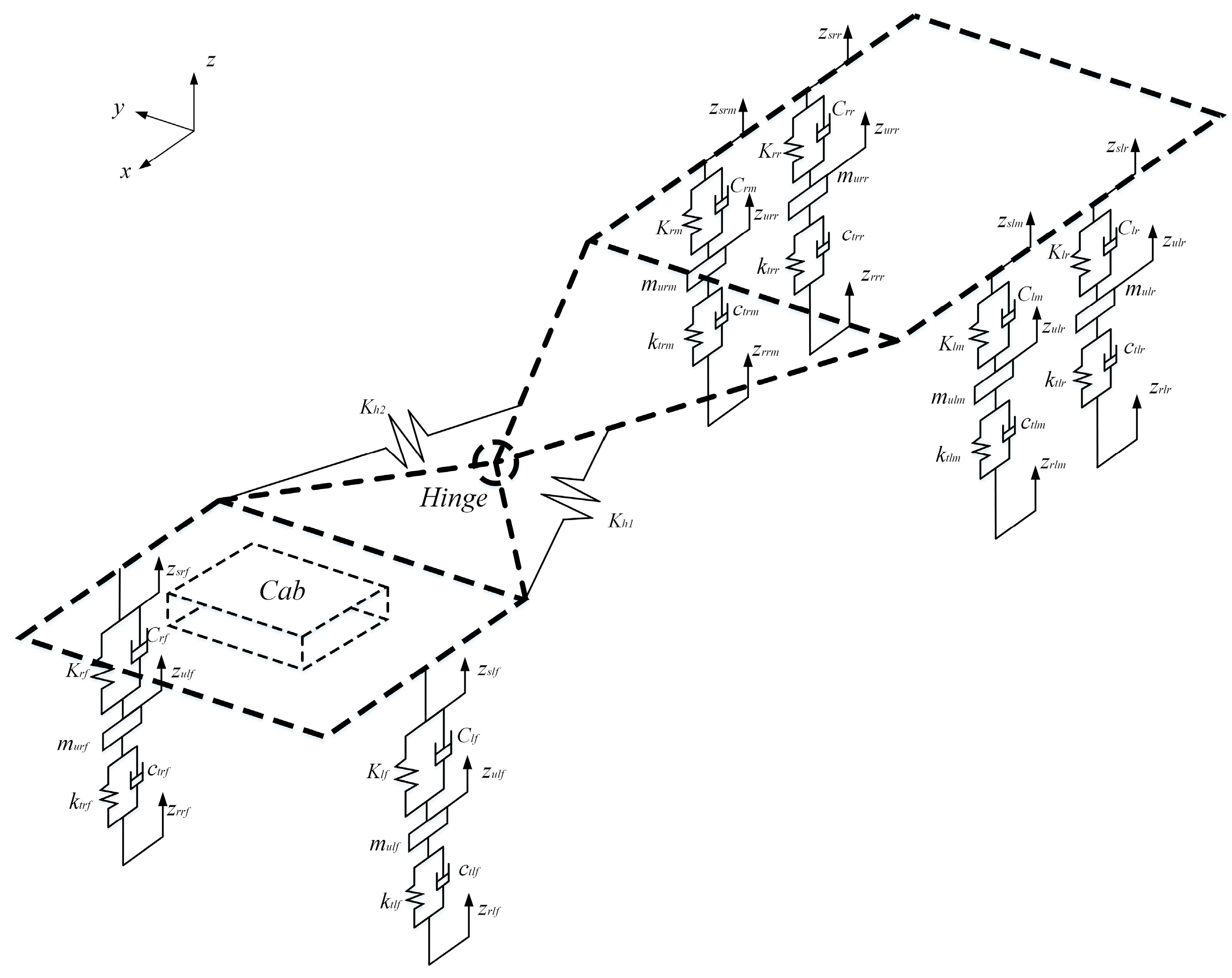
Section 2 analyzes and models the hydro-pneumatic suspension dynamic model and the full-vehicle dynamic model of the articulated mining dump truck. In
Section 3, a longitudinal, lateral, and vertical (LLV) coordinated control architecture for the active hydro-pneumatic suspension is designed based on the MPC approach. The superiority of the active hydro-pneumatic suspension designed based on the model predictive control method in the longitudinal, lateral, and vertical (LLV-MPC) coordinated control effect of the whole vehicle is verified in
Section 4. Finally,
Section 5 provides the general conclusions.
3. Output Force Control Strategy for Hydro-Pneumatic Suspension Based on Model Predictive Control
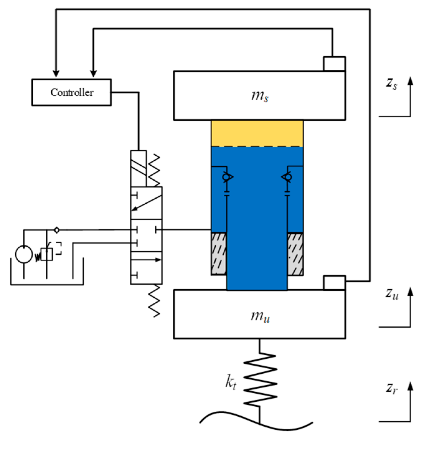
To balance the ride comfort and handling stability of the truck, the active hydro-pneumatic suspension control system takes the longitudinal, lateral, and vertical body accelerations, suspension working stroke, and dynamic tire load as its output variables, and adopts the output force of the hydro-pneumatic suspension system as the control input—further meeting the requirement for rapid response of the active hydro-pneumatic suspension system. Therefore, an MPC controller for the hydro-pneumatic suspension is constructed based on the full-vehicle dynamics model, thus forming the closed-loop control system for the active hydro-pneumatic suspension of the articulated mining dump truck in this section.
3.1. Controller Design-Oriented Modeling of Active Hydro-Pneumatic Suspension Systems
- (1)
Control objective
MPC can only solve optimal control problems in the predictive time domain in discrete form. Discretize the continuous state space equation with the sampling time
Ts = 10 ms and dominant vibration cycles 1–2 Hz. Select state variables
, random road speed
, control input defined as
u(
t) =
iu, and control output force
. According to the suspension state estimation method in the literature [
36,
37,
38], the result is obtained as follows:
where
Cs is the flow coefficient of the damping hole;
kt is the tire stiffness;
ct is the tire damping coefficient of the corresponding wheels;
zr is the vertical road surface excitation.
In quarter-vehicle suspension control studies, the body acceleration (vertical), suspension working space, and dynamic tire load are typically selected as the three dynamic evaluation indicators to characterize the vehicle’s ride comfort, handling stability, safety, and suspension travel in ¼ vehicle suspension control studies. Body acceleration (vertical) is used to characterize ride comfort; suspension working space is used to limit the travel of the suspension to avoid the impact of the suspension on the limit block, which reduces the service life and the ride comfort, and dynamic tire load is used to characterize the degree of damage to the road, and the smaller its value, the lower the degree of damage to the road surface and the better the handling stability and safety of the vehicle.
Since the mining dump truck studied in this paper is an articulated mining dump truck, its front and rear bodies are articulated rather than rigidly connected. Therefore, the measured three-axis acceleration signals correspond to the direction vectors of the front and rear axles in the longitudinal, lateral, and vertical directions, respectively. The pitch angle, roll angle, and vertical acceleration can then be converted from these three-axis acceleration signals, which are also used as evaluation indexes for the vehicle’s longitudinal, lateral, and vertical (LLV) coordinated control in the simulation analysis. Therefore, the root mean square (RMS) values of the longitudinal, lateral, and vertical accelerations at the sprung mass centers of the front and rear truck bodies are selected as the core evaluation indexes for the vehicle’s LLV coordinated control. This selection is not only easy to implement in practical measurements, but it can also characterize the vibration characteristics of the front and rear sprung masses of the entire system well.
The RMS value of each evaluation index can better reflect the results of the index in the suspension evaluation. Therefore, the RMS value of the three-axis accelerations to reduce the sprung mass of the front axle cab, the reduction in the impact probability of the limiting block at both terminals of the suspension, and the reduction in the RMS value of the wheel dynamic tire load of the articulated truck are taken as the control objectives of the MPC controller in this paper, and further design the system objective function based on quadratic form.
In summary, the performance indicators of the LLV coordinated controller are defined as the front axle cab three-axis acceleration [, , ], six suspension working space [zulf-zslf, zurf-zsrf, zulm-zslm, zurm-zsrm, zulr-zslr, zurr-zsrr], and each dynamic tire load [ktlf(zulf-zrlf), ktrf(zurf-zrrf), ktlm(zulm-zrlm), ktrm(zurm-zrrm), ktlr(zulr-zrlr), ktrr(zurr-zsrr)], while considering the deformation of the tire during normal operation to maintain its stiffness. Therefore, for the dynamic load of the wheels, the control objective can also be simplified as [zulf-zrlf, zurf-zrrf, zulm-zrlm, zurm-zrrm, zulr-zrlr, zurr-zsrr], and the weight coefficients of each target, including ψa, ψsws, and ψdtl.
- (2)
Constraint optimization
During operation, the primary objective of the system is to achieve ride comfort and handling stability of the vehicle, namely, minimization of the body acceleration, roll angle, pitch angle, suspension working space, and wheel dynamic tire load. A mathematical expression for the objective function is defined based on the system control objectives, which consists of multiple cost terms. The purpose of LLV coordinated control is to minimize the following objective function:
where
Jride represents a nonlinear quadratic function that considers the comfort requirements of vehicles within the predicted range:
where
qride represents the weighted output error of the vehicle acceleration system. Smoothness is usually represented by vehicle acceleration. Therefore, the penalty function penalizes the difference between the body acceleration and the expected value of the sprung mass, which is set to zero in the prediction layer.
Jload represents a nonlinear quadratic function of the degree of damage to the road surface:
where
i∈[
fl,
fr,
ml,
mr,
rl,
rr],
qload represents the weighted output error of the dynamic tire load system. Maintaining constant wheel contact with the road surface is also important for improving vehicle maneuverability and driving safety.
Jpitch represents the nonlinear quadratic function of vehicle pitch motion:
where
qpitch represents the weighted output error of the vehicle pitch acceleration system.
Jroll represents a nonlinear quadratic function that considers vehicle roll on the front and rear axles:
where
where
qrollfront represents the weighted output error of the front axle body roll angle acceleration system, and
qrollrear represents the weighted output error of the rear axle body roll angle acceleration system.
The suspension force generated by the active hydro-pneumatic suspension (AHPS) is inherently limited in practical systems. Therefore, this limitation should also be considered in the form of constraints in the design of the MPC controller to ensure that the optimal value of control solved is within the range of suspension capacity range.
The active hydro-pneumatic suspension output force is designed as the control value of the MPC controller in this paper, and the output force of the hydro-pneumatic suspension consists of two parts: the adjustable damping force and the gas elasticity force, in which the elasticity force varies with the change in the adjustment of the damping force, and therefore there are certain constraints on the forces generated by each component.
The damping force generated by the system is related to the relative velocity between the sprung mass and the unsprung mass. Considering the controllable part of the damping force, this constraint can be expressed as
Meanwhile, it is not only necessary to achieve the optimization objectives of the suspension performance in the control of the suspension system of the whole vehicle, but also to ensure that the movement of the suspension is always in a safe operating stroke during its working space, thus avoiding the impact of the suspension on the limit block in the limit position, shortening the suspension service life and reducing the vehicle comfortable. Therefore, to reduce the probability of the suspension striking the limit blocks at both terminals based on the constraints of the vehicle structure, the suspension dynamic working space should be limited as follows:
where
fdmax is the maximum motion limit of the suspension dynamic working space.
Therefore, the MPC problem can be transformed into a mixed integer quadratic programming problem. The Laguerre function is used to reduce the dimensionality of the variables to be optimized and to improve the online computational efficiency of the MPC.
3.2. Multi-Target Control
According to the multi-objective requirements for coordinated control of hydro-pneumatic suspension output forces in the equations in
Section 3.1, different control objectives are required for different road grades as follows:
- (1)
C-class road
C-class road is the optimal road condition among mining road grades. Under this grade road surface, truck handling stability with wheel groundability is mainly the control objective (
Jload = 0.7), ensuring reduced damage to the road surface and increased road surface life, thereby ensuring long-term safe and efficient operation for drivers. Combined with
Section 3.1, the LLV coordinated control of hydro-pneumatic suspension output forces under C-class road can be described as follows:
where
ymin(
k) and
ymax(
k) represent the bounded lower and upper thresholds of the output variables, respectively;
Umin(
k) and
Umax(
k) represent the lower and upper thresholds of the control variables, respectively; and Δ
Umin(
k) and Δ
Umax(
k) represent the lower and upper thresholds of the rate of change in the control variables, respectively.
- (2)
E-class road
E-class road is a rough road condition in mining roads, which results in lower speeds due to higher vibrations. Therefore, ride comfort is mainly the control target under this grade road surface (
Jride = 0.3,
Jroll = 0.3,
Jpitch = 0.3). The coordinated control of hydro-pneumatic suspension output forces under E-class road can be described as follows:
4. Simulation Analysis
A co-simulation platform was developed in MATLAB R2020b/Simulink and AMESim to carry out the simulation study. AMESim is responsible for modeling the whole truck dynamics and tire–road interaction, while Simulink executes the LLV coordinated control strategy computation. To evaluate the effectiveness of the proposed control method, three different control strategies are considered: passive hydro-pneumatic suspension system (PHPS), MPC active hydro-pneumatic suspension system (MPC-AHPS), and LLV coordinated control of MPC for active hydro-pneumatic suspension system (LLV-MPC AHPS). The suspension performance under each control strategy is assessed using two different types of road excitation.
To validate the effectiveness of the active pneumatic suspension LLV coordinated control strategy in improving the vehicle’s longitudinal, lateral, and vertical performance, random road surfaces classified as C-class and E-class are used as the input for the paper, and the mining dump truck is kept unloaded. The vehicle speed is controlled to drive on Class C road at 54 km/h, then on Class E road at 27 km/h. The results of the dynamic performance of PHPS, MPC AHPS, and LLV-MPC AHPS of the mining dump truck on C-class road are presented in
Figure 3,
Figure 4,
Figure 5,
Figure 6 and
Figure 7.
In
Figure 3 and
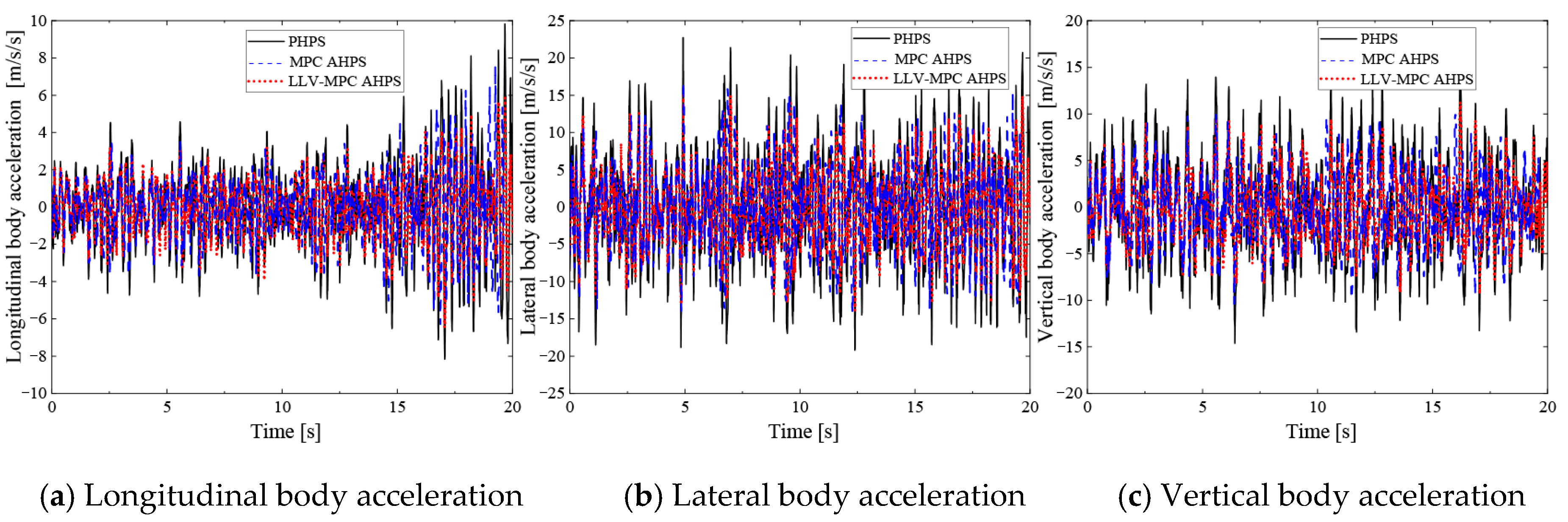
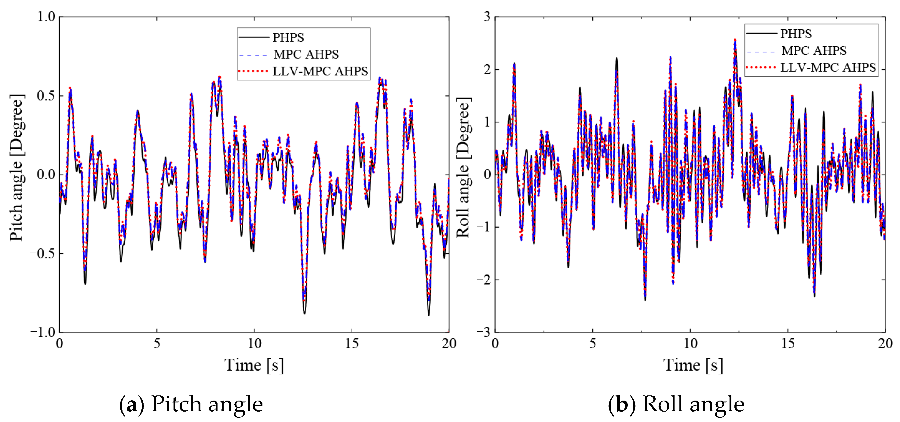
Figure 4, the longitudinal, lateral, vertical, and vertical body acceleration, pitch angle, and roll angle are all improved under the LLV-MPC AHPS and MPC AHPS compared to the PHPS, which improves the ride comfort of the vehicle to a certain extent, but less than 10%. In
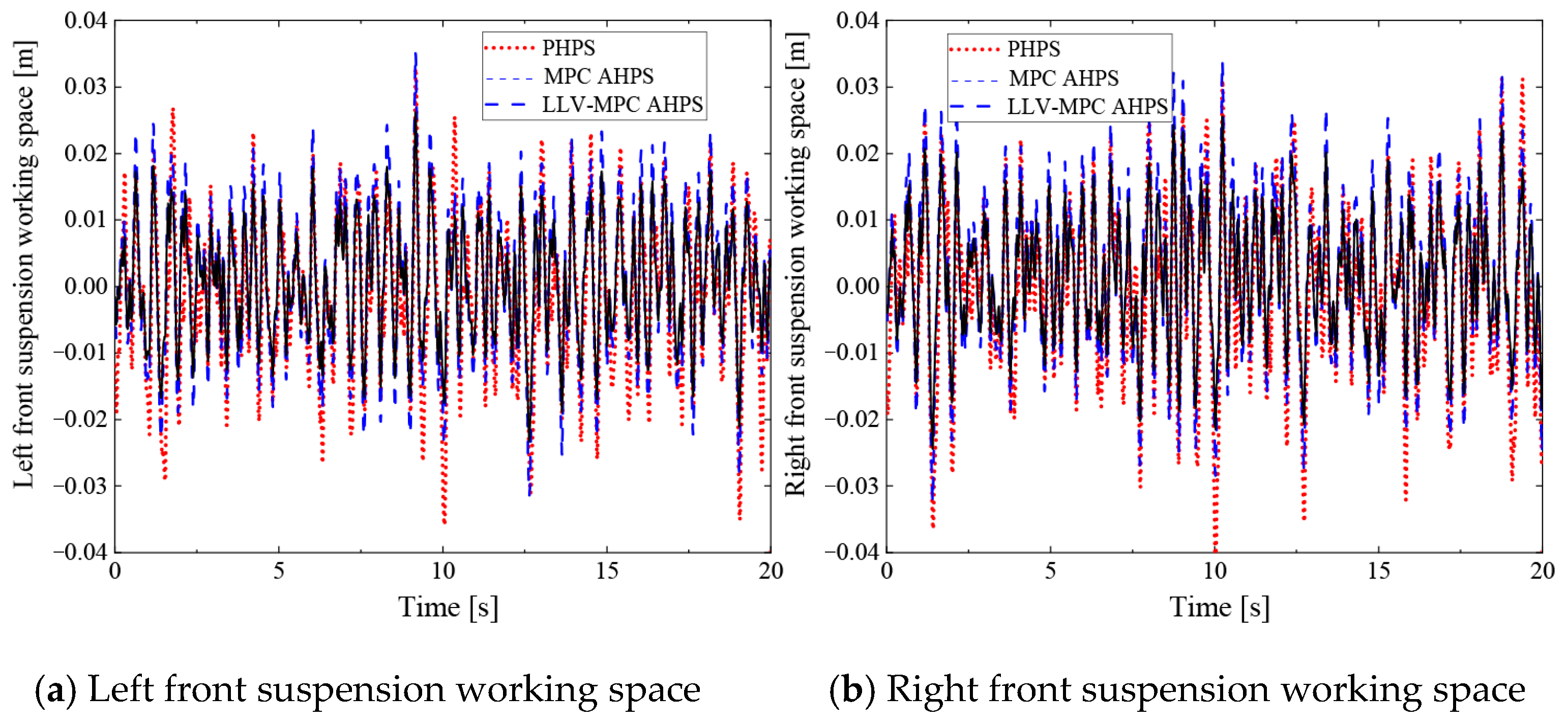
Figure 5, the active hydro-pneumatic suspension RMS of front suspension working spaces increased by 41.9% and 37.1% relative to the passive one during the whole driving process. Although the suspension working space for the truck’s six wheels has increased (
Table 2), it has remained within the working travel range. From
Figure 6 and
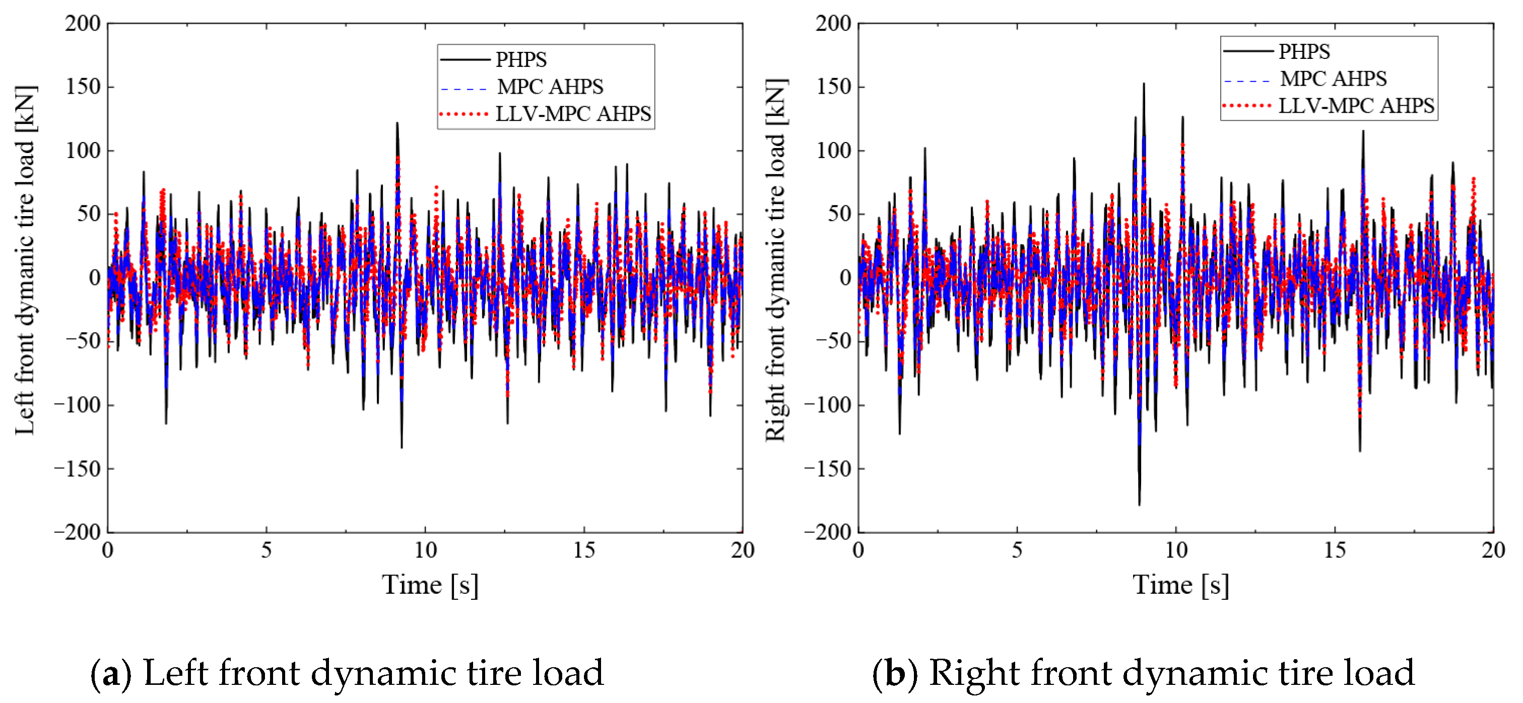
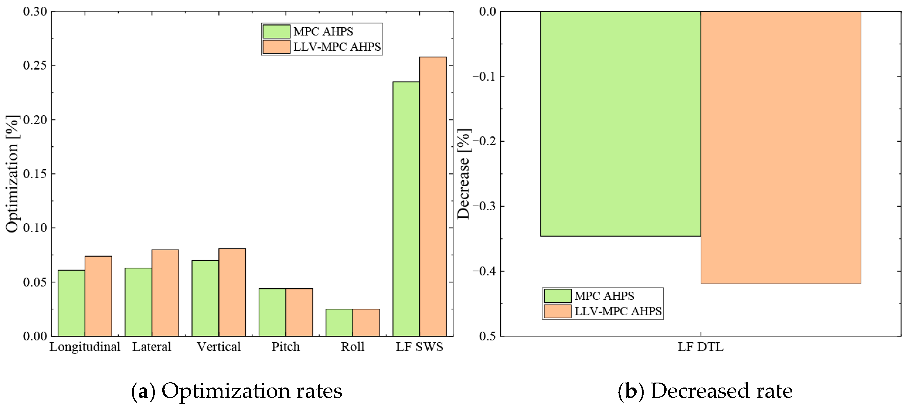
Table 2, it can be seen that the LLV-MPC AHPS reduces the tire dynamic load by 25.8%, 29.1%, 30.6%, 27.6%, 29.9%, and 28.1%, respectively, under C-class road, which improves the grounding of the six wheels to maintain the C-class road surface, reduces the damage to the C-class road surface in the mining area to improve the working environment and increase the operating time. The optimization effect of various indicators for LLV-MPC AHPS is better than that of traditional MPC AHPS in
Figure 7.
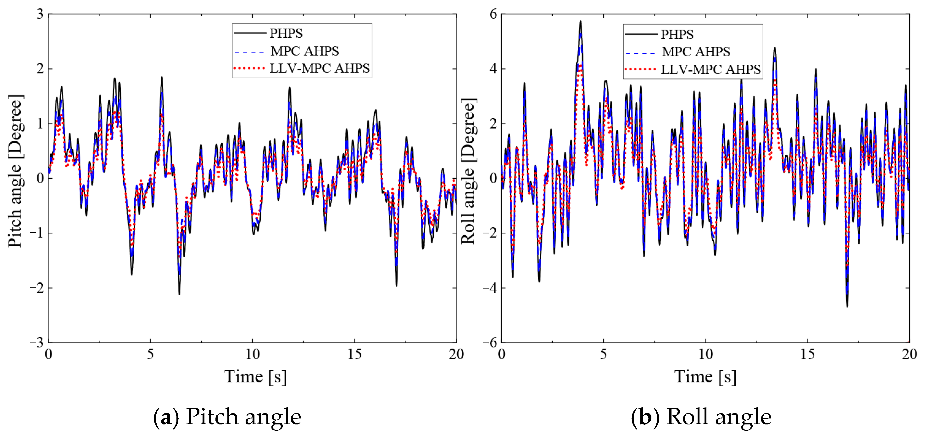
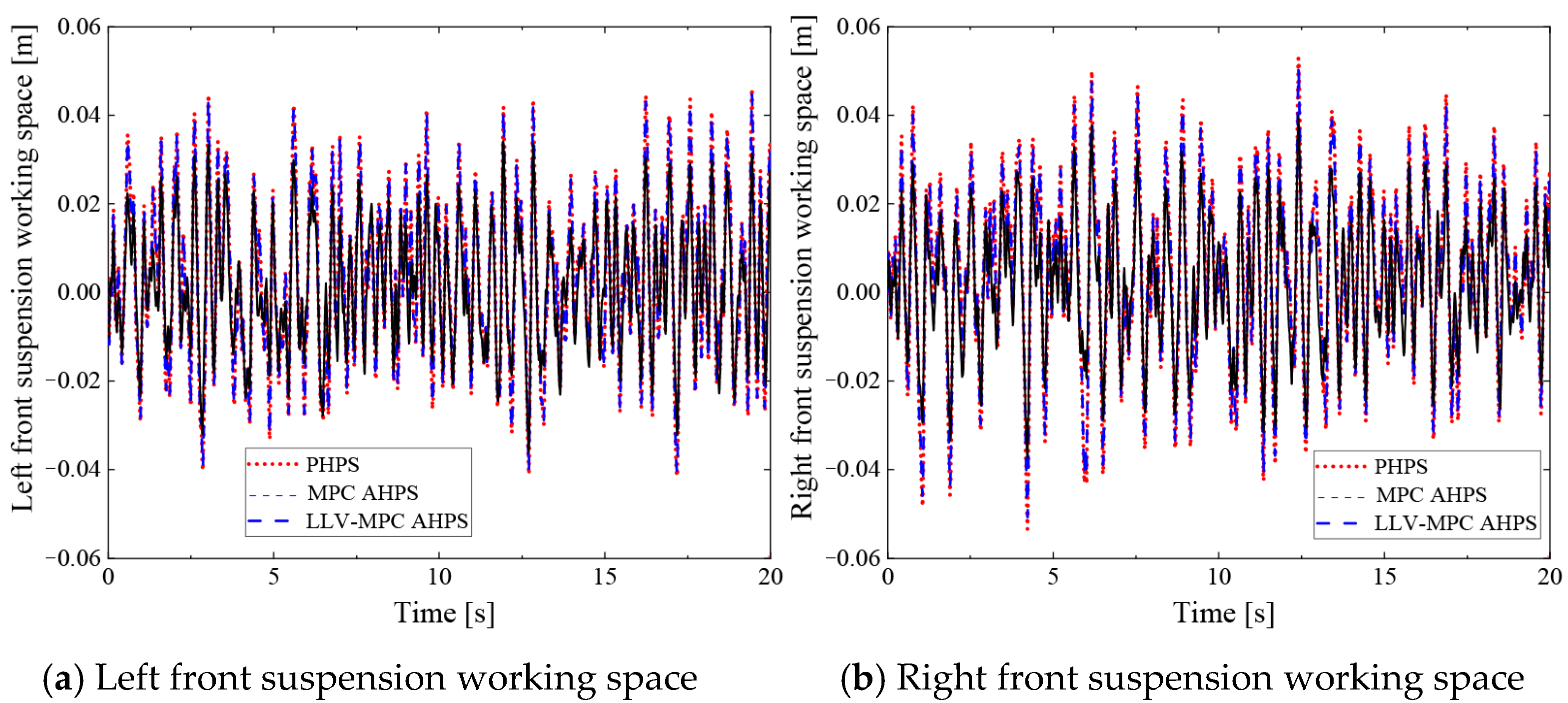
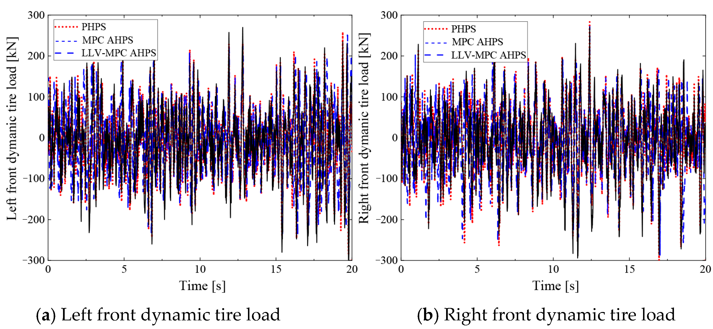
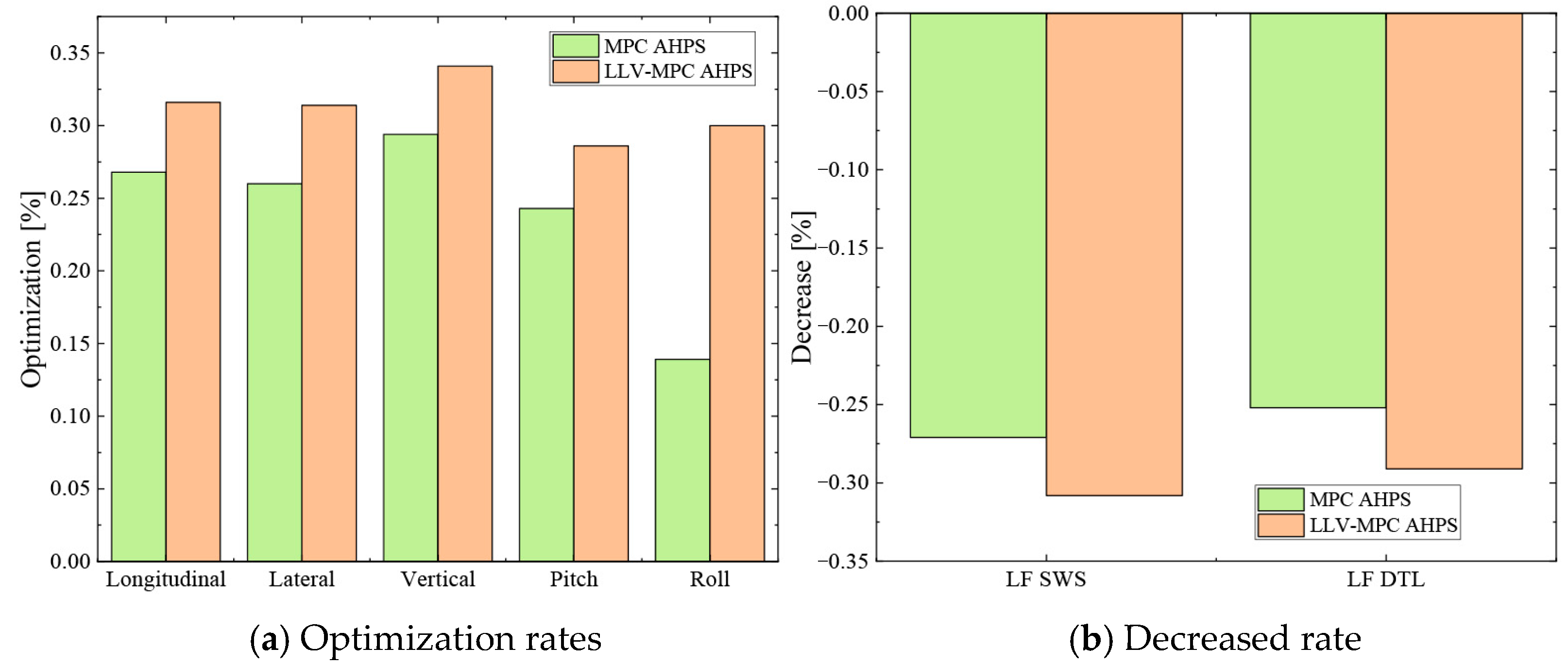
Since E-Class road is the worst road grade among mining roads, the working speed on this road is kept at 27 km/h in unloaded conditions. The control objective under the E-class road is to improve truck comfort as much as possible. The simulation results of the truck dynamic performance under E-class road are given in
Figure 8,
Figure 9,
Figure 10,
Figure 11 and
Figure 12.
As shown in
Figure 8 and
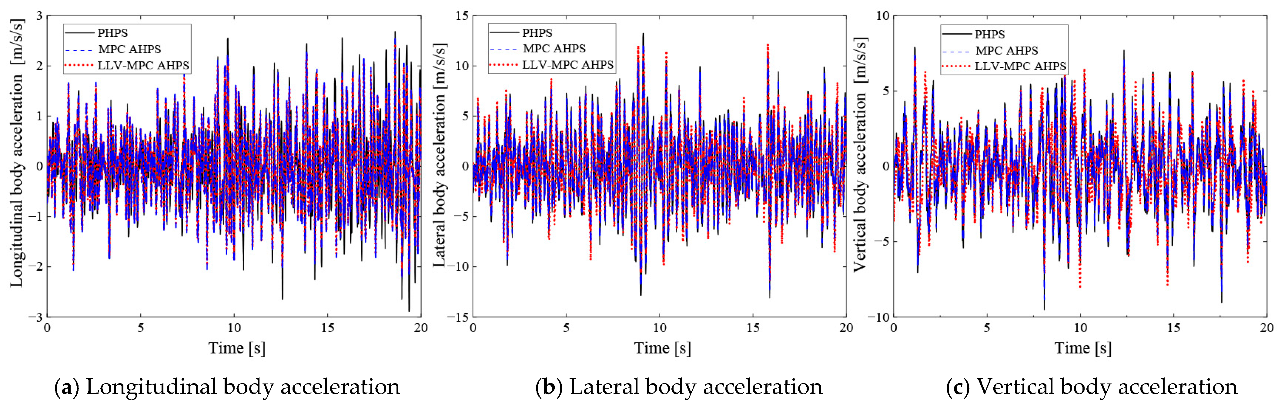
Figure 9, the longitudinal, lateral, and vertical body acceleration of the MPC AHPS and LLV-MPC AHPS are significantly lower than that of the passive hydro-pneumatic suspension; the pitch angle and side inclination angle are optimized to a certain extent compared to the passive suspension. While
Figure 10 corresponds to the deterioration of the suspension working space, the dynamic tire load values of the left and right wheels of the front body in
Figure 11 are locally smaller and locally larger than the corresponding dynamic load values of the wheels of the passive hydro-pneumatic suspension, and in order to be more explicit about the deterioration, the root mean square values of the various performance indexes are shown in
Table 3. It can be clearly seen that under E-class road, the MPC-based active hydro-pneumatic suspension longitudinal, lateral, and vertical coordinated control optimizes the lateral, longitudinal, and vertical body acceleration by 31.6%, 31.4%, and 34.1% and the pitch angle and side inclination angle by 28.6% and 30%, respectively, whereas the root mean square value of the wheel dynamic loads deteriorates by 29.1%, 28.8%, 17.5%, 14.9%, 24.7%, and 31.6%, respectively. From the above analysis, it can be seen that the MPC-based active hydro-pneumatic suspension longitudinal, lateral, and vertical coordinated control strategy under E-class road resulted in a significant improvement in vehicle comfort, based on ensuring that the wheel dynamic loads and suspension working space are within a reasonable range. The optimization effect of various indicators for LLV-MPC AHPS is better than that of traditional MPC AHPS in
Figure 12.