Article

Lubrication Mechanism and Establishment of a Three-Phase Lubrication Model for SCCO2-MQL Ultrasonic Vibration Milling of SiCp/Al Composites

School of Mechanical Engineering, Harbin University of Science and Technology, Harbin 150080, China
*
Author to whom correspondence should be addressed.
Machines 2025, 13(9), 879; https://doi.org/10.3390/machines13090879
Submission received: 26 August 2025 / Revised: 16 September 2025 / Accepted: 20 September 2025 / Published: 22 September 2025
(This article belongs to the Special Issue Machine Tools for Precision Machining: Design, Control and Prospects)

Abstract

SiCp/Al composites (Silicon Carbide Particle-Reinforced Aluminum Matrix Composites), due to their light weight, high strength, and superior wear resistance, are extensively utilized in aerospace and other sectors; nonetheless, they are susceptible to tool wear and surface imperfections during machining, which negatively impact overall machining performance. Supercritical carbon dioxide minimal quantity lubrication (SCCO2-MQL) is an environmentally friendly and efficient lubrication method that significantly improves interfacial lubricity and thermal stability. Nonetheless, current lubrication models are predominantly constrained to gas–liquid two-phase scenarios, hindering the characterization of the three-phase lubrication mechanism influenced by the combined impacts of SCCO2 phase transition and ultrasonic vibration. This study formulates a lubricant film thickness model that incorporates droplet atomization, capillary permeation, shear spreading, and three-phase modulation while introducing a pseudophase enhancement factor βps(p,T) to characterize the phase fluctuation effect of CO2 in the critical region. Simulation analysis indicates that, with an ultrasonic vibration factor Af = 1200 μm·kHz, a lubricant flow rate Qf = 16 mL/h, and a pressure gradient Δptot = 6.0 × 10⁵ Pa/m, the lubricant film thickness attains its optimal value, with Δptot having the most pronounced effect on the film thickness (normalized sensitivity S = 0.488). The model results align with the experimental trends, validating its accuracy and further elucidating the nonlinear regulation of the film-forming process by various parameters within the three-phase synergistic lubrication mechanism. This research offers theoretical backing for the enhancement of performance and the expansion of modeling in SCCO2-MQL lubrication systems.

1. Introduction

With the development of the green manufacturing concept, green and efficient cutting fluids have become a research focus. SCCO2-MQL, as an environmentally friendly lubrication method, shows great potential in the field of difficult-to-machine materials. SCCO2 possesses characteristics such as low viscosity and high diffusivity, and in the supercritical state, it can effectively reduce cutting temperature while decreasing friction and wear [1]. Moreover, minimum quantity lubrication (MQL) atomizes a small amount of cutting fluid with high-pressure gas to form a lubricating oil film at the interface, effectively reducing heat accumulation and lubricant consumption [2]. Therefore, the combination of SCCO2 and MQL can further enhance cooling and lubrication performance and is particularly suitable for composites such as SiCp/Al with significant differences in thermal properties. Furthermore, ultrasonic vibration-assisted milling, as an advanced cutting technology, applies high-frequency vibration to the tool or workpiece, which can reduce cutting force and temperature, improve chip breaking and surface quality, and mitigate tool wear [3]. The synergistic application of ultrasonic vibration with SCCO2-MQL can enhance lubricant film permeability and chip control capability, improve machining stability and quality, and thus hold high engineering application value. Specifically, SCCO2-MQL refers to the use of supercritical carbon dioxide as a carrier medium to deliver a small amount of lubricating oil droplets in the form of a gas–liquid aerosol jet, providing simultaneous cooling and lubrication in the cutting zone. Under the present operating conditions, CO2 remains in a supercritical state, offering high diffusivity to transport droplets efficiently, while its expansion effect at the nozzle outlet contributes to significant temperature reduction. The dispersed oil droplets spread over the tool–workpiece interface to form a thin lubricating film that reduces friction and adhesion. When combined with ultrasonic vibration, the high-frequency oscillation promotes secondary droplet breakup and enhances penetration and film uniformity, further improving the effectiveness of lubrication and cooling.
In recent years, researchers both domestically and internationally have conducted extensive studies on the application of SCCO2-MQL technology in the field of metal machining, verifying its outstanding advantages in cooling and lubrication [4]. The specific research has mainly focused on process performance verification, modeling of lubrication and heat transfer behavior, and multiphase flow property simulation. Multiple experimental studies have shown that SCCO2-MQL technology performs excellently in cutting temperature control, friction reduction, and tool life extension. Nikolaos et al. [5] found in Ti-6Al-4V milling experiments that under SCCO2-MQL conditions, the tool life was 2.6 times longer than with conventional emulsion cooling and eight times that with SCCO2 alone; Wika et al. [6] further pointed out that this technology can effectively extend tool life and reduce the cutting force coefficient. Liu et al. [7] indicated that SCCO2-MQL technology has a significant effect on improving the machining performance of aluminum matrix composites, particularly in suppressing temperature rise and particle damage. Rahim et al. [8], from the perspective of green manufacturing, affirmed the application potential of SCCO2-MQL in balancing environmental protection and performance. In the machining of SiCp/Al composites, Yu et al. [9] verified that SCCO2-MQL technology can significantly reduce surface roughness and subsurface damage. Laghari et al. [10] demonstrated that SiC particles in the machining of SiCp/Al composites cause severe adhesion and abrasive wear, while MQL lubrication can significantly reduce cutting force and tool wear. Regarding the heat transfer behavior and film-forming mechanism in the lubrication process, He et al. [11] proposed a transient thermal analysis model, revealing the dynamic influence of cutting geometry parameters on temperature distribution. Williams and Tabor [12] confirmed that the capillary structure in the tool–chip contact zone plays a significant role in lubricant adsorption; Shi et al. [13] established a capillary permeation model under SCCO2-MQL, elucidating the enhancement mechanism of atomization on lubrication capacity. Pei [14] systematically analyzed the physical basis of minimum quantity lubrication from the perspectives of spray path and wetting diffusion. In terms of modeling methods, Banerjee and Abhay [15] proposed a multi-variable-driven friction model and successfully applied it to finite element simulation. Ji et al. [16] developed an MQL residual stress prediction model based on thermo-elasto-plastic theory, promoting the extension of lubrication behavior simulation to the level of physical constitutive modeling. On the other hand, numerous studies have focused on multiphase state modeling and property variation of SCCO2. Jin et al. [17] revealed, through molecular dynamics, the pseudo-phase structure and density stratification behavior of SCCO2 at the interface. Dousti [18] constructed a compressible Reynolds equation suitable for high-speed lubrication scenarios to simulate the flow state of SCCO2 in bearings. Wahap et al. [19] compared the performance of the Mixture and EMVOF (Eulerian-Multiphase Volume of Fluid) models through CFD (Computational Fluid Dynamics), verifying the flow characteristics of SCCO2 when coupled with solid particles. Tu et al. [20] introduced a liquid-phase permeation model in CGI (Compacted Graphite Iron) cast iron machining, which, although not covering the three-phase process, already considered the coupling between droplets and the thermal boundary layer. In addition, lubrication studies combined with ultrasonic-assisted technology are continuously expanding. Zhang et al. [21] developed an ultrasonic spraying system that significantly reduced droplet size and improved its distribution uniformity. Niu et al. [22] proposed that ultrasonic intermittent cutting can form micro-textured structures on the workpiece surface, effectively enhancing lubricant distribution and heat dissipation capacity. The studies of Verma et al. [23] and Alemayehu et al. [24] further demonstrated that ultrasonic vibration not only improves wettability but also significantly reduces cutting force and surface roughness in difficult-to-machine materials.
In summary, existing studies are mostly limited to gas–liquid two-phase lubrication models and empirical fitting, making it difficult to systematically reveal the coupled effects of CO2 phase transition modulation, lubricant interfacial permeation, and acoustic field disturbances. To address this gap, this work proposes a lubrication film thickness model that integrates atomization kinetics, capillary permeation, shear spreading, and three-phase modulation, and introduces a pseudo-phase enhancement factor βps(p,T) to characterize density fluctuations and phase stratification of supercritical CO2 near the critical region. Within the defined process window, parameter samples are generated using Latin hypercube sampling, and the model coefficients are calibrated through nonlinear regression, resulting in a film thickness prediction equation suitable for SCCO2-MQL ultrasonic vibration milling conditions. Furthermore, a parameter sensitivity analysis is conducted to provide theoretical support for process parameter optimization and the improvement of lubrication performance.

2. Lubrication Mechanism of SCCO2-MQL

In SCCO2-MQL lubrication, CO2 is maintained in the supercritical state under high pressure and moderate temperature, combining the high solubility of a liquid with the high diffusivity of a gas. The high-speed jet at the nozzle outlet atomizes the small quantity of lubricant into fine droplets and delivers them into the cutting zone. The adiabatic expansion of CO2 produces a strong cooling effect, helping to suppress temperature rise at the tool–chip interface. The oil droplets spread across the contact surface to form a lubricating film that reduces friction and adhesion. When ultrasonic vibration is superimposed, it induces secondary breakup of droplets, enhances capillary penetration and shear spreading, and improves the uniformity and stability of the film.
The detailed flow distribution and interaction with the cutting zone are illustrated and explained in the following paragraph and Figure 1.
In SCCO2-MQL ultrasonic vibration-assisted cutting, the mixed mist consists of supercritical CO2, fine lubricating oil droplets, and oil mist steam. The high-pressure CO2 expands and cools at the nozzle outlet but remains in the supercritical state under the given process conditions, without forming cold CO2 or dry ice. Under the combined action of the carrier airflow and ultrasonic vibration, the oil mist is further broken into micron-scale droplets, forming a highly dispersed gas–liquid mixture. As shown in Figure 1, droplets and CO2 enter the cutting area through multiple paths: along the rake face (Direction A), flank face (Direction B), from the side entry (Direction C), and directly into the primary shear zone (Direction D). These multiphase flows reach the first, second, and third deformation zones (I–III), where the coupling of three-phase flow and ultrasonic vibration promotes droplet penetration, enhances lubricant film uniformity, and improves cooling efficiency. This synergistic action effectively reduces cutting force and interfacial temperature, improving machining stability.

2.1. Liquid Atomization Mechanism

In machining under SCCO2-MQL conditions, the lubricant needs to be fully distributed in the form of micron-sized droplets in the tool–workpiece contact area to form an effective lubricating film. The droplet size, atomization position, and jet stability are closely related, and the atomization mechanism constitutes the initial stage of the three-phase lubrication model.
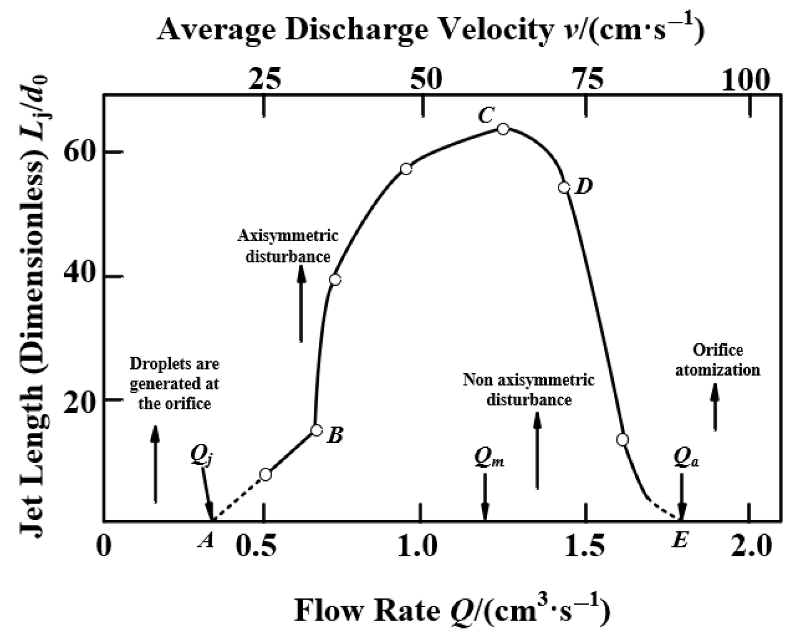
The liquid jet exhibits multi-stage evolution behavior under different flow rate conditions. Figure 2 shows the trend curve of jet stability with the variation in flow rate Q [25]. At point A, corresponding to the subcritical flow rate Qj, the liquid cannot form a jet and only drips at the orifice, with the droplet size controlled jointly by surface tension and gravity. As the flow rate increases to the B–C range, the liquid column becomes stably extended, with its length growing approximately linearly, and the jet exhibits good symmetry. At point C, corresponding to the upper critical flow rate Qm, once this point is exceeded, axial disturbances intensify, the jet structure becomes unstable, and its length decreases rather than increases. When the flow rate reaches point E (Qa), the liquid column rapidly breaks up near the orifice, completing the atomization process, with the continuous length approaching zero. In this process, the breakup mechanism of the jet can be attributed to the nonlinear enhancement of surface disturbances. As shown in Figure 3, the surface of the liquid column is driven by periodic disturbances, forming a wavy necking structure. As shown in Figure 4, when the disturbance amplitude continues to increase, the local surface tension cannot maintain the original shape, and the liquid column undergoes radial contraction and finally breaks at the minimum radius, generating droplets and achieving atomization.
The average diameter de (µm) of atomized droplets is an important parameter for describing the atomization effect. The droplet size is influenced by the nozzle diameter dn (µm), disturbance frequency, and liquid properties, and satisfies the following relationship:
d e = 0.9 d n λ / d n 1 3
In Equation (1), λ is the wavelength of the surface disturbance of the jet (µm), expressed as λ = π d n ρ / γ . Ultrasonic vibration indirectly modulates λ by changing the fluid velocity v (m/s). When the vibration frequency f (kHz) approaches the natural frequency of the jet f n = γ / ρ d n 3 , λ is significantly reduced.
In characterizing the droplet breakup capability, the fluid velocity fluctuations induced by ultrasonic vibration are taken into account, and the dimensionless Weber number (We) is accordingly modified:
W e = ρ v + A ω cos 2 π f t 2 d e γ
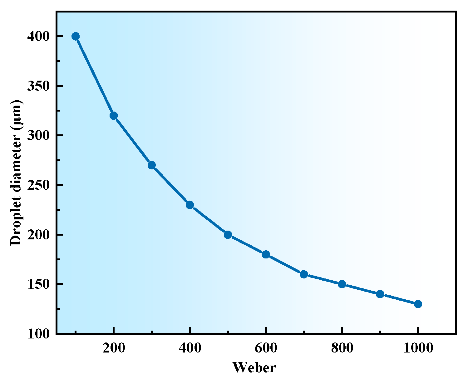
In Equation (2), ρ denotes the liquid density (kg/m3), v is the initial droplet velocity (m/s), de represents the droplet diameter (μm), γ is the liquid surface tension (N/m), A is the ultrasonic amplitude (μm), and ω = 2πf is the vibration angular frequency (rad/ms). As illustrated in Figure 5, a larger Weber number (We) corresponds to a smaller droplet size, indicating that higher flow velocity or lower surface tension facilitates the formation of finer droplets.
The smaller the droplet size, the easier it is to penetrate into the micro-gaps between the tool and the workpiece and to spread rapidly, which facilitates the establishment of a stable lubricating film. The atomization stage not only determines the initial distribution state of the lubricant but also provides the physical basis for subsequent capillary infiltration and hydrodynamic film formation.

2.2. Capillary Infiltration Dynamics

After droplet atomization, the lubricant enters the tool–workpiece contact region, but whether it can truly penetrate the interfacial microstructure still depends on its capillary wetting and percolation capacity with respect to the surface morphology. Capillary action is the dominant mechanism by which the lubricant penetrates microcracks, pits, or grooves, serving as the critical intermediate step in the transition from droplet distribution to the formation of a continuous lubricating film. As shown in Figure 6, a narrow interfacial channel is formed between the tool and the workpiece, containing a gas phase region and a high-temperature vacuum zone, with scrap chips accumulated nearby. Cutting fluid enters this region from the outside, and the lubricant is driven forward through the gas phase and drawn into the channel under the combined action of capillary suction and liquid–solid interfacial adhesion. The equivalent channel diameter 2 r and the length l determine the penetration resistance and the depth that the lubricant can reach; the coordinate y represents the distribution of pressure and velocity along the channel; and u denotes the average penetration velocity. Within this mechanistic framework, different lubrication conditions affect the capillary driving force and the efficiency of film formation. Under SCCO2-MQL conditions, the droplet size is smaller, and the wettability is enhanced, leading to a greater capillary driving force and deeper penetration paths. As a result, the lubricant can rapidly cover the bottom of the contact interface, spread to form a continuous film, significantly reduce friction and interfacial temperature, and promote the establishment of a stable lubrication layer.
The capillary rise phenomenon formed by the lubricant in capillary tubes can be described using a static capillary model. However, during the actual cutting process, the lubricant is in a non-steady dynamic penetration stage, where the effects of time and ultrasonic vibration need to be considered. Therefore, the Lucas–Washburn model is introduced and modified accordingly, as shown in Equation (3).
h ( t ) = γ cos θ t μ 1 + A f v c
In Equation (3), h(t) is the dynamic penetration height (μm), γ is the liquid surface tension (N/m), θ is the contact angle (°), μ is the dynamic viscosity of the lubricant (Pa·s), v c = γ / ρ · r is the capillary characteristic velocity (μm/ms), A is the ultrasonic amplitude (μm), and f is the ultrasonic vibration frequency (kHz).
The capillary effect plays a crucial driving role in the penetration of lubricant into the micro-channels between the tool and the workpiece, and the penetration rate and depth are significantly enhanced under the synergistic action of ultrasonic vibration and droplet atomization.

2.3. Boundary Layer Theory

After penetrating into the micro-channel structure between the tool and the workpiece through capillary action, the lubricant is influenced by the relative interfacial motion, leading to the formation of a pronounced shear velocity distribution inside the channel. Typically, the velocity of the lubricant approaches zero near the solid wall and exhibits a distinct gradient along the channel thickness direction. Such flow characteristics can be regarded as a typical laminar boundary-layer behavior.
In such a boundary layer, the lubricant is subjected to shear forces that drive its further extension along the channel, thereby enabling the spreading and stretching of the lubricating film on the micro-interface. The boundary-layer thickness δ and the channel flow velocity u are the primary factors determining the spreading capability of the lubricant, and the velocity distribution can be approximately expressed as Equation (4):
u ( y ) = 1 2 μ d p d x y ( h y )
In Equation (4), u(y) denotes the lubricant velocity at the normal position y within the channel (μm/s), μ is the dynamic viscosity of the lubricant (Pa·s), dp/dx represents the pressure gradient inside the channel (Pa/m), and h is the channel height (film thickness, μm). This velocity distribution clarifies the role of shear rate in governing the interfacial spreading of the lubricant.
It should be noted that the derivation of Equation (4) is based on the Newtonian fluid assumption, where the dynamic viscosity μ is constant and independent of the shear rate. This assumption is valid for conventional MQL lubricants under moderate shear rates and laminar flow conditions. However, in more complex lubrication scenarios—such as SCCO2-MQL gas–liquid–solid multiphase flow, liquid–metal-based lubricants, or ionic liquids—the fluid often exhibits non-Newtonian rheology, and the presence of dispersed phases (oil droplets, bubbles, or solid particles) significantly alters the velocity distribution and shear stress field within the channel [26]. Therefore, Equation (4) should be generalized to non-Newtonian and multiphase systems to more realistically characterize the spreading behavior of the lubricant film under shear [27].
For non-Newtonian fluids, the viscosity can be expressed as a function of the shear rate, μe(γ), whose commonly used forms are:
μ e ( γ ) = K γ n 1 , Power-law   model μ + ( μ 0 μ ) 1 + ( λ γ ) a n 1 a , Carreau--Yasuda   model
In Equation (5), γ ≈ ∣∂u/∂y∣ is the local shear rate (s−1); K is the consistency index (Pa·sn); n is the flow index (n < 1 for shear-thinning, n > 1 for shear-thickening fluids); μ0 and μ are the zero- and infinite-shear viscosities (Pa·s); λ is a characteristic time constant (s); and a is a dimensionless shape parameter. Substituting μe(γ) into Equation (4) and iteratively solving the velocity field yields a distribution consistent with the nonlinear rheology of the lubricant.
When the lubricant is a gas–liquid–solid mixture, the fluid properties should be expressed as effective values by volume-fraction weighting:
ρ e = ( 1 ϕ d ) ρ c + ϕ d ρ d , μ e = μ c 1 + 2.5 ϕ d , Einstein   approximation μ c 1 ϕ d ϕ m η ϕ m , Krieger-Dougherty   relation
In Equation (6), subscripts c and d denote the continuous and dispersed phases, respectively; ϕd is the dispersed phase volume fraction (dimensionless); ϕm is the maximum packing fraction; and η is the intrinsic viscosity (typically η ≈ 2.5 for rigid spheres). These effective properties enable the calculation of velocity profiles and shear rate distributions that account for concentration effects and interfacial interactions, thus better representing the lubrication behavior in practical machining environments.
This generalization not only broadens the applicability of the model to various lubricants but also provides a theoretical basis for investigating novel lubrication systems such as liquid metals and ionic liquids, ultimately enhancing the predictive capability and physical interpretability of the model for complex multiphase lubrication scenarios.
Moreover, under SCCO2-MQL conditions, ultrasonic vibration periodically disturbs the boundary layer structure, enhancing velocity fluctuations within the channel and indirectly improving the shear-induced spreading capability of the lubricant. This vibration-induced variation in sliding rate is represented in the modeling through the Masjedi–Khonsari model, in which the total film thickness h can be expressed as Equation (7):
h = K U μ W 0.6 1 + α A f U
In Equation (7), K denotes the material constant, with K = 1.2 for SiCp/Al (dimensionless); U represents the velocity parameter (m/s); W is the normal load (N); S denotes the sliding rate (dimensionless); α is the vibration sensitivity coefficient (dimensionless); and Af represents the vibration factor (μm·kHz).
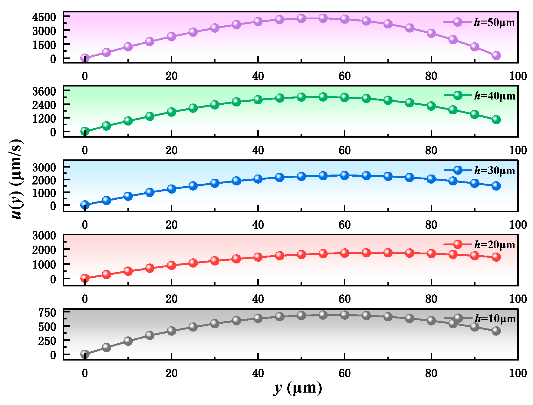
After entering the micro-channel, the lubricant develops a distinct shear velocity distribution between the channel walls. This distribution exhibits a parabolic profile, with the maximum velocity at the center and zero velocity at the wall surfaces. The variation trend is closely related to the channel height. Therefore, numerical calculations were performed in this study under the conditions of channel height h = 10~50 μm and normal position y = 0~100 μm. The results are shown in Figure 7.
As shown in Figure 7, with the increase in channel height h, the peak of the velocity distribution curve rises significantly, and the velocity gradient in the boundary layer becomes steeper. This indicates that the driving effect of shear stress on the spreading behavior of the lubricant is enhanced, which facilitates the formation of a wider lubricant film coverage.

2.4. Hydrodynamics

The macroscopic flow behavior of the disturbed lubricant at the cutting interface is modeled by analyzing the velocity and pressure evolution from the perspective of fluid mechanics. The lubricant in the microchannel can be regarded as an incompressible Newtonian fluid, and its governing equation is the Navier–Stokes equation:
ρ v t + v v = p + μ 2 v + F ext
In Equation (8), ρ denotes the lubricant density (kg/m3), μ is the dynamic viscosity (Pa·s), v represents the velocity vector field (m/s), ∇p denotes the pressure gradient (Pa/m), and Fext is the external force source (N).
To describe the ultrasonic influence under SCCO2-MQL, the external disturbance term is expressed as a periodic force, as shown in Equation (9).
F ext = ρ A ω 2 sin ( ω t ) n
In Equation (9), A denotes the ultrasonic amplitude (μm), ω is the vibration angular frequency (rad/s), t represents time (s), and n is the unit vector along the vibration direction.
Within the near-wall region of the boundary layer, the velocity distribution is approximated by a linear profile, as expressed in Equation (10).
v ( y ) = v ( t ) max 1 y δ
In Equation (10), v(y) represents the velocity at any height y within the boundary layer (m/s), and δ denotes the boundary layer thickness (μm). The periodic variation of vmax(t) modulates the velocity field v(y), pressure gradient ∇p, and shear stress, highlighting the dynamic influence of ultrasonic excitation.
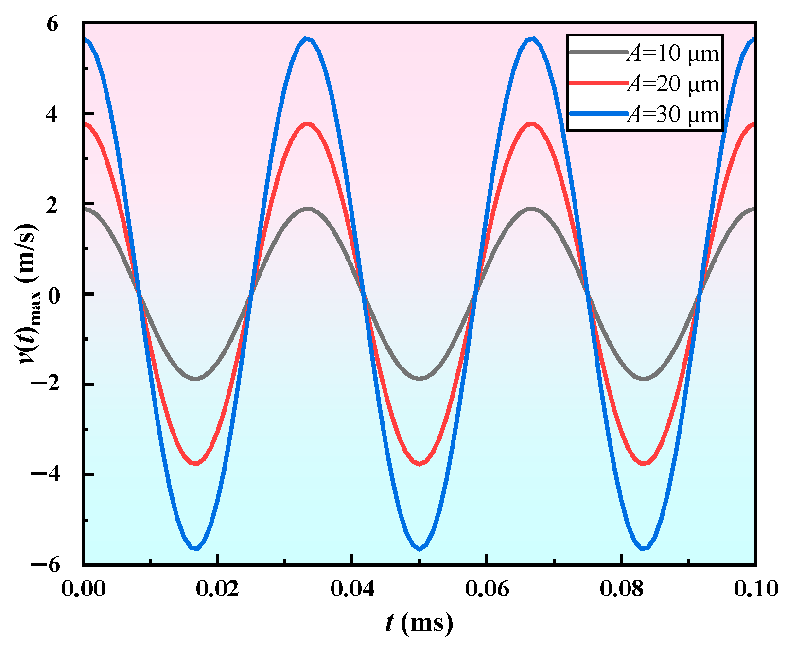
To further characterize the modulation effect of vibration disturbance on lubricant velocity, the temporal evolution of the central velocity was extracted based on the velocity model vmax(t) = cos(ωt). With the vibration frequency set at 30 kHz and the angular frequency defined as ω = 2πf, calculations were conducted under amplitudes of A = 10, 20, and 30 μm, as illustrated in Figure 8.
As shown in Figure 8, the fluctuation amplitude of the lubricant central velocity v(t) increases significantly with the rise of vibration amplitude A. All three curves exhibit sinusoidal profiles with identical phase, indicating good periodic stability and synchronization of the vibration disturbance. At a frequency of f = 30 kHz, increasing the amplitude from 10 μm to 30 μm raises the velocity fluctuation peak from approximately ±1.88 m/s to ±5.65 m/s, showing a linear growth trend. The velocity disturbance directly influences the shear rate and pressure gradient distribution of the lubricant in the microchannel, thereby enhancing the spreading ability and dynamic stability of the lubrication film. These findings suggest that, under SCCO2-MQL conditions, ultrasonic vibration regulates the velocity distribution of the lubricant and markedly improves both film-forming conditions and interfacial response characteristics.

3. Modeling and Simulation of Three-Phase Lubrication Mechanism in SCCO2-MQL

3.1. Mathematical Modeling of Lubrication Film Thickness

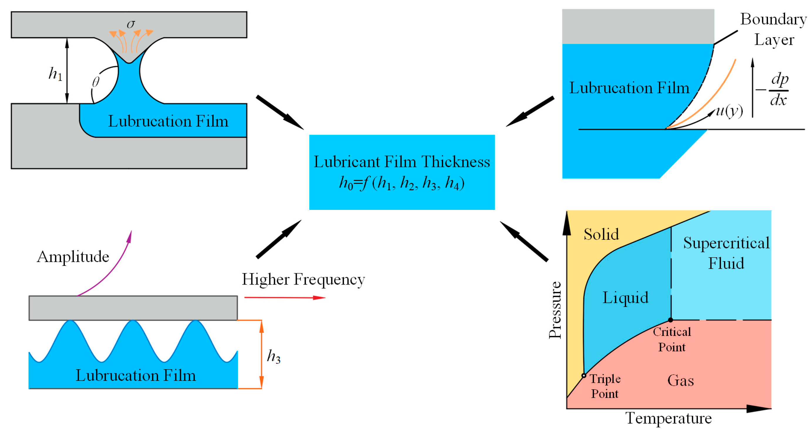
The lubrication performance in the SCCO2-MQL ultrasonic vibration milling process is primarily reflected in the formation and stability of the lubrication film at the cutting interface. The film thickness is influenced by multiple factors, including the initial penetration of the lubricant, boundary layer shear, ultrasonic disturbance, and the three-phase state of CO2. To systematically characterize its evolutionary process, a coupled multiphysics mathematical model was established, as illustrated in Figure 9.
At the nozzle outlet, CO2 may exhibit a proportional distribution of gas, liquid, and solid phases under the influence of pressure and temperature, while its density and viscosity fluctuate significantly with changing operating conditions, thereby affecting the transport behavior of the lubricant within the microchannel. In particular, within the transition zone from supercritical to subcritical states, CO2 often exhibits a pronounced density stratification effect, with the contribution of the liquid phase being further reinforced. Therefore, based on these coupled behaviors, a modulation function is established, as expressed in Equation (11).
f ( h 4 ) = 1 + β p s ( p , T ) + β s Φ s
In Equation (11), βps(p,T) denotes the pseudo-phase enhancement factor; Φs represents the solid-phase volume fraction; and βs is the solid-phase modulation coefficient, reflecting the perturbation capability of solid particles on the film formation behavior.
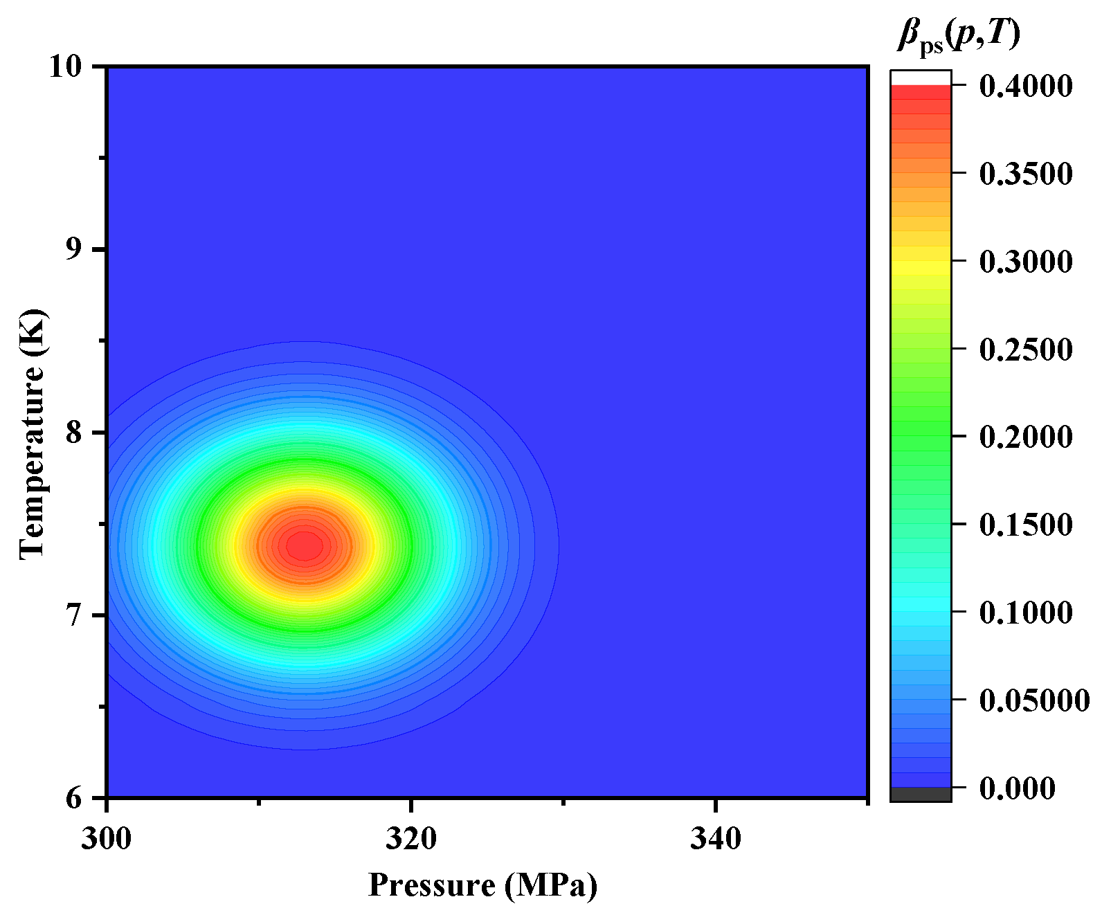
In the CO2 three-phase modulation mechanism, the pseudo-phase enhancement factor βps is one of the core parameters, which reflects the density fluctuations of CO2 in the supercritical region and the associated enhancement of liquid-phase lubrication. Its distribution characteristics under the dual variables of pressure and temperature are illustrated in Figure 10.
Figure 10 shows that the enhancement effect is predominantly concentrated in the vicinity of the critical state (approximately 7.38 MPa, 313 K), exhibiting a typical local amplification characteristic. This finding indicates that, within the supercritical–subcritical transition region, CO2 undergoes density stratification and phase fluctuations, thereby significantly enhancing the liquid-phase contribution to lubrication film formation.
The lubrication film thickness is characterized as a nonlinear outcome of multiple coupled physical mechanisms. Accordingly, the overall film thickness is formulated as Equation (12). In this expression, Af represents the product of amplitude and frequency, introduced as an empirical parameter with the unit μm·kHz. Although it does not possess a rigorous physical dimension, it is adopted herein as an empirical parameter to quantify the modulation intensity of ultrasonic vibration.
h = γ cos θ t μ 1 + α 1 A f 1 + K U μ W 0.6 2 1 + β p s ( p , T ) + β s Φ s 3
In Equation (12), the first term corresponds to the capillary infiltration effect, reflecting the influence of wettability on the initial film-forming capability of the lubricant. The second term represents the shear-spreading contribution, describing the expansion and distribution of the lubricant film induced by interfacial relative motion. The third term denotes the three-phase modulation factor, which quantifies the overall regulation of film formation arising from the complex phase-state distribution of CO2. Consequently, the formation of lubrication film thickness can be regarded as a nonlinear outcome of multi-physical mechanisms coupling. This model not only elucidates the independent contributions of each mechanism to the film formation process but also provides a theoretical foundation for subsequent simulation analysis and experimental validation.

3.2. Model Simulation and Parameter Response Analysis

To quantitatively predict the lubrication film thickness hc (μm), Max et al. [28] proposed a classical elastohydrodynamic lubrication model based on the dimensionless velocity U (dimensionless), material elasticity G (dimensionless), and load parameter W (dimensionless). The central film thickness can be predicted using the empirical formulation expressed in Equation (13). This model has been widely applied under rolling contact conditions, effectively characterizing the nonlinear response relationships among contact geometry and lubrication parameters.
h c C U a G b W c
Building upon this theoretical framework, and considering the multiphase characteristics, shear disturbance, and lubricant supply behavior inherent in SCCO2-MQL ultrasonic vibration-assisted lubrication, the present study introduces additional key parameters—namely, the vibration factor Af (μm·kHz), lubricant flow rate Qf (mL/h), and pressure gradient Δptot (Pa/m). Accordingly, a modified film thickness model suitable for the three-phase cooperative lubrication regime is established, as shown in Equation (14).
h = C Q f b 1 ( A f ) b 2 ( Δ p tot ) b 3
In Equation (14), to explicitly incorporate the configuration effect of the SiCp/Al composite (with a SiC volume fraction of 45%) into the lubrication film formation mechanism, an equivalent modeling approach is developed based on interfacial wettability and capillary driving force. According to stereological principles, the planar area fraction can be approximated by the volume fraction in a statistical sense; considering that particle detachment or coverage may occur during cutting, an exposure correction factor χ ∈ (0,1] is introduced, yielding the surface particle exposure area fraction as ϕp = χ × 0.45. Based on this, the Cassie–Baxter equation is used to determine the effective contact angle of the composite surface, as shown in Equation (15).
cos θ e = ϕ p cos θ Sic + 1 ϕ p cos θ Al
In Equation (15), θe is the effective contact angle (°), θSiC and θAl are the contact angles of the lubricant on SiC and Al surfaces (°), ϕp is the particle exposure area fraction (dimensionless), and χ is the particle exposure correction factor (dimensionless).
From Equation (15), the effective contact angle θe varies monotonically with the surface particle exposure fraction ϕp, thus accurately representing the actual wettability state of the composite surface. As ϕp increases, cosθe also increases, leading to a stronger capillary driving force and facilitating lubricant penetration into the interface. By substituting θe into the capillary pressure term and combining it with the equivalent capillary radius req characterizing the microchannel geometry, the effective pressure gradient Δptot in Equation (16) is obtained. The equivalent radius req can be approximated using the particle equivalent diameter deq, nearest-neighbor spacing s, and substrate surface roughness Ra:
s d e q π 6 ϕ p 1 / 3 1 ,   r eq 1 2 ( s d e q ) + ζ R a
where ζ is a geometric correction factor, to account for the amplification or attenuation effect of surface roughness on the channel size. The parameter deq represents the equivalent diameter of SiC particles (μm), which is statistically obtained from the particle size distribution. Through this approximation, the SiC volume fraction, particle exposure, wettability, and microchannel geometry are consistently mapped into the driving force for lubricant penetration Δptot, which is then used in Equation (14) to determine the film thickness h, thereby quantitatively incorporating the material configuration effect into the model.
The capillary pressure difference is then superimposed with the external pressure gradient to obtain the effective pressure gradient, as expressed in Equation (17).
Δ p tot = Δ p ext + 2 σ cos θ e r eq
In Equation (17), Δptot represents the effective pressure gradient (Pa/m) and serves as the input for Equation (14). Δpext is the externally applied pressure gradient (Pa/m), σ is the lubricant interfacial tension (N/m), and req is the equivalent capillary radius (m), which is determined by the particle size distribution, spacing, and surface roughness geometry.
Through this approach, the composite’s volume fraction, surface particle exposure, contact angle, and microchannel dimensions are transformed into the effective pressure gradient that drives lubricant penetration, thereby embedding the influence of material configuration on film thickness in Equation (14) in a physically interpretable manner. Compared with classical elastohydrodynamic lubrication models that primarily focus on the response of film thickness to load-geometry-viscosity interactions, the proposed model not only incorporates material-interface characteristics but also emphasizes the dynamic modulation of film thickness by shear disturbance and lubricant supply conditions. This makes it particularly suitable for lubrication scenarios involving the coupling of SCCO2-MQL and ultrasonic vibration, enabling the elucidation of the dynamic evolution of the novel film formation mechanism.
To determine the undetermined coefficients C, b1, b2, and b3 in Equation (14), a simulated dataset was constructed to represent the actual operating conditions of SCCO2-MQL. The selection of parameter ranges was comprehensively determined based on practical machining conditions and equipment capabilities. A lubricant flow rate of Qf = 8~16 mL/h corresponds to the typical range used in MQL applications, ensuring stable atomization while avoiding excessive lubricant accumulation and backflow. Ultrasonic amplitude and frequency, A = 10~30 μm and f = 20~40 kHz, cover the principal operating window of ultrasonic systems, providing sufficient shear enhancement without inducing boundary-layer instability. The interfacial pressure gradient Δptot = 1.0 × 10⁵~6.0 × 10⁵ Pa/m reflects the characteristic pressure drop from the nozzle outlet to the cutting zone in SCCO2 delivery, balancing the driving force for lubricant penetration with the need to maintain film stability.
Within this defined parameter space, representative sample points were generated using the Latin hypercube sampling (LHS) method. For each parameter set, the physics-based numerical model—incorporating atomization, capillary infiltration, shear disturbance, and pseudo-phase modulation mechanisms—was solved to compute the steady-state film thickness, yielding a reference dataset that serves as the baseline for regression fitting and accuracy verification. Subsequently, nonlinear least-squares regression of the multiplicative three-variable model was performed in MATLAB 2024a using the fitnlm function, leading to the optimized fitting expression given in Equation (18):
h = 8.95 × 10 5 Q f 0.280 ( A f ) 0.488 ( Δ p tot ) 0.423
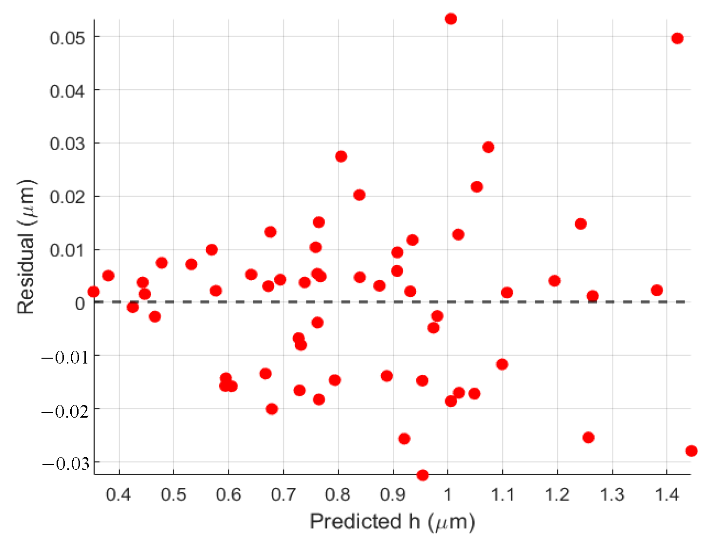
To validate the fitting accuracy of the model in Equation (18), the predicted film thickness values calculated from Equation (18) were compared with the reference values obtained from the numerical simulation dataset, and the residual distribution was analyzed. The results are shown in Figure 11 and Figure 12. In Figure 11, the predicted values exhibit excellent agreement with the reference data, with the scatter points closely distributed around the ideal fitting line, demonstrating the strong predictive capability of the model. Figure 12 illustrates the residuals as a function of the predicted film thickness. The residuals remain within a narrow fluctuation range and follow a random distribution without discernible systematic deviation, confirming that the developed model possesses robust stability and consistency across the entire parameter space.
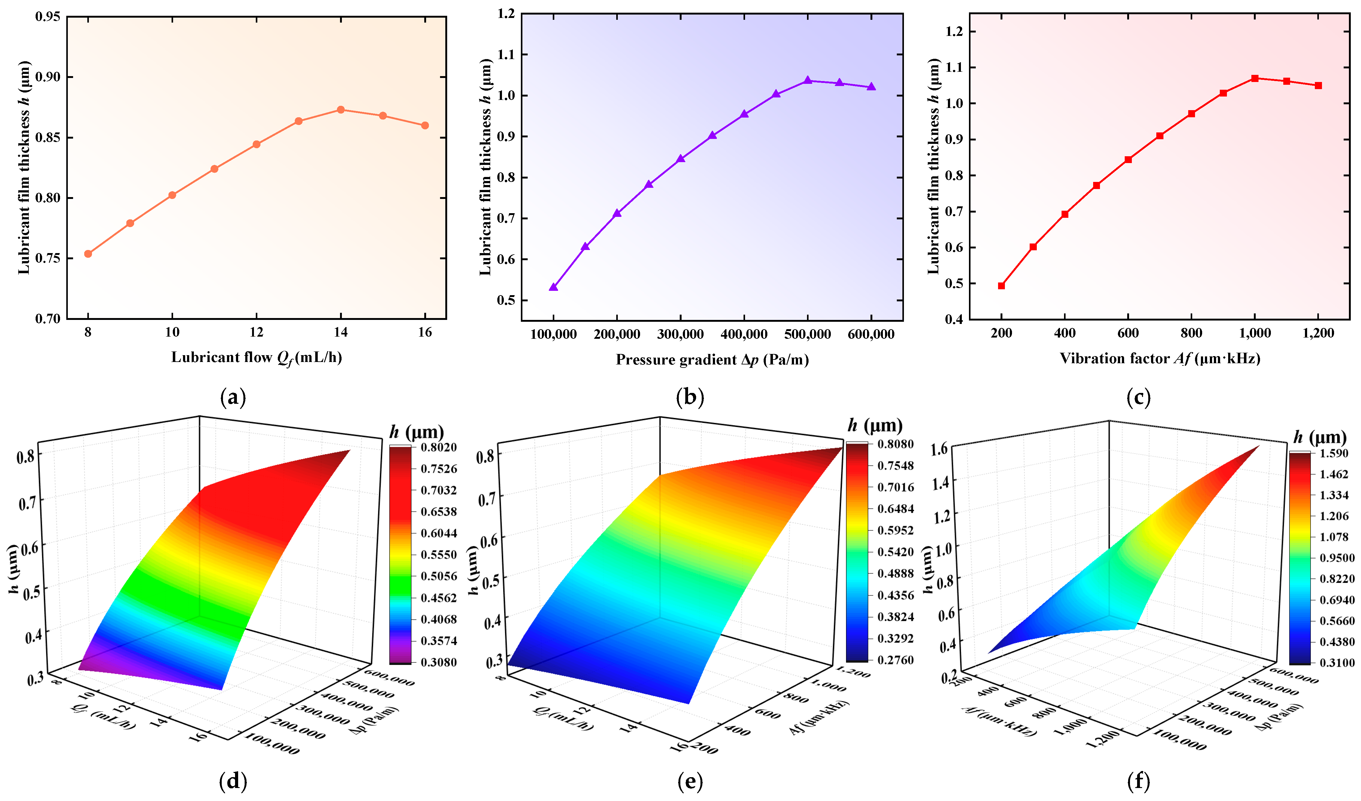
Under the conditions of Qf = 12 mL/h, Af = 250 μm·kHz, and Δptot = 1 × 10⁵ Pa/m, calculations were performed using the fitted model (Equation (18)) to obtain the variation trend of the lubrication film thickness h, as shown in Figure 13.
Figure 13a illustrates the trend of lubrication film thickness h as a function of flow rate Qf under the conditions Af = 250 μm·kHz and Δptot = 1.0 × 10⁵ Pa/m. As Qf increases from 8 mL/h to 14 mL/h, h rises continuously, indicating that sufficient lubricant supply promotes interfacial film formation. When Qf > 14 mL/h, however, h slightly decreases, which may be attributed to lubricant accumulation and enhanced boundary-layer disturbance. These results suggest the existence of an optimal Qf range: insufficient supply hinders film formation, whereas excessive supply leads to instability. Figure 13b presents the variation of h with Δptot. At Qf =12 mL/h and Af = 250 μm·kHz, the film thickness generally increases with Δptot, but tends to saturate or slightly decline when Δptot > 5.0 × 10⁵  Pa/m. This indicates that, although a higher pressure gradient enhances lubricant penetration and film formation, excessively high Δptot may induce interfacial perturbation and film rupture. Thus, the optimal lubrication effect is achieved when Δptot is maintained within 4.5–5.0 × 10⁵ Pa/m. Figure 13c shows the influence of Af on h under Qf = 12 mL/h and Δptot = 4 × 10⁵ Pa/m. As Af increases to approximately 1000 μm·kHz, the film thickness grows rapidly, after which the growth rate slows and even declines, suggesting the presence of a saturation point. Moderate ultrasonic excitation is beneficial for film formation, with an optimal Af range of 800–1000 μm·kHz.
Figure 13d illustrates the synergistic effect of Qf and Δptot on h under the fixed condition Af = 250 μm·kHz. The film thickness increases with the simultaneous rise of both parameters, reaching its peak near Qf = 16 mL/h and Δptot = 6.0 × 10⁵ Pa/m. This result indicates that flow rate provides the lubricant supply, while pressure gradient enhances its penetration, jointly producing a typical synergistic effect. Figure 13e depicts the influence of Af and Qf on h at Δptot = 1.0 × 10⁵ Pa/m. Concurrent increases in Af and Qf markedly enhance film thickness, with hhh attaining a maximum near Af = 1200 μm·kHz and Qf = 16 mL/h. Ultrasonic excitation strengthens shear–induced disturbance, while lubricant supply promotes spreading; their combination drives lubricant redistribution and effectively improves film formation. Figure 13f shows the combined effect of Af and Δptot under Qf = 12 mL/h. The film thickness grows significantly with simultaneous increases of Af and Δptot, achieving its maximum near Af = 1200 μm·kHz and Δptot = 6.0 × 10⁵ Pa/m This suggests that, under low flow-rate conditions, appropriately increasing Af and Δptot can compensate for lubricant deficiency, markedly enhancing the thickness and stability of the lubrication layer.
In summary, under the conditions of Qf = 16 mL/h, Δptot = 6.0 × 10⁵ Pa/m, and Af = 1200 μm·kHz mbination for the SCCO2-MQL lubrication system and providing guidance for practical parameter optimization.
It is noteworthy that SiCp/Al composites, owing to their high hardness, low thermal expansion coefficient, and excellent specific strength, are widely used in aerospace, automotive, and electronic packaging industries as ideal candidates for lightweight and high-performance structural components. However, the presence of the SiC reinforcing phase makes the cutting process highly susceptible to severe tool wear, particle fracture, interfacial delamination, and surface tearing, which lead to large cutting force fluctuations, intense temperature rise, and deterioration of surface quality, thereby challenging machining stability and consistency. These issues place more stringent demands on the film-forming capacity, penetration depth, and heat dissipation efficiency of the lubricant. The combined application of SCCO2-MQL and ultrasonic vibration can form a uniform and stable gas–liquid–solid three-phase lubrication film in the cutting zone, significantly reducing interfacial friction and peak temperature, while the high-frequency shear action promotes secondary droplet breakup and deep penetration along the interface. This effectively mitigates tool wear and improves surface integrity. This study not only elucidates the film formation mechanism of SiCp/Al under such special lubrication conditions but also provides theoretical guidance and engineering references for lubrication control strategies and process parameter optimization of other difficult-to-machine composites.

3.3. Parameter Sensitivity Analysis

To further identify the key controlling factors influencing the lubrication film thickness h and to enhance the engineering adaptability of parameter settings, as well as the stability of film formation, a normalized sensitivity analysis method was introduced based on the simulation data. This approach was employed to evaluate the relative influence of the vibration factor Af, lubricant flow rate Qf, and pressure gradient Δptot on lubrication performance within their defined ranges. To eliminate the effect of dimensionality, the normalized sensitivity coefficient was defined as follows:
S i = h / h x i / x i
In Equation (19), xi denotes the parameter under analysis, and h represents the corresponding lubrication film thickness. The sensitivity coefficient thus reflects the relative variation of h with respect to changes in xi, providing a quantitative measure of the parameter’s influence on film formation.
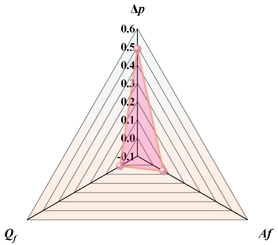
Based on the simulation data from Figure 13, the variation sequences of Af, Qf, and Δptot within their respective operating ranges were extracted. The local derivatives were then calculated using the finite difference method, and the relative rate of change in film thickness h was compared with the relative perturbation rate of each input variable to obtain the normalized sensitivity index Si. To avoid the offset effect caused by local inverse variations, the average of the absolute sensitivity values at all points was taken as the overall sensitivity level of each parameter. The sensitivity results for the corresponding parameters are illustrated in Figure 14.
The results indicate that the pressure gradient Δptot exerts the strongest control over film thickness variation, with a normalized sensitivity coefficient reaching 0.488. Within the current operating range, it exhibits a significant linear enhancement trend, suggesting that Δptot dominates the driving penetration behavior of the lubricant in the interfacial microchannel and is the most influential variable among the three. The sensitivity of the vibration factor Af is 0.065, which, although weaker than Δptot, still plays a reinforcing role in shear spreading and film-formation behavior. The lubricant flow rate Qf shows the lowest sensitivity at only 0.010, indicating that under the present simulation settings its independent regulatory effect is relatively weak, relying more on synergistic adjustment with Af or Δptot. These findings provide a quantitative basis for prioritizing parameter optimization in SCCO2-MQL lubrication systems.

4. Conclusions

This study investigated the lubrication behavior in SCCO2-MQL ultrasonic vibration-assisted milling of SiCp/Al composites and developed a mathematical model of lubrication film thickness that integrates atomization dynamics, capillary permeation, shear spreading, and three-phase modulation mechanisms. Through simulation analysis and experimental validation, the formation mechanism and evolutionary characteristics of the lubrication film were revealed. The main conclusions are as follows:
(1)
A multiphysics-coupled lubrication film thickness prediction model was proposed, systematically characterizing the film-forming behavior of the lubricant under ultrasonic vibration and SCCO2 three-phase conditions. The model integrates droplet atomization scale, lubricant penetration path, shear spreading capacity, and CO2 phase state variation, revealing the key influencing factors and nonlinear response characteristics of film formation, and is finally expressed as a regression-based predictive formulation (Equation (18)), providing a quantitative tool that can be directly applied for subsequent parameter analysis and process optimization.
(2)
A pseudo-phase enhancement factor βps(p,T) was introduced to characterize the phase transition behavior of supercritical CO2 in the critical region. The results reveal that density fluctuations and phase stratification significantly enhance the liquid-phase lubrication capacity, playing a critical role in lubrication film formation and effectively improving film stability and lubrication efficiency.
(3)
Simulation analysis showed that when the vibration factor Af < 1200 μm·kHz, shear spreading is continuously enhanced, whereas exceeding this threshold causes film instability. A pressure gradient Δptot below 6.0 × 10⁵ Pa/m promotes the formation of a complete lubrication film, while excessive values may disrupt the boundary layer. The optimal lubrication effect of the flow rate Qf is observed around 16 mL/h, whereas oversupply may lead to lubricant backflow or film thickness saturation.
(4)
Parameter sensitivity analysis demonstrated that the pressure gradient Δptot is the dominant factor influencing film thickness, with a normalized sensitivity reaching 0.488, which is significantly higher than that of the vibration factor (Af = 0.065) and the flow rate (Qf = 0.010). This indicates that rational regulation of the pressure gradient is the key pathway to improving lubrication performance.

Author Contributions

Writing—review and editing, B.W.; Writing—original draft preparation, H.Z. All authors have read and agreed to the published version of the manuscript.

Funding

This work was supported by the National Natural Science Foundation of China (Grant nos. 52275417).

Data Availability Statement

Data are contained with the arcticle.

Acknowledgments

I would like to express my sincere gratitude to Xinran Wang. During the process of perfecting this thesis, she undertook the tasks of English revision, standardization of terminology, and language normalization, providing crucial support for the thesis to integrate into the international academic context.

Conflicts of Interest

The authors declare no conflicts of interest.

References

  1. Zhu, L.; Wang, Y.; Nie, S.; Huang, H.; Liu, Z. Study on thermal balance of supercritical CO2-assisted machining based on mass flow-rate optimization. J. Mech. Eng. 2018, 60, 367–376. [Google Scholar]
  2. Rong, J.; Niu, Q.; Gao, H.; Jing, L.; Tang, S.; Zhang, S. Optimization of MQL parameters and cutting performance in titanium alloy milling. Aeronaut. Manuf. Technol. 2024, 67, 106–114. [Google Scholar] [CrossRef]
  3. Huan, H.; Luo, T.; Xu, W.; Zhu, C. Surface defects in ultrasonic vibration assisted cutting of TiCp/TC4 with PCD tool. Diam. Abras. Eng. 2023, 43, 672–683. [Google Scholar] [CrossRef]
  4. Yao, C.; Lin, J.; Wu, D.; Ren, J. Surface integrity and fatigue behavior when turning γ-TiAl alloy with optimized PVD-coated carbide inserts. Chin. J. Aeronaut. 2018, 31, 826–836. [Google Scholar] [CrossRef]
  5. Tapoglou, N.; Taylor, C.; Makris, C. Milling of aerospace alloys using supercritical CO2 assisted machining. Procedia CIRP 2021, 101, 370–373. [Google Scholar] [CrossRef]
  6. Wika, K.K.; Gurdal, O.; Litwa, P.; Hitchens, C. Influence of supercritical CO2 cooling on tool wear and cutting forces in the milling of Ti-6Al-4V. Procedia CIRP 2019, 82, 89–94. [Google Scholar] [CrossRef]
  7. Liu, D.; Li, C.; Xu, P.; Wang, W.; Zhang, Y.; Yang, M.; Cui, X.; Li, B.; Liu, M.; Gao, T.; et al. SiCp/Al composites from conventional to empowered machining: Mechanisms and processability. Compos. Struct. 2024, 346, 118433. [Google Scholar] [CrossRef]
  8. Rahim, E.A.; Rahim, A.A.; Ibrahim, M.R.; Mohid, Z. Experimental investigation of supercritical carbon dioxide (SCCO2) performance as a sustainable cooling technique. Procedia CIRP 2016, 40, 637–641. [Google Scholar] [CrossRef]
  9. Yu, W.; Chen, J.; Ming, W.; An, Q.; Chen, M. Feasibility of supercritical CO2-based minimum quantity lubrication to improve the surface integrity of 50% Sip/Al composites. J. Manuf. Process. 2022, 73, 364–374. [Google Scholar] [CrossRef]
  10. Laghari, R.A.; He, N.; Jamil, M.; Gupta, M.K. Tribological and machining characteristics of milling SiCp/Al MMC composites under sustainable cooling conditions. Int. J. Adv. Manuf. Technol. 2023, 128, 2613–2630. [Google Scholar] [CrossRef]
  11. He, Y.; Liu, C.; Wang, Y.; Li, Y.; Wang, S.; Wang, L.; Wang, Y. Analytical modeling of temperature distribution in lead-screw whirling milling considering the transient un-deformed chip geometry. Int. J. Mech. Sci. 2019, 157–158, 619–632. [Google Scholar] [CrossRef]
  12. Williams, J.A.; Tabor, D. The role of lubricants in machining. Wear 1977, 43, 275–292. [Google Scholar] [CrossRef]
  13. Shi, L.; Wang, T.; Liu, E.; Wang, R. Lubrication Mechanism of scCO2-MQL in the Assisted Machining of Titanium Alloys. Machines 2023, 11, 291. [Google Scholar] [CrossRef]
  14. Pei, H. Study on Spray Atomization Characteristics and Permeation Lubrication Mechanism in MQL Cutting. Ph.D. Thesis, Jiangsu University, Zhenjiang, China, 2020. [Google Scholar] [CrossRef]
  15. Banerjee, N.; Sharma, A. Development of a friction model and its application in finite element analysis of minimum quantity lubrication machining of Ti-6Al-4V. J. Mater. Process. Technol. 2016, 238, 181–194. [Google Scholar] [CrossRef]
  16. Ji, X.; Li, B.-Z.; Liang, S.Y. Analysis of Thermal and Mechanical Effects on Residual Stress in Minimum Quantity Lubrication (MQL) Machining. J. Mech. 2018, 34, 41–46. [Google Scholar] [CrossRef]
  17. Jin, J.-X.; Wang, X.-D.; Lee, D.-J. Pseudo-phases of supercritical CO2 at supercritical CO2-subcritical H2O interface: A molecular dynamics simulation. Phys. Fluids 2024, 36, 122026. [Google Scholar] [CrossRef]
  18. Dousti, S. A compressible hydrodynamic analysis of journal bearings lubricated with supercritical carbon dioxide. In Proceedings of the 5th International Symposium on Supercritical CO2 Power Cycles, San Antonio, TX, USA, 28–31 March 2016; pp. 1–10. [Google Scholar]
  19. Wahap, M.A.A.; Nasir, F.M.; Sa’aT, F.A.-Z.M.; Wae-Hayee, M.; Yong, K.T.L.; Anuar, M.R. A comparison of multiphase Ansys-Fluent models in performing supercritical CO2 extraction simulation. CFD Lett. 2025, 17, 182–203. [Google Scholar] [CrossRef]
  20. Tu, L.; Lin, L.; Liu, C.; An, Q.; Ming, W.; Chen, M. Surface layer microstructure and mechanical characteristics analysis of cast iron during milling process under supercritical CO2-MQL. J. Manuf. Process. 2022, 82, 722–737. [Google Scholar] [CrossRef]
  21. Zhang, M.; Zhuang, B.; Wu, B.; Chen, Y.; Zhao, B.; Ding, W.; Su, H. Development of an ultrasonic vibration-assisted MQL device and its effects on the milling performance of ultra-high strength steel. Int. J. Adv. Manuf. Technol. 2024, 135, 4765–4784. [Google Scholar] [CrossRef]
  22. Niu, Q.; Rong, J.; Jing, L.; Gao, H.; Tang, S.; Qiu, X.; Liu, L.; Wang, X.; Dai, F. Study on force-thermal characteristics and cutting performance of titanium alloy milled by ultrasonic vibration and minimum quantity lubrication. J. Manuf. Process. 2023, 95, 115–130. [Google Scholar] [CrossRef]
  23. Verma, G.C.; Pandey, P.M.; Dixit, U.S. An experimental study on surface roughness and frictional property of ultrasonic-vibration-assisted milled surface. Proc. Inst. Mech. Eng. Part C J. Mech. Eng. Sci. 2019, 233, 4187–4198. [Google Scholar] [CrossRef]
  24. Alemayehu, H.; Ghosh, S.; Rao, P.V. Evaluation of Cutting Force and Surface Roughness of Inconel 718 Using a Hybrid Ultrasonic Vibration-Assisted Turning and Minimum Quantity Lubrication (MQL). In Advances in Unconventional Machining and Composites; Springer: Singapore, 2020; pp. 335–346. [Google Scholar] [CrossRef]
  25. Pei, H.J.; Zou, Y.; Liu, C.S.; Wang, G. Experimental study on MQL high-speed turning of 18Cr2Ni4WA alloy steel. Manuf. Technol. Mach. Tool 2017, 120–123. [Google Scholar] [CrossRef]
  26. Jiang, J.; Wu, Z.; Pan, S.; Meng, X.; Liu, D.; Mu, K.; Zhu, Q.; Zhu, J.; Cai, C. High-performance liquid metal-based SiC/Graphene-Mo hybrid nanofluid for hydraulic transmission. Tribol. Int. 2024, 198, 109871. [Google Scholar] [CrossRef]
  27. Bresme, F.; Kornyshev, A.A.; Perkin, S.; Urbakh, M. Electrotunable friction with ionic liquid lubricants. Nat. Mater. 2022, 21, 848–858. [Google Scholar] [CrossRef] [PubMed]
  28. Marian, M.; Bartz, M.; Wartzack, S.; Rosenkranz, A. Non-Dimensional Groups, Film Thickness Equations and Correction Factors for Elastohydrodynamic Lubrication: A Review. Lubricants 2020, 8, 95. [Google Scholar] [CrossRef]
Figure 1. Schematic illustration of SCCO2-MQL ultrasonic vibration-assisted cutting and multiphase flow paths.
Machines 13 00879 g001
Figure 2. Jet stability curve.
Machines 13 00879 g002
Figure 3. Surface oscillation of the jet.
Machines 13 00879 g003
Figure 4. Jet instability and droplet formation.
Machines 13 00879 g004
Figure 5. Relationship between We and de.
Machines 13 00879 g005
Figure 6. Capillary penetration process of cutting fluid within micro-channels.
Machines 13 00879 g006
Figure 7. Velocity profiles of lubricant in the boundary layer at different channel heights.
Machines 13 00879 g007
Figure 8. Periodic response curves of lubricant central velocity vmax(t) under vibration disturbance.
Machines 13 00879 g008
Figure 9. Framework of lubrication film thickness modeling.
Machines 13 00879 g009
Figure 10. Contour distribution of the pseudo-phase enhancement factor βps(p,T) in the P-T space.
Machines 13 00879 g010
Figure 11. Comparison of predicted and actual values of lubrication film thickness.
Machines 13 00879 g011
Figure 12. Residual distribution as a function of the predicted film thickness.
Machines 13 00879 g012
Figure 13. Influence trends of lubrication film thickness h under different parameter conditions.
Machines 13 00879 g013
Figure 14. Sensitivity Analysis.
Machines 13 00879 g014
Disclaimer/Publisher’s Note: The statements, opinions and data contained in all publications are solely those of the individual author(s) and contributor(s) and not of MDPI and/or the editor(s). MDPI and/or the editor(s) disclaim responsibility for any injury to people or property resulting from any ideas, methods, instructions or products referred to in the content.