Abstract
Titanium alloy thin-walled components are extensively used in aerospace engineering, yet their milling stability remains a persistent challenge due to vibration-induced surface anomalies. This study develops an advanced dynamic model for the face milling of titanium alloy thin-walled structures, systematically integrating axial cutting dynamics with regenerative chatter mechanisms and nonlinear process damping phenomena. The proposed framework crucially accounts for time-varying tool–workpiece interactions and damping characteristics, enabling precise characterization of stability transitions under dynamically varying axial immersion conditions. A novel extension of the semi-discretization method is implemented to resolve multi-parameter stability solutions, establishing a computational paradigm for generating three-dimensional stability lobe diagrams (3D SLDs) that concurrently evaluate spindle speed, cutting position, and the axial depth of a cut. Comprehensive experimental validation through time-domain chatter tests demonstrates remarkable consistency between theoretical predictions and empirical chatter thresholds. The results reveal that process damping significantly suppresses chatter at low spindle speeds, while regenerative effects dominate instability at higher speeds. This work provides a systematic framework for optimizing machining parameters in thin-walled component manufacturing, offering improved accuracy in stability prediction compared to traditional two-dimensional SLD methods. The proposed methodology bridges the gap between theoretical dynamics and industrial applications, facilitating efficient high-precision machining of titanium alloys.
1. Introduction
Thin-walled structural components with a large height-to-thickness ratio (about 10:1–50:1) have become indispensable in aerospace engineering due to their exceptional strength-to-mass ratio and design flexibility [1,2]. While milling operations remain the predominant manufacturing method for such components [3,4], the increasing adoption of advanced titanium alloys like Ti-6Al-4V—prized for their superior specific strength, corrosion resistance, and fatigue performance—introduces significant machining challenges. Unlike conventional aluminum alloys, titanium alloys exhibit inherently poor machinability characterized by low thermal conductivity and intense chemical affinity with cutting tools, necessitating restrictive cutting speeds during face milling operations [3]. These constraints, when coupled with the structural compliance of thin-walled workpieces, synergistically amplify dynamic instabilities. The resulting regenerative chatter phenomena manifest as self-excited vibrations that degrade surface integrity, accelerate tool wear, and constrain material removal rates [5]. Current stability prediction models, however, inadequately address the coupled thermo-mechanical effects and time-varying dynamics inherent to titanium alloy thin-wall face milling. This persistent gap underscores the critical need for high-fidelity modeling frameworks that simultaneously account for process damping mechanisms and transient tool–workpiece interactions specific to titanium alloy thin-walled component machining.
The evolution of milling stability prediction methodologies has progressed through the following three distinct developmental phases: frequency-domain analyses, time-domain discretization techniques, and coupled process damping formulations. Foundational frequency-domain approaches, exemplified by Altintas and Budak’s single-frequency method (SFM) [6], established stability lobe diagrams (SLDs) through Fourier series approximations of time-varying cutting coefficients. Subsequent refinements addressed period-doubling bifurcations in serrated tool dynamics [7] and interrupted milling [8], yet they remained constrained by quasi-static assumptions. A paradigm shift toward time-domain methods emerged with Insperger and Stepan’s semi-discretization method (SDM) [9], which inspired derivative techniques including Newton–PTI hybrid algorithms [10], Runge–Kutta enhanced SDM [11], and full-discretization formulations [12,13,14] with state-delay term resolutions. Parallel developments introduced temporal finite element analysis [15] and Newton–Cotes rule-based acceleration [16,17], achieving <5% prediction errors in benchmark cases.
Recent advances have recognized the critical influence of nonlinear process damping (PD) mechanisms—particularly tool flank/workpiece indentation interactions—which stabilize low-speed regimes through equivalent viscous damping effects [18,19,20]. Contemporary models integrate PD with regenerative chatter [21,22], mode coupling [22], and thermomechanical effects [23], while machine learning implementations [24] demonstrate 12–18% improvements in accuracy over conventional SLDs. Nevertheless, these frameworks remain fundamentally limited by two-dimensional parameter spaces (spindle speed vs. axial depth), inadequate for thin-walled component dynamics where structural compliance induces time-varying modal characteristics during machining. This limitation has spurred several three-dimensional stability analysis innovations. Song et al. [25] employed Sherman–Morrison–Woodbury formulations to generate position-dependent SLDs, while Jin et al. [26] incorporated helical tool dynamics in thin-wall 3D lobe predictions. Advanced methodologies now couple structural dynamic modification schemes with mass redistribution strategies [27], multi-point machining path dynamics [28,29], and ball-end mill contact state transitions [30]. Despite these advancements, critical gaps persist in simultaneously addressing process damping in titanium alloys and real-time tool position-dependent stability transitions.
Fixture-mediated stiffness enhancement has emerged as a pivotal strategy for stabilizing thin-walled component machining, with recent innovations spanning passive, active, and adaptive fixture architectures. Topology-optimized fixture configurations [31] demonstrate 40–60% stability improvement through genetic algorithm-driven optimization of support positions and preload forces. For rotational symmetric components, torsion spring-preloaded ancillary devices [32] achieve chatter suppression via controlled energy dissipation. Smart fixture paradigms now integrate magnetorheological fluid layers, achieving vibration attenuation through real-time stiffness modulation [33]; robotic end-effectors, providing position-dependent stiffness compensation [34]; and pneumatic systems, enabling pressure-regulated dynamic support [35]. Breakthrough adaptive solutions eliminate static fixture limitations through moving fixtures with contact-point stiffness tracking [36]. Tool-synchronized clamping systems have been devised, combining (a) real-time machining zone fixation and (b) counter-pressure air jets [37]. These advancements collectively address the stiffness paradox in thin-wall machining—balancing structural compliance for distortion avoidance with localized rigidity for chatter suppression.
While extensive research has established stability prediction frameworks for end milling operations, face milling dynamics—particularly for thin-walled titanium alloys—remain underexplored. Lglesias et al. [38] pioneered a multi-axis coupled stability model for heavy-duty face milling, incorporating workspace kinematics and feed-directional dynamics to achieve cutting force prediction accuracy. Contrasting conventional hammer-impact methods, Shi et al. [39] developed an in-process electromagnetic excitation technique that reduces modal parameter identification errors through real-time frequency response function tracking. Danil’s mechanistic analysis [40] demonstrated that spindle acceleration rates induce fluctuations in face milling stability thresholds due to transient thermal-stress coupling. Das et al. [41] employed hybrid Taguchi–Grey Relational Analysis to optimize Ti6Al4V face milling parameters, demonstrating surface roughness improvement through cutting speed and tool path synchronization. Edelbi’s dual-nozzle MQL system [42] enhanced Ti–3Al–2.5V face milling performance via tool wear reduction through pulsed lubrication, as well as surface integrity improvement through tribofilm formation. Complementing process innovations, Qu et al. [43] established a machine vision-based cutter damage quantification method through multi-spectral illumination compensation and convolutional neural network defect recognition. Notwithstanding this collective progress, critical limitations persist in modeling process damping effects under face milling’s intermittent engagement, as well as in resolving time-varying stability boundaries caused by thin-wall dynamic coupling.
While prior investigations have predominantly focused on stability prediction in conventional milling configurations, a critical knowledge gap persists in addressing the unique dynamic coupling effects inherent to low-speed face milling of titanium alloy thin-walled components—particularly the interplay between process damping and regenerative chatter under subcritical spindle regimes. To bridge this technological void, this study establishes a generalized stability criterion through the following two fundamental innovations:
- A multi-degree-of-freedom face milling dynamics framework is developed, integrating regenerative delay effects with variable immersion kinematics, process damping via tool flank/workpiece indentation mechanics, and time-dependent structural dynamics.
- The conventional semi-discretization method (SDM) is extended through simultaneous discretization of delay differential equations and process damping terms, as well as three-dimensional stability lobe diagrams (3D-SLDs) parameterized by spindle speed, cutting position, and the axial depth of a cut.
The methodological framework comprises the following four principal components: Section 2 formulates the coupled dynamics model, explicitly resolving the process damping in titanium alloys. Section 3 introduces a modified SDM algorithm to calculate stability lobes. Section 4 establishes 3D-SLDs through parametric sweeps across spindle speed, axial cutting depth, and tool position, validated by a series of milling trials. Section 5 concludes the paper.
2. Dynamic Modeling Integrating Regenerative Chatter and Process Damping Effects
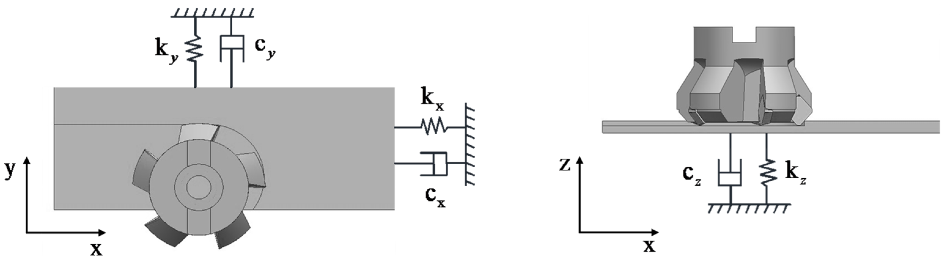
The face milling dynamics, schematically represented in Figure 1, are modeled through a three-degree-of-freedom system considering orthogonal cutting force interactions. Under the rigid-tool assumption, the workpiece’s dynamic compliance dominates vibration characteristics, exhibiting feed (x), transverse (y), and axial (z) directions. Kinematic excitation by periodic cutting forces induces regenerative surface undulations with amplitude modulation characteristics. This phenomenon indicates the potential occurrence of regenerative chatter.
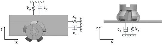
Figure 1.
Schematic representation of thin-wall face milling.
2.1. Cutting Force Modeling
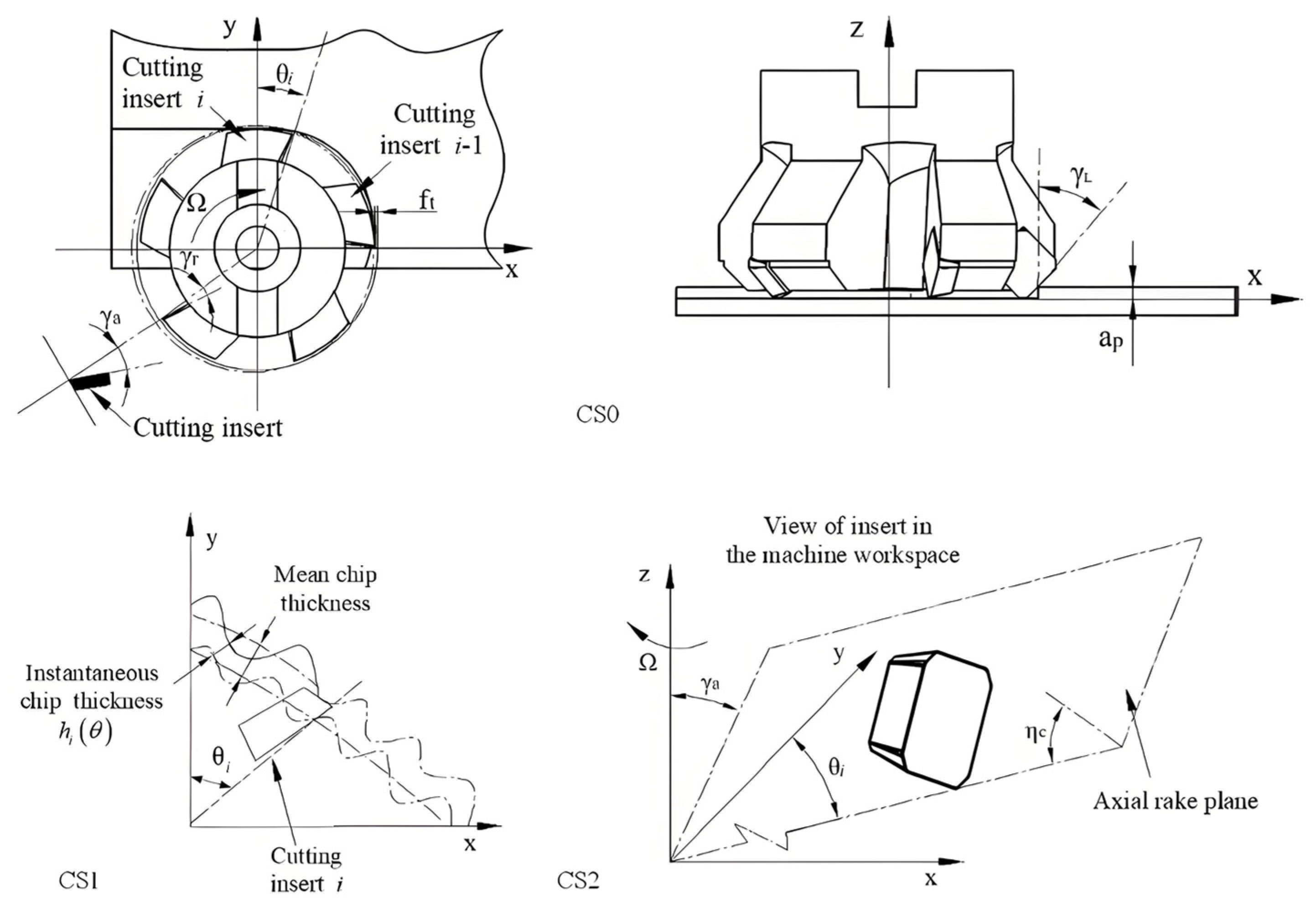
The spatial orientation of the resultant cutting force is governed by multiple interdependent factors, resulting in considerable prediction complexity. To facilitate comprehensive analysis, three distinct coordinate systems are employed for force characterization— CS0, CS1, and CS2.
As illustrated in Figure 2, CS0 denotes the global coordinate system of the cutting tool, with its origin positioned at the bottom center of the tool geometry. In this system, the z-axis is aligned with the spindle axis and oriented perpendicular to the workpiece surface, while the x-axis coincides with the feed direction. The y-axis is subsequently determined by the right-hand rule. Within CS0, the resultant cutting force can be resolved into three orthogonal components—, , and .

Figure 2.
Schematic representation of face milling process geometry and associated coordinate systems.
CS1 represents a local coordinate system defined at the cutting point of each insert, rotating synchronously with the tool. Here, the resultant force is decomposed into three process-relevant components—the tangential force , radial force , and axial force .
Finally, CS2 constitutes a cylindrical coordinate system that corresponds to the insert’s spatial position within the machine workspace. In this framework, the resultant force is expressed in terms of normal force and friction force components acting on the rake face, providing critical insights into tool–chip interaction mechanics.
This multi-coordinate representation enables a systematic examination of cutting forces from global, tool-embedded, and tribological perspectives, enhancing the interpretability of machining dynamics.
The transformation of cutting force components from CS2 to CS1 can be mathematically expressed as follows:
where and represent the radial and axial rake angles of the insert, respectively. denotes the chip flow angle, defined as the angle between the friction force () and the projection of the radial force () in the axial rake plane.
The fundamental cutting forces acting at the tool–chip interface are determined by the product of the instantaneous uncut chip cross-sectional area and the material-specific cutting pressure. This relationship can be formulated as follows:
where is the axial depth of the cut, and represents the actual cutting chip thickness of the i-th tooth when it rotates by an angle of (0 ≤ ≤ 180°). , , and are the tangential, radial, and axial cutting force coefficients, respectively. The cutting force coefficients can be derived from mechanics through the following equations:
Finally, the transformation from CS1 to CS0 is given by the following transformation matrix:
where represents the instantaneous angular position of the i-th cutting insert relative to the y-axis.
2.2. Modeling of Instantaneous Radial Chip Thickness
The chip thickness in milling operations comprises the following two fundamental components: the static chip thickness resulting from nominal feed motion, and the regenerative chip thickness caused by structural vibrations. This relationship can be mathematically expressed as follows:
where is the feed per tooth; τ indicates the time delay; and , and , are the dynamic displacement of cutter and workpiece.
In thin-walled component machining, the effective radial chip thickness exhibits significant variation due to the influence of the tool lead angle on chip formation geometry, workpiece compliance-induced vibrations, and dynamic coupling between cutting forces and structural deflections.
For systems with notable compliance in the axial direction, these effects can substantially alter machining stability boundaries. When considering the i-th cutting tooth at angular position θ, the complete formulation of radial chip thickness in the global coordinate system (CS0) incorporates both tool and workpiece dynamics, as follows:
where , and , are the cutter and workpiece displacements, and , and , are the cutter and workpiece displacements that are imprinted on the surface by the previous tooth at the same point.
2.3. Modeling of Process Damping
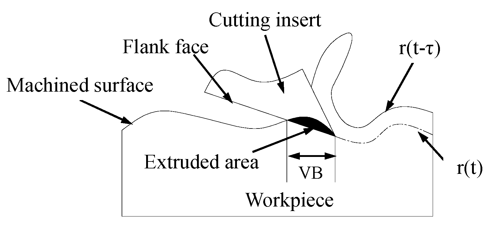
Process damping represents a critical phenomenon in machining dynamics, primarily characterized by the tool flank–workpiece interaction effect. As illustrated in Figure 3, this mechanism occurs when the tool’s flank face engages with the machined surface waviness, significantly enhancing machining stability, particularly in low-speed regimes. Consequently, accurate stability prediction models must incorporate process damping effects for reliable performance estimation.

Figure 3.
Schematic diagram of dynamic milling system with process damping.
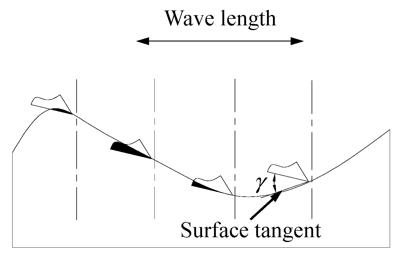
The fundamental physical mechanism of process damping is schematically presented in Figure 4. The analysis reveals the following:
- 1.
- During tool motion from position A to B:
The clearance angle γ decreases progressively;
The plowing volume of extruded material increases correspondingly;
Damping effects intensify proportionally.
- 2.
- During transition from position B to C:
The clearance angle γ increases systematically;
The extruded material volume decreases accordingly;
Damping effects attenuate gradually.
- 3.
- The C-D segment exhibits identical behavioral patterns to B-C, with minimal damping observed at position D.

Figure 4.
Description of mechanism underlying process damping.
Figure 4.
Description of mechanism underlying process damping.
Following the theoretical framework established by Ahmadi and Ismail [44], under the assumption of small amplitude vibrations, the process damping can be modeled as an equivalent linear viscous damper, as follows:
where denotes the specific indentation force coefficient, dependent on workpiece material properties; represents the tangential cutting velocity; and corresponds to the effective tool wear land width, as quantified in Figure 3.
The shape damping factor is derived from tool geometry and surface undulation characteristics. As proposed in [43], this parameter can be expressed as a function of tool wear state, as follows:
where VB is the effective tool wear shown in Figure 3.
2.4. Dynamic Modeling
The synthesized dynamic model of the face milling system, incorporating both regenerative chatter and process damping effects, is formulated as the following delay differential equation (DDE):
where , and represent the modal mass, damping, and stiffness matrices in the x, y, and z directions, respectively. denotes the time delay, equivalent to the tooth passing period, is the time-varying directional dynamic force coefficient matrix with the following elements:
represents the process damping coefficient matrix with the following components:
where μ is the coulomb friction coefficient, and is the unit step function determining tool engagement, which can be expressed as follows:
The start and exit angles vary with milling configuration, as expressed in the following equations:
where a/D is the ratio of radial cutting depth to tool diameter.
3. Three-Dimensional Stability Prediction via Enhanced Semi-Discretization Methodology
The classical semi-discretization method (SDM) developed by Insperger and Stepan [8] provides an effective numerical framework for milling stability analysis, combining computational accuracy with implementation simplicity. This section presents its extension to face milling operations through three key methodological advancements.
The dynamic system (Equation (13)) is transformed into state-space representation, as follows:
where , are T-periodic coefficient matrices (P(t + T) = P(t), Q(t + T) = Q(t)); t refers to the continuous time variable; τ is the discrete time delay; and T is the principal period of coefficient variation.
The solution interval [0, T] is partitioned into k subintervals of length Δt = T/k, where Δt denotes the time increment, with m = int(τ/Δt) determining delay resolution. Within each interval , we consider the following:
where coefficient matrices , are derived via Cauchy transformation of system matrices and weighted averaging of periodic terms; and Δτ is the step size for the discrete time delay.
By Cauchy transformation, Equation (35) can be written as follows:
where the coefficient matrices and are given in the following equations:
The vector and are as follows:
The weights of and are expressed as follows:
Then, the solution of Equation (36) can be obtained, consisting of the general solution and the special solution , as follows:
And the complete solution of the system can be expressed as follows:
Then, by substituting in Equation (44) and establishing as the initial conditions in the i-th interval, the following equation can be obtained:
Since the above results are feasible in the discrete time interval , the following formula can be obtained when :
From the above, it can be seen that depends on , , , , , , , , , , and , but it does not depends on , , , , and . This is because , , and do not appear in Equation (34). In this way, we can obtain the 3m + 6 dimensional state vector, as follows:
instead of the 6m + 6 dimensional vector.
Now, the resulting discrete map can be constructed, as expressed in the following equation:
where the 3m + 6 dimensional coefficient matrix is as follows:
According to Equation (48), the following equation can be obtained:
from which the transition matrix can be identified as follows:
Ultimately, the stability of the face milling system can be determined based on the Floquet theory. If the eigenvalues of are less than one, then the system is stable; otherwise, it will be unstable.
4. Experimental Analysis and Validation
This section systematically validates the proposed 3D stability prediction framework through experimental and analytical investigations on a T-shaped thin-walled titanium alloy (Ti-6Al-4V) workpiece, addressing position-dependent dynamics and stability enhancement strategies.
4.1. Dynamic Modeling of Thin-Wall Workpiece Milling
To establish a tractable dynamic model for face milling of thin-walled structures, the following validated assumptions are adopted:
- Tool–Workpiece Stiffness Disparity: The tool’s axial stiffness dominates the workpiece’s compliance, justifying rigid-tool/flexible-workpiece dynamics.
- Quasi-Static Deformation Exclusion: Dynamic analysis focuses on vibration-induced displacements, omitting static deflection components.
- Cantilever Boundary Condition: The workpiece is modeled as a clamped-free Euler–Bernoulli beam, exhibiting dominant out-of-plane vibrations
- Material Removal Neglect: Stability thresholds are evaluated per pass, assuming negligible mass redistribution during machining.
Under these assumptions, the system dynamics reduce to z-direction vibrations, as governed by the following:
where ϕ(x) represents the modal shape corresponding to the natural mode, normalized to the point of force application in this study, and p(t) is the displacement in the modal space.
For well-separated modes, stability analysis focuses on the primary flexible mode [45], yielding a simplified single-degree-of-freedom (SDOF) system, as follows:
Transforming into state-space representation, as follows:
The stiffness varies with the tool position x, influencing dynamic behavior during milling [46]. And the tool position coordinate x can be defined as in the following equation:
where is the workpiece length; is feed rate; and t is machining time.
As the material removal effect is neglected, both the natural undamped frequency and the damping ratio can be considered constant along the feed direction in a single-pass face milling process. Consequently, three-dimensional stability lobes are required to predict the stability of thin-walled milling operations.
Before calculating these stability lobes, two types of experiments—cutting and dynamic tests—will first be conducted to extract the relevant parameters necessary for an accurate prediction.
4.2. Cutting Tests
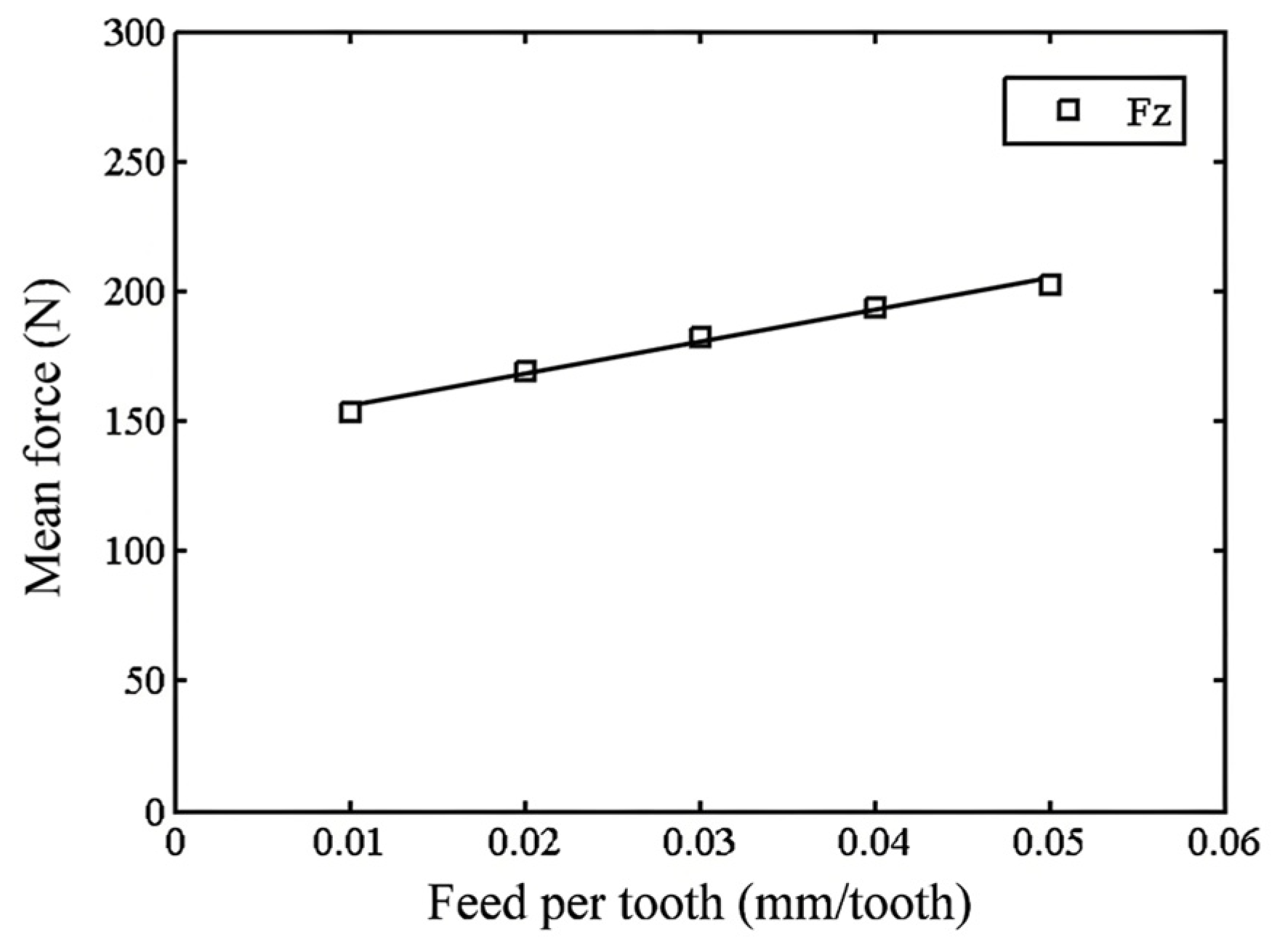
Cutting tests are conducted to determine the cutting force coefficient. A mechanical identification method is employed to obtain the cutting constants based on the average cutting force measured during full-immersion cutting tests, which are performed at various feed rates using a dynamometer. The average cutting constant for full immersion cutting is expressed as follows:
where is the number of teeth; is the feed per tooth; and is the axial depth of the cut. Then, the cutting force coefficient can be determined via linear regression from measured mean force values.
The cutting tests are carried out on a CNC machining center (GJ430), as shown in Figure 5. A titanium workpiece with dimensions of 80 × 80 × 20 mm is mounted on a three-component dynamometer (Kistler 9527B manufactured by Kistler Instrumente AG, located in Winterthur, Switzerland) using a fixture. The dynamometer is positioned on the CNC worktable, and data are collected at a rate of 5000 data points per second. An end-face milling cutter with four inserts is used in this study. The cutter features a 50 mm diameter, a 45° lead angle, a 5° axial rake angle, and a 5° radial rake angle. The cutting tool is made of carbide, and the inserts are made of PVD-coated carbide.
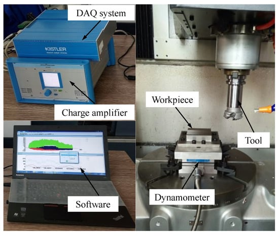
Figure 5.
Experimental setup for cutting tests.
During the cutting tests, the spindle speed and axial cutting depth are kept constant, while the feed per tooth is varied. Five sets of average cutting forces corresponding to different axial feeds are obtained. These values and their associated cutting parameters are presented in Table 1. Linear regression, as shown in Figure 6, is performed to determine the slope of the force vs. feed curve, which enables the calculation of the cutting constants. In this study, the ultimate axial cutting force coefficient is determined to be 4790.9 N/mm2.

Table 1.
Average milling force in z-direction.

Figure 6.
Linear regression results for measured forces.
4.3. Dynamic Tests
The dynamic characteristics of the thin-walled workpiece are determined through experimental modal analysis (EMA) to predict its stability limit. A typical T-shaped cantilever plate, measuring 115 mm × 90 mm × 3 mm (height to thickness is 30:1) and made of titanium alloy (Ti-6Al-4V), is utilized for the experiment.
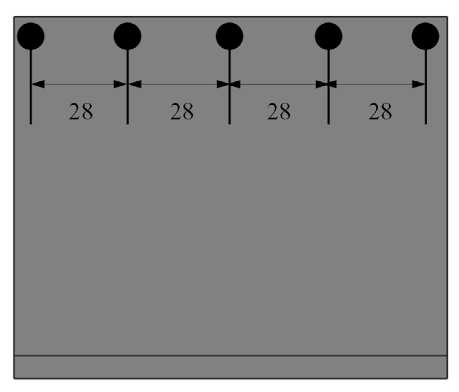
Standard impact tests are performed to acquire the frequency response function (FRF). As outlined in Section 4.1, the dynamic response of the machine structure depends on the position of the tool, and thus the FRF must be measured at each tool position. While increasing the number of measurement positions enhances the accuracy of the results, it also complicates the EMA process. To strike a balance, FRF measurements are taken at five distinct locations, as illustrated in Figure 7. These measurement points are strategically selected to avoid modal nodes and ensure the capture of all significant modes. Notably, points 1 and 5, as well as points 2 and 4, are symmetric, meaning their corresponding FRFs are identical.
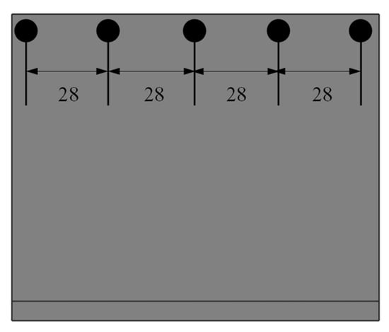
Figure 7.
Measuring points on workpiece.
The experimental setup for the dynamic tests is depicted in Figure 8. An impact hammer (PCB 086C manufactured by PCB Piezotronics, located in Depew, NY, USA) is employed to excite the test structure, while a miniature accelerometer (PCB 356A manufactured by PCB Piezotronics, located in Depew, NY, USA., 1g in weight, with a maximum sampling frequency of 8 kHz) is used to record the response of the thin-walled workpiece. Each measurement point is struck five times to minimize noise interference. The response and force signals are collected using the LMS data acquisition system and processed with LMS Test.Lab 14A software. This procedure yields the FRFs of the workpiece, allowing for the identification of modal parameters.
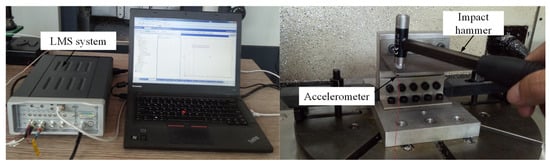
Figure 8.
Experimental setup for dynamic tests.
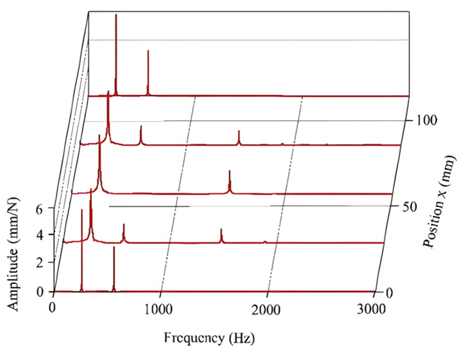
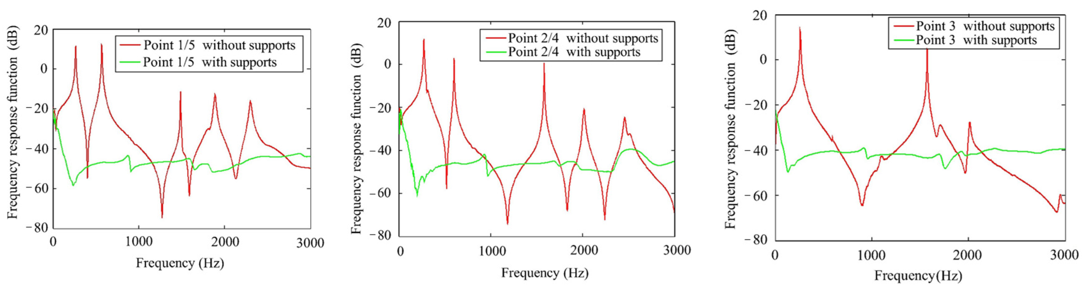
The direct FRFs measured at the five locations are shown in Figure 9. It is observed that only the first two modes (corresponding to points 1/5 and 3) or the first three modes (corresponding to points 2/4) of the workpiece fall within the sampling bandwidth, and these modes are well separated. The identified modal parameters are summarized in Table 2.
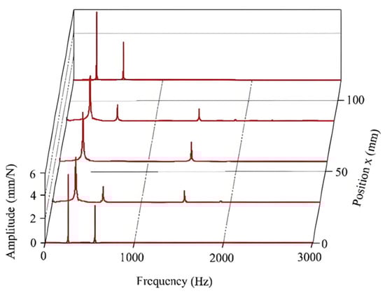
Figure 9.
Direct FRFs measured at different positions.
Table 2.
Modal parameters of thin-walled workpiece.
4.4. Stability Prediction Based on 3D Lobe Diagrams
Following the completion of the dynamic tests, the relevant cutting force coefficients and modal parameters are accurately determined. To construct the stability lobes, the following additional parameters are incorporated: = 0.05 mm/tooth, a/D = 0.5, = 30,000 N/mm3 [19], μ = 0.3, and VB = 0.08 mm. Additionally, up-milling is chosen as the milling mode. Utilizing the proposed method and employing MATLAB 2014a software for calculations, the 3D stability lobes for the thin-walled workpiece are established, as shown in Figure 10.
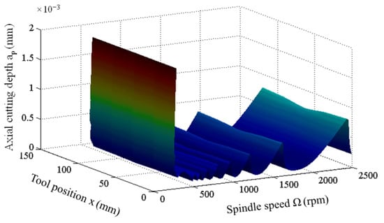
Figure 10.
3D stability lobes of thin-walled workpiece.
It is evident that the axial limit depth of cut is influenced by two primary factors—the spindle speed and the relative position of the tool. In the context of stability evaluation, similar to traditional 2D lobe diagrams, the region beneath the curved surface indicates stable cutting conditions, while the area above the surface signifies unstable cutting conditions. However, a significant distinction in the 3D lobe diagram is the inclusion of a third axis, which illustrates the variation in the stability limit curve with respect to the tool position during the milling process of flexible components. This feature enables the selection of optimal machining parameters, ensuring stable cutting throughout the entire milling operation and facilitating the achievement of the maximum material removal rate.
It is observed that the critical stability limit is relatively low. Nevertheless, below 500 rpm, the critical stability limit exhibits an upward trend, suggesting that process damping plays a role in enhancing stability during low-speed machining. Given the low stability limit, it is crucial to implement strategies that improve the overall stability of the milling process.
4.5. Stability Improvement Strategy
In practical engineering applications, the incorporation of an auxiliary support is a widely adopted method to enhance the stability of dynamic systems. In this section, we investigate the effect of adding supports to the rear surface of a thin-walled workpiece to improve its dynamic characteristics. As illustrated in Figure 11, three auxiliary supports are strategically placed to reinforce the stability of the structure, where (a) is the overall view of the structure, showing the complete effect, and (b) is the schematic diagram specifically illustrating the positioning of the additional supports.
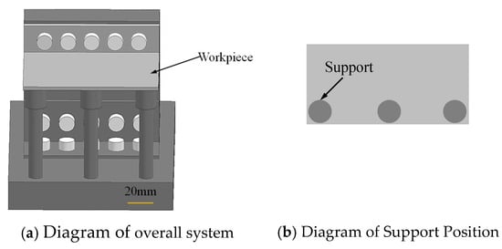
Figure 11.
Modification of the thin-walled workpiece by the addition of three auxiliary supports.
Similar to the cases without supports, dynamic tests are conducted with supports, and the results are presented in Figure 12. To facilitate a clear comparison of the dynamic behavior with and without support, the FRFs of the original structure are also shown in Figure 12. It is observed that the vibration amplitudes are significantly reduced when supports are added, leading to a noticeable improvement in the stability of the milling process.

Figure 12.
FRFs measured at various points for structure with and without supports.
The 3D stability lobes for the supported structure are derived using the same procedure as for the original configuration, with the results displayed in Figure 13. Notably, the critical depth of cut is substantially enhanced by the addition of the auxiliary supports, indicating a marked improvement in the stability performance of the milling process.
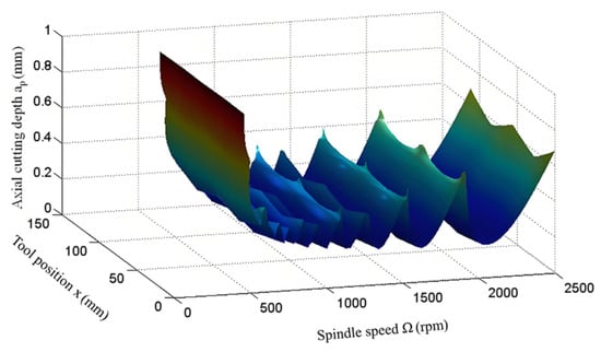
Figure 13.
3D stability lobes of the thin-walled workpiece with supports.
4.6. Experimental Verification
To validate the feasibility of the established stability lobes, a series of machining experiments are conducted with various combinations of spindle speeds and axial cutting depths. The milling operations are performed according to the experimental setup depicted in Figure 14. Sound signals generated during the machining process are captured using a microphone. These sound signals are subsequently processed using Fast Fourier Transform (FFT) to obtain their frequency spectra, which are then analyzed to assess cutting stability. If the sound spectrum is dominated by multiples of the spindle and tooth passing frequencies, the process is considered stable; otherwise, it is deemed unstable.
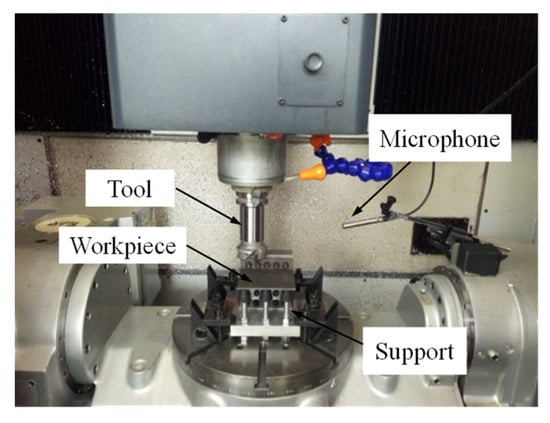
Figure 14.
Experimental setup for milling operations.
The stiffness at points 2 and 4 is lower than at the other positions, resulting in lower predicted stability lobes at these locations. Throughout the entire cutting process, the stability lobes at these two points play a critical role in optimizing the milling parameters to ensure the maximum material removal rate (MRR). Since points 2 and 4 are symmetrical, the experimentally observed stability results at point 2 are summarized in Figure 15. In this figure, circles represent stable cases, while crosses correspond to chatter cases. It is evident that the experimental results align reasonably well with the simulation stability lobes, taking process damping into account. Only a few discrepancies are observed, such as at 500 rpm and 0.4 mm, as well as at 600 rpm and 0.25 mm. These inconsistencies can be attributed to their proximity to the stability boundary, making them susceptible to uncertainties such as the processing environment and machine system variations.
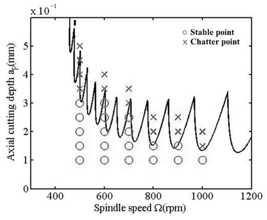
Figure 15.
Stability lobes at point 2.
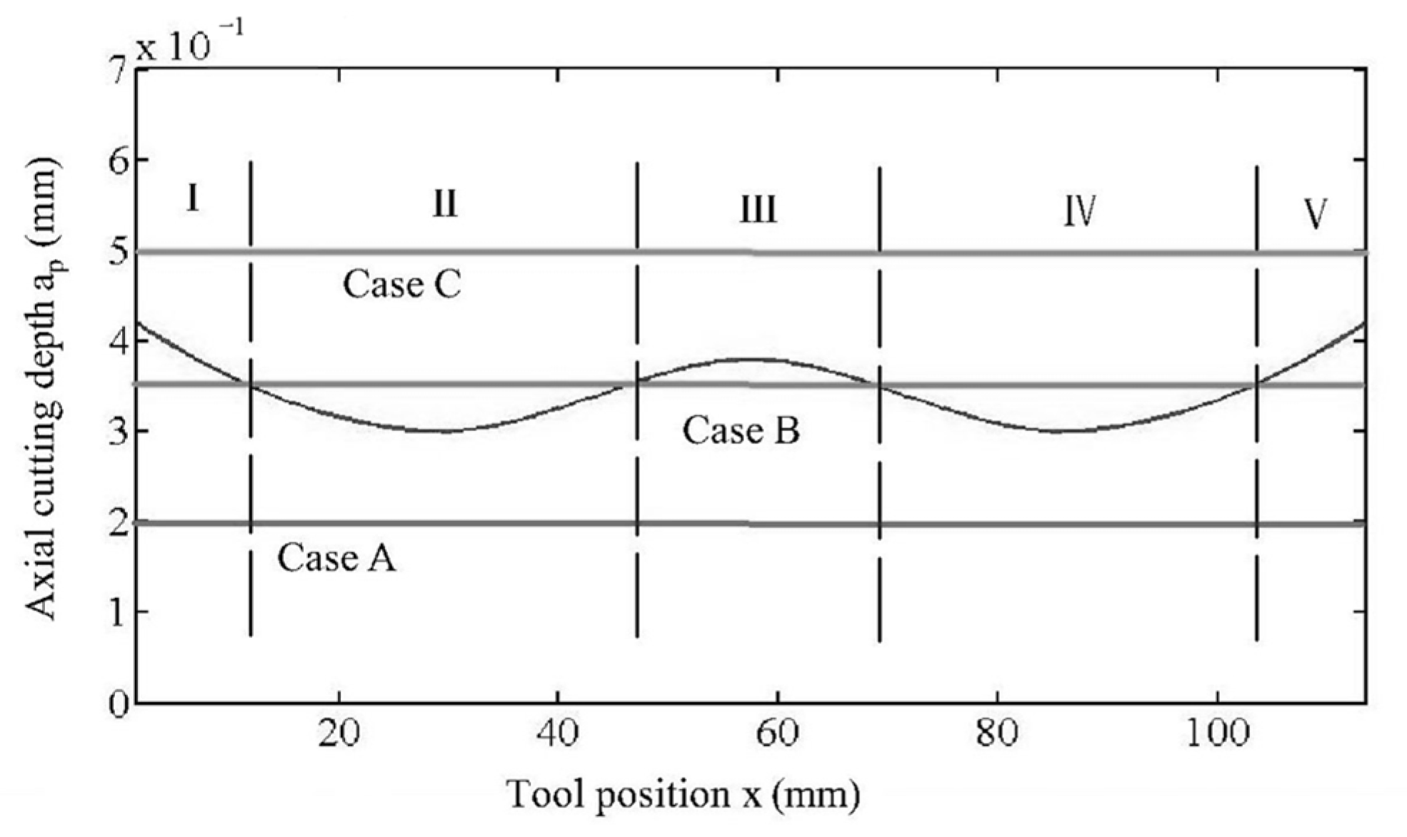
To provide further clarity, three typical parameter combinations were selected for analysis, including 700 rpm and 0.2 mm (case A); 700 rpm and 0.35 mm (case B); and 700 rpm and 0.5 mm (case C). In order to observe the variation in critical stability limits along the relative position, a cross-sectional profile is extracted from the 3D stability lobe by fixing the spindle speed at Ω = 700 rpm, as shown in Figure 16. The critical stability limit exhibits a trend characterized by a decrease, followed by a rise, a subsequent decrease, and a final increase. To facilitate an intuitive comparison of the experimental results for these three cases, the machined surface quality and the sound signals, along with their corresponding spectra, are presented in Figure 17, Figure 18 and Figure 19.

Figure 16.
A section of 3D stability lobe at Ω = 700 rpm.
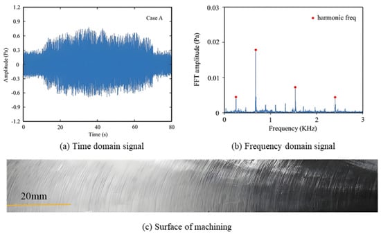
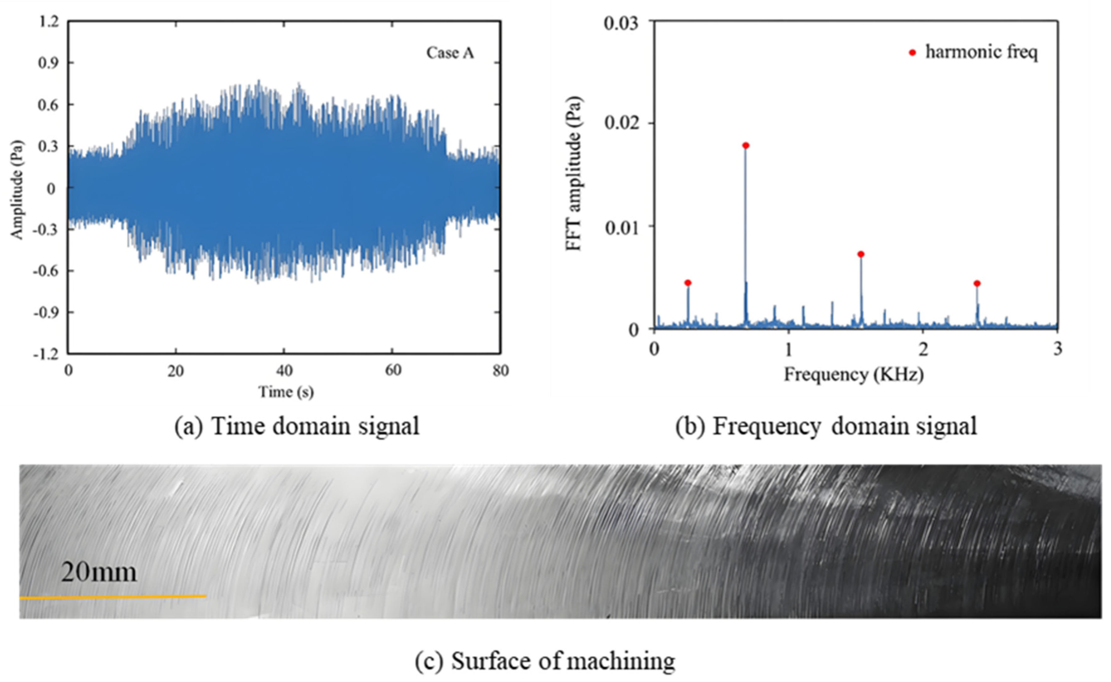
Figure 17.
Cutting results of case A.
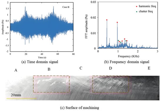
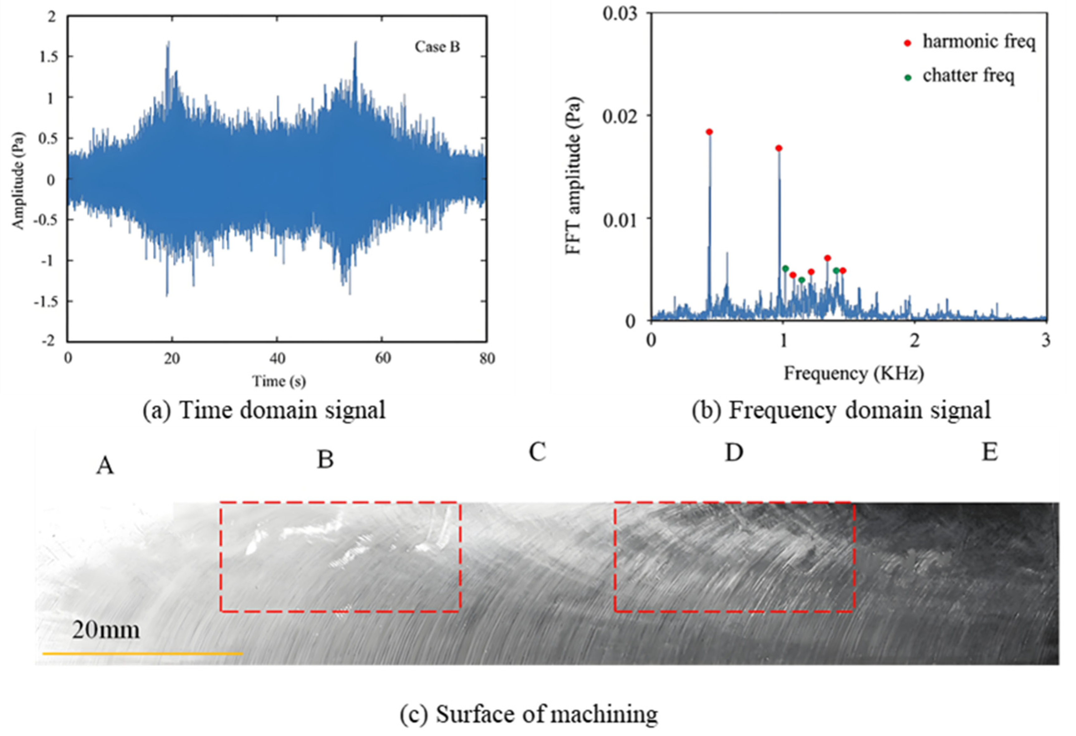
Figure 18.
Cutting results of case B.
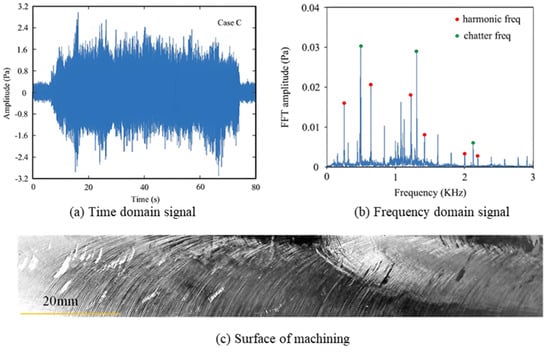
Figure 19.
Cutting results of case C.
During the experiment, the measurement process involves capturing both the machined surface quality and the acoustic signal during machining. Frequency domain data are obtained from acoustic signals collected using a microphone (GRAS 46AE manufactured by GRAS Sound & Vibration, located in Lynge, Denmark, which has a sensitivity of 50 mV/Pa), and the machined surface is then analyzed for vibration marks. These data are then processed and analyzed to identify the presence of chatter. Specifically, the appearance of vibration marks on the machined surface and the presence of chatter frequencies in the frequency domain signal indicate the onset of chatter. Conversely, the absence of vibration marks on the machined surface and the presence of only the tooth passing frequency and its harmonics in the frequency domain signal confirm the absence of chatter.
For case A (700 rpm, 0.2 mm), as shown in Figure 17a, no chatter marks are visible on the machined surface, indicating a stable and chatter-free process across the entire cutting position. In Figure 17b, the sound signals remain essentially constant throughout the process. Furthermore, as depicted in Figure 17c, the sound spectra are dominated by multiples of the tooth passing frequency (NΩ/60 = 46.7 Hz), with no chatter frequencies present. These observations suggest that the axial cutting depth of 0.2 mm is below the critical stability limit, resulting in stable milling, which is consistent with the theoretical predictions.
For case B (700 rpm, 0.35 mm), Figure 18 shows that the machining process is stable in three regions —on both sides and in the middle of the workpiece. However, instability is observed in the second and fourth regions, leading to alternating stable and unstable cutting conditions. In Figure 18a, clear chatter marks are visible in regions B and D, while no such marks appear in the other regions, which aligns with the predicted results. More convincingly, the measured sound signals, as shown in Figure 18b, exhibit variations that correspond to the predicted stability changes. Additionally, the sound spectra for region B, as shown in Figure 18c, clearly display the presence of chatter frequencies. Due to the symmetry of the process, the sound spectra in region D are similar to those in region B, further confirming the accuracy of the prediction.
For case C (700 rpm, 0.5 mm), instability is predicted across all relative tool positions. As shown in Figure 19a, chatter marks are evident across the entire machined surface. Moreover, as depicted in Figure 19b,c, the sound signals exhibit a significant increase, and chatter frequencies are clearly discernible in the sound spectra. These results strongly corroborate the prediction that the milling process is unstable for this particular parameter combination.
5. Conclusions
This study introduces a novel analytical model for predicting stability limits in end-face milling operations, explicitly incorporating the effects of regeneration and process damping. A 3D stability lobe diagram, which accounts for the tool position, is developed as a practical tool for selecting optimal cutting parameters, particularly for thin-wall milling processes. Additionally, the integration of three auxiliary supports significantly improves the overall system stability. The effectiveness of the proposed method is validated through a series of controlled experiments. These experiments assess the stability of the milling process by examining the quality of the machined surface and analyzing the measured sound signals. The key findings of this study demonstrate the potential of the proposed model to enhance stability prediction and optimize cutting conditions in practical milling applications.
The experimental results show strong agreement with the theoretical predictions. The key conclusions drawn from this research are as follows:
- Axial Force Significance: In the end-face milling of thin-walled workpieces, the axial force plays a crucial role and cannot be neglected when compared to the forces in the other two directions. It significantly influences the system’s stability. To account for this, the dynamic cutting force model proposed in this paper integrates the instantaneous dynamic uncut chip thickness in all three directions.
- Impact of Process Damping: Process damping has a substantial effect on machining stability. A dynamic model that incorporates milling damping is developed, and stability lobes are predicted based on this model. The accuracy of the proposed model is validated by experimental results, particularly in the case of difficult-to-machine materials such as Ti-6Al-4V.
- Effectiveness of Auxiliary Supports: The dynamic machinability of thin-walled components is significantly improved by adding auxiliary supports to the back of the workpiece. This method proves to be an effective strategy for enhancing cutting efficiency, particularly by optimizing cutting parameters in the milling of thin-walled parts.
Author Contributions
Methodology, investigation, software, and writing—original draft: J.J. Data curation, validation, and writing—review and editing: L.C. Visualization and writing—review and editing: W.S. Writing—review and editing and supervision: M.H. All authors have read and agreed to the published version of the manuscript.
Funding
This research received no external funding.
Data Availability Statement
Data and materials used in this research are available.
Conflicts of Interest
All authors were employed by the company Chengdu Aircraft Industrial (Group) Co., Ltd. They declare that the research was conducted in the absence of any commercial or financial relationships that could be construed as a potential conflict of interest.
References
- Sun, Y.W.; Zheng, M.; Jiang, S.L.; Zhan, D.N.; Wang, R.Q. A State-of-the-Art Review on Chatter Stability in Machining Thin-Walled Parts. Machines 2023, 11, 359. [Google Scholar] [CrossRef]
- Del Sol, I.; Rivero, A.; López de Lacalle, L.N.; Gamez, A.J. Thin-Wall Machining of Light Alloys: A Review of Models and Industrial Approaches. Materials 2019, 12, 2012. [Google Scholar] [CrossRef]
- Pramanik, A. Problems and solutions in machining of titanium alloys. Int. J. Adv. Manuf. Technol. 2014, 70, 919–928. [Google Scholar] [CrossRef]
- Guo, Q.; Liu, Z.L.; Yang, Z.; Yang, Z.; Sun, Y.W.; Xu, J.T. Development, challenges and future trends on the fabrication of micro-textured surfaces using milling technology. J. Manuf. Process. 2024, 126, 285–331. [Google Scholar] [CrossRef]
- Munoa, J.; Beudaert, X.; Dombovari, Z.; Altintas, Y.; Budak, E.; Brecher, C.; Stepan, G. Chatter suppression techniques in metal cutting. CIRP Ann. 2016, 65, 785–808. [Google Scholar] [CrossRef]
- Altintaş, Y.; Budak, E. Analytical prediction of stability lobes in milling. CIRP Ann. 1995, 44, 357–362. [Google Scholar] [CrossRef]
- Farahani, N.D.; Altintas, Y. Chatter stability of serrated milling tools in frequency domain. J. Manuf. Sci. Eng. Trans. ASME 2022, 144, 031013–031021. [Google Scholar] [CrossRef]
- Sanz-Calle, M.; Munoa, J.; Iglesias, A.; Lopez, de.; Lacalle, L.N.; Dombovari, Z. Semianalytic stability algorithm in the frequency domain for interrupted milling. Int. J. Mach. Tools Manuf. 2023, 187, 104005. [Google Scholar] [CrossRef]
- Insperger, T.; Stépán, G. Updated semi-discretization method for periodic delay-differential equations with discrete delay. Int. J. Numer. Methods Eng. 2004, 61, 117–141. [Google Scholar] [CrossRef]
- Jiang, S.L.; Sun, Y.W.; Yuan, X.L.; Liu, W.R. A second-order semi-discretization method for the efficient and accurate stability prediction of milling process. Int. J. Adv. Manuf. Technol. 2017, 92, 583–595. [Google Scholar] [CrossRef]
- Guo, M.X.; Zhu, L.D.; Yan, B.L.; Guan, Z.H. Research on the milling stability of thin-walled parts based on the semi discretization method of improved Runge-Kutta method. Int. J. Adv. Manuf. Technol. 2021, 115, 2325–2342. [Google Scholar] [CrossRef]
- Ding, Y.; Zhu, L.M.; Zhang, X.J.; Ding, H. On a numerical method for simultaneous prediction of stability and surface location error in low radial immersion milling. J. Dyn. Sys. Meas. Control ASME 2011, 133, 024503. [Google Scholar] [CrossRef]
- Quo, Q.; Sun, Y.; Jiang, Y. On the accurate calculation of milling stability limits using third-order full-discretization method. Int. J. Mach. Tools Manuf. 2012, 62, 61–66. [Google Scholar] [CrossRef]
- Ji, Y.J.; Wang, L.Y.; Song, Y.; Wang, H.J.; Liu, Z.B. Investigation of robotic milling chatter stability prediction under different cutter orientations by an updated full-discretization method. J. Sound Vib. 2022, 536, 117150. [Google Scholar] [CrossRef]
- Bayly, P.V.; Halley, J.E.; Mann, B.P.; Davies, M.A. Stability of interrupted cutting by temporal finite element analysis. J. Manuf. Sci. Eng. 2003, 125, 220–225. [Google Scholar] [CrossRef]
- Li, W.T.; Wang, L.P.; Yu, G. An accurate and fast milling stability prediction approach based on the Newton-Cotes rules. Int. J. Mech. Sci. 2020, 177, 105469. [Google Scholar] [CrossRef]
- Liu, W.C.; Yang, W.A.; Chen, Y.X.; You, Y.P. A novel precise integration-based updated numerical integration method for milling stability prediction. Int. J. Adv. Manuf. Technol. 2023, 124, 21092126. [Google Scholar] [CrossRef]
- Liu, B.G.; Zhu, L.D.; Dun, Y.C.; Liu, C.F. Investigation on chatter stability of thin-walled parts in milling based on process damping with relative transfer functions. Int. J. Adv. Manuf. Technol. 2017, 89, 2701–2711. [Google Scholar] [CrossRef]
- Ahmadi, K.; Ismail, F. Stability lobes in milling including process damping and utilizing Multi-Frequency and Semi-Discretization Methods. Int. J. Mach. Tools Manuf. 2012, 54–55, 46–54. [Google Scholar] [CrossRef]
- Tunç, L.T.; Budak, E. Identification and modeling of process damping in milling. J. Manuf. Sci. Eng. 2013, 135, 021001. [Google Scholar] [CrossRef]
- Li, Z.Y.; Sun, Y.W.; Guo, D.M. Chatter prediction utilizing stability lobes with process damping in finish milling of titanium alloy thin-walled workpiece. Int. J. Adv. Manuf. Technol. 2017, 89, 2663–2674. [Google Scholar] [CrossRef]
- Ji, Y.J.; Wang, X.B.; Liu, Z.B.; Wang, H.J.; Jiao, L.; Zhang, L.; Huang, T. Milling stability prediction with simultaneously considering the multiple factors coupling effects-regenerative effect, mode coupling, and process damping. Int. J. Adv. Manuf. Technol. 2018, 97, 2509–2527. [Google Scholar] [CrossRef]
- Trivikrama Raju, C.; Jakeer Hussain, S.; Yedukondalu, G. Numerical Simulations of the Cutting Forces in an End Milling Process with Process Damping, Tool Runout and Variable Pitch Effects. In International Conference on Intelligent Manufacturing and Energy Sustainability; Springer: Singapore, 2023; Volume 372, pp. 437–447. [Google Scholar]
- Schmitz, T. Physics-informed KNN milling stability model with process damping effects. J. Manuf. Process. 2024, 120, 1124–1129. [Google Scholar] [CrossRef]
- Song, Q.H.; Liu, Z.Q.; Wan, Y.; Ju, G.G.; Shi, J.H. Application of Sherman–Morrison–Woodbury formulas in instantaneous dynamic of peripheral milling for thin-walled component. Int. J. Mech. Sci. 2015, 96–97, 79–90. [Google Scholar] [CrossRef]
- Jin, X.; Sun, Y.W.; Guo, Q.; Guo, D.M. 3D stability lobe considering the helix angle effect in thin-wall milling. Int. J. Adv. Manuf. Technol. 2015, 82, 2123–2136. [Google Scholar] [CrossRef]
- Wan, M.; Dang, X.B.; Zhang, W.H.; Yang, Y. Optimization and improvement of stable processing condition by attaching additional masses for milling of thin-walled workpiece. Mech. Syst. Signal Process. 2018, 103, 196–215. [Google Scholar] [CrossRef]
- Deng, J.; Wang, F.J.; Fu, R.; Lin, Y.Q.; He, Q.S.; Ma, X. Prediction of time-varying dynamics and chatter stability analysis for surface milling of thin-walled curved CFRP workpiece. J. Mater. Process. Tech. 2023, 322, 118186. [Google Scholar] [CrossRef]
- Campa, F.J.; Lopez de Lacalle, L.N.; Celaya, A. Chatter avoidance in the milling of thin floors with bull-nose end mills: Model and stability diagrams. Int. J. Mach. Tools Manuf. 2011, 51, 43–53. [Google Scholar] [CrossRef]
- Wu, Y.W.; Xiao, J.L.; Tian, Y.; Mao, Y.G.; Liu, S.J.; Liu, H.T.; Huang, T. Vibration suppression of balls in different contact states during mirror milling of curved thin-walled parts based on magnetic follow-up support fixture. J. Manuf. Process. 2024, 131, 2323–2339. [Google Scholar] [CrossRef]
- Zeng, S.; Wan, X.; Li, W.; Yin, Z.; Xiong, Y. A novel approach to fixture design on suppressing machining vibration of flexible workpiece. Int. J. Mach. Tools Manuf. 2012, 58, 29–43. [Google Scholar] [CrossRef]
- Kolluru, K.; Axinte, D. Novel ancillary device for minimising machining vibrations in thin wall assemblies. Int. J. Mach. Tools Manuf. 2014, 85, 79–86. [Google Scholar] [CrossRef]
- Ma, J.; Zhang, D.; Wu, B.; Luo, M.; Chen, B. Vibration suppression of thin-walled workpiece machining considering external damping properties based on magnetorheological fluids flexible fixture. Chin. J. Aeronaut. 2016, 29, 1074–1083. [Google Scholar] [CrossRef]
- Ozturk, E.; Barrios, A.; Sun, C.; Rajabi, S.; Munoa, J. Robotic assisted milling for increased productivity. CIRP Ann. 2018, 1764, 4. [Google Scholar] [CrossRef]
- Jia, J.; Niu, J.; Sun, Y. Dynamics modeling and stability improvement in the machining of thin-walled workpiece with force-tunable pneumatic fixture. Int. J. Adv. Manuf. Technol. 2021, 117, 1029–1043. [Google Scholar] [CrossRef]
- Wan, M.; Dang, X.B.; Zhang, W.H.; Yang, Y. Chatter suppression in the milling process of the weakly-rigid workpiece through a moving fixture. J. Mater. Process. Technol. 2022, 299, 117293. [Google Scholar] [CrossRef]
- Tian, Y.; Xiao, J.L.; Liu, S.J.; Ma, S.J.; Liu, H.T.; Huang, T. Vibration and deformation suppression in mirror milling of thin-walled workpiece through a magnetic follow-up support fixture. J. Manuf. Process. 2023, 99, 168–183. [Google Scholar] [CrossRef]
- Iglesias, A.; Munoa, J.; Ciurana, J. Optimization of face milling operations with structural chatter using a stability model based on process planning methodology. Int. J. Adv. Manuf. Technol. 2014, 70, 559–571. [Google Scholar] [CrossRef]
- Shi, Z.Y.; Liu, L.N.; Liu, Z.Q.; Zhang, X.Z. Frequency-domain stability lobe prediction for high-speed face milling process under tool-workpiece dynamic interaction. J. Eng. Manuf. 2017, 231, 2336–2346. [Google Scholar] [CrossRef]
- Danil, Y.P.; Amauri, H.; Szymon, W.; Mozammel, M.; Aristides, M.; Daniel, I.; Suyama, A.B.; Grzegorz, K.; Munish, K.G. Effect of the Relative Position of the Face Milling Tool towards the Workpiece on Machined Surface Roughness and Milling Dynamics. Appl. Sci. 2019, 9, 842. [Google Scholar]
- Layatitdev, D.; Rakesh, N.; Kuldeep, K.S.; Jajneswar, N.; Shakti, P.J.; Ajit, B.; Shankar, S.C.P.; Saurav, D.; Dalael, S.A. Determination of Optimum Machining Parameters for Face Milling Process of Ti6A14V Metal Matrix Composite. Materials 2022, 15, 4765. [Google Scholar]
- Edelbi, A.; Kumar, R.; Sahoo, A.K.; Pandey, A. Comparative Machining Performance Investigation of Dual-Nozzle MQL-Assisted ZnO and Al2O3 Nanofluids in Face Milling of Ti–3Al–2.5V Alloys. Arab. J. Sci. Eng. 2023, 48, 2969–2993. [Google Scholar] [CrossRef]
- Qu, J.; Yue, C.; Zhou, J.; Xia, W.; Liu, X.; Liang, S.Y. On-machine detection of face milling cutter damage based on machine vision. Int. J. Adv. Manuf. Technol. 2024, 133, 1865–1879. [Google Scholar] [CrossRef]
- Ahmadi, K.; Ismail, F. Analytical stability lobes including nonlinear process damping effect on machining chatter. Int. J. Mach. Tools Manuf. 2011, 51, 296–308. [Google Scholar] [CrossRef]
- Wan, M.; Ma, Y.C.; Zhang, W.H.; Yang, Y. Study on the construction mechanism of stability lobes in milling process with multiple modes. Int. J. Adv. Manuf. Technol. 2015, 79, 589–603. [Google Scholar] [CrossRef]
- Zhan, D.N.; Lu, D.W.; Gao, W.X.; Wei, H.J.; Sun, Y.W. Chatter Detection in Thin-Wall Milling Based on Multi-Sensor Fusion and Dual-Stream Residual Attention CNN. Machines 2024, 12, 559. [Google Scholar] [CrossRef]


Disclaimer/Publisher’s Note: The statements, opinions and data contained in all publications are solely those of the individual author(s) and contributor(s) and not of MDPI and/or the editor(s). MDPI and/or the editor(s) disclaim responsibility for any injury to people or property resulting from any ideas, methods, instructions or products referred to in the content. |
© 2025 by the authors. Licensee MDPI, Basel, Switzerland. This article is an open access article distributed under the terms and conditions of the Creative Commons Attribution (CC BY) license (https://creativecommons.org/licenses/by/4.0/).