Abstract
The effects of boundary conditions on the vibration characteristics of a sandwich plate with viscoelastic periodic cores were examined. The tangential, vertical, transverse, and torsional springs were utilized to restrict the sandwich plate’s edge in order to model a general boundary condition, bringing the benefit that the conventional free, clamped, and simply supported boundary conditions became special cases in the proposed model as these spring constants took extreme values. A theoretical model was established to calculate the forced response and band structure of the periodic sandwich plate, providing computational support for evaluating its vibration characteristics. The correctness of the theoretical model was also validated by the finite element method. The results show that the boundary spring stiffness has a significant effect on the band-gap frequencies and band-gap width of the periodic sandwich plate. Increasing the boundary spring stiffness contributes to achieving broader band gaps. In addition, the band-gap frequencies and band-gap width are more sensitive to transverse spring stiffness than the tangential, vertical, and torsional spring stiffnesses. Therefore, changing transverse spring stiffness is more effective for adjusting the band gap property. This study may provide helpful guidance on vibration and noise reduction design in engineering.
1. Introduction
Over the past two to three decades, emerging structures, including periodic structures [1,2], phononic crystals [3,4], and metamaterials [5], have gradually garnered widespread attention from researchers. Periodic structures are composed of identical structural units arranged in a certain periodic order. In traditional engineering, the design of periodic structures usually focuses on mechanical performance. However, the emergence and development of phononic crystals and metamaterials have further expanded the scope of periodic structures. The periodicity of the structure gives it filtering characteristics [6], meaning that vibrational waves within the band gap are unable to propagate freely and are suppressed, while waves outside the band-gap frequency range can propagate normally. Due to the suppression of vibrations, the radiation noise within the bandgap is also significantly reduced, making periodic structures a new method for controlling structural vibrations and noise.
The Bragg-scattering band-gap formation mechanism was the earliest discovered and studied mechanism [7,8]. Its most straightforward understanding can be regarded as an impedance mismatch caused by material or geometric discontinuities at specific positions in the periodic structure. During wave propagation, the impedance mismatch causes energy redistribution, with some of the energy being reflected and the remainder transmitted. When waves are periodically reflected and transmitted, complex superposition, destructive, and constructive interference effects occur among multiple reflected and transmitted waves, causing specific frequencies to weaken gradually during forward propagation, resulting in band-gap phenomena.
As beam structures are commonly used in engineering, when the study of periodic structures transitions from discrete oscillators to continuous elastic systems, periodic beam structures have been extensively researched [9,10,11,12]. In studies of periodic beams and plates, initial focus was generally on one-dimensional periodic beams, with later extensions to two-dimensional periodic plates as research matured [13,14,15,16,17]. Early research primarily focused on widely used engineering structures, such as periodic support [18], periodic added point masses [19], periodic stiffening [20], and periodic gratings [21]. With the development of phononic crystals and acoustic metamaterials, a wider range of periodic beam and plate types has emerged.
Materials with periodic variations have been widely studied in the context of periodic beams and plates. Wen et al. investigated the bending vibrations of periodic thin beams made of acrylic and aluminum materials, exploring the band-gap characteristics based on Bragg scattering phononic crystal Euler beams [22]. Liu et al. transformed straight beams into curved beams to analyze in-plane and out-of-plane vibration band gaps of periodic curved beams, observing some differences compared to straight beams [23]. Based on bending-vibration research, Fang et al. further considered torsional vibrations, studied the energy band structure of bending–torsion coupled periodic beams, and analyzed the influence of warp factors on the band gaps [24]. Yu et al. introduced elastic foundation constraints at the base of the periodic beam structure, using transfer matrix methods to analyze the wave number and traveling wave characteristics under elastic constraints, and discovered low-frequency broadband band gaps when elastic parameters are appropriately chosen [10]. Recently, Mattia et al. combined both Bragg scattering and local resonance mechanisms of bandgap formation in a mono-coupled periodic beam and produced a wider attenuation zone [25].
Sorokin et al. extended the periodic coupled beam structure to a periodic coupled plate structure [26], studying the band-gap properties of such plates under plane-wave propagation, which in essence accounted for the influence of Poisson’s ratio within the periodic coupled beam framework. Zhang further considered vibration modes along the width of the plate [27], employing wave propagation methods to investigate the bandgap characteristics of single-layer periodic coupled plates under simply supported boundary conditions. It was found that, unlike periodic coupled beam structures, the presence of modal shapes in the width direction results in distinct modal band gaps for each order, with the overall structure’s band gap being the superposition of all modal band gaps.
For single-layer periodic coupled plates with finite width, the boundary conditions are generally assumed to be simply supported, as studied by Zhang [27] and Wu et al. [28], using wave propagation analysis and spectral finite element methods, respectively. However, in practical engineering, boundary conditions are diverse, and different boundary conditions correspond to distinct wave propagation modes. Consequently, band-gap characteristics under simply supported boundaries cannot fully represent the band-gap distribution under other boundary conditions. The authors previously established an analytical model for calculating the band structure and vibration transmission of periodic single-layer plates under elastic boundary conditions by combining Bloch–Floquet periodic boundary conditions with transfer matrix methods [29]. Building on this model, the influence of elastic boundary conditions on bandgap properties was discussed, thereby enriching the understanding of band-gap characteristics of periodic single-layer plates.
For periodic coupled single-layer plates made of materials with periodic variations, stress tends to concentrate at contact points between two different materials, and the structure at these contact points cannot withstand large bending loads, which are weak points for bending vibrations and prone to fracture, significantly reducing the bending stiffness of the periodic coupled plate structure [30]. In contrast, periodic sandwich structures do not have this issue, as their surface layers are homogeneous, with only the core layer periodically varying [31]. Additionally, multilayer composites, due to their excellent mechanical performance, are widely used in aircraft and automobile skins, rocket and missile fuselages, ship decks, and other engineering structures. Introducing periodicity into multilayer composites leverages the band-gap characteristics of periodic structures to reduce vibration levels and improve vibration performance.
Currently, research on the band gaps and vibration suppression properties of sandwich plates with periodically repeated cores is limited, resulting in a lack of systematic understanding of their vibration characteristics and an incomplete analytical modeling framework. Only a few studies are available in the literature [31,32,33,34,35,36]. Ruzzene et al. examined the band-gap properties of simply supported periodic sandwich panels containing auxetic core materials [31,32], focusing on how the negative Poisson’s ratio affects the band gaps. Earlier work by the authors investigated the band-gap characteristics of periodic sandwich panels in free boundary conditions and validated their excellent vibration and noise reduction properties through experimental methods [33]. Jiang et al. investigated the effects of layer thickness and core component ratio of a periodic sandwich structure with free boundary conditions on the band-gap properties [34]. They demonstrated that lower-frequency band gaps can be better ensured with a thicker core layer and a higher component ratio of soft core. Robin et al. extended the research to investigate the modal characteristics of the sandwich structures with homogeneous cores and periodic cores [35]. Huchard et al. focused on the periodic sandwich structures’ design, characterization, and modeling, and the experiment was also conducted in the laboratory to experimentally determine the dissipation characteristics of the sandwich plate with periodic cores [36]. Many aspects of band-gap properties related to periodic sandwich panels remain to be further explored and clarified. In recent years, other types of periodic sandwich structures have also attracted some attention. Dou et al. extended the traditional periodic sandwich structure to the carbon fiber-reinforced polymer composites laminate, and confirmed that the band gap exists in the laminate structure [37]. In order to improve the band-gap performance, various two-dimensional distributed embedded cores have been studied recently, including plate-type resonators [15], composite rod cores [38], thin-wall tube cores [39], S-shaped oscillators [40], pyramid lattice cores [41], and graded resonators. These studies have expanded the research scope of the sandwich plate with periodic cores.
For periodic single-layer composite panels, boundary conditions have a significant influence on their band-gap characteristics [29]. This is also true for periodic sandwich panels. Different boundary conditions result in distinct band structures and band-gap distributions. In studies employing analytical methods [32], simply supported boundaries are commonly used. In contrast, other boundary conditions are less studied due to modeling complexities, and no comprehensive analytical theories have been established for them. Therefore, it is necessary to investigate how boundary conditions affect the bandgap and vibration properties of periodic sandwich panels. When considering the polymer material in a periodic structure, including the viscoelastic effect could improve the band-gap estimation accuracy, and the theoretical model will be closer to reality. Thus, the viscoelastic effect of acoustic metamaterial and phononic crystal has become an interesting topic [42,43,44,45].
Based on existing “Fourier series and supplementary function” assumptions for displacement functions under elastic boundary conditions for single-layer plates [46], the authors further refined these displacement assumptions in this work, proposing a new displacement function suitable for sandwich panels with elastic boundaries. This solves the challenge of modeling displacement functions of sandwich panels under elastic boundary conditions. The boundary conditions considered include elastic support with general boundary conditions, allowing for the derivation of analytical solutions not only for simply supported, but also for free, clamped, and sliding boundaries, among other common boundary types. Furthermore, an analytical method for determining the band structure and vibration response of periodic sandwich panels has been developed, providing a theoretical basis for subsequent research. This not only offers guidance for vibration and noise control in multilayer structures but also facilitates the study of the band-gap characteristics of more complex multilayer periodic combinations.
2. Theory and Formulations
2.1. Structure Configuration and Basic Dynamic Theory
As shown in Figure 1, a model of a periodic sandwich plate is considered, which is configured by upper and lower uniform surface layers and medial periodic viscoelastic cores. Each element is composed of two sub-sandwich panels joining end to end, where the cores are denoted as cores A and B.
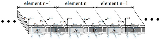
Figure 1.
Schematics of the periodic sandwich plate with elastic boundary conditions.
The two opposite sides of the periodic sandwich plate shown in Figure 1 are in elastic boundary conditions, constrained by four sets of springs. As shown in Figure 2, the tangential, vertical, and transverse vibration displacements of the structure are constrained by three sets of linear springs, and the spring stiffnesses per unit length are denoted as (N/m2), (N/m2), and (N/m2), respectively. In addition, the rotational displacement is constrained by one set of torsional springs, with the spring stiffness per unit length denoted as (N). In order to make it more straightforward to understand the various spring stiffness parameters, a notation table is given in Table 1 for quick reference.
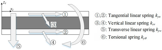
Figure 2.
Schematics and notations of the elastic boundary condition.

Table 1.
The notations of various spring stiffness parameters.
To obtain the vibration calculation formula of the finite or infinite periodic sandwich plate, the governing equations of a uniform sandwich panel, as shown in Figure 3, are first considered. The coordinates and notations of the generalized displacements and forces in the structure are illustrated in the figure to facilitate a better understanding of the basic theory. The length, width, and thickness are denoted as , , and , respectively. The in-plane and transverse displacements are denoted as , , and , and the viscoelastic core’s rotations with respect to axis y and axis x are denoted as and , respectively. The vertical forces of the ith layer are denoted as and , and the tangential forces of the ith layer are denoted as and . The bending moments and shearing forces of the sandwich panel are denoted as , , , and .
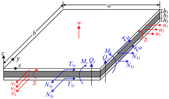
Figure 3.
Coordinates and notations of the generalized displacements and forces in a sandwich plate.
The two surface layers are made of elastic material, while the core layer is made of viscoelastic material. Several models have been established to estimate the damping properties of viscoelastic materials, among which the most commonly used include the Kelvin-Voigt model [47,48], the Maxwell model [49], and the generalized Maxwell model [50]. The Kelvin–Voigt model consists of an elastic spring and a viscous damper connected in parallel, and is suitable for describing delayed strain under constant stress. The Maxwell model is represented by an elastic spring and a viscous damper connected in series, which can be used to describe stress relaxation. The generalized Maxwell model, also known as the Maxwell–Wiechert model, is assembled by multiple Maxwell elements connected in parallel and can be used to assess most of the realistic stress relaxation and frequency-dependent behavior.
Compared to the surface layer, the core layer typically has a significantly smaller modulus. Thus, the shearing effect is considered, and the normal deformation is neglected to simplify the theoretical model. Therefore, the strain energy and kinematic energy of each layer () can be expressed as
and
where , , , , , , and . In Equations (1) and (2), , , , , where , , , and are the Young’s modulus, shear modulus, density, and Poisson’s ratio of each layer, respectively. For modeling convenience purposes, the core’s viscosity is considered in terms of complex modulus with , where is the storage modulus and is the damping loss factor, representing the ratio of the loss modulus to the storage modulus. This damping representation method is similar to the Kelvin-Voigt model, where is equivalent to , with indicating the retardation time in the Kelvin-Voigt model [51,52].
By using Hamilton’s principle, the equations of motion for the homogeneous sandwich panel given in Figure 3 can be given as
where can be obtained in the theoretical derivation process and are given in detail in Equations (A1)–(A14) in Appendix A. The generalized forces at the cross sections of can be expressed as
and those at the cross sections of can be expressed as
2.2. Forced Response
A finite periodic sandwich plate with I + 1 sub sandwich panels in elastic boundary conditions is shown in Figure 4 for forced response calculation purposes. The sub sandwich panels consist of repeated cores A and B, and a harmonic force is applied at sub sandwich panel 0.
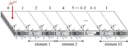
Figure 4.
A finite periodic sandwich plate.
To represent the displacements of the periodic sandwich plate, a complex admissible function of displacements is used in the paper by extending the admissible displacement function proposed by Li et al. [46] for a single-layer thin plate. The in-plane and transverse displacements of the ith sub sandwich plate can be expressed as
where the first part of each displacement function is the main component that contributes to the displacement, and the second part is a supplementary component that addresses the discontinuities of the derivatives at the plate’s edges. In Equation (6), and . The terms , , , , , , , , , , , , , , and are unknown variables, which can be determined by calculating governing differential equations and boundary equations. The admissible function of displacements listed in Equation (6) can be used to satisfy various boundary conditions, including but not limited to free, clamped, simply supported, slipping, continuous, periodic, and elastic boundary conditions. The terms , , , and in Equation (6) can be chosen as
and
where , represents or , and s represents or .
The first- to fourth-order derivatives of can be derived as
where , , , , and .
For derivation convenience, can be expanded in cosine series form as
where is given as
Substituting Equation (10) into Equation (9) gives
where () can be given as , , , , in which .
Substituting Equation (12) into Equation (8) gives
where .
Following the above basic theoretical derivation of the admissible displacement function, the boundary equations of the periodic sandwich plate were examined. As shown in Figure 5, there are three types of boundary conditions, including elastic boundary conditions (EBC) at and , free boundary conditions (FBC) at and , and continuous boundary conditions (CBC) at the connection of two neighboring sub-sandwich panels.
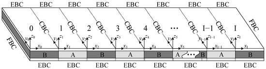
Figure 5.
Boundary conditions in a finite periodic sandwich plate.
2.2.1. EBC of the Finite Periodic Sandwich Plate
At positions and , each sub sandwich panel is constrained by linear and torsional elastic springs. Thus, the boundary equations can be expressed as
2.2.2. FBC of the Finite Periodic Sandwich Plate
At the left end of sub sandwich panel #0 and right end of sub sandwich panel #I, the structure is in free boundary conditions, the corresponding generalized forces should be zero at positions and , which gives
2.2.3. CBC of the Finite Periodic Sandwich Plate
At the interface between two neighboring sub sandwich panels, both the generalized displacements and generalized forces satisfy the continuous condition. Thus, at position (), the boundary equations can be given as
Substituting Equations (4)–(6) into Equations (14)–(16), the boundary equations in matrix form can be given as
where , , and the x-wise and y-wise infinite series are truncated to and , respectively. In the above expression, , , = [, , …, , , …, ] and =[, , …, , ,…, ]. The vectors , , , , , , , and can be arranged similarly to and , except that has elements and has elements. The vector can be given as = [, , …, , , , …, , …, , …, , , …, ]. The vectors , , , and can be arranged similarly to .
It can be easily deduced from Equation (17) that
From boundary equations, Equation (18) is obtained, where the vector is represented by the vector . Next, we will go on to the governing differential equations.
In the derivation, the vibration is assumed in harmonic form. At position on the ith sub sandwich panel, a harmonic point force in the form of is applied. It can be obtained from Equation (3) that the ith sub sandwich panel’s governing differential equation can be given as
where is the force amplitude, and is the Dirac delta function. By multiplying at both sides of the above equation, integrating over the area of , and using the orthogonality of trigonometric functions, the vibration governing equations in detail can be given by Equations (A21)–(A25) in Appendix A. By truncating the x-wise and y-wise infinite series to and and combining all the sub sandwich panels’ governing equations (Equations (A21)–(A25)), the matrix form of all the governing equations can be given as
where , = [, ,…, , , ,…, ,…, , ,…, ]. The force element is expressed as , where and .
By substituting Equation (18) into Equation (20), the vector can be eliminated. Thus, Equation (20) can finally be given by
where and .
When the external point force and frequency are given, the coefficient vector can be obtained by solving Equation (21), and then the coefficient vector can be determined by Equation (18). With vectors and , the in-plane displacements , , , and the transverse displacement of each sub-sandwich panel can be finally analytically acquired from Equation (6).
2.3. Band Structure
The band structure of periodic structures can be determined by both and approaches [53,54]. The approach determines the frequency with given real-valued wave vectors, which can be used to examine the propagating waves. The limitation of this approach is that it is unable to investigate evanescent waves [42,44]. The approach determines the complex wave vectors with given real-valued frequencies, which can be used to examine both propagating waves and evanescent waves. However, due to the complexity of the approach for the periodic sandwich plates with elastic boundary conditions, it is quite complicated to solve the vibration governing equations for given wave vectors. As the focus of this research is the effect of the boundary condition on the band structure, the approach is used in this research for calculation convenience. Thus, the damping effect on the imaginary part of the wave vector cannot be fully covered by this method. Establishing a new model by using approach to obtain the complex band structure is valuable and worth doing in the future.
Using Bloch–Floquet periodic boundary conditions, the vibration characteristics of the infinite periodic sandwich plate can be represented by a vibration model of a unit element. The model of a unit element is shown in Figure 6, where three types of boundary conditions are used: elastic boundary conditions (EBC) at and , periodic boundary conditions (PBC) at and , and continuous boundary conditions (CBC) at the connection of two neighboring sub sandwich panels.
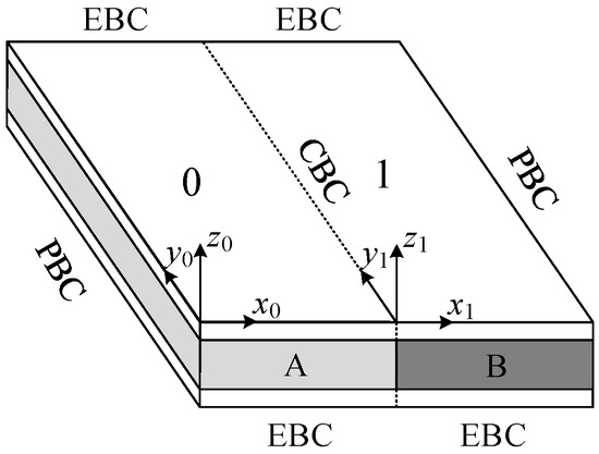
Figure 6.
The periodic sandwich plate’s unit element with periodic boundary conditions (PBC) applied to the left-end boundary () and the right-end boundary ().
2.3.1. EBC of the Single Element
At positions and , each sub sandwich panel is constrained by linear and torsional elastic springs. Thus, the boundary equations can be expressed as
2.3.2. PBC of the Single Element
At the left end of sub sandwich panel #0 and the right end of sub sandwich panel #1, the structure is in Bloch–Floquet periodic boundary conditions, and the corresponding boundary equations can be expressed as
where is the Bloch wavenumber and is the element length.
2.3.3. CBC of the Single Element
At the interface between the two neighboring sub sandwich panels, both the generalized displacements and generalized forces satisfy the continuous condition. Thus, at the position , the boundary equations can be given as
Substituting Equations (4)–(6) into Equations (22)–(24), the combined boundary equations matrix form can be given as
where and . Multiplying at both sides of Equation (30) gives
From boundary equations, Equation (26) is obtained, where the vector is represented by the vector .
After the boundary equations are obtained, following the same calculation procedure shown in Section 2.2, the combined governing equation in matrix form can also be obtained by eliminating the force term , which gives that
Substituting Equation (26) into Equation (27), the vector can be eliminated. Thus, Equation (27) can finally be given by
where and .
By solving Equation (28), a series of characteristic frequencies will be obtained as a function of the wavenumber . Suppose the normalized wavenumber is swept from −1 to +1 in one period. In that case, the wavenumber-dependent dispersion curves of the periodic sandwich plate can be determined, which then gives rise to the band-gap properties of the periodic sandwich plate with elastic boundary conditions.
3. Results and Discussion
3.1. Illustrative Example and Validation
In the illustrated example, the dimensions of a unit element are given as follows. The width of the element is set as 0.35 m, and the lengths of sub-cells A and B are set as 0.125 m and 0.125 m, respectively. The thicknesses of the top, core, and bottom layers are set as 1.8 mm, 5 mm, and 2.0 mm, respectively. Both the top and bottom layers are made of aluminum, with Young’s modulus of 77.6 GPa, shear modulus of 28.7 GPa, Poisson’s ratio of 0.35, and density of 2730 kg/m3. The soft core A is made of polyurethane foam [55] with Young’s modulus 0.138 MPa, shear modulus 0.0511 MPa, Poisson’s ratio 0.35, and density 332 kg/m3. The hard core B is made of thermoplastic rubber with Young’s modulus 250 MPa, shear modulus 83.9 MPa, Poisson’s ratio 0.49, and density 1100 kg/m3.
The boundaries along the x-axis are supported by a set of torsional springs with stiffness (N) per unit length and three sets of linear springs with stiffnesses (N/m2), (N/m2), and (N/m2) per unit length. By setting appropriate stiffness constants, the free boundary conditions (FBC), clamped boundary conditions (CLBC), and simply supported boundary conditions (SBC) can be realized by using specific stiffness values of , , , and , as shown in Table 2.
Table 2.
The various boundary conditions represented by specific stiffness constants.
In the numerical calculation, the infinite stiffness value cannot be defined. In fact, a considerable value can be used to represent infinity. For the material and geometric parameters used in this paper, a value of 1014 for , , , and is big enough to be considered as infinite stiffness. To examine the effect of boundary conditions on vibration characteristics of the periodic sandwich plate and validate the accuracy of the present theory, four cases with FBC, CLBC, SBC, and general EBC are conducted. For the general EBC case, the spring stiffness constants are set as , , , and .
In order to validate the accuracy of the present theoretical model, an FEM model is also established using the commercial FEM software of COMSOL Multiphysics (Version 6.2). Shown in Figure 7 is the mesh schematic diagram of a single-cell FEM model. A quadratic element type is used to simulate. The element size in the horizontal plane is 0.01 m, and there are three layers of meshes in the vertical direction. The total number of meshes is 2730, and the mesh resolution is adequate for the simulation from 0 Hz to 650 Hz. A Floquet periodic condition is applied on the left and right ends of the structure model. By parametrically setting the Floquet wave number and conducting characteristic frequency analysis, the band structure can then be acquired from the FEM model.
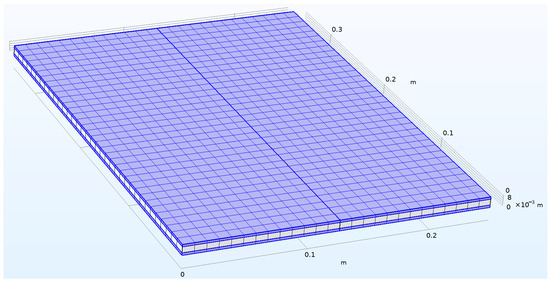
Figure 7.
The mesh schematic diagram of a single-cell FEM model.
The dispersion curves and band gaps of the infinite periodic sandwich plate with an FBC, CLBC, SBC, and general EBC are, respectively, shown in Figure 8, where the results calculated from the present theory are compared to those from FEM.
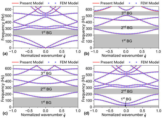
Figure 8.
Band structures of a periodic sandwich plate in (a) free boundary condition, (b) clamped boundary condition, (c) simply supported boundary condition, and (d) elastic boundary condition with , , , and .
As shown in Figure 8d, the dispersion curves and band gaps calculated by the present theory match very well with the results from the FEM model, which validates the accuracy of the present theory. In addition, as shown in Figure 8a–c, the results calculated by the present theory also coincide with the FEM results, which show that the elastic-boundary theoretical model given in this paper has excellent compatibility, where the FBC, CLBC, and SBC can all be included. It is also observed that, unlike the FBC, the first band gap of the CLBC, SBC, and EBC starts from 0 Hz. The wave attenuation in the frequency range of the 1st BG in Figure 8b–d is caused by the boundary restriction. The stronger the boundary restriction is, the broader the band gap width will be. For a non-restricted boundary, as shown in Figure 8a for FBC, the wave will freely propagate without attenuation from 0 Hz. This phenomenon is also observed and discussed in other corresponding studies [10,11].
Under general elastic boundary conditions, the band gaps are subsequently 0 Hz–31.5 Hz and 203.8 Hz–288.3 Hz. In order to further understand the band gap formation of the periodic sandwich plate, the mode shapes of three specific points are given in Figure 9, including the cases of , , and . As shown in Figure 8d and Figure 9a, the first band gap is constituted by a single dispersion branch where three modes exist in the y-axis direction. And the second band gap, as shown in Figure 8d and Figure 9b,c, is constituted by two dispersion branches, where two modes exist in the lower branch in the y-axis direction and no mode exists (plane-wave propagation mode) in the upper branch in the y-axis direction.
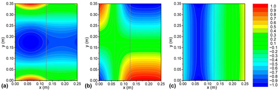
Figure 9.
Mode shapes of the periodic sandwich plate in elastic boundary conditions (, , , and ). (a) ; (b) ; (c) .
While verifying the band structure of the infinite periodic model in this research, the validity of the forced vibration response of the finite periodic structure is also verified. The schematic diagram of the finite periodic model is shown in Figure 4, where the number of unit cells is set to five, resulting in a total of eleven sub-plates. A unit harmonic point force excitation is applied at and of the first sub-plate. The mesh schematic diagram of the finite periodic sandwich plate FEM model is shown in Figure 10. A quadratic element type is used to describe the FEM element. The element size in the horizontal plane is 0.01 m, and there are three layers of meshes in the vertical direction. The total number of meshes is 15,015, and the mesh resolution is adequate for estimating vibration from 0 Hz to 650 Hz.
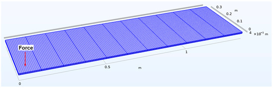
Figure 10.
The mesh schematic diagram of a finite periodic sandwich plate FEM model.
The average vibration velocity of the first () and last () plates and the vibration transmission () from the first to the last plate of the periodic sandwich plate are used to assess the vibration performance. They are defined as , , and , where and are the observation points number selected at the first and the last plate, respectively. The terms and represent the vibration velocity of the ith observation point at the first and the last plate, respectively. Figure 11, Figure 12, Figure 13 and Figure 14 show, respectively, the results of periodic structures under free, clamped, simply supported, and elastic boundary conditions. As shown in the figures, the results calculated using the analytical model in this study align well with those obtained using the finite element model, validating the effectiveness of the proposed model in estimating the vibration transmission characteristics of finite periodic sandwich plates.
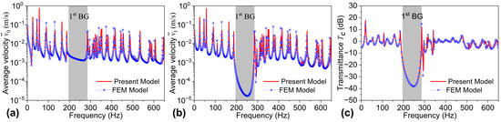
Figure 11.
Spatially averaged velocity of the (a) first cell and (b) last cell, and (c) the transmittance from the first cell to the last cell in a periodic sandwich plate in FBC.
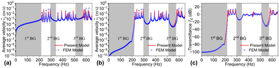
Figure 12.
Spatially averaged velocity of the (a) first cell and (b) last cell, and (c) the transmittance from the first cell to the last cell in a periodic sandwich plate in CLBC.
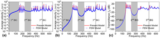
Figure 13.
Spatially averaged velocity of the (a) first cell and (b) last cell, and (c) the transmittance from the first cell to the last cell in a periodic sandwich plate in SSBC.
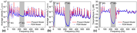
Figure 14.
Spatially averaged velocity of the (a) first cell and (b) last cell, and (c) the transmittance from the first cell to the last cell in a periodic sandwich plate in EBC.
In addition, the gray areas in Figure 11, Figure 12, Figure 13 and Figure 14 represent the band gaps calculated from an infinite periodic sandwich plate. By comparing with Figure 8, it can be seen that the response valley frequency regions of the finite periodic structure calculated theoretically match well with the band gap frequency ranges calculated from the infinite periodic structure, thereby verifying, to some extent, the validity of the analytical model presented in Section 2.2. Shown in Figure 15 are the vibration displacement distributions of the periodic sandwich plate in an elastic boundary condition with different frequencies. Figure 15a,b illustrate the vibration transmission characteristic of the waves in band gaps, with the frequency taken as 25 Hz in the first band gap and 250 Hz in the second band gap, respectively. In these two subfigures, it can be observed that the waves cannot propagate freely from the left end to the right end, and the vibration energy is mostly restricted near the excitation position. Figure 15c,d illustrate the vibration transmission characteristics of the waves outside band gaps, with the frequency taken as 107 Hz and 421 Hz, respectively. It can be observed from these two subfigures that, unlike in the band gap, waves outside the band gap can propagate freely from the left end to the right end, and the vibration energy can distribute throughout the structure.
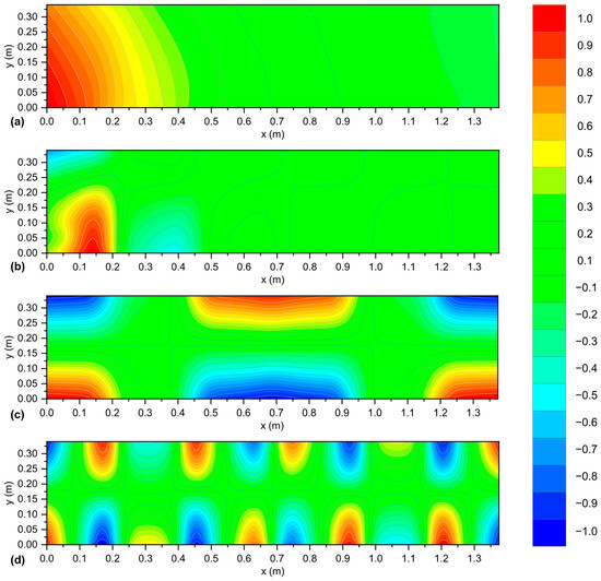
Figure 15.
Vibration displacement distributions of the periodic sandwich plate in elastic boundary conditions (, , , and ). (a) In the first band gap: ; (b) In the second band gap: ; (c) Outside the band gap: ; (d) Outside the band gap: .
3.2. Parametric Analysis
From Figure 11, Figure 12, Figure 13 and Figure 14, it can be observed that the bending-wave band structure and band-gap characteristics of the periodic sandwich plate are related to the boundary conditions on both sides. For example, under free boundary conditions, the band gap is 195.3 Hz–285.9 Hz; under clamped boundary conditions, the band gaps are subsequently 0 Hz–217.8 Hz, 294.8 Hz–342.9 Hz, and 508.1 Hz–574.2 Hz; under simply supported boundary conditions, the band gaps are subsequently 0 Hz–151.4 Hz, 231.9 Hz–327.8 Hz, and 491.2 Hz–502.3 Hz; and under general elastic boundary conditions, the band gaps are subsequently 0 Hz–31.5 Hz and 203.8 Hz–288.3 Hz. The results clearly demonstrate that different boundaries produce distinct band gaps, and boundary conditions have a significant impact on the band-gap frequency ranges.
Assuming all four spring stiffnesses have identical values, namely . For simplicity, we use to denote these four equal stiffness values. Here, represents only a numerical value without indicating units. When takes specific values, the units of , , and are set to be N/m2, and that of is set to be N.
Figure 16 shows the influence of varying the boundary spring stiffness synchronously on the band gap frequency range and bandwidth when the four spring stiffnesses (, , , and ) change simultaneously. As shown, with increasing , the band gap frequencies gradually increase, and the total bandwidth within the 0 Hz–650 Hz frequency range also increases successively from 92.4 Hz to 337.4 Hz. Thus, increasing the boundary spring stiffness contributes to achieving broader band gaps. Figure 17 presents the vibration transmissions from the first plate to the last plate when takes various values. It can be seen from the figure that the band gap variations caused by eventually affect the vibration transmission characteristics across the finite periodic sandwich plate structure, with different boundaries corresponding to different transmission valley regions.
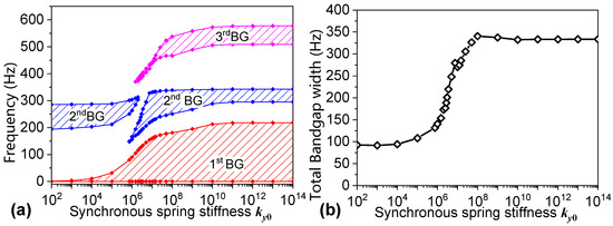
Figure 16.
(a) Band structures and (b) Total bandgap width as a function of stiffness . ().
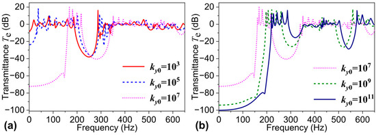
Figure 17.
Transmittances from the first cell to last cell in the periodic sandwich plate with various spring stiffnesses: (a) ky0 = 103, 105, 107 and (b) ky0 = 107, 109, 1011.
Figure 18, Figure 19, Figure 20 and Figure 21, respectively, show the effects on the band gap frequency range when the tangential spring stiffness , vertical spring stiffness , transverse spring stiffness , or torsional spring stiffness changes individually. When evaluating the effect of one particular spring stiffness on the band-gap characteristics, the other three spring stiffnesses are set to zero.
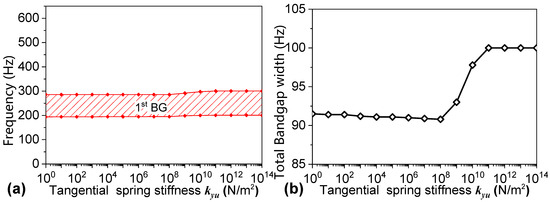
Figure 18.
(a) Band structures and (b) Total bandgap width as a function of tangential linear spring stiffness kyu.
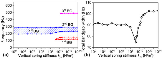
Figure 19.
(a) Band structures and (b) Total bandgap width as a function of transverse linear spring stiffness kyv.
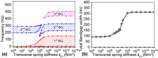
Figure 20.
(a) Band structures and (b) Total bandgap width as a function of transverse linear spring stiffness kyw.
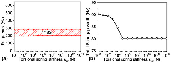
Figure 21.
(a) Band structures and (b) Total bandgap width as a function of torsional spring stiffness .
Figure 18, Figure 19 and Figure 21 show that the tangential spring stiffness , vertical spring stiffness , and torsional spring stiffness have relatively minor impacts on the band gap frequency range, with the maximum frequency variation less than 10 Hz. However, as shown in Figure 20, the transverse spring stiffness has a significant effect on the band gap frequency range. With increasing , both the band gap frequency and the bandwidth gradually increase. Similarly to the effect of total spring stiffness shown in Figure 16, increasing also noticeably increases the bandwidth.
Figure 22 presents a comparison of the total band gap widths within the 0 Hz–650 Hz frequency range when , , , and vary separately and when all four types of spring stiffness vary simultaneously (represented by ).
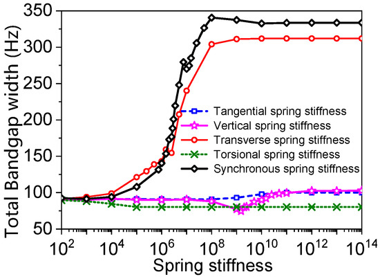
Figure 22.
Total bandgap widths as a function of various spring stiffnesses.
By comparing the five curves in Figure 22, it can be concluded that the tangential spring stiffness , vertical spring stiffness , and torsional spring stiffness have minor effects on the total bandwidth. In contrast, the transverse spring stiffness has a considerable impact on the total bandwidth. This phenomenon can be physically explained by referring to Equation (14), where these four different spring stiffnesses are included. As shown in Figure 8d and Figure 9, the first two band gaps of the periodic sandwich plate are related to transverse-wave propagation modes, which are dominated by the transverse displacement instead of the in-plane or torsional displacement. As shown in Equation (14), the transverse spring stiffness directly restricts the transverse displacement , whereas the tangential spring stiffness , vertical spring stiffness , and torsional spring stiffness indirectly affect the transverse displacement by restricting the in-plane displacements and and torsional displacement . Therefore, changing the transverse spring stiffness is more effective for adjusting the band-gap width.
4. Conclusions
Based on the theory of elastic dynamics and Hamilton’s principle, this research obtains the dynamic control equations of a uniform sandwich plate. On this basis, the transfer matrix method is employed to develop a theoretical model for calculating the band structure and vibration response of periodic sandwich plates under elastic boundary conditions. At the same time, the finite element method is used to verify the model, and the effect of boundary conditions on the variation in band-gap characteristics is obtained through parameter analysis.
Due to the Bragg scattering effect, the periodic sandwich plate exhibits good band-gap characteristics, and the vibration transmission shows strong attenuation characteristics within the band gap, which can be used in vibration and noise reduction designs. The change in boundary conditions has a significant effect on the band-gap characteristics of the periodic sandwich plate, and different boundary conditions correspond to different band-gap characteristics. When the stiffness of each spring changes synchronously, increasing the spring stiffness can shift the band-gap frequency to a higher frequency, and the total band-gap width gradually increases. At this time, enhancing the boundary constraint can improve the band-gap characteristics to a certain extent. Further research indicates that the transverse spring stiffness controlling the transverse displacement at the boundary plays a significant role in altering the band gap, making it more effective for adjusting the band-gap width in the vibration reduction design process.
The sandwich structure with periodic cores studied in this research can be used as a base plate on which the vibration equipment is mounted. The base plate is commonly used in ships or large-scale underwater vehicles. By properly designing the material and geometrical parameters and carefully tuning the structure’s boundary, it is promising to locate the vibration equipment’s working frequency in the band-gap frequency range, thereby reducing the vibration transmittance.
This work is limited to the sandwich-plate structure with periodic cores, which can be further extended to composite or laminate structures. The corresponding extended research may provide more helpful guidance on vibration control in practical engineering. In addition, this work is limited to the approach in the band structure estimation, where the complex band structure cannot be acquired. Establishing a new model by using the approach to obtain the complex band structure is valuable and worth doing in the future.
Author Contributions
Conceptualization, Z.G. and M.S.; methodology, Z.G. and M.S.; software, Z.G.; validation, Z.G.; formal analysis, Z.G. and M.S.; investigation, Z.G.; resources, M.S.; data curation, K.Z.; writing—original draft preparation, Z.G.; writing—review and editing, M.S.; visualization, K.Z.; supervision, M.S.; project administration, M.S.; funding acquisition, Z.G. All authors have read and agreed to the published version of the manuscript.
Funding
This research was funded by the National Natural Science Foundation of China (52301388).
Institutional Review Board Statement
Not applicable.
Informed Consent Statement
Not applicable.
Data Availability Statement
The original contributions presented in this study are included in the article. Further inquiries can be directed to the corresponding author.
Conflicts of Interest
The authors declare no conflicts of interest.
Appendix A
The differential operators in Equation (3) can be expressed as
and
where , , , , , and .
The matrices to used in Equation (9) can be expressed as
and
The term in Equation (10) can be expressed as
The vibration governing equations of the finite periodic sandwich plate can be expressed as
and
where , (The terms s and t represent the corresponding numbers that exist in (Equations (A21)–(A25)) is the coefficient which can be determined from the above derivation and is independent of the variables to be determined.
References
- Mead, D.J. Wave propagation in continuous periodic structures: Research contributions from Southampton, 1964–1995. J. Sound. Vib. 1996, 190, 495–524. [Google Scholar] [CrossRef]
- Gupta, G.S. Vibration of Periodic Structures; Elsevier: Amsterdam, The Netherlands, 2024. [Google Scholar]
- Vasileiadis, T.; Varghese, J.; Babacic, V.; Gomis-Bresco, J.; Urrios, D.N.; Graczykowski, B. Progress and perspectives on phononic crystals. J. Appl. Phys. 2021, 129, 160901. [Google Scholar] [CrossRef]
- Huang, W.; Xu, J.; Yao, Y.; Zhang, Y.; Wang, X.; Han, P. Application of phononic crystals in modern engineering vibration and noise control, a review. Noise Vib. Worldw. 2025, 56, 224–241. [Google Scholar] [CrossRef]
- Aydin, G.; San, S.E. Breaking the limits of acoustic science: A review of acoustic metamaterials. Mat. Sci. Eng. B-Adv. 2024, 305, 117384. [Google Scholar] [CrossRef]
- Brillouin, L. Wave Propagation in Periodic Structures; Dover Publications Inc: New York, NY, USA, 1953. [Google Scholar]
- Narayanamurti, V.; Störmer, H.L.; Chin, M.A.; Gossard, A.C.; Wiegmann, W. Selective transmission of high-frequency phonons by a superlattice: The “dielectric” phonon filter. Phys. Rev. Lett. 1979, 43, 2012. [Google Scholar] [CrossRef]
- Kushwaha, M.S.; Halevi, P.; Dobrzynski, L.; Djafari-Rouhani, B. Acoustic band structure of periodic elastic composites. Phys. Rev. Lett. 1993, 71, 2022. [Google Scholar] [CrossRef]
- Gao, F.C.; Wu, Z.J.; Li, F.M.; Zhang, C.Z. Numerical and experimental analysis of the vibration and band-gap properties of elastic beams with periodically variable cross sections. Wave Random Complex. 2019, 29, 299–316. [Google Scholar] [CrossRef]
- Yu, D.L.; Wen, J.H.; Shen, H.J.; Xiao, Y.; Wen, X.S. Propagation of flexural wave in periodic beam on elastic foundations. Phys. Lett. A 2012, 376, 626–630. [Google Scholar] [CrossRef]
- Ding, L.; Ye, Z.; Wu, Q. Flexural vibration band gaps in periodic Timoshenko beams with oscillators in series resting on flexible supports. Adv. Struct. Eng. 2020, 23, 3117–3127. [Google Scholar] [CrossRef]
- Han, Y.R.; Chen, X.H.; Wei, Y.H.; Jiang, S.; Du, C.; Jiang, G.Q.; Zhang, H. Vibration attenuation of metamaterial dual-beam with simultaneous acoustic black hole and local resonator. Eur. J. Mech. A-Solid. 2025, 111, 105535. [Google Scholar] [CrossRef]
- Chen, J.; Chao, I.; Chen, T. Bandgaps for flexural waves in infinite beams and plates with a periodic array of resonators. J. Mech. 2022, 38, 376–389. [Google Scholar] [CrossRef]
- Wang, K.; Zhou, J.X.; Cai, C.Q.; Xu, D.L.; Ouyang, H.J. Mathematical modeling and analysis of a meta-plate for very low-frequency band gap. Appl. Math. Model. 2019, 73, 581–597. [Google Scholar] [CrossRef]
- Wang, Q.; Li, J.Q.; Zhang, Y.; Xue, Y.; Li, F.M. Bandgap properties in metamaterial sandwich plate with periodically embedded plate-type resonators. Mech. Syst. Signal Process 2021, 151, 107375. [Google Scholar] [CrossRef]
- Miao, Z.; Yin, J.; Yang, Y.; Ke, Y.; Zheng, Z.; Geng, X.; Wang, Q. Design of multi-bandgap metamaterial plate based on composite cylindrical resonators. Mater. Des. 2025, 250, 113570. [Google Scholar] [CrossRef]
- Russillo, A.F.; Failla, G.; Alotta, G. Ultra-wide low-frequency band gap in locally-resonant plates with tunable inerter-based resonators. Appl. Math. Model. 2022, 106, 682–695. [Google Scholar] [CrossRef]
- Heckl, M.A. Coupled waves on a periodically supported Timoshenko beam. J. Sound. Vib. 2002, 252, 849–882. [Google Scholar] [CrossRef]
- Cremer, L.; Leilich, H.O. On theory of flexural periodic systems. Arch. Elektr. Ubertragung 1953, 7, 261–270. [Google Scholar]
- Langley, R.S.; Smith, J.R.D.; Fahy, F.J. Statistical energy analysis of periodically stiffened damped plate structures. J. Sound. Vib. 1997, 208, 407–426. [Google Scholar] [CrossRef]
- Zhang, Z.; Chen, H.; Ye, L. A stiffened plate element model for advanced grid stiffened composite plates/shells. J. Compos. Mater. 2011, 45, 187–202. [Google Scholar] [CrossRef]
- Wen, J.H.; Yu, D.L.; Wang, G.; Zhao, H.G.; Liu, Y.Z. Elastic wave band gaps in flexural vibrations of straight beams. J. Mech. Eng. 2015, 41, 1–6. [Google Scholar] [CrossRef]
- Liu, S.; Li, S.; Shu, H.; Wang, W.; Shi, D.; Dong, L.; Lin, H.; Liu, W. Research on the elastic wave band gaps of curved beam of phononic crystals. Phys. B 2015, 457, 82–91. [Google Scholar] [CrossRef]
- Fang, J.; Yu, D.; Han, X.; Cai, L. Coupled flexural-torsional vibration band gap in periodic beam including warping effect. Chin. Phys. B 2009, 18, 1316. [Google Scholar] [CrossRef]
- Cenedese, M.; Belloni, E.; Braghin, F. Interaction of Bragg scattering bandgaps and local resonators in mono-coupled periodic structures. J. Appl. Phys. 2021, 129, 124501. [Google Scholar] [CrossRef]
- Sorokin, S.V.; Ershova, O.A. Plane wave propagation and frequency band gaps in periodic plates and cylindrical shells with and without heavy fluid loading. J. Sound. Vib. 2004, 278, 501–526. [Google Scholar] [CrossRef]
- Zhang, J. Band gap attenuation characteristics of periodic compound plate with wave propagation approach. Acta Phys. Sin-Ch Ed. 2014, 63, 224302. [Google Scholar] [CrossRef]
- Wu, Z.; Li, F.; Wang, Y. Study on vibration characteristics in periodic plate structures using the spectral element method. Acta Mech. 2013, 224, 1089–1101. [Google Scholar] [CrossRef]
- Guo, Z.W.; Sheng, M.P.; Pan, J. Effect of boundary conditions on the band-gap properties of flexural waves in a periodic compound plate. J. Sound. Vib. 2017, 395, 102–126. [Google Scholar] [CrossRef]
- Guo, Z.; Sheng, M.; Zeng, H. Vibration attenuation in a beam structure with a periodic free-layer damping treatment. Machines 2023, 11, 949. [Google Scholar] [CrossRef]
- Ruzzene, M.; Mazzarella, L.; Tsopelas, P.; Scarpa, F. Wave propagation in sandwich plates with periodic auxetic core. J. Intell. Mater. Syst. Struct. 2002, 13, 587–597. [Google Scholar] [CrossRef]
- Ruzzene, M.; Tsopelas, P. Control of wave propagation in sandwich plate rows with periodic honeycomb core. J. Eng. Mech-ASCE 2003, 129, 975–986. [Google Scholar] [CrossRef]
- Sheng, M.P.; Guo, Z.W.; Qin, Q.; He, Y.A. Vibration characteristics of a sandwich plate with viscoelastic periodic cores. Compos. Struct. 2018, 206, 54–69. [Google Scholar] [CrossRef]
- Jiang, C.; Xiang, Y.; He, P.; He, H. Vibration attenuation behaviors of finite sandwich plates with periodic core. Appl. Acoust. 2020, 157, 107009. [Google Scholar] [CrossRef]
- Robin, G.; Huchard, T.; Poncot, M.; Daya, E.M. Experimental investigation of the periodic core sandwich structure: Shape of the vibration modes. Mech. Res. Commun. 2025, 147, 104434. [Google Scholar] [CrossRef]
- Huchard, T.; Robin, G.; Ponçot, M.; Hoppe, S.; Daya, E.M. Elaboration, characterization and modelling of periodic viscoelastic sandwich beams for lightening and vibration damping. Mech. Res. Commun. 2022, 121, 103863. [Google Scholar] [CrossRef]
- Dou, Y.K.; Zhang, J.G.; Wen, X.L.; Cheng, H.; Liu, H.X. Free vibration characteristics of CFRP laminate with one-dimensional periodic structures. Polymers 2023, 15, 1118. [Google Scholar] [CrossRef]
- E, L.Z.Y.; Chen, Z.Y.; Li, F.M.; Zou, G.P. Band-gap properties of elastic sandwich metamaterial plates with composite periodic rod core. Acta Mech. Solida Sin. 2022, 35, 51–62. [Google Scholar] [CrossRef]
- Zi, H.; Li, Y.G. Low-frequency broadband vibration attenuation of sandwich plate-type metastructures with periodic thin-wall tube cores. J. Low. Freq. Noise V. A 2022, 41, 330–339. [Google Scholar] [CrossRef]
- Shen, C.M.; Huang, J.; Zhang, Z.X.; Xue, J.Y.; Qian, D.H. Sandwich plate structure periodically attached by s-shaped oscillators for low frequency ship vibration isolation. Materials 2023, 16, 2467. [Google Scholar] [CrossRef] [PubMed]
- Li, C.F.; Chen, Z.B.; Jiao, Y.H. Vibration and bandgap behavior of sandwich pyramid lattice core plate with resonant rings. Materials 2023, 16, 2730. [Google Scholar] [CrossRef]
- Zhao, Y.P.; Wei, P.J. The band gap of 1D viscoelastic phononic crystal. Comp. Mater. Sci. 2009, 46, 603–606. [Google Scholar] [CrossRef]
- Chen, Y.F.; Guo, D.; Li, Y.F.; Li, G.Y.; Huang, X.D. Maximizing wave attenuation in viscoelastic phononic crystals by topology optimization. Ultrasonics 2019, 94, 419–429. [Google Scholar] [CrossRef]
- Oliveiraa, V.B.S.d.; Schalcherb, L.F.C.; Santosc, J.M.C.D.; de Miranda, E.J.P., Jr. Wave attenuation in 1-D viscoelastic phononic crystal rods using different polymers. Mat. Res. 2023, 26, e20220534. [Google Scholar] [CrossRef]
- Miranda, E.J.P., Jr.; Dal Poggetto, V.F.; Pugno, N.M.; Dos Santos, J.M.C. Extended plane wave expansion formulation for viscoelastic phononic thin plates. Wave Motion 2023, 123, 103222. [Google Scholar] [CrossRef]
- Li, W.; Zhang, X.; Du, J.; Liu, Z. An exact series solution for the transverse vibration of rectangular plates with general elastic boundary supports. J. Sound. Vib. 2009, 321, 254–269. [Google Scholar] [CrossRef]
- Thomson, W. On the elasticity and viscosity of metals. Proc. R. Soc. Lond. A Math. Phys. Sci. 1865, 14, 289–297. [Google Scholar] [CrossRef]
- Voigt, W. Ieber innere Reibung fester korper, insbesondere der Metalle. Ann. Phys. 1892, 283, 671–693. [Google Scholar] [CrossRef]
- Maxwell, J.C. On the dynamical theory of gases. Philos. Trans. R. Soc. Lond. A 1867, 157, 49–88. [Google Scholar] [CrossRef]
- Wiechert, E. Gesetze der elastischen Nachwirkung für constante Temperatur. Ann. Phys. 1893, 286, 335–348. [Google Scholar] [CrossRef]
- Cremer, L.; Heckl, M.; Petersson, B.A.T. Structure-Borne Sound: Structural Vibrations and Sound Radiation at Audio Frequencies; Springer Science & Business Media: New York, NY, USA, 2013. [Google Scholar]
- Wikipedia. Available online: https://en.wikipedia.org/wiki/Kelvin%E2%80%93Voigt_material (accessed on 3 September 2025).
- Andreassen, E.; Jensen, J.S. Analysis of phononic bandgap structures with dissipation. J. Vib. Acoust. 2013, 135, 041015. [Google Scholar] [CrossRef]
- Nouh, M.A.; Aldraihem, O.J.; Baz, A. Periodic metamaterial plates with smart tunable local resonators. J. Intell. Mater. Syst. Struct. 2015, 27, 1829–1845. [Google Scholar] [CrossRef]
- MatWeb. Available online: https://www.matweb.com/search/DataSheet.aspx?MatGUID=1ebba7628d0247ebbbd062be91dd3cb4&ckck=1 (accessed on 1 September 2025).


Disclaimer/Publisher’s Note: The statements, opinions and data contained in all publications are solely those of the individual author(s) and contributor(s) and not of MDPI and/or the editor(s). MDPI and/or the editor(s) disclaim responsibility for any injury to people or property resulting from any ideas, methods, instructions or products referred to in the content. |
© 2025 by the authors. Licensee MDPI, Basel, Switzerland. This article is an open access article distributed under the terms and conditions of the Creative Commons Attribution (CC BY) license (https://creativecommons.org/licenses/by/4.0/).