Article

Analysis and Evaluation of a Joint Path Planning Algorithm for the Quasi-Spherical Parallel Manipulator, a Master Device for Telesurgery

by
Daniel Pacheco Quiñones
1,*,
Daniela Maffiodo
1 and
Med Amine Laribi
2
1
Department of Mechanical and Aerospace Engineering, Politecnico di Torino, 10129 Turin, Italy
2
Institut PPrime, 86360 Chasseneuil-du-Poitou, France
*
Author to whom correspondence should be addressed.
Machines 2025, 13(9), 858; https://doi.org/10.3390/machines13090858
Submission received: 17 July 2025 / Revised: 31 August 2025 / Accepted: 12 September 2025 / Published: 16 September 2025

Abstract

This work presents the experimental validation of a reset control mode for a Quasi-Spherical Parallel Manipulator (qSPM), designed as a master device for bilaterally teleoperated telesurgical systems. The reset functionality enables autonomous repositioning of the master device to its central configuration via a joint-space path planning algorithm, executed entirely within the local control loop. Given the non-convex nature of the joint space, the algorithm computes feasible trajectories using a simplified optimization scheme that ensures compliance with mechanical and kinematic constraints. The algorithm was implemented within an ROS Noetic framework and tested across multiple scenarios, including both simulated and physical configurations. The experimental results confirm the device’s ability to reset to the central position in approximately 5 s, maintaining an average residual error below 0.25 ° . Computational evaluations demonstrate that each path is generated in less than 10 milliseconds, supporting real-time execution. Additional trials show successful motion toward arbitrary points within the joint space, suggesting the potential for future integration of user-driven repositioning features. These findings highlight the responsiveness, reliability, and experimental feasibility of the proposed control mode, marking a key step toward improving usability in telesurgical environments.

1. Introduction

Bilateral teleoperation (BT) is a control methodology ensuing a constant bidirectional flow of information between a local master device, managed and directly handled by a human operator, and a remote slave device, tasked to interact with an environment where direct human intervention is logistically or physically challenging, impractical, or impossible [1,2,3,4]. The classical application fields for BT range from aerospace and adverse-ground exploration [5,6] to precision handling [7], telemedicine [3,4,8,9,10,11,12], and telesurgery [4,10,11,12].
In a bilaterally teleoperated system (BTS), the bidirectional exchange of data enables the operator to directly perceive and remotely interact with the environment, allowing for telepresence, and enhancing precision and dexterity with situational awareness. However, the performance of BT systems can be significantly affected by factors such as communication delays, transmission errors, and mechanical limitations of the hardware, necessitating the development of advanced control strategies and optimization algorithms [13,14,15] to ensure stability, flexibility [16], stability through robustness [17] or predictiveness [18,19], and security [2,20]. Among the earliest approaches proposed to cope with communication delays is the move-and-wait strategy, which decouples motion commands and force feedback by allowing the master device to send position commands, wait for the slave execution and feedback, and only then resume operation [2,21].
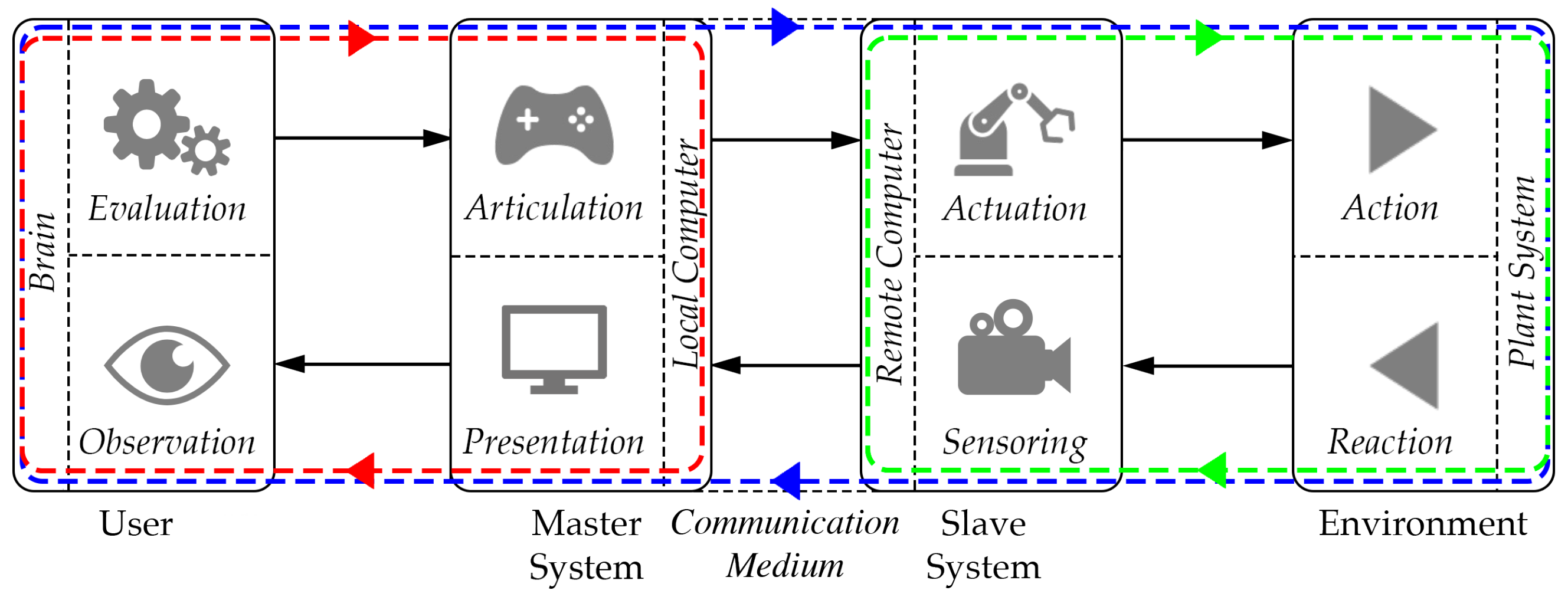
As first theorized by Ferrell and Sheridan [1], BTSs contain three main control loops, as shown in Figure 1:
  • A local control loop (in red in Figure 1): it is closed among the human end user, the master device, and, optionally [7], a local computer. The master system offers the end user feedback through a presentation subsystem. The end user, through the Human–Machine interface (HMi), observes this feedback, evaluates, and then articulates their goal, planning future movements within an environment independent of the remote one. This loop often incorporates a virtual and possibly augmented model of the system, frequently implementing a Digital Twin (DT);
  • A remote control loop (in green in Figure 1): it is closed among the environment, the slave device, and, optionally, a remote computer. In this loop, control procedures required for routines that do not require direct human intervention enable automatic and unsupervised operation of the device, which is able to interact with the environment by means of actuation and sensoring subsystems;
  • A teleoperation control loop (in blue in Figure 1): closed by all the above-mentioned elements, it represents the main loop for BT, enabling user telepresence through Human–Machine Interaction (HMI) with the master device, a bidirectional flow of information strongly dependent on the communication medium, and task execution and feedback from the slave device.
In the field of telesurgical operations, BT is implemented in procedures where the surgeon, physically separated from the operating table, performs movements on the master device, which are translated into commands for a remote slave robot. Through bilateral teleoperation, the system ensures real-time visual, haptic, and auditory feedback, enhancing precision and minimizing the impact of physiological tremors [22]. A slave-teleoperated system is often implemented in minimally invasive surgery (MIS). MIS procedures shorten recovery and hospitalization times, reduce wound complications, and improve scar cosmesis [11,23]. MIS often involves laparoscopic procedures [24,25] adopting a Remote Center of Motion (RCM) rule to minimize surgical incision. The BT architecture also facilitates real-time collaboration and expertise sharing between surgeons located at different medical centers [4,11]. This includes telementoring, in which an expert provides remote guidance throughout the procedure, and teleproctoring, where a mentor actively supervises or assumes partial control over specific surgical steps [3,26,27]. However, telesurgery also presents significant challenges, particularly concerning communication latency, data integrity, system robustness, and patient safety, which have driven extensive research in both hardware design and advanced control strategies [4,11,12].
Several telesurgical robotic platforms have been developed and clinically tested over the years. One of the earliest systems was the ZEUS Robotic Surgical System (Computer Motion, Goleta, CA, USA), which enabled remote laparoscopic procedures and played a foundational role in the evolution of surgical robotics [28,29]. The da Vinci Surgical System (Intuitive Surgical Inc., Sunnyvale, CA, USA) represents the most widely adopted platform worldwide, offering high-precision minimally invasive procedures with sophisticated visualization and motion scaling capabilities [3,4,10,12,30]. The Senhance Surgical Robotic System (Asensus Surgical, Durham, NC, USA) introduces features such as head and eye-tracking camera control to enhance the surgeon’s situational awareness and navigation [31,32]. More recently, the Hugo RAS (Medtronic, Minneapolis, MN, USA) was introduced, providing modularity, portability, and advanced digital integration aimed at expanding access to robotic-assisted surgery across diverse healthcare settings [33].
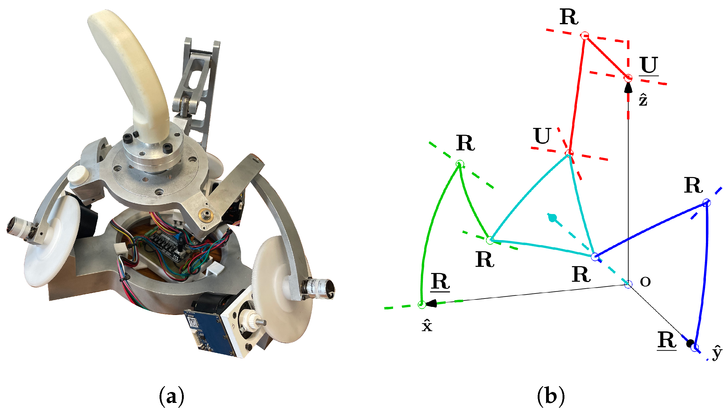
In this context, one of the authors previously proposed various master device architectures for RCM-constrained laparoscopic procedures [34,35], while recent work by the present research team has focused on the modeling, control, and evaluation of a prototype iteration called the Quasi-Spherical Parallel Manipulator (qSPM) [36,37,38,39], as shown in Figure 2. The device’s 1URU-2RRR architecture enables haptic feedback and dexterous maneuvering of the end effector (EE) [36], while various control methodologies have been implemented on both the teleoperation and local control loops [36,37,38]. The spherical parallel architecture shares similarities with other systems present in the literature, such as [40,41].
This paper, conceived as an extended version of [37], focuses on the reset functionality of the device. In this control mode, the system automatically resets the master device to its workspace center r C to facilitate practical and precise coupling with the slave system. Centering the master device provides the surgeon with a neutral and ergonomically favorable starting posture, minimizes the risk of joint limit saturation during prolonged procedures, and ensures optimal correlation between master and slave workspaces, especially after interruptions, handoffs, or re-initializations. A properly implemented reset function could thus reduce intraoperative adjustment time, a challenge that must be faced by the surgeon [42,43].
This paper is organized as follows: Section 2 presents the fundamental kinematics and control principles of the device, introduces the reset mode, describes its integration within the overall control architecture, and outlines the methodologies adopted for performance evaluation. Section 3 and Section 4 present and discuss, respectively, the results obtained from the preliminary testing of the device using these methodologies. The latter section concludes the paper by summarizing the key findings and providing perspectives for future developments.

2. Materials and Methods

2.1. Kinematic Insights

The qSPM’s architecture has been thoroughly revised and presented in [36]. The reachable workspace is greatly affected by the device’s working modes, i.e., the solutions of the inverse kinematics, linking the EE orientation R E Euler z x z triplet P = ( ψ , θ , ϕ ) with the actuated angles Q = ( θ 1 A , θ 1 B , θ 1 C ) , as in Figure 3.
It has been shown in [36] that the optimal working mode is m 3 , in which the RRR legs are widely spread apart and the URU leg is articulated outward, i.e., the one displayed in Figure 3. In fact, said mode shows best results in terms of self-collision and device’s dexterity index η ( J ) :
η ( J ) = d e f 1 κ ( J ) = 1 | | J | | · | | J 1 | | , 0 < η ( J ) < 1
In which J is the Jacobian of the architecture, as presented in [36]; 1 < κ ( J ) < is the condition number of J, denoting the proximity to a singular configuration [44,45].
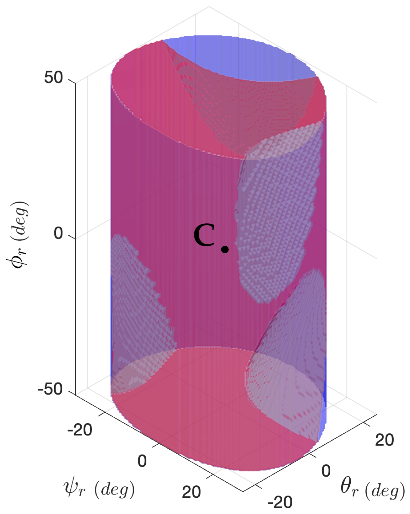
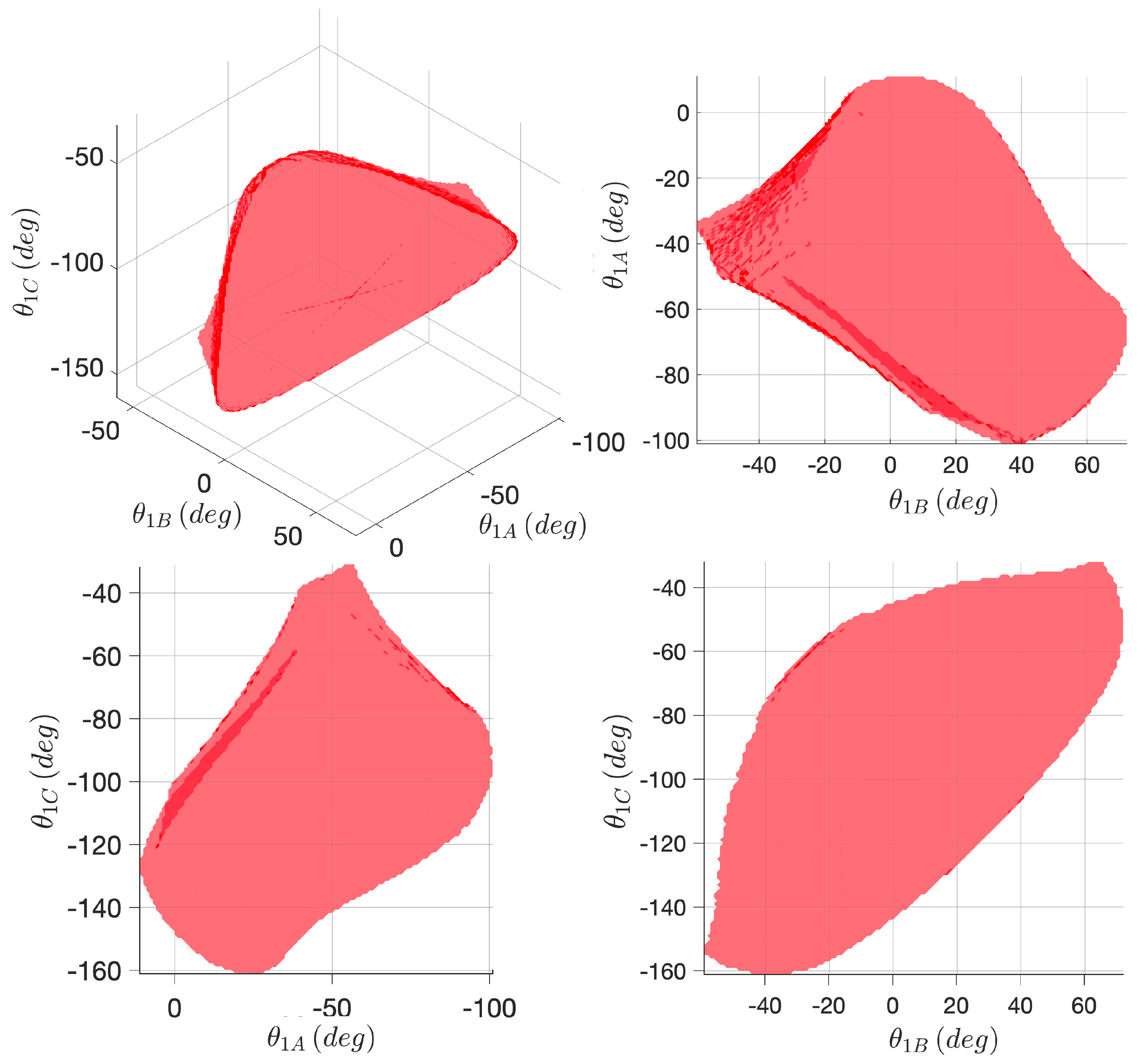
As a consequence, mode m 3 outputs the widest reachable workspace W r e a c h , 3 (2) inside the application workspace W a p p , associated with the restricted aspect A 3 (3) inside the overall joint space W j , as thoroughly described in [36]. Dominions W r e a c h , 3 and A 3 are visually presented, respectively, in Figure 4 and Figure 5.
W r e a c h , 3 = { P W a p p , m 3 s ( C , P ) C 0 : s ( C , P ) ( S J , 3 C V , 3 ) = }
A 3 = def { Q W j | ( P , Q ) m 3 , W reach , 3 ( Q ) A 3 , s ( Q , Q ) C 0 : s ( Q , Q ) A 3 } (3a) (3b)
In which C = ( ψ C ,   θ C ,   ϕ C ) = ( 135.0 ,   54.7 ,   0.0 ) ° are the coordinates of the application workspace center; s ( C , P ) C 0 is a continuous path from C to P ; critical dominions S J , 3 and C V , 3 are points in which, respectively, η ( J ) < η t h r = 0.02 chosen as minimal dexterity before singularity and a self-collision happens; Q , Q is every possible couple of points in A 3 ; i.e., (3b) means A 3 is path-connected; coordinates of P r = ( ψ r ,   θ r ,   ϕ r ) , reported in Figure 4, are relative to workspace center so that P r = P C .

2.2. Control Insights

The device’s control architecture highly depends on the static expression
τ = τ h a p t + τ c o m p + τ c t r l = J t T + τ c o m p + τ c t r l
In which τ h a p t is the feedback haptic torque coming from the slave device and presented to the end user via the actuated angles; τ c o m p is the gravity compensation torque to maintain the unhandled device in equilibrium from gravity; τ c t r l represents extra control torque for operations in the local control loop described in Section 1, as in [36,37,38]; T represents the torque to be sensed directly at the end effector, mirroring the slave device’s.
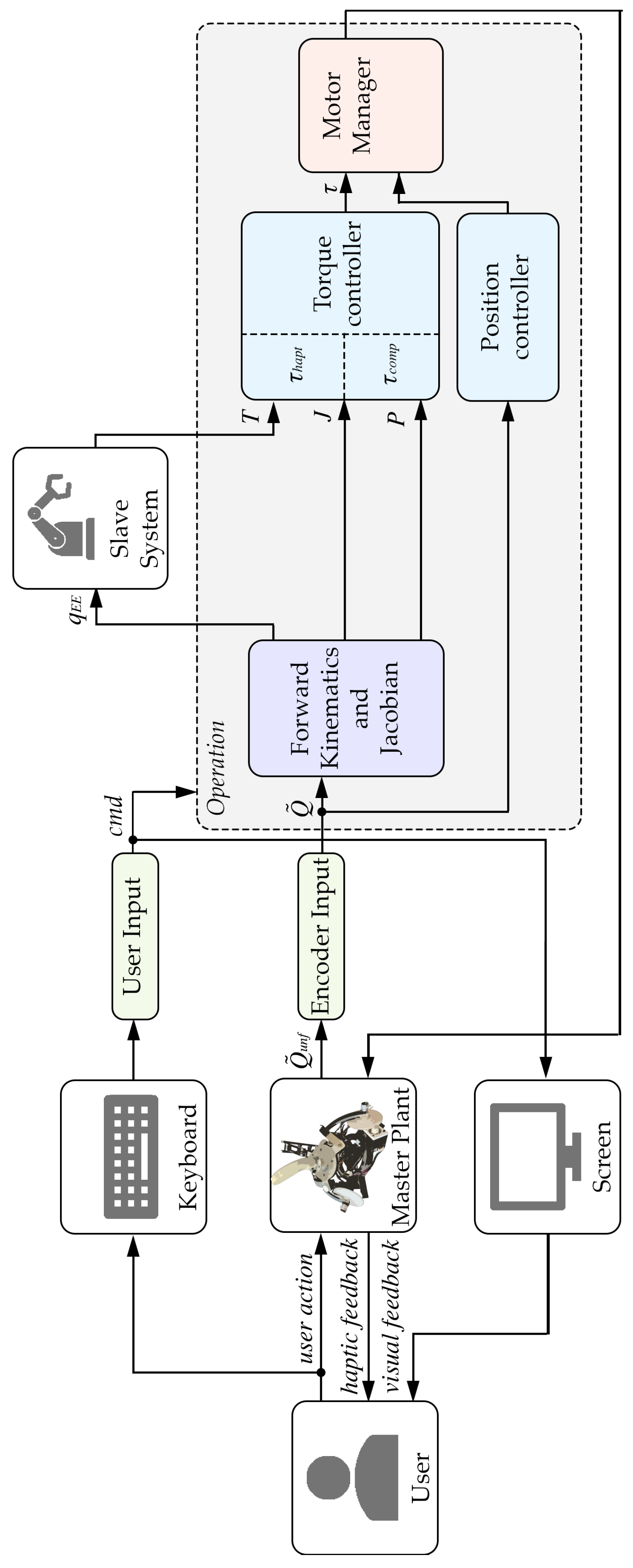
Nevertheless, the Simplex Motion (Gothenburg, Sweden) SC040B motors [46], whose specifications are reported in Table A1 (in Appendix A), support both torque and position control modes, allowing the device to operate in both types of control, as schematically shown in Figure 6.

2.3. Reset Control Mode and Its Implementation

2.3.1. Overview

The fundamental principles of the reset control mode were introduced in [37]. This section aims to provide a deeper understanding of the mode and expand upon its implementation and functionality.
As from general theory, a path planning algorithm can either be implemented in the joint space coordinates Q = ( θ 1 A ,   θ 1 B ,   θ 1 C ) or in the generalized coordinates in P = ( ψ ,   θ ,   ϕ ) . Due to the goal simplicity of the reset mode, the research has focused on joint-space path planning, less intuitive but not requiring the use of the inverse kinematics thoroughly presented in [36] and introduced in Section 2.1. On the other hand, joint-space path planning requires additional a priori considerations as aspect A 3 is non-convex, as shown in Figure 5, and, hence, path planning feasibility is non-trivial.

2.3.2. Path Planning Optimization Problem

The Point-to-Point (PTP) joint path planning described in [37] hence faces an optimization procedure, which considers the following constraints:
(C1)
As previously mentioned, the path s must be feasible, i.e., entirely inside A 3 , hence without entering dominions such as S J , 3 (low-dexterity) and C V , 3 (self-collision), as described in Section 2.1:
F e a s i b i l i t y s o p ( Q 0 , Q 1 , , Q k , Q f ) A 3
In which point Q 0 corresponds to a generic point Q inside A 3 ; point Q f = Q C = ( 45.0 ,   11.9 ,   101.9 ) ° corresponds to workspace center C ; k is the number of intermediate points output from the PTP algorithm.
(C2)
To reduce both resetting time and motor energy usage, the path must follow the shortest possible trajectory:
| | s o p | | = min ( Q 1 , , Q k ) A 3 | | Q 0 , 1 | | + . + | | Q k , f | |
In which Q i , i + 1 = Q i + 1 Q i , i.e., the segmented trajectory between the two points.
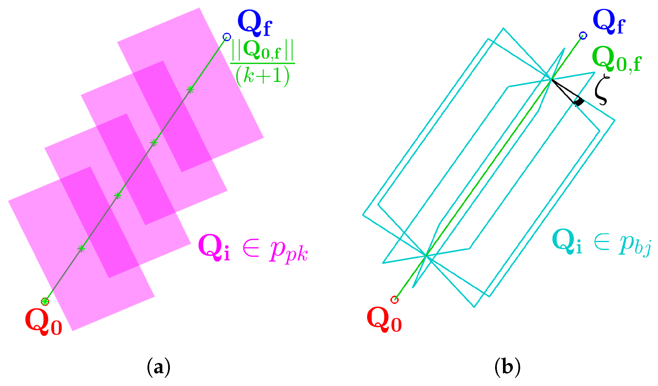
The PTP optimization problem can be additionally simplified to reduce calculation time by relaxing (C2), according to Figure 7 and the following constraints:
(C3)
Points Q i | i = 1 , , k are constrained to lie on a series of equidistant parallel planes p p k , spaced by a distance of | | Q 0 , f | | / ( k + 1 ) , as illustrated in Figure 7a;
(C4)
Points Q i | i = 1 , , k are constrained to lie on a common plane p b j , selected from a bundle of planes sharing an axis aligned with Q 0 , f and separated by a fixed rotation angle ζ , as shown in Figure 7b.
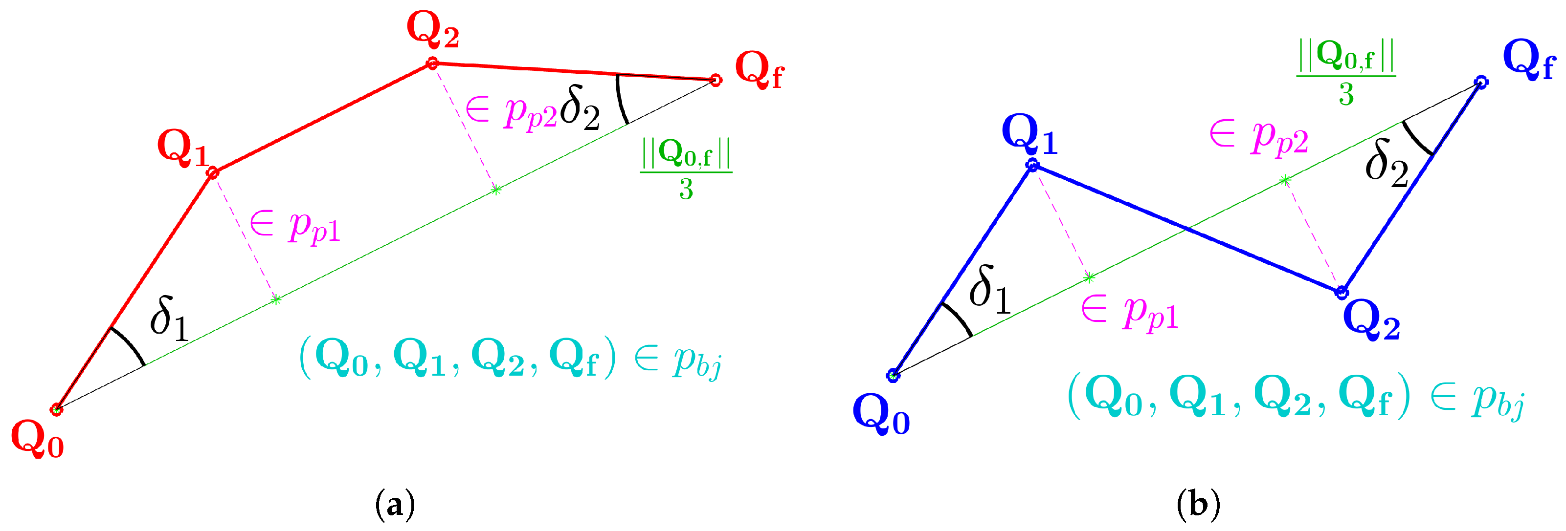
It can be demonstrated that the minimal number of intermediate points k to satisfy (C1) is k = 2 , hence configuring two possible PTP trajectories aside from the straightforward trivial one Q 0 , f , namely “cis” and “trans”, as in Figure 8. A final simplifying constraint, applicable only if k = 2 , states that
(C5)
Angles δ 1 and δ 2 , defined as the angles between Q 0 , f , Q 0 , 1 , and Q f , 2 , respectively, are constrained to be equal, i.e., δ = δ 1 = δ 2 .
The general optimization problem, introduced in (6), is thus reduced in optimizing angles ( ζ , δ ) within geometrically relevant limits:
| | s o p | | = min ( Q 1 , , Q k ) A 3 | | Q 0 , 1 | | + + | | Q k , f | | s . t . ( C 1 ) , ( C 2 ) (7a)   min ( Q 1 , Q 2 ) A 3 | | Q 0 , 1 | | + | | Q 1 , 2 | | + | | Q 2 , f | | s . t . ( C 1 ) , , ( C 5 ) (7b)   min δ ( π 2 , π 2 ) ζ [ 0 , π ) | | Q 0 , 1 | | + | | Q 1 , 2 | | + | | Q 2 , f | | s . t . ( C 1 ) , , ( C 5 ) (7c)

2.3.3. Implementation

The path planning algorithm, deriving from the optimization problem (7) described in Section 2.3.2, was integrated into the general control logic presented in Section 2.2 and illustrated in Figure 6 by switching the driver’s mode from torque control to position control, as outlined in that section. A pseudo-code flowchart rendition of the full path planning algorithm can be found in Figure A1 in Appendix A. The overall control architecture was implemented through separate Python nodes within an ROS Noetic environment.
Once the toggling happens, the current position Q is used as the initial input Q 0 for the optimization algorithm. Leveraging a predefined representation of A 3 , the algorithm computes the intermediate points Q 1 and Q 2 required to reset the device to the target position Q f = Q C . The motor’s driver, configured as detailed in Table A3, then executes the motion toward each point sequentially, following a standard trapezoidal velocity profile. Angles Q ˜ = ( Q , θ 2 C ) = ( θ 1 A , θ 1 B , θ 1 C , θ 2 C ) are measured by MAB18A Hall-effect encoders by MEGATRON Elektronik (Putzbrunn, Germany) [47], whose specifics are detailed in Table A2.
During motion, the internal logic of the Position Controller node, shown in Figure 6, continuously compares the feedback signal Q with the current goal position Q i | i = 1 , 2 , f . This allows the system to either switch to the next target (for i = 1 ,   2 ) or complete the reset procedure (for i = f ) once the device reaches a sufficiently close neighborhood of Q i . The tolerance defining this neighborhood can be adjusted based on precision requirements; for the current implementation, it was preliminarily set to 0.5 ° . Other position control parameters were also set according to Table A3 but will require further tuning as part of future development efforts.

2.4. Workbench Materials

As a preliminary step for evaluating the reset control mode in Section 2.3, the following workbench environment was implemented:
  • The qSPM device, whose kinematics have been analyzed Section 2.1, mounting the Simplex Motors’ driver set according to Table A1 and described in Section 2.2;
  • An Arduino UNO board (Arduino S.r.l., Monza, Italy) [48], responsible for acquiring, for the reset mode, feedback signal Q ;
  • A laptop running the ROS Noetic 1.16 environment, detailed in Section 2.3.3 for the qSPM application, and hosting the overall control scheme, which follows the structure illustrated in Figure 6.
    The laptop is directly connected via USB ports to both the qSPM device motor drivers and the Arduino UNO board;
    An additional ROS node is implemented to acquire and log all relevant signals for subsequent experimental analysis;
    Since this paper only focuses on the master device control architecture, the haptic feedback loop with the slave system was turned off.

2.5. Evaluation Methodologies

The resulting PTP algorithm and control architecture are tested to evaluate their feasibility and computation and operational times. The test is composed of three trials:
(Ex1)
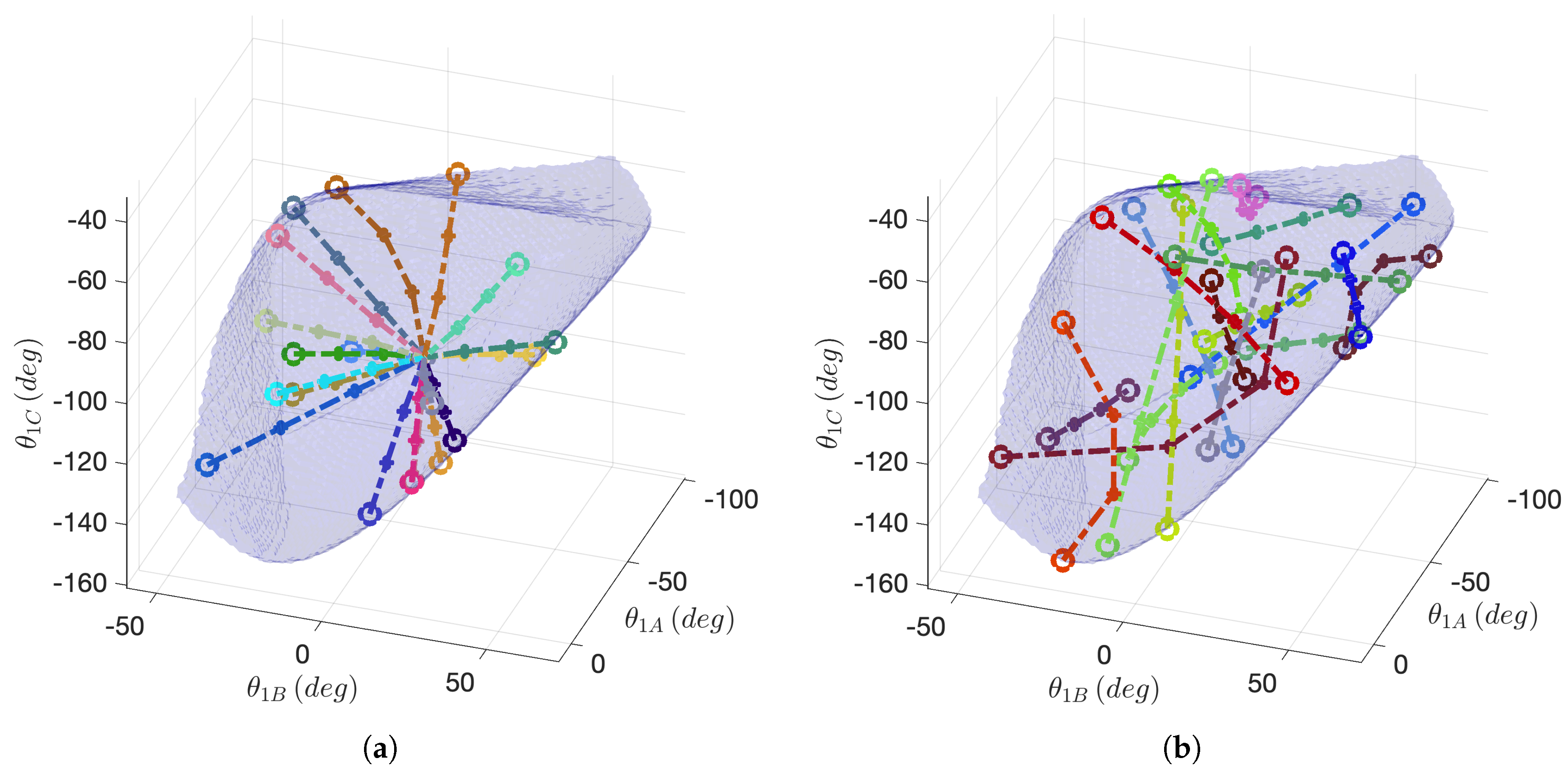
Following the optimization problem described in (7c) in Section 2.3.2, the algorithm is tested for its feasibility and calculation time for a discrete number N Q 0 = 50 of random points on the surface A 3 (3), selected as Q 0 with Q f = Q C , as in (C1);
(Ex2)
With the intention of expanding reset mode capabilities in future implementations, said optimization problem is tested for a discrete number of N Q 0 = N Qf = 50 random points on the surface A 3 (3), considered as both Q 0 and Q f ;
(Ex3)
The device is first adjusted and set in four random points Q 0 , i | i = 1 , , 4 A 3 (3), as in Table 1, and reset through the control architecture presented in Section 2.3.3 to Q C . The feedback values of Q are hence compared with the output PTP path ( Q 0 , Q 1 , Q 2 , Q f = Q C ) , which is provided to the motors as a reference position. The objective is to evaluate the time performance of the implemented path planning algorithm.
Note that (Ex1) and (Ex2) are both conservative with respect to the actual resetting operation of the device presented in Section 2.3.3 as points in surface A 3 represent the worst-case scenario. Due to this conservativeness, both experiments are demonstrated to validate the resetting mode operation for every point in A 3 (3).

3. Results

This section is devoted to presenting the results of (Ex1), (Ex2), and (Ex3), introduced in Section 2.5, derived from the control structure from Section 2.3 and applied following Section 2.4.
The PTP algorithm described in Section 2.3 is successfully applied to both (Ex1) and (Ex2), introduced in Section 2.5 and illustrated in Figure 9a,b, respectively. Table 2 presents the time performance metrics (mean and standard deviation (Std)) obtained from the Python 3.11 script executed within the ROS environment described in Section 2.3.3. The evaluation considers three path morphologies: direct, cis or trans, and a general case, as detailed in Section 2.3.2.
Figure 10 shows significant reference and feedback signals from the four trials of (Ex3), namely P r = ( ψ r , θ r , ϕ r ) and Q ˜ = ( Q , θ 2 C ) = ( θ 1 A , θ 1 B , θ 1 C , θ 2 C ) , as angle θ 2 C is used for the computation of forward kinematics, as described in [36]. Finally, Table 3 shows the performance of said results in terms of 5 % settling time and average tracking error e Q = Q f Q C , demonstrating how the device successfully resets to workspace center Q C , as established in Section 2.3.2.

4. Discussion and Conclusions

This paper has focused on the reset mode testing of the Quasi-Spherical Parallel Manipulator (qSPM) as an extended version of a previous work of the same authors [37]. After presenting the necessary kinematics and control insights for the device’s architecture, this paper focused on the experimental evaluation of said control mode, featuring a PTP joint path planning algorithm constrained in Section 2.3.2 and (7), implemented in Section 2.3.3, and schematically portrayed in Figure A1. The algorithm was then preliminarily evaluated with three different experiments, (Ex1), (Ex2), and (Ex3), regarding the first considerations of both the calculation and operational performances. The results presented in Section 3 contribute to the following varying observations.
Regarding (Ex1), Table 2 demonstrates optimal performance outcomes, demonstrating how the simplified optimization problem is able to output feasible paths within aspect A 3 from random points in the aspect’s surface Q 0 A 3 (3) to aspect center Q f = Q C in milliseconds (<10 ms). Therefore, as previously mentioned in Section 2.5, the experiment demonstrates the feasibility of the reset control mode in all the points inside A 3 as the experiment, being applied on A 3 , is conservative. This poses the basis of a responsive and receptive mode, an aspect of paramount importance for the telesurgical application field.
The effectiveness of this resetting mode was further evaluated in (Ex2). As shown in Table 2, when both Q 0 and Q f lie on the surface A 3 , the optimization task becomes more demanding, resulting in higher computation times compared to (Ex1). Nonetheless, feasibility is maintained for all the tested cases, and the computation times remain within the same order of magnitude (<10 ms) of (Ex1). Even if this evaluation setup is currently not yet implemented in the resetting control mode, this experiment demonstrates the robustness of the optimization algorithm, which is capable of outputting feasible joint space PTP paths within all points A 3 .
Regarding (Ex3), Table 3 shows promising preliminary results. Even if the implementation of the reset mode has not yet been optimized, as described in Section 2.3.3, the device is able to smoothly reset in its central position in a matter of seconds, with 5 % settling time 5   s and an average residual error e ¯ Q , presented in Section 3, less than 0.25 ° . The nature of the error can be attributed to sensor precision, whose resolution is equal to 0.09 ° , as presented in Table A2, and other unmodeled errors entering the system, such as clearance and friction, a peculiar problem introduced in [39].
Considering the promising outcomes of (Ex2), future developments will certainly focus on the full implementation of a PTP control mode within any point of A 3 . In fact, this feature could play a key role in future developments, enabling the surgeon to smoothly readjust the master device within the local control loop, described in Section 1, to a more ergonomic position while minimizing the time the slave device remains stationary. Since the device will also include axial displacement actuation to enable full RCM functionality, future developments could focus on integrating this additional degree of freedom into the control mode, allowing the entire device to be adjusted according to the end user’s preferences. Furthermore, smoother position control strategies could be employed, beyond the trapezoidal velocity profile implemented in the motor firmware, in order to improve precision and reduce jerk. As previously noted, the optimization algorithm is still preliminary and will undergo a full parameter optimization and thorough testing during the next development phase to refine the control action and avoid the risk of local optimality within A 3 .

Author Contributions

Conceptualization, D.P.Q. and M.A.L.; methodology, D.M. and M.A.L.; project administration, M.A.L.; software, D.P.Q.; supervision, D.M. and M.A.L.; validation, D.P.Q., D.M., and M.A.L.; writing—original draft, D.P.Q.; writing—review and editing, D.P.Q. All authors have read and agreed to the published version of the manuscript.

Funding

This research received no external funding.

Institutional Review Board Statement

Not applicable.

Informed Consent Statement

Not applicable.

Data Availability Statement

Data is contained within the article.

Conflicts of Interest

The authors declare no conflicts of interest.

Abbreviations

The following abbreviations are used in this manuscript:
BTBilateral Teleoperation
BTSBilaterally Teleoperated System
DTDigital Twin
EEEnd Effector
HMIHuman–Machine Interaction
HMiHuman–Machine Interface
MISMinimally Invasive Surgery
PTPPoint-to-Point (joint path planning)
qSPMQuasi-Spherical Parallel Manipulator
RRevolute Joint
RCMRemote Center of Motion
StdStandard Deviation
UUniversal Joint
X Surface of Dominion X

Appendix A

Figure A1. Pseudo-code flowchart rendition of the optimization algorithm described in Section 2.3.3. Parameters and constraints (C1)…(C5) refer to Section 2.1 and Section 2.3.2.
Machines 13 00858 g0a1
Table A1. Motor SC040B by Simplex Motion (Gothenburg, Sweden) specifics.
SpecificValueUnit
Maximum Speed (@24V)6000[rpm]
Maximum Torque0.8[Nm]
Rated Torque0.28[Nm]
Power supply input voltage24[V]
Maximum continuous mechanical output power120[W]
Gear ratio (by crafted 3D-printed gears)200/23-
Table A2. Hall-effect absolute encoder MAB18A by MEGATRON Elektronik (Putzbrunn, Germany) specifics.
SpecificValueUnit
Angle range360[ ° ]
Angle resolution4096steps
Supply voltage5[V]
Supply current<20[mA]
Signal load>5[k Ω ]
Output voltage range0–5[V]
Table A3. Motor driver parameters, detailed in Section 2.3.3.
SymbolDescriptionValueUnit
-Maximum motor Torque100[mNm]
-Maximum motor quick stop Torque150[mNm]
-Maximum motor speed10[rpm]
-Maximum motor acceleration190[rpm/s]
-Maximum motor deceleration−190[rpm/s]
g r Gear ratio200/23-

References

  1. Ferrell, W.R.; Sheridan, T.B. Supervisory control of remote manipulation. IEEE Spectr. 1967, 4, 81–88. [Google Scholar] [CrossRef]
  2. Hokayem, P.F.; Spong, M.W. Bilateral teleoperation: An historical survey. Automatica 2006, 42, 2035–2057. [Google Scholar] [CrossRef]
  3. Evans, C.R.; Medina, M.G.; Dwyer, A.M. Telemedicine and telerobotics: From science fiction to reality. Updat. Surg 2018, 70, 357–362. [Google Scholar] [CrossRef] [PubMed]
  4. Choi, P.J.; Oskouian, R.J.; Tubbs, R.S. Telesurgery: Past, Present, and Future. Cureus 2018, 10, e2716. [Google Scholar] [CrossRef] [PubMed]
  5. Imaida, T.; Yokokohji, Y.; Doi, T.; Oda, M.; Yoshikawa, T. Ground-space bilateral teleoperation of ETS-VII robot arm by direct bilateral coupling under 7-s time delay condition. IEEE Trans. Robot. Autom. 2004, 20, 499–511. [Google Scholar] [CrossRef]
  6. Jakuba, M.V.; German, C.R.; Bowen, A.D.; Whitcomb, L.L.; Hand, K.; Branch, A.; Chien, S.; McFarland, C. Teleoperation and robotics under ice: Implications for planetary exploration. In Proceedings of the 2018 IEEE Aerospace Conference, Big Sky, MT, USA, 3–10 March 2018; pp. 1–14. [Google Scholar] [CrossRef]
  7. Goertz, R.C. Remote-Control Manipulator. U.S. Patent 2632574A, 24 March 1953. [Google Scholar]
  8. Sobrepera, M.J.; Nguyen, A.T.; Gavin, E.S.; Johnson, M.J. Insights into the deployment of a social robot-augmented telepresence robot in an elder care clinic – perspectives from patients and therapists: A pilot study. Robotica 2024, 42, 1321–1349. [Google Scholar] [CrossRef]
  9. Chu, M.; Cui, Z.; Zhang, A.; Yao, J.; Tang, C.; Fu, Z.; Nathan, A.; Gao, S. Multisensory Fusion, Haptic, and Visual Feedback Teleoperation System Under IoT Framework. IEEE Internet Things J. 2022, 9, 19717–19727. [Google Scholar] [CrossRef]
  10. Raison, N.; Khan, M.S.; Challacombe, B. Telemedicine in Surgery: What are the Opportunities and Hurdles to Realising the Potential? Curr. Urol. Rep. 2015, 16, 43. [Google Scholar] [CrossRef]
  11. Cazac, C.; Radu, G. Telesurgery–an efficient interdisciplinary approach used to improve the health care system. J. Med. Life 2014, 7, 137–141. [Google Scholar]
  12. Barba, P.; Stramiello, J.; Funk, E.K.; Richter, F.; Yip, M.C.; Orosco, R.K. Remote telesurgery in humans: A systematic review. Surg. Endosc. 2022, 36, 2771–2777. [Google Scholar] [CrossRef]
  13. Anderson, R.; Spong, M. Bilateral control of teleoperators with time delay. IEEE Trans. Autom. Control 1989, 34, 494–501. [Google Scholar] [CrossRef]
  14. Lee, D.; Li, P. Passive control of bilateral teleoperated manipulators: Robust control and experiments. In Proceedings of the 2001 American Control Conference. (Cat. No.01CH37148), Arlington, VA, USA, 25–27 June 2001; IEEE: New York, NY, USA, 2001; Volume 6, pp. 4612–4618. [Google Scholar]
  15. Niemeyer, G.; Slotine, J.J. Stable adaptive teleoperation. IEEE J. Ocean. Eng. 1991, 16, 152–162. [Google Scholar] [CrossRef]
  16. Fong, C.; Dotson, R.; Bejczy, A. Distributed microcomputer control system for advanced teleoperation. In Proceedings of the 1986 IEEE International Conference on Robotics and Automation, San Francisco, CA, USA, 7–10 April 1986; IEEE: New York, NY, USA, 1986; Volume 3, pp. 987–995. [Google Scholar]
  17. Mirfakhrai, T.; Payandeh, S. A delay prediction approach for teleoperation over the internet. In Proceedings of the IEEE International Conference on Robotics and Automation, Washington, DC, USA, 11–15 May 2002; Volume 2, pp. 2178–2183. [Google Scholar]
  18. Bejczy, A.; Kim, W.; Venema, S. The phantom robot: Predictive displays for teleoperation with time delay. In Proceedings of the IEEE International Conference on Robotics and Automation, Cincinnati, OH, USA, 13–18 May 1990; Volume 1, pp. 546–551. [Google Scholar]
  19. Slama, T.; Trevisani, A.; Aubry, D.; Oboe, R.; Kratz, F. Experimental Analysis of an Internet-Based Bilateral Teleoperation System With Motion and Force Scaling Using a Model Predictive Controller. IEEE Trans. Ind. Electron. 2008, 55, 3290–3299. [Google Scholar] [CrossRef]
  20. Oboe, R. Web-interfaced, force-reflecting teleoperation systems. IEEE Trans. Ind. Electron. (1982) 2001, 48, 1257–1265. [Google Scholar] [CrossRef]
  21. Sheridan, T.; Ferrell, W. Remote Manipulative Control with Transmission Delay. IEEE Trans. Hum. Factors Electron. 1963, HFE-4, 25–29. [Google Scholar] [CrossRef]
  22. Ghorbanian, A.; Zareinejad, M.; Rezaei, S.; Sheikhzadeh, H.; Baghestan, K. A novel control architecture for physiological tremor compensation in teleoperated systems. Int. J. Med Robot. Comput. Assist. Surg. 2013, 9, 280–297. [Google Scholar] [CrossRef] [PubMed]
  23. Morton, J.; Hardwick, R.H.; Tilney, H.S.; Gudgeon, A.M.; Jah, A.; Stevens, L.; Marecik, S.; Slack, M. Preclinical evaluation of the versius surgical system, a new robot-assisted surgical device for use in minimal access general and colorectal procedures. Surg. Endosc. 2021, 35, 2169–2177. [Google Scholar] [CrossRef]
  24. Fanfani, F.; Fagotti, A.; Rossitto, C.; Gagliardi, M.L.; Ercoli, A.; Gallotta, V.; Gueli Alletti, S.; Monterossi, G.; Turco, L.C.; Scambia, G. Laparoscopic, minilaparoscopic and single-port hysterectomy: Perioperative outcomes. Surg. Endosc. 2012, 26, 3592–3596. [Google Scholar] [CrossRef]
  25. Soper, N.; Swanström, L.; Eubanks, S. Mastery of Endoscopic and Laparoscopic Surgery; LWW medical book collection; Lippincott Williams & Wilkins: Ambler, PA, USA, 2008. [Google Scholar]
  26. Satcher, R.L.; Bogler, O.; Hyle, L.; Lee, A.; Simmons, A.; Williams, R.; Hawk, E.; Matin, S.; Brewster, A.M. Telemedicine and telesurgery in cancer care: Inaugural conference at MD Anderson Cancer Center: Telemedicine and Telesurgery in Cancer Care. J. Surg. Oncol. 2014, 110, 353–359. [Google Scholar] [CrossRef]
  27. Gambadauro, P.; Torrejón, R. The “tele”factor in surgery today and tomorrow: Implications for surgical training and education. Surg. Today 2013, 43, 115–122. [Google Scholar] [CrossRef]
  28. Mendivil, A.; Holloway, R.W.; Boggess, J.F. Emergence of robotic assisted surgery in gynecologic oncology: American perspective. Gynecol. Oncol. 2009, 114, S24–S31. [Google Scholar] [CrossRef]
  29. Leal Ghezzi, T.; Campos Corleta, O. 30 Years of Robotic Surgery. World J. Surg. 2016, 40, 2550–2557. [Google Scholar] [CrossRef]
  30. Chitwood, W.R.J. Historical evolution of robot-assisted cardiac surgery: A 25-year journey. Ann. Cardiothorac. Surg. 2022, 11, 564–582. [Google Scholar] [CrossRef]
  31. Fanfani, F.; Monterossi, G.; Fagotti, A.; Rossitto, C.; Alletti, S.G.; Costantini, B.; Gallotta, V.; Selvaggi, L.; Restaino, S.; Scambia, G. The new robotic TELELAP ALF-X in gynecological surgery: Single-center experience. Surg. Endosc. 2016, 30, 215–221. [Google Scholar] [CrossRef] [PubMed]
  32. Gueli Alletti, S.; Rossitto, C.; Cianci, S.; Perrone, E.; Pizzacalla, S.; Monterossi, G.; Vizzielli, G.; Gidaro, S.; Scambia, G. The Senhance™surgical robotic system (“Senhance”) for total hysterectomy in obese patients: A pilot study. J. Robot. Surg. 2018, 12, 229–234. [Google Scholar] [CrossRef] [PubMed]
  33. Quijano, Y.; Vicente, E.; Ferri, V.; Naldini, C.; Pizzuti, G.; Caruso, R. Robot-assisted Nissen fundoplication with the new HUGO™ Robotic assisted system: First worldwide report with system description, docking settings and video. Int. J. Surg. Case Rep. 2023, 106, 108178. [Google Scholar] [CrossRef] [PubMed]
  34. Saafi, H.; Laribi, M.A.; Zeghloul, S. Forward kinematic model improvement of a spherical parallel manipulator using an extra sensor. Mech. Mach. Theory 2015, 91, 102–119. [Google Scholar] [CrossRef]
  35. Meskini, M.; Saafi, H.; Mlika, A.; Arsicault, M.; Zeghloul, S.; Laribi, M.A. Development of a novel hybrid haptic (nHH) device with a remote center of rotation dedicated to laparoscopic surgery. Robotica 2023, 41, 3175–3194. [Google Scholar] [CrossRef]
  36. Pacheco Quiñones, D.; Maffiodo, D.; Laribi, A. Kinematic analysis, workspace definition, and self-collision avoidance of a quasi-spherical parallel manipulator. Robotica 2024, 43, 1955–1980. [Google Scholar] [CrossRef]
  37. Pacheco Quiñones, D.; Maffiodo, D.; Laribi, M.A. Joint Path Planning of the Quasi-Spherical Parallel Manipulator. In Proceedings of the Advances in Italian Mechanism Science; Quaglia, G., Boschetti, G., Carbone, G., Eds.; Springer: Cham, Switzerland, 2024; pp. 242–248. [Google Scholar]
  38. Pacheco Quiñones, D.; Maffiodo, D.; Laribi, M.A. Assistive Control through a Hapto-Visual Digital Twin for a Master Device Used for Didactic Telesurgery. Robotics 2024, 13, 138. [Google Scholar] [CrossRef]
  39. Pacheco Quiñones, D.; Maffiodo, D.; Laribi, M.A. Workbench Statics Evaluation of the Quasi-Spherical Parallel Manipulator. In Proceedings of the New Trends in Medical and Service Robotics; Laribi, M.A., Carbone, G., Pisla, D., Zeghloul, S., Eds.; Springer: Cham, Switzerland, 2025; pp. 74–81. [Google Scholar]
  40. Gosselin, C.; Angeles, J. Singularity Analysis of Closed-Loop Kinematic Chains. Robot. Autom. IEEE Trans. 1990, 6, 281–290. [Google Scholar] [CrossRef]
  41. Bonev, I.; Chablat, D.; Wenger, P. Working and assembly modes of the agile eye. In Proceedings of the 2006 IEEE International Conference on Robotics and Automation, Orlando, FL, USA, 15–19 May 2006; ICRA 2006. IEEE: New York, NY, USA, 2006; pp. 2317–2322. [Google Scholar]
  42. Cristancho, S.M.; Vanstone, M.; Lingard, L.; LeBel, M.E.; Ott, M. When surgeons face intraoperative challenges: A naturalistic model of surgical decision making. Am. J. Surg. 2013, 205, 156–162. [Google Scholar] [CrossRef]
  43. Nowlin, W.C.; Guthart, G.S.; Salisbury, J.K.; Niemeyer, G.D. Repositioning and Reorientation of Master/Slave Relationship in Minimally Invasive Telesurgery. U.S. Patent 7806891B2, 5 October 2010. [Google Scholar]
  44. Chablat, D.; Wenger, P. Working modes and aspects in fully parallel manipulators. In Proceedings of the 1998 IEEE International Conference on Robotics and Automation (Cat. No.98CH36146), Leuven, Belgium, 16–21 May 1998; Volume 3, pp. 1964–1969. [Google Scholar] [CrossRef]
  45. Merlet, J.P. Jacobian, Manipulability, Condition Number, and Accuracy of Parallel Robots. J. Mech. Des. (1990) 2006, 128, 199–206. [Google Scholar] [CrossRef]
  46. Simplex Motion SC-Series. Available online: https://simplexmotion.com/integrated-servomotors/sc-series/ (accessed on 15 July 2025).
  47. Megatron Hall-Effect Absolute Encoder Series MAB18A. Available online: https://www.megatron.de/en/products/more-products-angle-sensors/hall-effect-absolute-encoder-series-mab18a.html (accessed on 15 July 2025).
  48. Arduino UNO Technical Documentation. Available online: https://docs.arduino.cc/hardware/uno-rev3 (accessed on 15 July 2025).
Figure 1. Bilaterally teleoperated main control loops: local control loop (red), remote control loop (green), and teleoperation control loop (blue).
Machines 13 00858 g001
Figure 2. The Quasi-Spherical Parallel Manipulator: (a) photo of the current prototyped device; (b) kinematic scheme (where U and R denote Universal and Revolute joints, respectively; underlined joints are actuated).
Machines 13 00858 g002
Figure 3. Device’s key nomenclature: (a) end effector’s orientation Euler’s triplet P = ( ψ , θ , ϕ ) ; (b) actuated angles Q = ( θ 1 A , θ 1 B , θ 1 C ) .
Machines 13 00858 g003
Figure 4. Working mode m 3 reachable workspace W r e a c h , 3 (2) (red) inside the application workspace W a p p (blue). Workspace center point C (black).
Machines 13 00858 g004
Figure 5. Working mode m 3 restricted aspect A 3 (3) (red).
Machines 13 00858 g005
Figure 6. Schematized overall control architecture of the qSPM device. Signal Q ˜ = [ Q , θ 2 C ] as angle θ 2 C is used in the calculation of forward kinematics.
Machines 13 00858 g006
Figure 7. Visual rendition of simplifying constraints (C3) and (C4): (a) stack of equidistant planes according to (C3); (b) bundle of planes with axis Q 0 , f according to (C4).
Machines 13 00858 g007
Figure 8. PTP possible non-trivial path morphologies considering constraints (C1),…, (C5): (a) cis morphology; (b) trans morphology.
Machines 13 00858 g008
Figure 9. PTP paths: paths from (Ex1), from points in A 3 (3) to workspace center Q C , as introduced in (C1) (dash-dotted color lines) (a); paths from (Ex2), from and to points in A 3 (b). To ensure readability and demonstrate diversity, only 20 non-direct points were selected.
Machines 13 00858 g009
Figure 10. Results of the four trials of (Ex3), having, as explained in Table 1, different Q 0 , i and Q f = Q C (ad). Reference PTP signals are dashed. Signal P r is derived from forward kinematics.
Machines 13 00858 g010
Table 1. Coordinates of four random points in Q 0 A 3 [ ° ] used in (Ex3).
Trial θ 1 A , 0 θ 1 B , 0 θ 1 C , 0
1−71.416.1−74.4
2−29.3−32.1−72.7
3−59.410.8−52.0
4−89.336.1−97.4
Table 2. Calculation time performance results of (Ex1) and (Ex2): mean and standard deviation calculation time values of the different path morphologies, as described in Section 2.1, and the general case, in which both are calculated. All values in [ms].
ExperimentTrialTime Performance
(Path Morphology) Mean Std
Direct6.991.30
(Ex1)Cis or Trans8.171.67
General7.122.01
Direct6.890.57
(Ex2)Cis or Trans7.482.09
General7.222.39
Table 3. Performance results related to output values Q = ( θ 1 A , θ 1 B , θ 1 C ) of (Ex3) settling time t s , X | X = 1 A , 1 B , 1 C ( 5 % tolerance band) and the residual mean error e ¯ X | X = 1 A , 1 B , 1 C within the band.
Trial t s , 5 , 1 A [s] t s , 5 , 1 B [s] t s , 5 , 1 C [s] e ¯ 1 A [ ° ] e ¯ 1 B [ ° ] e ¯ 1 C [ ° ]Figure
14.53.94.90.680.010.19Figure 10a
25.07.05.3−0.280.10−0.32Figure 10b
34.64.47.80.890.270.71Figure 10c
46.85.24.20.86−0.12−0.17Figure 10d
Avg5.25.15.60.540.070.10
Disclaimer/Publisher’s Note: The statements, opinions and data contained in all publications are solely those of the individual author(s) and contributor(s) and not of MDPI and/or the editor(s). MDPI and/or the editor(s) disclaim responsibility for any injury to people or property resulting from any ideas, methods, instructions or products referred to in the content.