Abstract
This paper compares two multi-objective optimization strategies for spiral-grooved dynamic gas thrust bearings. The first optimization is carried out using an analytical model, which is valid under the assumption of a high number of grooves. The second one is carried out by using a numerical model based on a finite difference (FD) technique, which is valid also in case of a limited number of grooves. The FD model was validated with data from the literature, then it was compared with the analytical model. The multi-objective optimization is based on a genetic algorithm and it is aimed at maximizing the load-carrying capacity (LCC) of the thrust bearing while minimizing its friction torque. It was found that the analytical model overestimates both the friction torque and the load capacity compared to the FD model, and that the Pareto front optimizations reveal almost identical trends in the optimized parameters.
1. Introduction
Aerodynamic grooved bearings have special properties that make them suitable for portable high-speed applications, e.g., heat pumps [1], fuel cell blowers [2,3], or recirculation devices [4]. Indeed, they do not need auxiliary compression systems, as the pressure distribution that creates the load-carrying capacity is due to the pumping effect generated by the grooved shaft rotation and the low viscosity of the fluid that makes them suitable for high-efficiency systems. Driven by the trend of downsizing turbomachinery, the use of aerodynamic grooved bearings has been rapidly increasing in the last two decades.
However, the optimal design of aerodynamic grooved bearings is not a trivial task since it depends on several interrelated geometric and operating parameters that can affect their functioning and stability. The working principle of aerodynamic grooved thrust bearings depends on the relationship between the amount of fluid that is pumped into the clearance, i.e., the pump effect, and the amount of fluid that is leaked out from it. The leakage out of the clearance is a consequence of the pressure developed by the pump effect and the grooves’ geometry; e.g., if the grooves are too deep, the leakage will be excessive, while if the groove depth is reduced to zero the pump effect vanishes. Since “natura non facit saltus”, it should be always possible to optimize the groove geometry depending on the selected cost functions.
Concerning the modelling of grooved bearings, analytical or numerical approaches can be followed. The first model that tried to explain the groove pumping effect is from Whipple [5], who developed an analytical model for the estimation of the load capacity where grooves with linear profile were considered. Successively, Muijderman [6] improved the model by considering the effect of the groove curvature through a logarithmic spiral function. Such models are part of the so-called Narrow Groove Theory (NGT), which assumes that the bearing has an infinite number of grooves. This assumption makes it possible to simplify the mathematical formulation of the problem, i.e., the pressure variation across the groove/ridge interface can be neglected and the pressure distribution across the bearing linearized, which can be solved analytically [7]. The NGT theory was also employed to calculate the dynamic coefficients of grooved bearings [8].
However, the accuracy of NGT is strictly related to the geometry and the number of grooves that are considered. The use of custom-built geometries and a small number of grooves requires the implementation of Finite Difference (FD) or Finite Element (FE) models. Recently, Huang et al. [9] developed a numerical model of a water-lubricated spiral-grooved thrust bearing (SGTB) for motorized spindles, based on the generalized Reynolds equation solved with the finite control volume method in a boundary-fitted coordinate system. The model, which also accounts for turbulence and tilting effects, was coupled with a flexible rotor–bearing system and validated against experimental data, showing good agreement in predicting the static performance of the bearing. Waumans et al. [10] presented the design and testing of aerodynamic grooved thrust bearings intended for micro turbomachinery applications. The study combined a numerical parameter analysis, based on the finite-difference solution of the Reynolds equation with grid mapping techniques, to evaluate the influence of groove geometry on load capacity and viscous losses. Different groove configurations, including inward spiral and herringbone types, were fabricated and experimentally tested up to 240,000 rpm. The comparison between simulations and measurements showed reasonable agreement, highlighting both the potential and the challenges of aerodynamic thrust bearings at the micro scale.
Many analytical and numerical models were employed to optimize the performance of aerodynamic grooved thrust bearings. Hashimoto et al. [11] optimized the groove depth, groove width ratio, and number of grooves of a Herringbone-Grooved Thrust Air Bearing (HGTAB) to enhance its performance at a fixed bearing load of 14.7 N over a rotating speed range from 20 to 80 krpm. Similarly, Zhang et al. [12] optimized the load capacity of an HGTAB by investigating the effects of groove depth, air film thickness, groove angle and number of grooves. Hashimoto and Namba [13] performed an optimization for a given load by considering five different objective functions: flying height, friction torque, dynamic stiffness, the product of the bearing flying height and dynamic stiffness, and the ratio of the friction torque and dynamic stiffness. Hashimoto and Ochiai [14] proposed a new optimization method that make it possible to design new groove shapes to obtain higher bearing stiffness. Fesanghary and Khonsari [15] developed a shape-optimization framework for parallel flat-surface thrust bearings that maximizes load-carrying capacity (LCC) by tailoring periodic groove geometry. Experiments validated the theory and demonstrated 14–36% higher LCC than conventional logarithmic spiral grooves.
In the attempt of achieving higher load capacity, Yu et al. [16] proposed a novel prototype of aerodynamic thrust bearing that mimics the surface structure of dragonfly wings. Compared to an optimized spiral-groove geometry, the dragonfly exhibits higher load capacity over all the rotating speed ranges investigated (from 45 to 90 krpm). Although single- and multi-objective optimization procedures make it possible to obtain significant performance improvement, they require the use of high-performance calculators.
This paper investigates a novel methodology to reducing the computational efforts of multi-objective optimizations for a Spiral-Groove Thrust Bearing (SGTB). The paper describes the first part of a study where the results related to two different kinds of multi-objective Pareto front optimizations of an SGTB are compared. The objective functions are the load capacity and the friction torque of the bearing. The first kind of optimization is obtained by means of the analytical model proposed by Mujiderman in [17]. The second one is performed by means of an incompressible FD model of the same bearing. The results obtained from these models are compared to assess whether, and under which conditions, Mujiderman’s model can provide results sufficiently close to those of the FD model, thereby justifying its use as a computationally efficient alternative.
2. Materials and Methods
Figure 1 shows the geometry of a spiral-grooved thrust bearing (SGTB). Inward pumping groove configuration is considered in this work since the pump-in design was confirmed to guarantee superior load-carrying capacity (LCC) compared to the other designs according to the previous literature evidence [18]. Grooves’ edges are defined by a set of logarithmic spiral curves [19,20] whose equation in polar coordinates reads as Equation (1).
where K is number of grooves, i are odd indices lower than K and j are even indices lower than K, is the circumferential length of a groove at radius r, is the circumferential length of a ridge at radius r. Due to the properties of the logarithmic spiral, the α angle and the ratio are constant whatever the radial position.
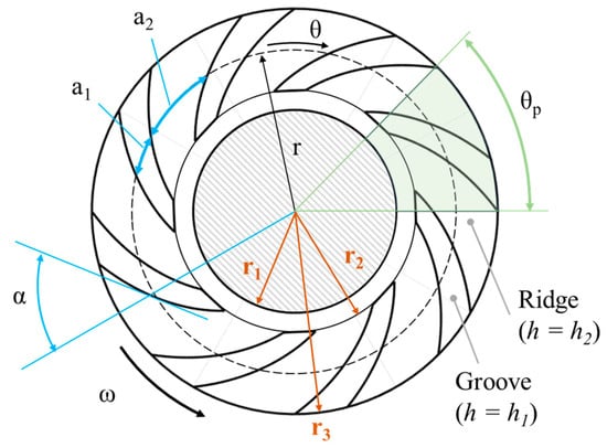
Figure 1.
Characteristic geometrical parameters of an SGTB. is the rotational speed of the smooth thrust discs against the stationary grooved disc.
The overall dimensions and operational conditions of the bearing considered for optimization in this paper are reported in Table 1. The operating fluid is air, whose dynamic viscosity is Pa∙s and density = 1.22 kg/m3. The bearing is supposed to be operated with stationary grooved surface and rotating flat surface. The design parameters are Y, X, H0, and α. X represents the groove-to-ridge ratio, Y the grooved-to-ungrooved ratio in the radial direction of the bearing, and is the groove depth.

Table 1.
Geometrical parameters of SGTB investigated in this paper.
2.1. Finite Difference Model
The full Reynolds Equation (RE) is solved through a finite difference (FD) technique with periodic and Dirichlet boundary conditions [19,20] within a computational domain that reproduces the film shape between the plates of an SGTB.
Equation (2) is the dimensionless stationary RE in polar coordinates valid for an isoviscous and incompressible fluid (in the following, capital letters identify dimensionless quantities). Dimensionless formulation is expedient to limit the number of input parameters and reduces truncation errors. The dimensionless variables read as per Equation (3) and reference parameters have been selected according to Equation (4).
In the above equations, the rotating speed of the moving surface about the symmetry axis is the local film thickness, is the dynamic viscosity, and is the periodicity angle (Figure 1). Due to the symmetry of the problem, the implemented FD model considers only a representative k-th portion of the bearing geometry. The assumption of isoviscous and incompressible fluids was applied to be consistent with the hypothesis of the model by Muijderman.
Figure 2 shows the computational domain in polar coordinates . As to the boundary conditions (b.c.), Dirichlet boundary conditions apply to the upper and lower bounds of the domain (black nodes), and , whereas periodic b.c. apply to the left and right bounds (green nodes), i.e., across the θ coordinate. Blue nodes are unknown internal nodes, whereas red nodes are unknown internal nodes with one known term (due to Dirichlet boundary conditions).
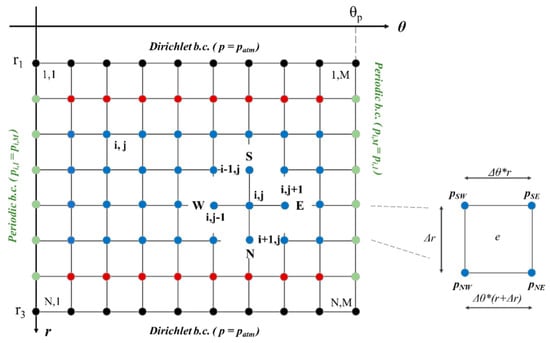
Figure 2.
Computation grid of the FD model.
The FD discretization scheme with central derivative approximation is applied to solve the RE. Due to the hypothesis of incompressible fluid, the differential equation becomes the linear system of algebraic equations of Equation (5), which is solved through the Gaussian elimination method. is an eptadiagonal matrix.
where N and M are the number of nodes of the computational grid along the radial and circumferential directions. Once the pressure distribution is solved in Matlab 2020 by matrix inversion (), the load-carrying capacity (Equation (6)) and the dimensionless load-carrying capacity (Equation (8)) are estimated by numerical integration of pressure across the computational domain. The area of the e-th element of the grid was calculated through (Equation (8)), and multiplied by the average of the pressure at nodes.
Friction torque (Equation (10)) and dimensionless friction torque (Equation (11)) were calculated by integrating the shear stress. Equation (9) is the shear stress acting on the moving thrust surface across the computational domain.
2.2. Analytical Model
The NGT model proposed by Muijderman [6] is considered here to carry out this optimization in a simplified way. The model with transverse flow which neglects end-effects of grooves is considered in this paper. Equations (12)–(20) are useful to calculate the LCC of a partially grooved thrust bearing, whereas Equation (16) is needed to calculate its friction torque. Equation (19) is for the transverse flow across the bearing. Corresponding dimensionless quantities are listed considering the same reference parameters as for the previous section.
where , and subscripts gr and ungr identify terms related to the grooved and ungrooved area of the thrust surface.
2.3. Optimization Algorithm
For the optimization of the SGTB geometry, a multi-objective optimization was carried out using a non-dominated sorting genetic algorithm with a population size of 64 individuals and 60 generations. The input parameters are that are varied within the ranges defined in Table 2. The optimization strategy aimed at maximizing the load-carrying capacity LCC and minimizing the friction torque . Weight factors were applied to the objective functions, i.e., 0.55 to LCC and 0.45 to . The authors attributed more importance to the LCC because preliminary investigations revealed that LCC is more affected by the design parameters than friction torque, which varies in a narrower band even with values of the design parameter far from an optimized configuration.

Table 2.
Input ranges for the optimization algorithm.
Constraints were enforced by penalizing infeasible solutions in the objective function evaluation. The optimization was terminated either upon reaching the maximum number of generations or when the improvement in the Pareto front hypervolume over 10 consecutive generations fell below a predefined threshold. Each optimization run was repeated three times with different random seeds to ensure statistical robustness.
The optimization ran with both the numerical and the analytical models to understand the difference between the two approaches and identify if there are ranges of input parameters where the simplified but less computationally expensive analytical model can be used in place of the FD one.
3. Results
3.1. Validation of the FD Model
The FD code used by the authors was first validated against data from a similar numerical simulation reported in the literature. Figure 3 provides a comparison of the LCC values presented by Zhang et al. [21] and those simulated by the authors in the same operating conditions. Since in this paper the incompressible RE was resorted to, validation of the numerical model is carried out considering a liquid fluid; in the case of Zhang et al. the operating fluid is water.
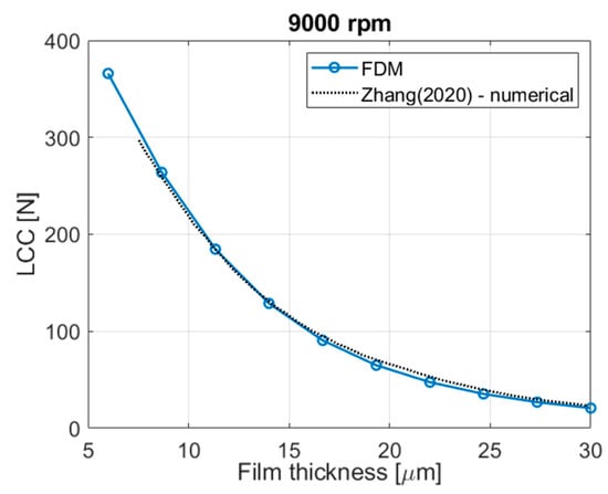
Figure 3.
Validation of the FD model against the results presented by Zhang et al. [21].
3.2. Convergence Analysis
The convergence analysis of the numerical model was carried out to select the optimal number of nodes to discretize the computation domain along the r-direction and θ-direction for the multi-objective optimization. The minimum number of nodes which guarantee negligible deviation in the estimated value of the load-carrying capacity was selected to minimize the time needed to run the multi-objective optimization code.
The results of the convergence analysis (Figure 4) show that with 12 grooves grids denser than 150 × 150 nodes produce an estimate of the LCC that differs less than 2% with respect to 300 × 300 nodes; therefore, a grid populated by 150 × 150 nodes was selected for the optimization to save computational time.
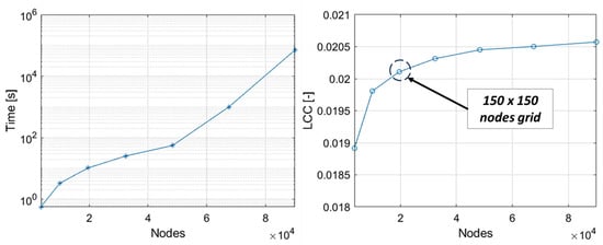
Figure 4.
LCC and computational time with increasing the number of nodes in the FD model from 60 × 60 nodes to 300 × 300 nodes. The convergence analysis was carried out considering an SGTB where X = 1.395, Y = 0.737, α = 17°, n = 70,000 rpm.
3.3. Comparison of Numerical vs. Analytical
The preliminary comparison between the two models used in this paper is presented in Figure 5 and Figure 6. To this end, the rotational speed was increased from 5000 rpm to 100,000 rpm for a given bearing geometry. Both the LCC and increase linearly with speed because the operating fluid is incompressible. As expected, the analytical NGT model overestimates the value of LCC and due to the hypothesis of an infinite number of grooves, and the deviation between the models is higher when the speed is higher. By increasing the number of grooves, the self-pumping effect is expected to be more effective [6] while the groove edge effects that produce localized pressure drops vanish (edge effects are indeed neglected in the Muijderman NGT).
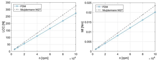
Figure 5.
Evolution of the LCC and friction torque with increasing rotational speed. The analysis was carried out considering an SGTB where X = 1.395, Y = 0.737, h1 = 39 μm, α = 17°, mm, mm, μm.
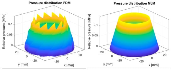
Figure 6.
Comparison between the pressure increase through the SGTB calculated by the numerical code and the analytical model by Muijderman; working conditions are the same as for Figure 5 with n = 60,000 rpm.
3.4. Multi-Objective Optimization
Figure 7 shows the results of the multi-objective optimization, with the two Pareto fronts being highlighted. The computational time in the case of the FD model was more than double the time needed by the optimization through the Muijderman model, i.e., about 36 h and 12 h, respectively, running on a desktop PC equipped with a Intel Xeon E-2126G 3.20 GHz processor. The orientation and shape of the two fronts are similar, which means that the relationship between the two objective functions is well described by the simplified analytical model. However, the Pareto front computed by the Muijderman model appears shifted with respect to that obtained via the FD one.
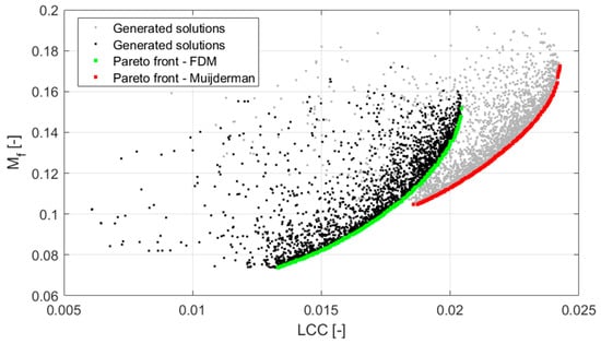
Figure 7.
The outcome of the genetic algorithm highlighted the two Pareto fronts obtained using the analytical model and the numerical one.
To shed light on the difference between these two Pareto fronts, the trends of the optimized parameters (, , and ) were analyzed. Figure 8 shows the trends of the optimized parameters versus the friction torque . As can be seen, the trends of these curves present similar shapes, but Muijderman’s model overestimates the dimensionless friction torque of about 0.025 with respect to that computed via FDM. Similarly, Figure 9 shows that, also in this case, the LCCs obtained by Muijderman’s model overestimate of about 0.004 that computed via FDM. These results are in line with those presented in Section 3.3.
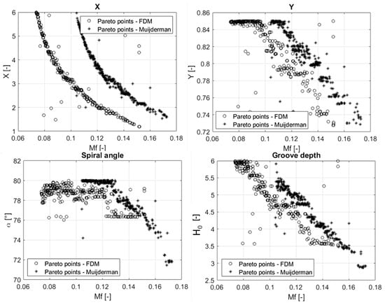
Figure 8.
Optimization parameters related to the points lying on the Pareto fronts plotted against the friction torque.
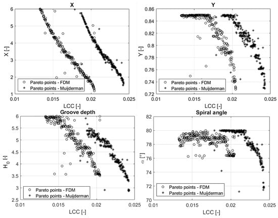
Figure 9.
Optimization parameters related to the points lying on the Pareto fronts plotted against the load-carrying capacity.
The angle of the logarithmic spiral grooves is optimum in a narrow band between 76° to 78° according to the FD model, whereas Muijderman’s model suggests a larger variability between 72° and 80°. X and H0 take very similar values evenly distributed in the whole design range according to both the models, but same values always correspond to a higher LCC and a higher Mf according to the analytical model. Such discrepancy is reasonably related to the simplifying hypothesis introduced by the NGT and addressed in Section 3. A similar consideration is put forward for Y. Optimized Y values are similar, but they vary in a restricted range close to the upper bound of the design range.
These results suggest that the Muijderman’s model can provide a rough idea of the performance of an SGTB and how the design parameters should evolve to optimize for either LCC or Mf, but using this model instead of a more refined numerical model is not conservative from an engineering point of view. A Muijderman-based optimization task may lead to overestimation of the performance of SGTBs and misleading values of the design parameters of the bearing, at least for a bearing of the size and shape addressed by the authors in this paper. Eventually, the difference between Muijderman and FD models may be due to the fact that the investigated bearing geometry does not have a sufficiently high number of grooves compared with an NGT model.
4. Conclusions
In this paper a multi-objective optimization of the geometry of a spiral-groove thrust bearing was carried out with two different models: a numerical model based on the FD technique and an analytical model by Muijderman. In both cases, the goal was to maximize the load capacity and minimize the friction torque of the bearing.
Comparison between the two methodologies aims at investigating if the optimization work through an analytical model can prevent the use of a more complex numerical simulation in order to reduce the computational efforts, at least in preliminary stage of the design of an SGTB, with sufficient accuracy.
The performed analysis demonstrates that, for the investigated bearing geometry, the Muijderman model overestimates the friction torque and load capacity with respect to the FDM. However, the Pareto fronts and the trends of the related optimized parameters are almost identical. This may be explained by the fact that the considered bearing geometry does not have a sufficiently high number of grooves compared with an NGT formulation.
These preliminary results indicate, therefore, that the effectiveness of the investigated method depends on the specific bearing geometry. In particular, the NGT theory provides results that are very close to those obtained with finite-difference models only for high numbers of grooves. In view of this, future work will further develop and extend this investigation, and it will focus on the use of more advanced analytical models. Further numerical and experimental investigations on various bearing geometries with a higher number of grooves will be introduced.
Author Contributions
Software, E.G.; Investigation, E.G. and L.L.; Writing – original draft, F.C., E.G. and L.L.; Project administration, F.C. All authors have read and agreed to the published version of the manuscript.
Funding
This publication is part of the project NODES which has received funding from the MUR—M4C2 1.5 of PNRR funded by the European Union—NextGenerationEU (Grant agreement no. ECS00000036).
Data Availability Statement
The original contributions presented in this study are included in the article. Further inquiries can be directed to the corresponding author(s).
Conflicts of Interest
The authors declare no conflicts of interest.
Abbreviations
The following abbreviations are used in this manuscript:
| NGT | Narrow groove theory |
| SGTB | Spiral-grooved thrust bearing |
| LCC | Load-carrying capacity |
Symbols
The following symbols are used in this manuscript:
| [m] | Circumferential length of a groove at radius r | |
| [m] | Circumferential length of a ridge at radius r | |
| [m] | Air gap height | |
| [m] | Groove depth | |
| [m] | Air Gap height reference parameter | |
| [m] | Air gap height in the grooved region | |
| [m] | Air gap height in the ungrooved region | |
| [-] | Dimensionless air gap | |
| [-] | Dimensionless grooved depth | |
| [-] | Dimensionless air gap height within the grooves | |
| [-] | Number of grooves | |
| [N] | Reference load capacity | |
| [N] | Bearing load capacity | |
| [N] | Load capacity of the analytical model by Muijderman | |
| [-] | Dimensionless load capacity | |
| [-] | Number of nodes along the radial direction | |
| [-] | Number of nodes along the circumferential direction | |
| [N] | Friction torque of the analytical model by Muijderman | |
| [N] | Friction torque of the grooved region | |
| [N] | Friction torque of the ungrooved region | |
| [Nm] | Bearing friction torque | |
| [Nm] | Reference friction torque | |
| [-] | Dimensionless friction torque | |
| [Nm] | Reference friction torque | |
| [Pa] | Reference pressure parameter | |
| [-] | Dimensionless pressure | |
| [m] | Radial coordinate | |
| [m] | Radial coordinate reference parameter | |
| [m] | Inner radius of the thrust bearing | |
| [m] | Radius at the interface between grooved and ungrooved bearing surface | |
| [m] | Outer radius of the bearing | |
| [-] | Groove-to-ridge ratio | |
| [-] | Grooved-to-ungrooved ratio in the radial direction of the bearing | |
| [N] | Load capacity of the grooved region | |
| [N] | Load capacity of the ungrooved region | |
| α | [rad] | Spiral angle |
| [m2] | Area of the e-th element of the grid | |
| [rad] | Grid spacing along the circumferential direction | |
| [m] | Grid spacing along the radial direction | |
| [rad] | Angular coordinate | |
| [rad] | Periodicity angle | |
| [Pa s] | Fluid dynamic viscosity | |
| [kg/m3] | Fluid density | |
| [Pa] | Shear stress acting on the moving thrust surface | |
| [rad/s] | Angular speed |
References
- Schiffmann, J.; Favrat, D. Integrated design and optimization of gas bearing supported rotors. J. Mech. Des. 2010, 132, 051007. [Google Scholar] [CrossRef]
- Schiffmann, J. Integrated Design and Multi-Objective Optimization of a Single Stage Heat-Pump Turbocompressor. In Proceedings of the International Design Engineering Technical Conferences and Computers and Information in Engineering Conference, Portland, OR, USA, 4–7 August 2013; Volume 55898, p. V03BT03A031. [Google Scholar]
- Schiffmann, J. Integrated design and multi-objective optimization of a single stage heat-pump turbocompressor. J. Turbomach. 2015, 137, 071002. [Google Scholar] [CrossRef]
- Wagner, P.H.; Wuillemin, Z.; Diethelm, S.; Schiffmann, J. Modeling and designing of a radial anode off-gas recirculation fan for solid oxide fuel cell systems. J. Electrochem. Energy Convers. Storage 2017, 14, 011005. [Google Scholar] [CrossRef]
- Whipple, R.T. Theory of the Spiral Grooved Thrust Bearing with Liquid or Gas Lubricant; Great Britain Atomic Energy Research Establishment: Harwell, UK, 1951. [Google Scholar]
- Muijderman, E.A. Spiral Groove Bearings; Springer: Berlin/Heidelberg, Germany, 1966. [Google Scholar]
- On the Spiral Grooved, Self Acting, Gas Bearing. Available online: https://apps.dtic.mil/sti/citations/AD0433660 (accessed on 11 March 2024).
- Vohr, J.H.; Chow, C.Y. Characteristics of Herringbone-Grooved, Gas-Lubricated Journal Bearings. J. Basic Eng. 1965, 87, 568–576. [Google Scholar] [CrossRef]
- Huang, X.; Xu, G.; Jiang, S. Static characteristics of water-lubricated hydrodynamic spiral-groove journal and thrust bearings for motorized spindle. J. Tribol. 2023, 145, 124501. [Google Scholar] [CrossRef]
- Waumans, T.; Mattheijssens, J.; Meuws, D.; Vleugels, P.; Peirs, J.; Al-Bender, F.; Reynaerts, D. Design and testing of aerodynamic thrust bearings for micro turbomachinery applications. In Proceedings of the 7th International Workshop on Micro and Nanotechnology for Power Generation and Energy Conversion Applications, Freiburg, Germany, 27–29 November 2007; pp. 257–260. [Google Scholar]
- Hashimoto, H.; Ochiai, M. Theoretical analysis and optimum design of high speed gas film thrust bearings (static and dynamic characteristic analysis with experimental verifications). J. Adv. Mech. Des. Syst. Manuf. 2007, 1, 102–112. [Google Scholar] [CrossRef]
- Zhang, Q.; Guo, G.; Bi, C. Air Bearing Spindle Motor for Hard Disk Drives. Tribol. Trans. 2005, 48, 468–473. [Google Scholar] [CrossRef]
- Hashimoto, H.; Namba, T. Optimization of groove geometry for a thrust air bearing according to various objective functions. J. Tribol. 2009, 131, 041704. [Google Scholar] [CrossRef]
- Hashimoto, H.; Ochiai, M. Optimization of groove geometry for thrust air bearing to maximize bearing stiffness. J. Tribol. 2008, 130, 031101. [Google Scholar] [CrossRef]
- Fesanghary, M.; Khonsari, M.M. On the optimum groove shapes for load-carrying capacity enhancement in parallel flat surface bearings: Theory and experiment. Tribol. Int. 2013, 67, 254–262. [Google Scholar] [CrossRef]
- Yu, Y.; Pu, G.; Jiang, T.; Jiang, K. A dragonfly wing inspired biomimetic aerodynamic thrust bearing for increased load capacity. Int. J. Mech. Sci. 2020, 176, 105550. [Google Scholar] [CrossRef]
- Muijderman, E.A. Spiral groove bearings. Ind. Lubr. Tribol. 1965, 17, 12–17. [Google Scholar] [CrossRef]
- Gu, L.; Guenat, E.; Schiffmann, J. A review of grooved dynamic gas bearings. Appl. Mech. Rev. 2020, 72, 010802. [Google Scholar] [CrossRef]
- Colombo, F.; Goti, E.; Lentini, L.; Raparelli, T. Investigation on the Static Characteristics of a Dynamic Gas Thrust Bearing with Spiral Grooves for a Small-Scale High-Speed Application. In Proceedings of the ITS-IFToMM 2024, Salerno, Italy, 6–8 May 2024; Ciulli, E., Ruggiero, A., Eds.; Mechanisms and Machine Science. Springer Nature: Cham, Switzerland, 2024; Volume 160, pp. 180–190. [Google Scholar] [CrossRef]
- Colombo, F.; Goti, E.; Lentini, L. Spiral Groove Thrust Bearing Modeling with Finite Difference Method. In Advances in Italian Mechanism Science; Quaglia, G., Boschetti, G., Carbone, G., Eds.; Mechanisms and Machine Science; Springer Nature: Cham, Switzerland, 2024; Volume 163, pp. 498–507. ISBN 978-3-031-64552-5. [Google Scholar] [CrossRef]
- Zhang, S.; Jiang, S.; Lin, X. Static and dynamic characteristics of high-speed water-lubricated spiral-groove thrust bearing considering cavitating and centrifugal effects. Tribol. Int. 2020, 145, 106159. [Google Scholar] [CrossRef]
Disclaimer/Publisher’s Note: The statements, opinions and data contained in all publications are solely those of the individual author(s) and contributor(s) and not of MDPI and/or the editor(s). MDPI and/or the editor(s) disclaim responsibility for any injury to people or property resulting from any ideas, methods, instructions or products referred to in the content. |
© 2025 by the authors. Licensee MDPI, Basel, Switzerland. This article is an open access article distributed under the terms and conditions of the Creative Commons Attribution (CC BY) license (https://creativecommons.org/licenses/by/4.0/).