Article

Design of a High-Performance Biomimetic Butterfly Flyer

1
School of Mechatronics Engineering, Shenyang Aerospace University, Shenyang 110136, China
2
School of Aeronautics and Astronautics, Shenyang Aerospace University, Shenyang 110136, China
*
Author to whom correspondence should be addressed.
Machines 2025, 13(9), 829; https://doi.org/10.3390/machines13090829
Submission received: 23 July 2025 / Revised: 28 August 2025 / Accepted: 3 September 2025 / Published: 8 September 2025
(This article belongs to the Section Machine Design and Theory)

Abstract

To achieve miniaturization and lightweight design of a flapping-wing aircraft, a high-performance biomimetic butterfly flyer was designed based on an analysis of the butterfly’s body structure and flight principles. The aircraft has a mass of 20.6 g and a wingspan of 0.295 m. To validate the rationality of the design, sensitivity analysis of the flapping-wing drive mechanism was first conducted using MATLAB 2022B software, and the length of the driving rod was optimized. Subsequently, a dynamic model was established to calculate the aerodynamic performance of the flapping wing. Then, the aerodynamic performance of the aircraft was verified using simulation software (XFLOW 2022). Finally, the flight stability of the aircraft was validated using the SIMULINK toolbox. Flight test results show that the biomimetic butterfly flyer achieves a maximum flight speed of 0.9 m/s, a climb rate of 0.12 m/s, and a flight endurance of up to 3 min, with good flight stability. This design provides a new approach for the development of small and lightweight flapping-wing aircraft.

1. Introduction

In the field of civil and military aviation, research on bionic flapping-wing vehicles has broad development prospects [1,2,3,4,5,6], and the miniaturization and design of lightweight bionic flapping-wing vehicles has become a popular research topic [7,8,9]. Engineers have designed a great variety of bionic flapping-wing vehicles imitating birds [10,11], and the single-crank double-rocker mechanism is one of the commonly used designs. It includes a motor, a crank, and two rockers. The disadvantage of this drive mechanism [12,13] is that the flapping movements of both sides are not completely symmetrical, and there is a phase difference, leading to unequal aerodynamic forces on both sides of the bionic flapping wing, which can very easily cause planting and crashing phenomena. The twin-rudder flap [14] drive structure is also widely used in the design of bionic butterfly wing flap aircraft. The wing drive mechanism is composed of a frame, two rudders, and two rocker arms. The weight and volume of the flap drive mechanism is large, which increases the load of the aircraft and reduces flight efficiency and agility. The levelling and calibration requirements for the installation of the servos are very high, and if the two rockers are not installed symmetrically at the initial position, it will lead to overturning of the airframe. In order to solve this problem, Huang proposed the use of a double-crank and double-rocker mechanism as the bionic butterfly’s flap drive mechanism [15], which consists of a frame, two gears that can be regarded as two cranks, two connecting rods, and two rockers. One side of the gears is the active part, which is connected to the motor. Although this mechanism better solves the problem of double-rudder flapping wing configuration, at the same time, it produces new problems. For example, the left and right wings can only flap at the same frequency, there is a large gap between the two wings, part of the lift is lost, the efficiency of lift generation is reduced, the wingspan is forced to increase to 55 cm, the steering response is slow, the steering radius is large, and the effect of the biomimetic butterflies is poor, among other issues. In order to solve the above problems of the existing bionic butterfly design, a new type of asymmetric flapping wing mechanism is designed, and based on this mechanism, a high-performance bionic butterfly that is small in size, lightweight, highly efficient in generating lift, inexpensive, and simple to control is designed.

2. High-Performance Bionic Butterfly Design

2.1. Bionic Principle of Butterfly

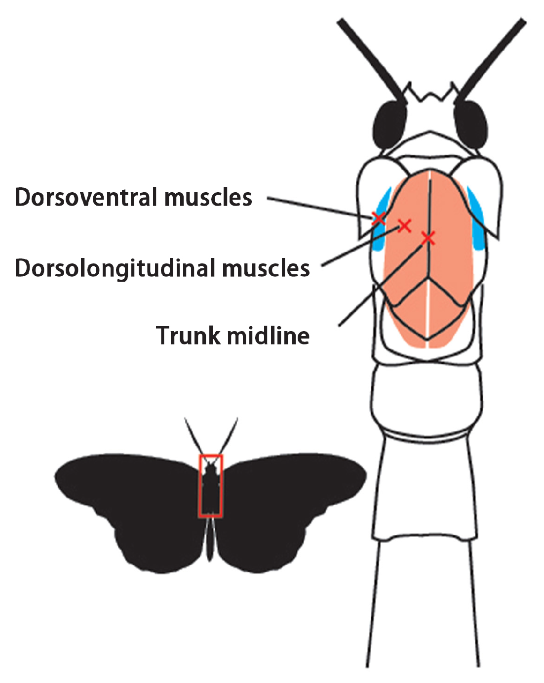
Ando et al. [16] showed that the upward and downward flapping of the wings of butterflies in flight is controlled by several groups of muscles, which are distributed as shown in Figure 1. The dorsal longitudinal muscle contracts and the dorsal abdominal muscle relaxes to produce a downbeat; the dorsal abdominal muscle contracts and the dorsal longitudinal muscle relaxes to produce an upturn of the wings.
Butterflies rely mainly on the drag force on the wings to provide lift and thrust during flight [17]. When the wings are flapping down, a strong “vortex ring” will be generated, which is a combination of leading edge vortex, wing end vortex, and starting vortex, and a jet will be generated [18], and the reaction force of this jet is the resistance of the wings to provide lift for flight. When the butterfly wings are flipped up, due to the existence of an angle of attack of the butterfly’s body at this time, the resistance of the wings will provide the thrust for flight at this time.

2.2. The Design of the Driving Mechanism of the Wing-Fluttering Machine

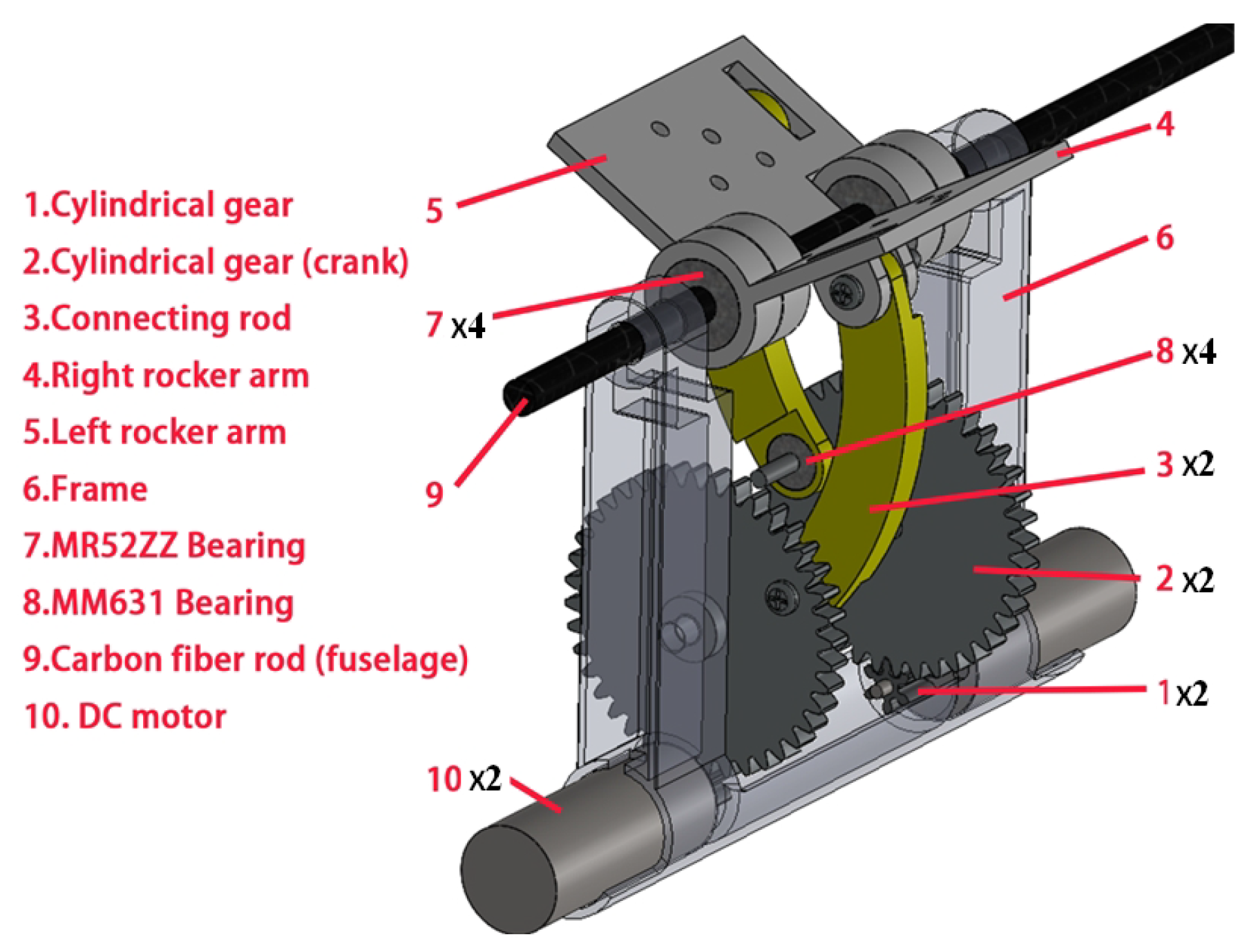
Based on the fact that the butterfly’s wings and trunk are connected to the back, and the muscles are mainly distributed in the trunk, the design of the wing-fluttering drive mechanism is shown in Figure 2.
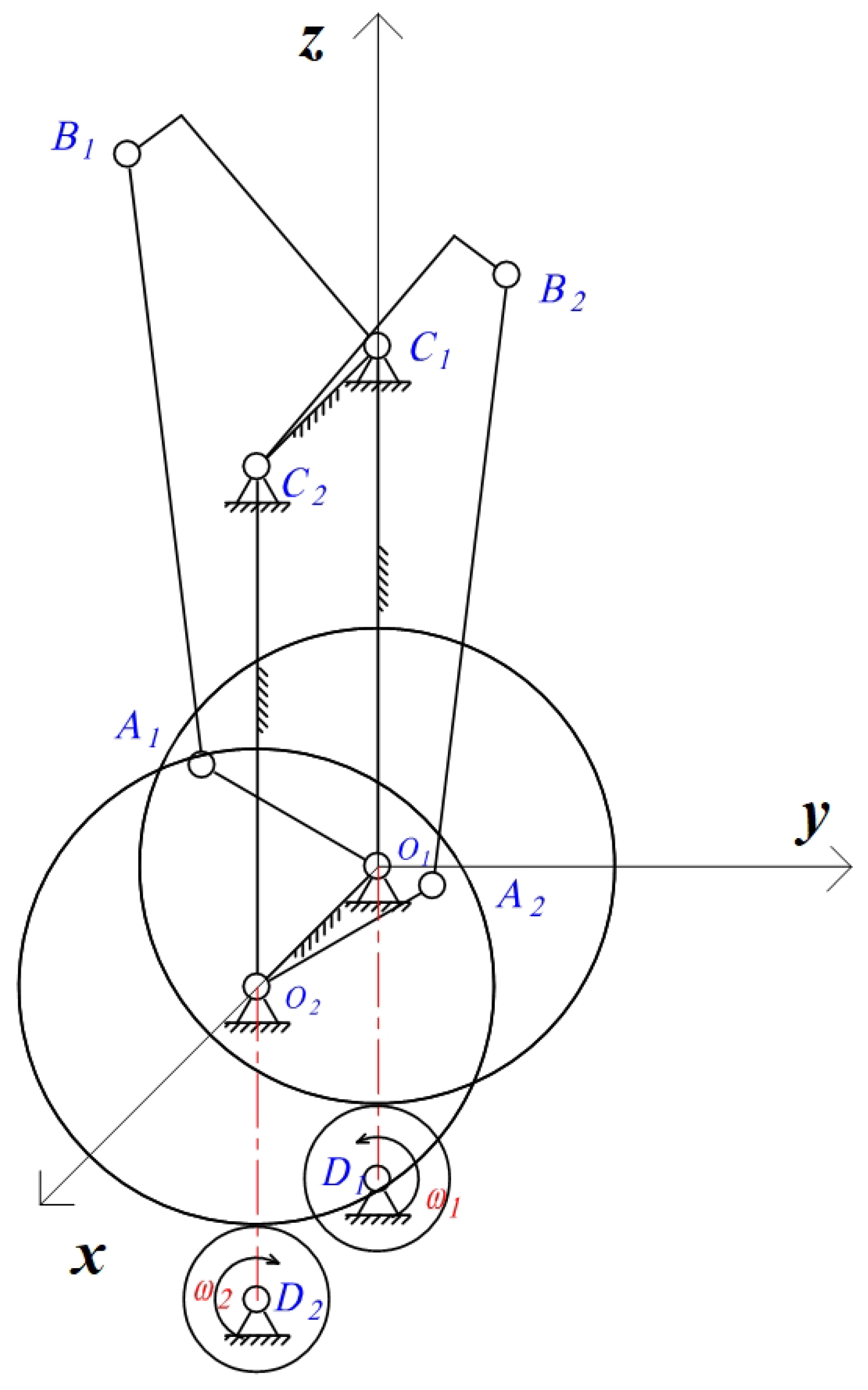
The rocker connecting the wings of this mechanism is matched with the carbon rod of the fuselage through bearings. Using the motion characteristics of the crank–rocker mechanism, the distance between the rotation center of the crank and the connecting point of the connecting rod and the rocker will change periodically to simulate the contraction and relaxation of the muscles of butterflies in flight. The mechanical principle is shown in Figure 3.
In the figure above, two small cylindrical gears are driven by two DC motors to rotate around the axes of D 1 and D 2 . Two large cylindrical gears, which act as cranks, are driven to rotate around the axes of O 1 and O 2 . The connecting rods, A 1 B 1 and A 2 B 2 , are fixed to the two cylindrical gears by bearings and screws, following the gears to perform planar motion. Then, the rods C 1 B 1 and C 2 B 2 are driven to perform planar motion around the axes of C 1 and C 2 . Subsequently, the rods C 1 and C 2 rotate around the axes of C 1 and C 2 . This mechanism has advantages such as its simple structure, compactness, light weight, facilitation of individual control of the left and right wing frequencies, greater flexibility, low cost, etc.

2.3. Selection of Wing Type

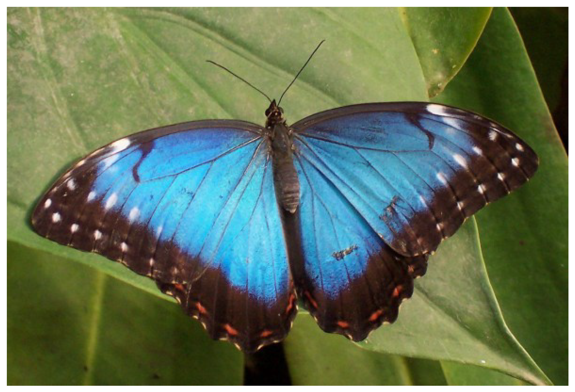
The Morpho peleides was chosen as the bionic object, whose shape parameter is closer to the average value of most butterflies, and the ratio of the wing to the body weight is smaller, so the efficiency of lift generation is higher, as shown in Figure 4.
The design target size is defined as the size of a micro-air vehicle with low Reynolds number aerodynamic characteristics [19,20]. The black solid line in Figure 5 shows the wing size of the high-performance bionic butterfly designed in this paper; the blue dotted line is the wing size of the bionic butterfly chosen by Ye [21,22], who used a double-rudder flap drive mechanism, and the red dotted line is the wing size of the bionic butterfly chosen by Huang [23], who used a double crank and double-rocker drive mechanism. The airfoil dimensions were determined for a bionic butterfly flying machine equipped with a double-crank and double-rocker flapping drive mechanism. The selected airfoil has a spread length of R = 0.1475 m, a spread chord ratio of λ = 1.11 , and a mean chord length of c = 0.115 m. The area of the airfoil is greatly reduced compared to the one mentioned in the previous section.
Based on the butterfly’s wing support structure, the wing of the bionic butterfly aircraft is designed, which mainly consists of three parts—the wing strut, the wing rib, and the aircraft skin—as shown in Figure 6. In order to ensure a light weight and high tensile strength [24], 3D-printed nylon PA12 is used as the structural material for the wing struts. P43n kite cloth and pet film are used as the wing skin material, and carbon fibre rods are used as the material for the wing veins, which are fixed with 403 glue.

2.4. The Design Process of the High-Performance Bionic Butterfly Prototype

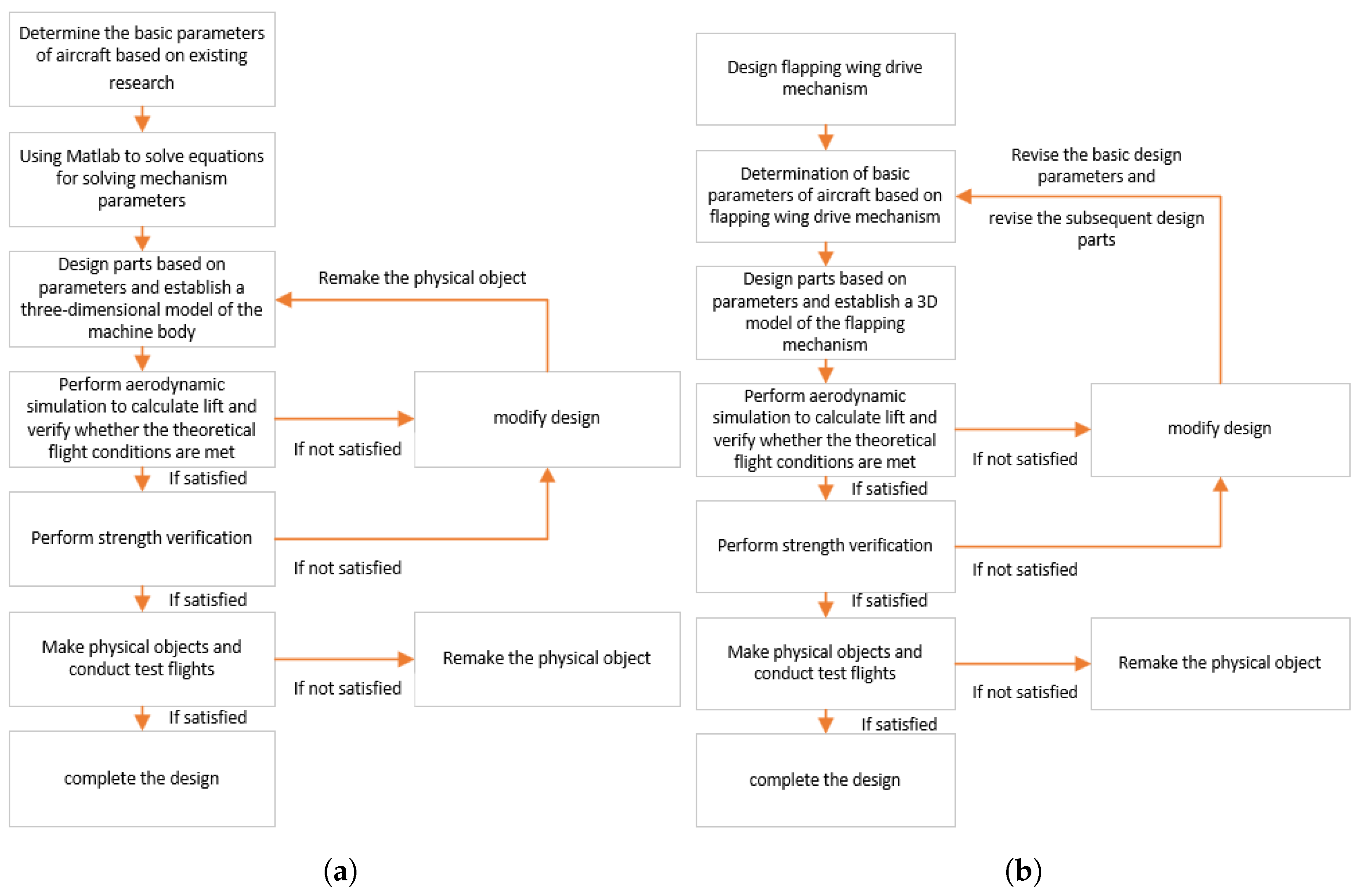
The design process of the high-performance bionic butterfly differs from that of traditional flapping-wing vehicles, primarily in the initial design premises. Key parameters [25], such as wing-flapping amplitude, ratio of upstroke to downstroke distribution, flight pitch angle, and speed, are derived based on bionic scaling effects [26]. These parameters then inform the design of the flapping-wing drive mechanism, as illustrated in Figure 7a. In contrast, the conventional design process for traditional flapping-wing vehicles [27], shown in Figure 7b, begins with the development of the flapping drive mechanism. The kinematic characteristics of this mechanism are subsequently used to determine the basic aerodynamic and structural parameters of the wing.
In the traditional flapping wing design process, since the design of the flapping-wing drive mechanism has already been determined, if there is a problem of insufficient lift in the subsequent design, we can only increase the area of the wing in order to increase the lift, which is not convenient for controlling the mass and volume. However, the prototype design process described in this paper is based on fixing the basic parameters and optimizing the structural design, which ensures that the final optimized design of the flapping wing has a similar volume and mass as the initial target [28].

2.5. Control System Design

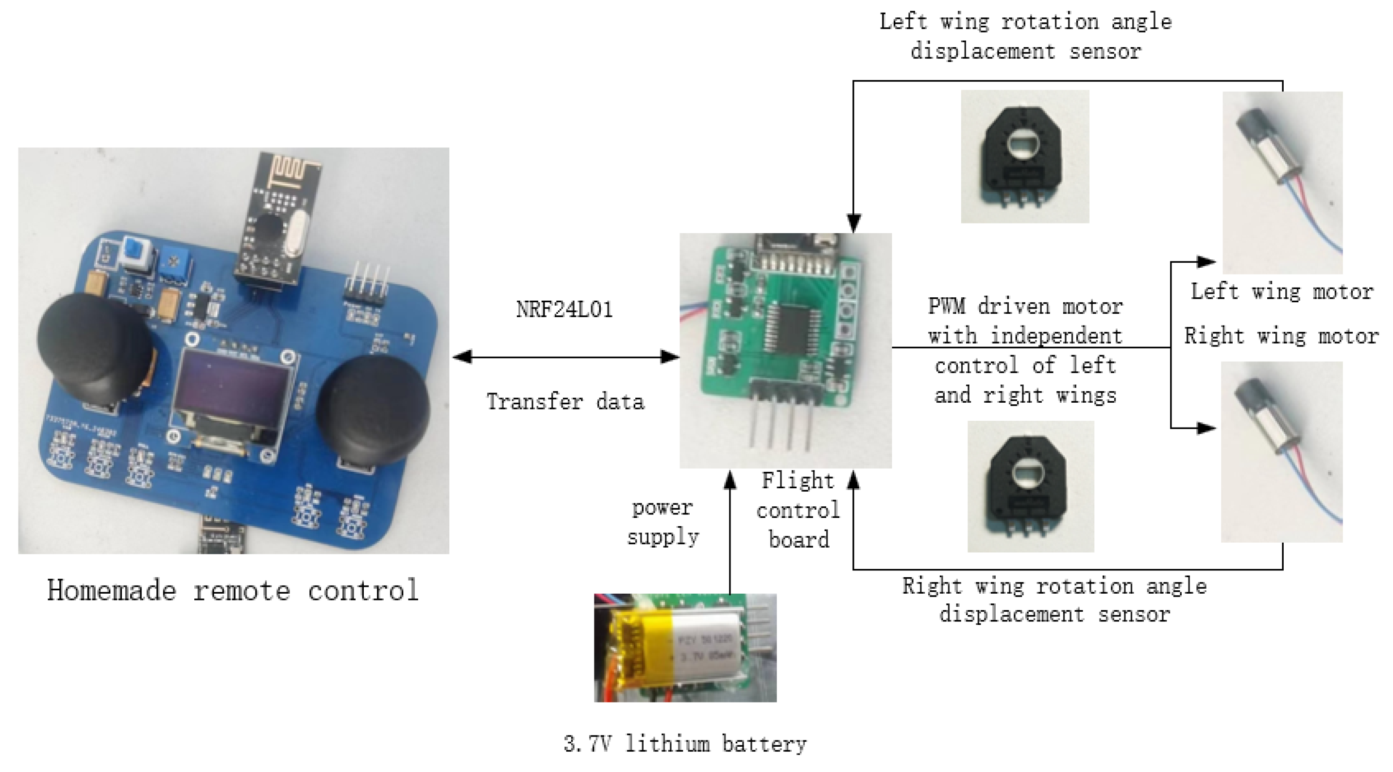
The home-made flight circuit board uses STC15W408S (Shenzhen JLC Technology Group Co., Ltd., Shenzhen, China) as the main control chip, with built-in crystal and SPI and PWM functions. We select NRF24L01 as the remote control receiver, and use STC15W408S, which through SPI communication, can be used to control the motor (Wuhan Wuxiu Technology Co., Ltd., Wuhan, China). There is also a lithium battery directly responsible for the motor and STC15W408S power supply. The use of RT9013-3.3V (Shenzhen JLC Technology Group Co., Ltd., Shenzhen, China) will provide enough power (voltage 3.3 V) to supply NRF24L01, through the N-channel FETs, to build the motor drive circuit. We also use PWM waves to switch the FETs on and off, in order to control the motor switch and speed. The H-bridge controls the motor switch and speed and changes the voltage direction, while the rotary angle displacement sensor is used to ensure that the two wings beat at the same frequency. The control system is as shown in Figure 8.
The various components of the bionic butterfly flapping-wing aerial vehicle are closely related to energy consumption. The flapping-wing mechanism is the primary source of energy consumption, as it must continuously overcome air resistance and its own inertial forces to generate lift and thrust. Significant efficiency losses occur in the motor due to high-speed reciprocating motion, accounting for over 90% of the total energy usage. The control system contributes to a relatively stable and small portion of the basic static energy consumption, while the communication system consumes even less power.

3. Structural Analysis of a High-Performance Biomimetic Butterfly Flyer

3.1. Determination of the Degrees of Freedom of the Flapping Wing Drive Mechanism

Since the mechanism is center-symmetric, the topological space of the right wing drive mechanism can be taken as the research object, according to the Kutzbach–Grubler degree of freedom formula, which is as follows:
D o F = m ( N 1 J ) + i = 1 J f i
Under the condition that all joint constraints are independent, for a mechanism consisting of (N) components (including the base), let (J) denote the number of kinematic pairs, (m) the degrees of freedom of a rigid body (with m = 3 for planar mechanisms and m = 6 for spatial mechanisms), and f i the degrees of freedom associated with the (i)-th kinematic pair. In this mechanism, since points O 2 A 2 B 2 C 2 move within the same plane, we have J = 4 , N = 4 , m = 3 , and i = 1 J f i = 4 . Therefore, the degrees of freedom of this flapping-wing drive mechanism can be calculated as
D o F = 3 ( N 1 j ) + i = 1 j f j = 3 × ( 4 4 1 ) + 4 = 1
Therefore, the degree of freedom of the flap drive is 1. Therefore, the motion of the right flap drive mechanism can be determined by a single DC motor drive.

3.2. Flap Drive Mechanism Modelling

3.2.1. Five-Bar Mechanism Modelling

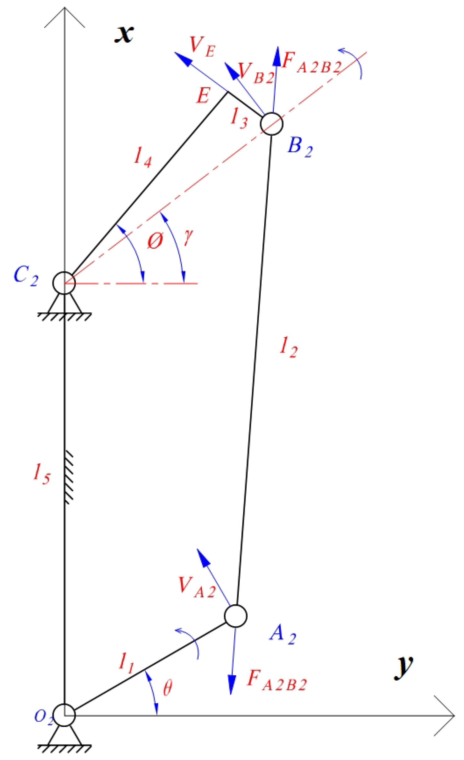
The right-wing drive mechanism is projected onto the y O 2 plane. Taking the crank rotation axis o 2 as the origin of the coordinate system, the frame direction O C 2 is defined as the z-axis, and the direction perpendicular to the z-axis intersecting at point O 2 is defined as the y-axis, thereby establishing a planar rectangular coordinate system, as shown in Figure 9.
Let the length of the crank O 2 A 2 be l 1 , the length of the connecting rod A 2 B 2 be l 2 , and the right-angled bent rod act as the rocker, with the right-angle vertex designated as E. The length B E is l 3 , the length E C 2 is l 4 , and O 2 C 2 is l 5 . The crank rotation angle is θ , the rocker rotation angle is φ , and the angle between the line C 2 B 2 and the y-axis is γ .
Based on the planar rectangular coordinate system established in Figure 8, the right-wing drive mechanism is placed within this coordinate system, and by defining the lengths of the respective rods, the coordinates of each point can be determined as follows: O 2 ( 0 , 0 ) , A ( l 1 · c o s θ , l 1 · s i n θ ) , B ( c o s γ · l 3 2 + l 4 2 , l 5 + s i n γ · l 3 2 + l 4 2 ) , C ( 0 , l 5 ) , E ( l 4 · c o s φ , l 5 + l 4 · s i n φ ) . The relationship between angle γ and angle φ is given by
γ = φ arctan l 3 l 4
Using the method of kinematic chain decomposition [29,30], the relationship between the crank rotation angle θ and the rocker rotation angle φ is established. Based on the geometric constraints of the right-angled bent rod C 2 E B 2 and the link A 2 O 2 , the motion constraint equation of the connecting rod A 2 B 2 can be derived as
( y b y a ) 2 + ( z b z a ) 2 = l 2 2
By substituting the horizontal and vertical coordinates of points B 2 and A 2 , listed above, into the motion constraint equation of the connecting rod and then solving the resulting system of equations through elimination and simplification, an expression for φ as a function of the lengths of the rods and the angle θ can be obtained.
φ = arctan 2 A ± 4 A 2 4 B C 2 B
The expressions for A, B, and C are as follows:
A = l 3 l 5 l 4 l 1 cos θ B = l 3 2 + l 4 2 C = l 5 2 + l 1 2 2 l 1 l 5 cos θ l 2 2

3.2.2. Sensitivity Analysis of Rod Length on Key Parameters of a Five-Bar Mechanism

Based on the relationship between the rocker angle φ and the crank rotation angle θ derived in Section 3.2.1, a sensitivity analysis was conducted on the rod lengths with respect to the designed five-bar mechanism’s motion range, motion smoothness, and mass characteristics. A set of parameters satisfying the formation conditions of the designed five-bar mechanism was selected for the nominal parameters, as listed in Table 1.
The One Factor at a Time (OFAT) method was employed. Rods from O 2 A 2 to C 2 O 2 were sequentially selected as the variables for analysis. Based on a certain percentage of nominal values, a reasonable length variation range [ l min , l max ] was set for each variable, with ±15% chosen to avoid potential singularities or computational difficulties and to ensure that the rod lengths remain positive. Within each length variation range, six sampling points were selected as test points for sensitivity analysis of the respective rods. The corresponding plots are shown in Figure 10a–e.
Based on the analysis of the result graphs, it is evident that increasing the length of the O 2 A 2 rod amplifies the amplitude of the curve, thereby increasing both the upper and lower limit angles of the E C 2 rod’s motion. Increasing the lengths of the A 2 B 2 and C 2 O 2 rods causes the entire curve to shift upward, which increases the upper limit angle and decreases the lower limit angle of the E C 2 rod’s motion. Increasing the length of the B 2 E rod results in a slight upward shift of the curve, slightly increasing the upper limit angle and decreasing the lower limit angle of the E C 2 rod’s motion. Increasing the length of the E C 2 rod significantly raises the peak value of the curve and slightly elevates the trough value, increasing the upper limit angle and slightly increasing the lower limit angle of the E C 2 rod’s motion.
The absolute peak value of the angular acceleration of joystick E C 2 is selected as the core metric for evaluating motion smoothness. A smaller value of this metric indicates smoother joystick movement with less impact. With the crank rotation frequency set to 6 Hz, the lengths of the individual links are varied sequentially for analysis. The results are shown in Figure 10f.
Increasing the lengths of the O 2 A 2 rod and the A 2 B 2 rod will increase the absolute peak value of angular acceleration, thereby reducing motion smoothness. Increasing the lengths of the E C 2 rod and the C 2 O 2 rod will decrease the absolute peak value of angular acceleration, also reducing motion smoothness. Changes in the length of E C 2 have almost no effect on the absolute peak value of angular acceleration, with motion smoothness remaining nearly unchanged.
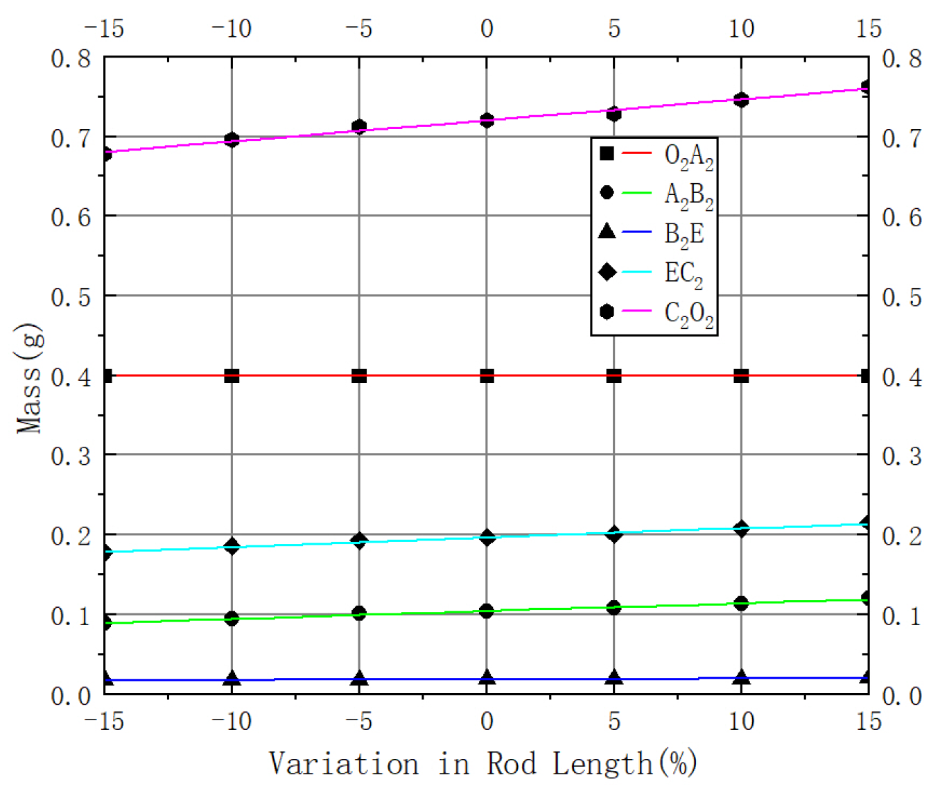
Due to the varying shapes of the rods, the lengths of each component were modified in SOLIDWORKS software to obtain the mass of the components at different rod lengths. The fitted graph is shown in Figure 11.
The functional curves of mass with respect to changes in rod length in the image are shown in Table 2.

3.3. Optimization of Rod Length Selection for Flapping-Wing Drive Mechanism

An improved method based on the optimization of four-bar mechanisms used in reference [31] is applied to a five-bar mechanism. A multi-objective optimization of the designed flapping-wing drive five-bar mechanism is carried out using a genetic algorithm (NSGA-II).
According to existing research [32], when the flapping angle of the butterfly wings is 90°, and the angle distribution between the wingbeats below and above the plane of the body is 1:2, the biomimetic butterfly can achieve better flight performance. At this point, the lower limit angle of the wingbeat displacement should be 30°, and the upper limit angle should be 60°, with the average flapping frequency being 6 Hz. The optimization objectives are determined as follows:
  • The range of motion of joystick E C 2 should be as close to 90° as possible in the positive direction.
  • The ratio of the absolute values of the upper and lower limit angles during the motion of joystick E C 2 should be close to 2.
  • We maximize the smoothness of joystick E C 2 motion.
  • We minimize the mass of the five-bar mechanism.
The objective function f 1 ( x ) of optimization objective 1 is shown in Equation (7). The actual maximum range of motion is obtained by subtracting the lower limit deviation φ min from the upper limit deviation φ max . The actual calculation is the absolute difference between the maximum motion range and the target of 90°. The smaller the value, the closer the upper limit deviation is to 90°.
f 1 ( x ) = φ max φ min π 2
The objective function f 2 ( x ) of optimization objective 2 calculates the difference between the absolute value of the upper limit deviation | φ max | and twice the absolute value of the lower limit deviation 2 · | φ min | . The smaller the value, the closer the ratio of the two values is to 2, as shown in Equation (8). This approach is more stable when φ min approaches 0.
f 2 ( x ) = | | φ max | 2 · | φ min | |
The objective function f 3 ( x ) for optimization objective 3 is shown in Equation (9), where the absolute value of the peak angular acceleration is used to evaluate the smoothness of joystick motion. The smaller the value, the less impact and the smoother the motion.
f 3 ( x ) = | φ ¨ max |
The objective function f 4 ( x ) for optimization objective 4 is shown in Equation (10), where the total mass of all the rods is calculated based on the fitting results in Table 2. The smaller the value, the lighter the mechanism.
f 4 ( x ) = y 1 + y 2 + y 3 + y 4 + y 5
In summary, the multi-objective optimization function for the designed mechanism is shown in Equation (11).
f 1 ( x ) f 2 ( x ) f 3 ( x ) f 4 ( x )
In the above equation, x = [ l 1 , l 2 , l 3 , l 4 , l 5 ] ; the value ranges for each parameter are determined based on the parts required for the mechanism to function properly. To ensure the values are strictly greater than the constraint conditions, a small positive number ϵ is introduced: Crank O 2 A 2 rod length l 1 [ 4.0 + ϵ , 8 ] , link 1 A 2 B 2 rod length l 2 [ 12.0 + ϵ , 20 ] , link 2 B 2 E rod length l 3 [ 1 + ϵ , 4 ] , joystick E C 2 rod length l 4 [ 5 + ϵ , 10 ] , frame C 2 O 2 rod length l 5 [ 12.0 + ϵ , 20 ] .
The parameters used in the genetic algorithm are shown in Table 3.
The output of NSGA-II is the first non-dominated front in the final generation of the population. Priority is given to ensuring that the motion range and distribution ratio of the joystick meet the requirements. The final selected optimization results are shown in Table 4.

3.4. Flapping Actuation Mechanism Motion Range Optimization Result Analysis

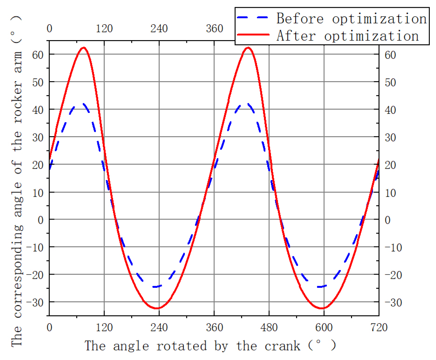
By inputting the parameters from Table 1 and Table 4 into MATLAB software, the change in angle φ of the rocker was calculated during two complete crank cycles. For crank angle θ rotating across 720°, the corresponding angular displacement variations are shown in Figure 12, depicting the crank–rocker mechanism’s angular displacement.
From Figure 12, it can be seen that with the optimized parameters applied in manufacturing the crank–rocker mechanism, within one cycle, the rocker attains a lower extreme angular displacement of −31.27° and an upper extreme of 62.37°, resulting in a flapping amplitude of 93.64°. The deviation from the design target amplitude of 90° was reduced from 25.54% before optimization to 4.12%; likewise, deviation in the flapping distribution ratio from the target value of 2 was reduced from 13.31% to 0.35%. Thus, the optimization results with respect to both design objectives are excellent.

3.5. Analysis of Motion Smoothness in the Optimization Results of the Flapping Wing Drive Mechanism

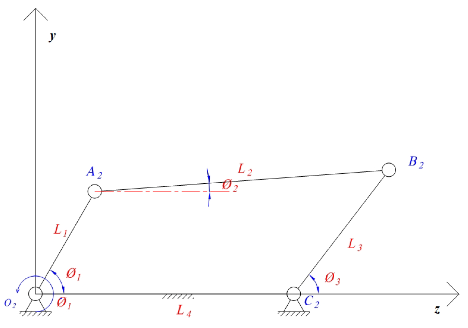
Since Equations (3)–(6) are too complex for simultaneous differentiation, the mechanism is simplified by replacing the right-angle bent link C 2 E 2 B 2 with a rigid rod C 2 B 2 . The simplified four-bar mechanism undergoes a coordinate transformation, and all variables are renamed accordingly. The link components are designated as L 1 , L 2 , L 3 , and L 4 . The angular displacement of the driver O 2 A 2 is φ 1 , with a constant angular velocity of φ ˙ 1 . The angular displacement of the link A 2 B 2 is φ 2 , with angular velocity φ ˙ 2 . The angular displacement of the rocker B 2 C 2 is φ 3 , with angular velocity φ ˙ 3 , as illustrated in Figure 13.
Based on the method for studying angular velocity of linkages presented in reference [33], by differentiating the independent motion equations of planar hinged four-bar mechanisms with respect to time, the expression for output velocity can generally be represented in matrix form as follows:
U ˙ = F U 1 F V V ˙
In the above equation, V = [ v 1 , v 2 , , v λ ] T represents the generalized input motions of the mechanism; U = [ u 1 , u 2 , , u n ] T denotes the generalized output motions of the mechanism; and F = [ f 1 , f 2 , , f n ] r corresponds to the n-independent motion equations.
The following expressions are given for φ 2 and φ 3 :
φ 3 = 2 arctan A + M A 2 + B 2 C 2 B C φ 2 = 2 arctan D + M D 2 + E 2 F 2 E F
When points A 2 , B 2 , and C 2 are arranged in a clockwise direction, let M = 1 ; the parameters in the equation are as follows:
A = 2 L 1 L 3 s i n φ 1 B = 2 L 3 ( L 1 c o s φ 1 L 4 ) C = L 2 2 L 1 2 L 3 2 L 4 2 + 2 L 1 L 4 c o s φ 1 D = 2 L 1 L 2 sin φ 1 E = 2 L 2 ( L 1 cos φ 1 L 4 ) F = L 1 2 + L 2 2 L 3 2 + L 4 2 2 L 1 L 4 cos φ 1
By substituting the expressions from Equations (13) and (14) into Equation (12), the angular displacements φ 2 and φ 3 corresponding to a given φ 1 at a certain moment can be solved. Let C i = L i cos φ i and S i = L i sin φ i ; then,
φ ˙ 2 φ ˙ 3 = 1 S 2 C 3 C 2 S 3 C 3 S 3 C 2 S 2 S 1 C 1 [ φ ˙ 1 ]
By substituting the parameters from Table 1 and Table 4 and the average flapping frequency of butterfly wings during flight into the expression, the angular velocity of the rocker arm over two cycles can be plotted, as shown in Figure 14.
By comparing the angular velocity curve of the rocker C 2 B 2 in Figure 14, it can be observed that, within one cycle, the curve contains one peak and one trough. The maximum upward angular velocity of the rocker C 2 B 2 increased from 4.8549 rad· s−1 before optimization to 6.5369 rad· s−1 after optimization, an increase of 34.65%. The maximum angular velocity during the downward stroke increased from 7.089 rad· s−1 to 11.4519 rad· s−1, an increase of 61.54%. This significantly enhances the aerodynamic force generated by the wing during flapping. By comparing with the motion characteristic curves of flapping-wing drive mechanisms in reference [34], we know that the motion characteristics of the rocker C 2 B 2 conform to the flapping pattern of ornithopter wings.
Differentiating Equation (12) with respect to time yields the general expression for output acceleration:
U ¨ = F U 1 d d t F U U ˙ + F V V ¨ + d d t F V V ˙
By substituting Equations (13)–(15) into Equation (16), the expression for the angular acceleration φ ¨ 3 of the rocker C 2 B 2 can be obtained:
φ ¨ 2 φ ¨ 3 = 1 S 2 C 3 C 2 S 3 C 3 S 3 C 2 S 2 φ ˙ 2 C 2 φ ˙ 3 C 3 φ ˙ 2 S 2 φ ˙ 3 S 3 φ ˙ 2 φ ˙ 3 + φ ˙ 1 C 1 φ ˙ 1 S 1 φ ˙ 1
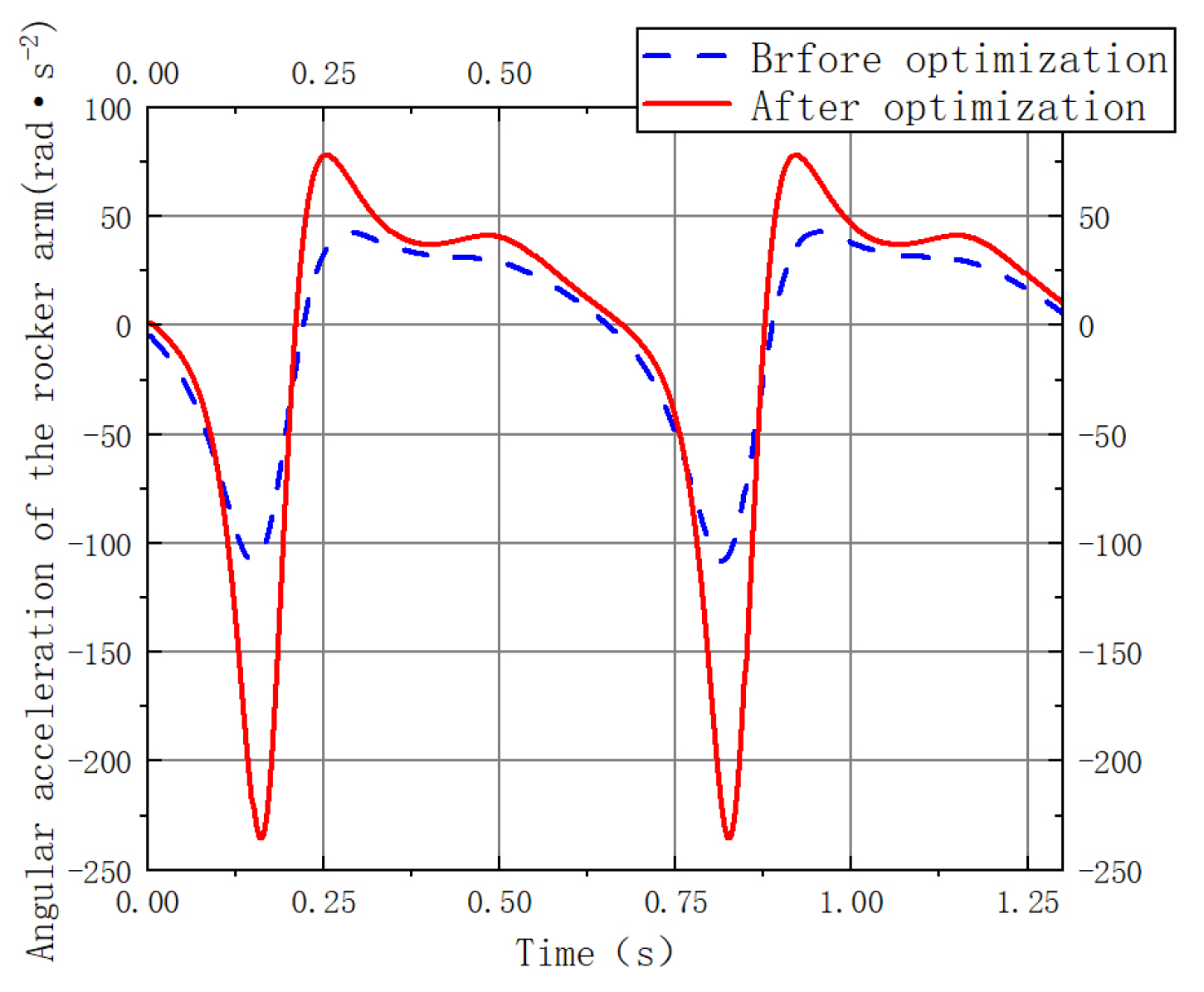
The angular acceleration curve of rocker C 2 B 2 versus time was plotted using MATLAB, as shown in Figure 15. Our analysis results reveal that optimization objectives 1, 2, and 4 increase from 107.9709 rad· s−2 to 235.5187 rad· s−2, an increase of 118.13%. Compared to the pre-optimized mechanism, the optimized design is subjected to higher inertial loads. Furthermore, although the smoothness of the angular acceleration curve decreased slightly, it remains generally continuous without abrupt transitions, indicating stable mechanical behavior and the absence of impact during flapping motion [35].

4. Dynamic Analysis and Aerodynamic Simulation

Based on the butterfly flight fluid dynamics model established by Lai et al. [36], which couples fuselage vibrations with wing flapping motion to replicate the characteristics of butterfly flight, a dynamic model of a biomimetic butterfly flyer was constructed. The reliability of the model’s computational results was verified through finite element analysis.
To simplify the model and improve computational efficiency [37], the aerodynamic model was simplified as follows: first, the direct aerodynamic effects of components such as the flapping-wing drive mechanism, battery, and fuselage were neglected. Since these components are relatively small in size and mass compared to the wing surface, the aerodynamic drag they generate can be considered negligible relative to the overall aerodynamic characteristics of the flight system [38,39,40].

4.1. Establishment of the Equations of Motion

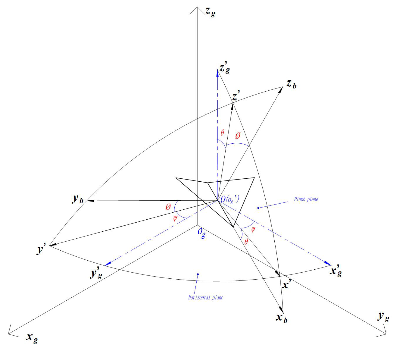
The motion is decomposed into the vehicle’s movement relative to the ground, its own pitching motion, and the reciprocating motion of the wings around the rotation center. To solve for the wing’s motion relative to the ground coordinate system, the coordinate systems are established as shown in Figure 16.
The ground coordinate system O g x g y g z g is fixed on the Earth’s surface. The origin O g is located at an arbitrarily chosen fixed point on the ground; the O g x g axis points in an arbitrarily chosen horizontal direction; the O g z g axis is vertical and points upward; and the y g axis is perpendicular to the O g x g plane and oriented according to the right-hand rule.
The body coordinate system O x b y b z b is rigidly attached to the biomimetic butterfly flyer and moves with it. Its origin is located at the center of mass of the flyer. The O x b axis lies within the symmetry plane of the flyer, parallel to the fuselage axis, and points backward; the O z b axis also lies in the symmetry plane, perpendicular to the O x b axis, and points upward; and the O y b axis is perpendicular to the symmetry plane and points to the left.
The rotation of the body coordinate system O x b y b z b relative to the ground coordinate system O g x g y g z g is represented by three Euler angles, defined as follows:
Yaw angle ψ : The angle between the projection O x of the body axis O x b onto the horizontal plane O g x g y g and the O g x g axis. A positive angle is formed when the aircraft yaws to the right.
Pitch angle θ : The angle between the body axis O x b and the horizontal plane O g x g y g . It is positive when the aircraft’s nose pitches upward.
Roll angle (bank angle) ϕ : The angle between the aircraft’s symmetry plane and the vertical plane containing the O x b axis. A positive angle is formed when the aircraft rolls to the right.
Let the coordinates of point (O) in the coordinate system O g x g y g z g be (a, b, c). First, translate point O g to O, transforming the two three-dimensional coordinate systems O x b y b z b and O g x g y g z g to ensure they coincide. The transformation relationship between them can be expressed as
x b y b z b = L b g x g a y g b z g c
In this equation,
L b g = cos θ cos ψ cos θ sin ψ sin θ sin θ sin ϕ cos ψ cos ϕ sin ψ sin θ sin ϕ + cos ϕ cos ψ sin ϕ cos θ sin θ cos ϕ cos ψ + sin ϕ sin ψ sin θ cos ϕ sin ψ sin ϕ cos ψ cos ϕ cos θ
The motion of the biomimetic butterfly flyer during level flight is analyzed by assuming that the yaw angle ψ , roll angle (bank angle) φ , and yaw displacement (b) are all zero. Based on computational studies by experts on butterfly flight characteristics [41,42,43,44]—and by substituting the biomimetic butterfly flyer parameters, including wingspan R = 0.1475 m, aspect ratio λ = 1.11 , mean chord length c = 0.0845 m, and wing flapping frequency f = 1 T = 6 Hz—the pitch angle θ is calculated as θ = 5 + | 45 · sin ( 2 π T · t ) | , while average velocity v = 0.5 m/s, horizontal displacement a = t , and vertical displacement c = | 0.1 · sin ( π T · t ) | . These parameters closely match the body and wing motion parameters observed by Dudley [45] during free cruising flight of butterflies.
By substituting θ , v , a , c , and the time-varying wing velocity function obtained in Section 2.3 into Equation (18), the position of the centroid of one wing as a function of time t can be inversely solved:
x o w y o w z o w = L b g t 0.057 · cos ( 42.5 · sin 2 π T · t ) 0.057 · ( 5 + 45 · sin 2 π T · t ) · cos ( 42.5 · sin 2 π T · t )

4.2. Establishment of the Aerodynamic Model

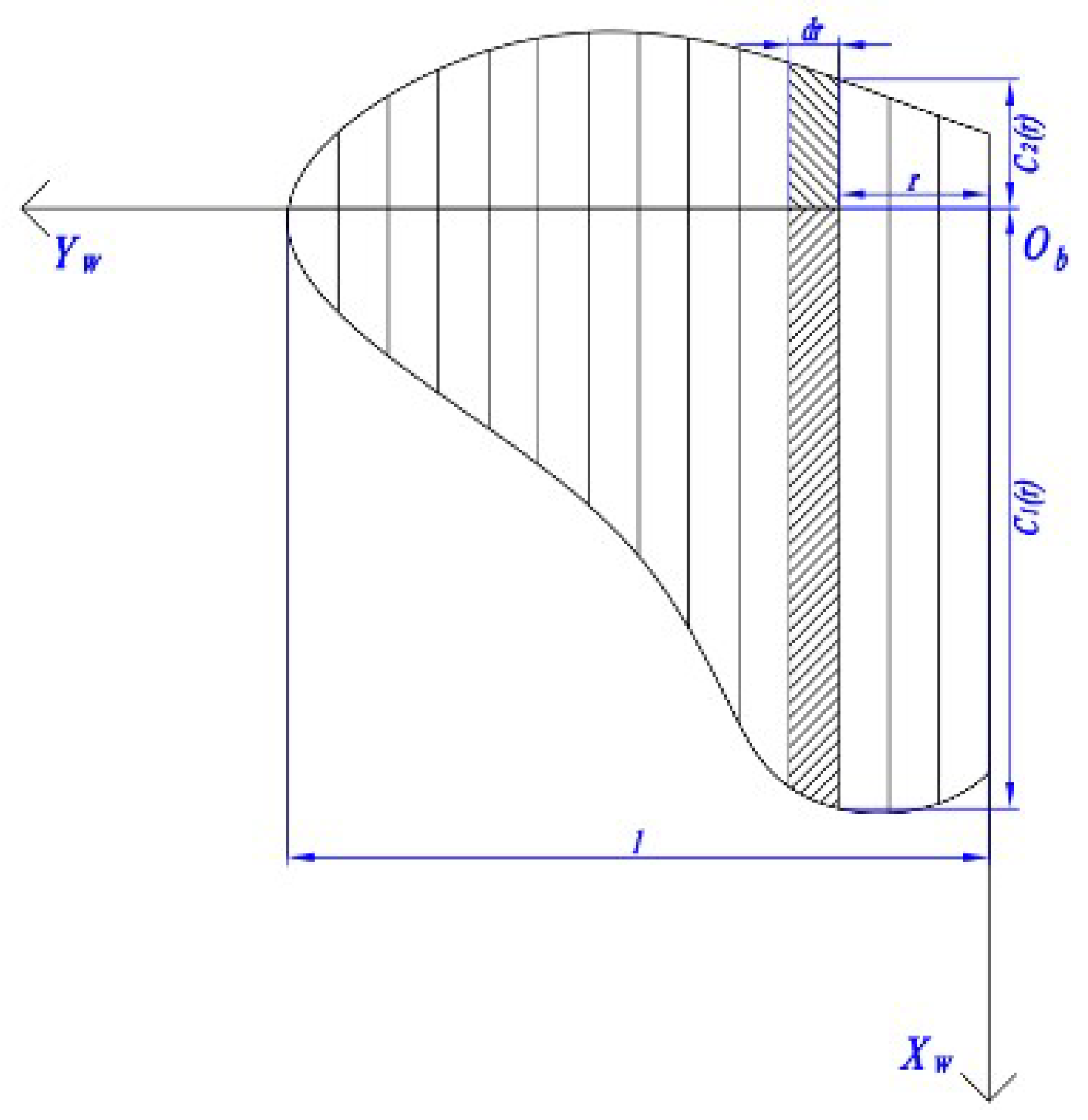
A dynamic model of the biomimetic butterfly was established using the dynamic modeling approach for insect flapping flight proposed by Luca [46,47]. To this end, a wing plane coordinate system O w x w y w is introduced, and the wing is discretized, as shown in Figure 17. For the analysis of the left wing, the aerodynamic forces on each wing element are examined:
Let the angular velocity vector of the wing be u = ( ξ ˙ , 0 , ζ ˙ ) , where ξ and ζ are the flapping and flipping angles of the wing at time (t); the velocity vector of the flyer is v = ( v x g , v y g , v z g ) ; the attitude vector of the flyer is w = ( ψ , θ , ϕ ) ; (r) is the distance from each wing element to the O w Y w axis; C 1 ( r ) and C 2 ( r ) are the chord lengths along the negative and positive directions of the O w Y w axis, respectively; ρ is the air density; and U is the velocity of the wing element surface relative to the airflow, as given in Equation (20).
U = d ζ ˙ sin ζ ξ ζ ˙ cos ζ sin ξ ξ ξ ˙ sin ζ cos ξ + v χ g d ζ ˙ cos ζ + v y g d ζ ˙ cos ζ ξ ζ ˙ sin ζ sin ξ + ξ ξ ˙ cos ζ cos ξ + v z g
The aerodynamic force on each wing element can be expressed as Equation (21):
d F zw = 1 2 c zb ( u , v , w ) ρ U 2 c ( r ) d r d F xw = 1 2 c xb ( u , v , w ) ρ U 2 c ( r ) d r
In the equation, d F z b and d F x b represent the aerodynamic force components on the wing element perpendicular to the wing plane and parallel to the wing plane along the chordwise direction, respectively; c z w and c x w are the aerodynamic coefficients in the normal and chordwise directions of the wing. According to Dickinson [48], the aerodynamic coefficients obtained by experimental fitting are given by Equation (22):
C z w ( α ) = 0.225 + 1.58 sin ( 2.13 α 7.20 ) C x w ( α ) = 1.92 1.55 cos ( 2.04 α 9.82 )
In the equation, α = cos 1 O w X w ¯ · u | U | is the angle between the chord direction and the airflow during the wing flapping process.
By integrating the aerodynamic force expressions over the wing elements, Equations (23) and (24) can be obtained:
F xw = 1 2 c xw ( u , v , w ) ρ U 2 S
F zw = 1 2 c zw ( u , v , w ) ρ U 2 S
In the equations, F zw and F xw represent the lift and thrust components of the aerodynamic force in the wing plane coordinate system; S denotes the wing area. The forces transformed into the body coordinate system can be expressed as Equation (25), and those in the ground coordinate system can be expressed as Equation (26):
F b = L wb ( F yW , F XW , F ZW ) T
F g = L bg L wb ( F yW , F XW , F ZW ) T
In the above equation,
L w b = cos ξ 0 sin ξ sin ζ sin ξ 0 cos ξ cos ζ 0 sin ζ sin ζ
Thus, the aerodynamic force curves experienced by the biomimetic butterfly flyer during flight can be calculated using MATLAB software.

4.3. Aerodynamic Simulation

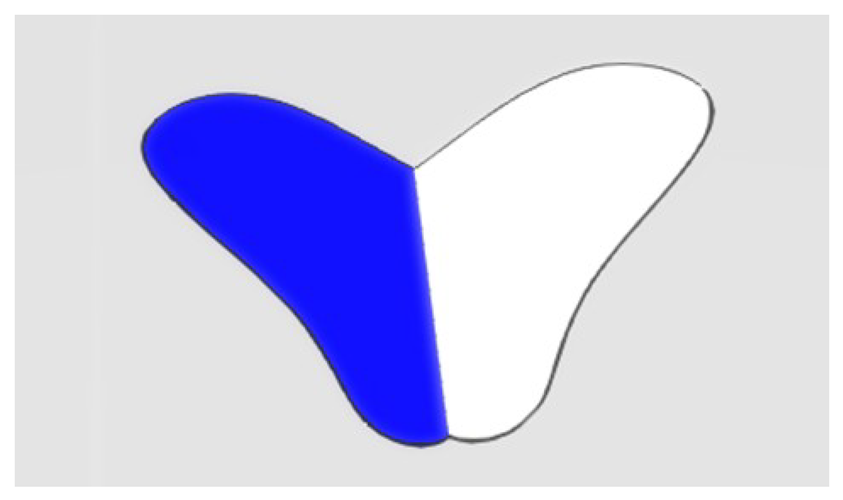
The simplified aerodynamic calculation model of the biomimetic butterfly flapping-wing flyer is shown in Figure 18. The wingspan of the butterfly aerodynamic model is approximately 0.295 m, and the fuselage length is about 0.161 m.
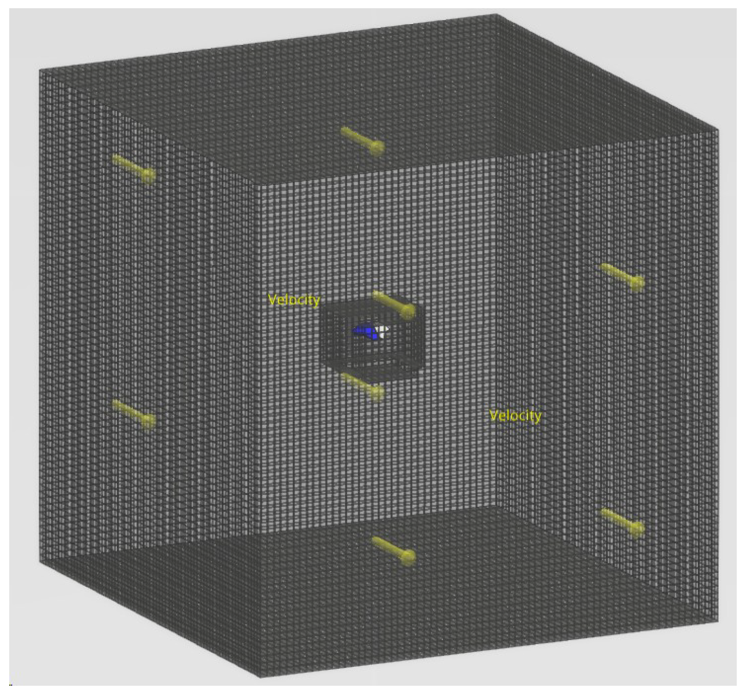
Xflow software was used to perform aerodynamic simulations of the biomimetic butterfly flyer. Based on the Smoothed Particle Hydrodynamics (SPH) method, the fluid is discretized into particles, and the fluid motion and physical behavior are simulated using kernel function interpolation and explicit time-stepping methods. To reduce computational load, shorten calculation time, and ensure millimeter-level computational accuracy, the numerical wind tunnel domain dimensions (length, width, and height) were set to ten times the maximum length direction [49].
The flow field mesh is divided using an Octree grid structure, as shown in Figure 19, with refinement applied to the wake region. The parameters of the flow field mesh are listed in Table 5.
The boundary conditions for the calculation are defined as follows:
  • Inlet Boundary Condition: The inlet is set as a velocity inlet, with an air density of 1.225 kg· m−3 and a velocity of 0.5 m· s−1.The inlet boundary generates new particles through a particle source to simulate fluid inflow. The particle generation rate at the inlet is determined by Equation (27):
    N p = m ˙ ρ · V p
    where N p is the particle generation rate, m ˙ is the mass flow rate, ρ is the fluid density, and V p is the volume of a single particle.
  • Outlet Boundary Condition: The outlet is defined as a pressure outlet with a pressure of 10,132.5 Pa. According to Equation (28), the fluid particle density within the outlet region is adjusted to ensure that the pressure equals the specified value.
    p = c s 2 ρ 0 ρ ρ 0 γ 1
    In this equation, p denotes the pressure, c s is the speed of sound, ( ρ 0 represents the reference density, ρ is the current density, and γ is the exponent in the equation of state.
  • Wall Boundary Condition: A no-slip condition is applied at the wall, implemented through a repulsive force model. Wall particles exert a repulsive force on fluid particles to prevent them from penetrating the wall. The repulsive force F wall is given by Equation (29):
    F wall = α A h 2 h r r
    where α is the repulsive force coefficient controlling the strength of the force, A is the area of the wall particle, r is the distance between the fluid particle and the wall particle, and h is the smoothing length.
According to research conducted by NASA [50], for low-speed flow field simulations, the turbulence model can employ Large Eddy Simulation (LES) combined with a Subgrid-Scale (SGS) model. By substituting the velocity field, gradient tensor g α β , trace of the velocity gradient tensor g γ γ , Kronecker δ symbol, strain rate tensor S α β , pseudo strain rate tensor G d α β , and the scale parameter Δ f = C w Δ x (where C w is the model constant and Δ x is the grid cell size) into Equation (30), the turbulent viscosity ν t is calculated. The effective viscosity ν e f f is then obtained by adding the turbulent viscosity ν t to the molecular viscosity ν . Finally, the effective viscosity is used to compute the Reynolds stress term, which is incorporated into the Navier–Stokes equations to simulate the influence of small-scale vortical structures on the flow.
ν t = Δ 2 f ( G d α β S α β S α β ) 5 2 + ( G d α β G d α β ) 3 2 ( G d α β S α β S α β ) 5 4
To improve simulation accuracy, the Wall Function is applied to handle the near-wall flow behavior, as expressed in Equation (31). Here, U is the fluid velocity, U 1 is the velocity component determined by the friction velocity u τ , U 2 is the velocity component determined by the pressure gradient velocity u p , u c is the composite velocity, and y + is the dimensionless wall distance.
U u c = U 1 u c + U 2 u p y + u p u c
The simulation time is set to 1 s, corresponding to approximately five motion cycles. The time step used in the solver is 0.001 s. Upon completion of the calculations, the velocity and pressure fields are obtained, which then allows for the determination of aerodynamic forces.

4.4. Results Analysis

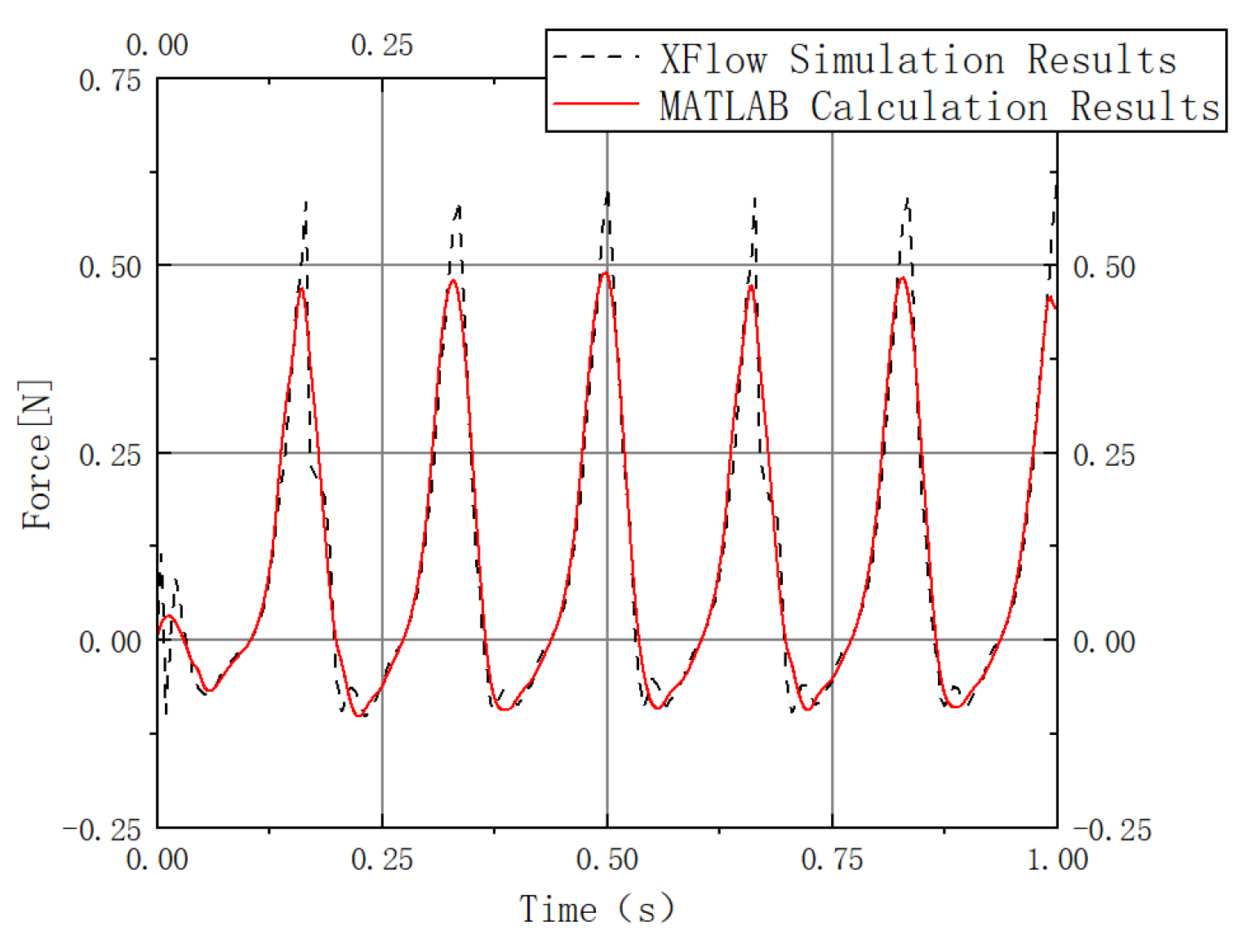
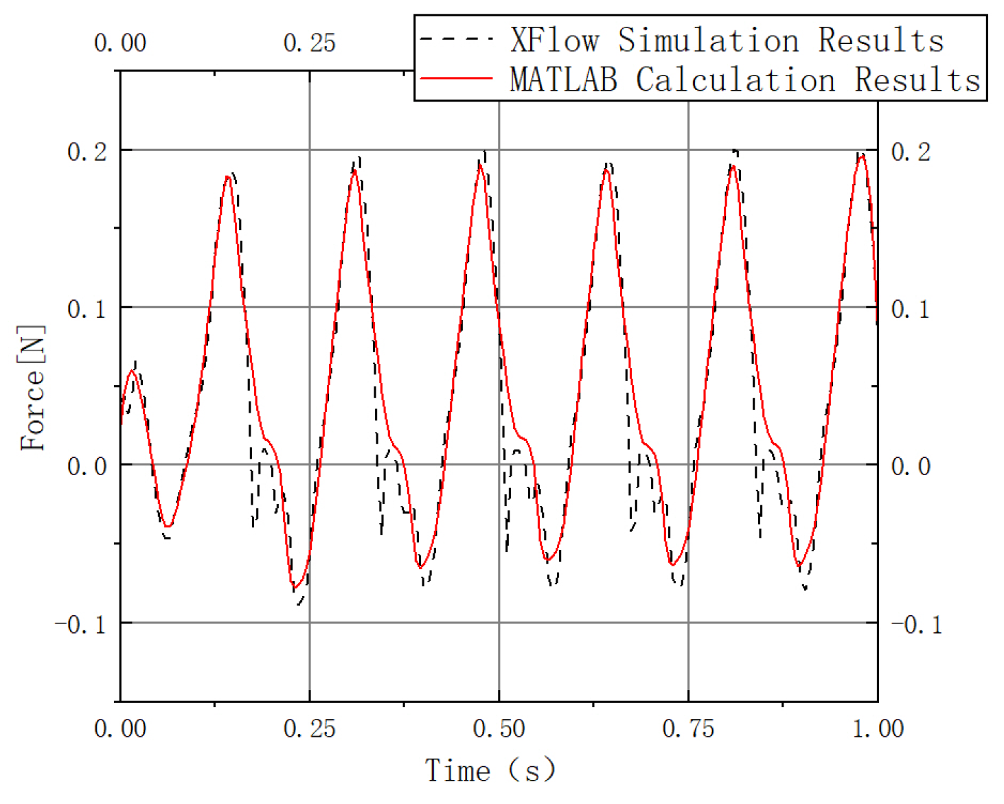
The lift calculation results are shown in Figure 20, and the thrust calculation results are presented in Figure 21.
The aerodynamic force curves in Figure 20 and Figure 21 are consistent with the aerodynamic characteristics observed during the butterfly’s forward flight [51,52,53]. The results are integrated, before being divided by the time and the number of cycles, as expressed in Equation (32).
F ¯ k = 0 t f k ( t ) t · n
In the above equation, when k = 1 , it represents the calculation of the average lift; when k = 2 , it corresponds to the calculation of the average thrust. F ¯ k denotes the average force or thrust generated by the wing during one flapping cycle; t is the upper limit of the function’s domain; and n is the number of cycles within the domain.
Using XFlow simulation, the average lift within one flapping cycle is 0.294 N, and the average thrust is 0.189 N. MATLAB calculations yield an average lift of 0.288 N and an average thrust of 0.204 N per flapping cycle. The errors in average lift and thrust are both within 5%. Moreover, the average lift exceeds the estimated weight of the biomimetic butterfly, approximately 23.5 g based on the mechanical model, indicating that it meets the requirements for normal flight.
Comparative analysis shows that the XFlow simulation results and MATLAB mathematical model are consistent in characteristics and closely aligned in numerical values. Therefore, the established model and obtained data are considered reliable, enabling subsequent sensitivity analysis.

4.5. Sensitivity Analysis

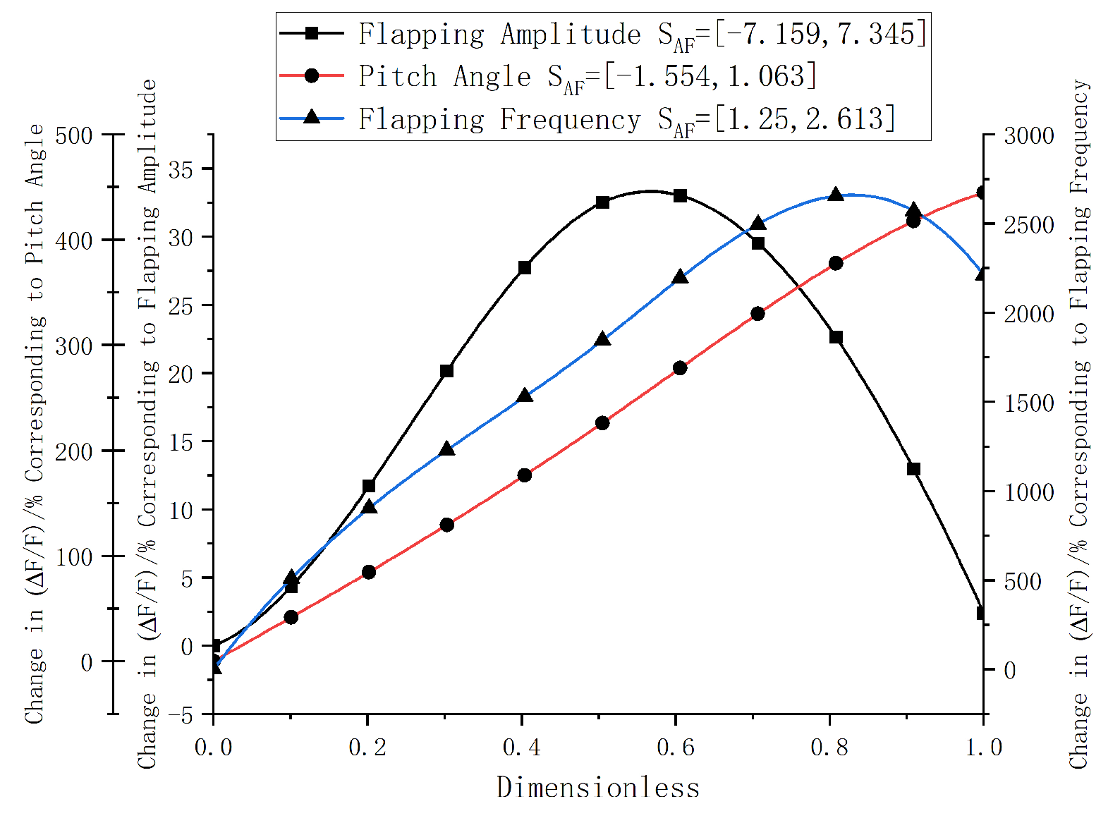
To identify the primary factors influencing lift, a sensitivity analysis of the biomimetic butterfly flapping-wing aircraft was conducted using the sensitivity factor calculation method described in reference [54]. The influencing factors are categorized into two groups: geometric parameters (such as aspect ratio and wing area) and kinematic parameters (including flapping frequency f, flapping amplitude ξ m , and pitch angle θ ). Based on the established aerodynamic model, geometric parameters were held constant, while each kinematic parameter was varied individually using the control variable method. The sensitivity factor S A F was calculated according to Equation (33) to evaluate the impact of each parameter on lift:
S A F = Δ y ( x ) / y ( x ) Δ x / x
The absolute value of S A F indicates the magnitude of the parameter’s effect on aerodynamic performance. The sign denotes the direction of influence: a positive value implies that an increase in the parameter enhances aerodynamic performance, whereas a negative value indicates a decrease. The frequency varies within the [2, 10] Hz range, the flapping angle varies within the [75°, 130°] range, and the pitch amplitude varies within the [30°, 90°] range. After normalizing the independent variables, the results are plotted in Figure 22.
At low flapping frequencies and amplitudes, lift is highly sensitive to changes in frequency and exhibits a positive correlation with flapping amplitude [55]. Increasing the flapping frequency significantly enhances lift; however, as both frequency and amplitude increase, the rate of lift growth begins to slow, eventually reaching saturation [56] and then gradually declining. In contrast, the relationship between lift and pitch amplitude shows a linear increasing trend [57], with lift continuously rising as the amplitude increases.
In summary, to achieve optimal flight performance of the aircraft, priority should be given to flapping frequency due to its largest sensitivity factor S A F . Although the sensitivity factor of flapping amplitude is smaller, the presence of saturation effects enables identification of an optimal combination of flapping amplitude and frequency. Meanwhile, the pitch angle should also be appropriately controlled.

5. Prototype Fabrication

5.1. Selection of Standard Components

Based on reference [58] and the optimized rod lengths listed in Table 4, a high-speed gear of type 8-0.8A was selected, while the low-speed gear chosen was 4010-2B. The center distance is given by m ( z 1 + z 2 ) 2 = 9.6 mm, and the transmission ratio is i = z 1 z 2 = 0.2.
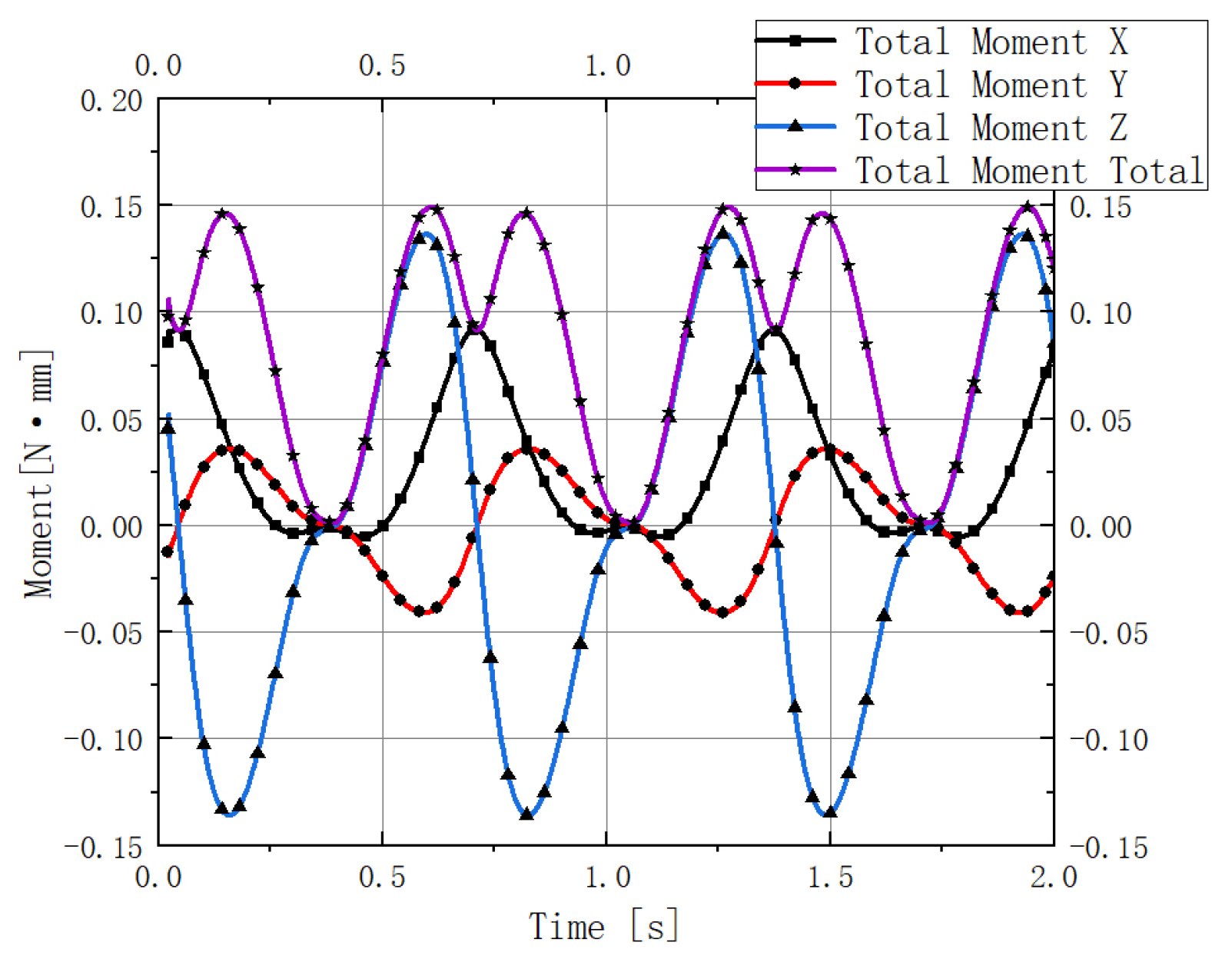
Using the Ansys joint probe, the torque exerted on the crankshaft center of the driving component O 2 A 2 during the mechanism’s motion under the aforementioned working conditions was obtained, as shown in Figure 23.
The constrained torque exhibits periodic variation because the torque that the motor must overcome is primarily generated by the aerodynamic drag acting on the wings. The torque required to overcome resistance reaches its maximum when the wings flap to the horizontal plane, as the wing’s projection onto the body coordinate system’s horizontal plane is largest at this position, resulting in the greatest drag.
When the wings are in the horizontal position, the required driving torque is approximately 0.0292 N · mm . The selected motor is a 614 brushed motor, with a rated voltage of 3.7 V, a rated output power of 2.4 W, and a rotational speed of 16,000 rpm. The maximum torque generated by this motor is calculated to be 1.435 N · mm . which satisfies the requirements for normal operation of the mechanism.

5.2. Manufacturing of Non-Standard Components and Prototype Assembly

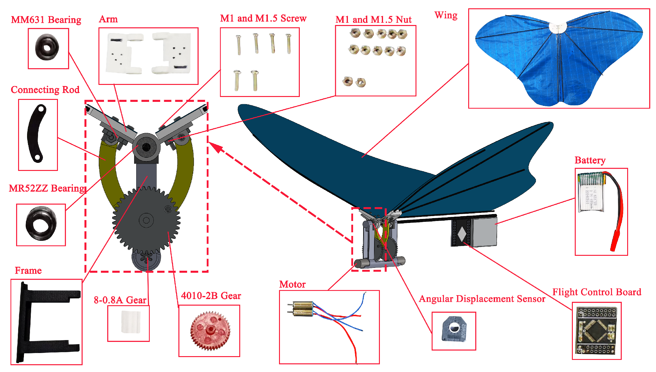
The crank rocker and frame models, designed using SolidWorks 2022 software, were fabricated with a CREALITY 3D printer. Ball bearings were installed at the joints to maximize weight reduction while maintaining sufficient strength, reduce wear, and prolong service life. The components of the biomimetic butterfly are shown in Figure 24.
The fuselage of the biomimetic butterfly aircraft is constructed using 3 mm carbon fiber rods. The motor mount and gear assembly are fixed at one end of the carbon fiber rods forming the fuselage. The control board with a built-in receiver and the lithium battery are secured to the carbon fiber rods using cable ties. By adjusting the positions of the lithium battery and control board, the center of gravity of the aircraft can be fine-tuned. The assembled biomimetic butterfly prototype is shown in Figure 25.
The total weight of the fabricated prototype was measured as 20.6 g using an electronic balance, which is consistent with the estimated mass. Based on the calculations in Section 4.4, the generated lift is considered sufficient to meet the flight requirements.

6. System Simulation Analysis and Experimental Testing

6.1. Stability Simulation Analysis

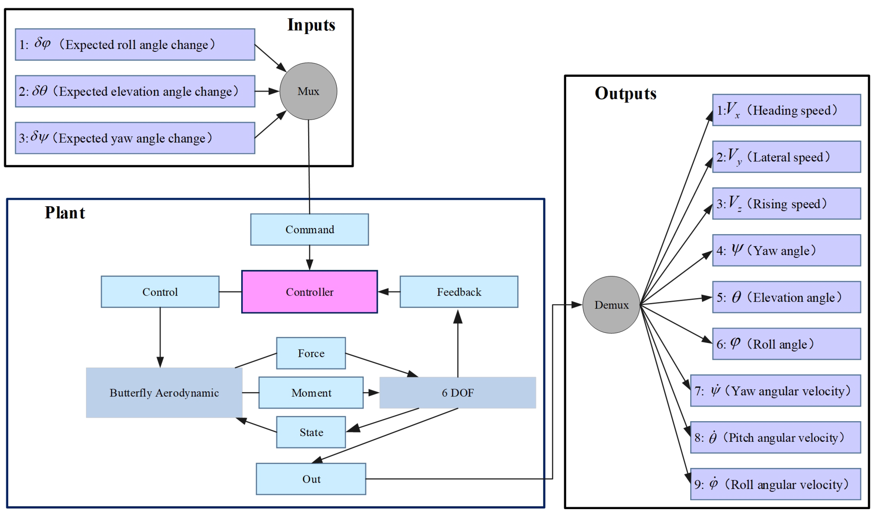
Following the method of establishing a stability analysis simulation model for the aircraft [59], the stability of the designed biomimetic butterfly aircraft was analyzed using the Simulink toolbox in MATLAB. Based on the kinematic model established in Section 4.1, the aerodynamic model constructed in Section 4.2, and a PID controller, the stability analysis model shown in Figure 26 was developed.
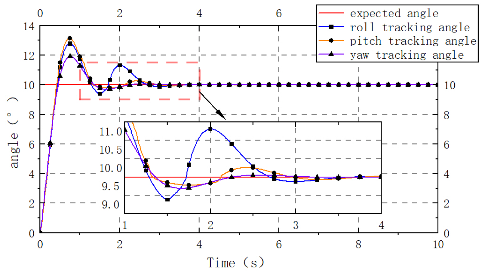
The analysis includes controlling the aircraft’s pitch, roll, and yaw angles. A step input of 10° is individually applied to the system for the desired pitch moment δ M y , roll moment δ M x , and yaw moment δ M z . PID parameters are adjusted to achieve satisfactory tracking performance. Subsequently, the time responses of the pitch angle θ , roll angle ϕ , and yaw angle ψ are observed, and their dynamic characteristics are analyzed. The simulation results are shown in Figure 27.
When the system is given a desired input of 10° for roll, pitch, and yaw angles respectively, the roll response initially exhibits an overshoot of approximately 2.7° but quickly stabilizes and approaches the desired roll angle after a brief adjustment period. The pitch response shows an initial overshoot of about 3.1°, then rapidly stabilizes near the desired pitch angle. The yaw response experiences an overshoot of roughly 2° but also converges quickly to the desired value. The response speeds for all three angles meet the requirements, with no high-frequency oscillations or divergence observed, and all ultimately reach stable values. Therefore, it can be concluded that the system’s stability meets the specified criteria.

6.2. Prototype Performance Testing

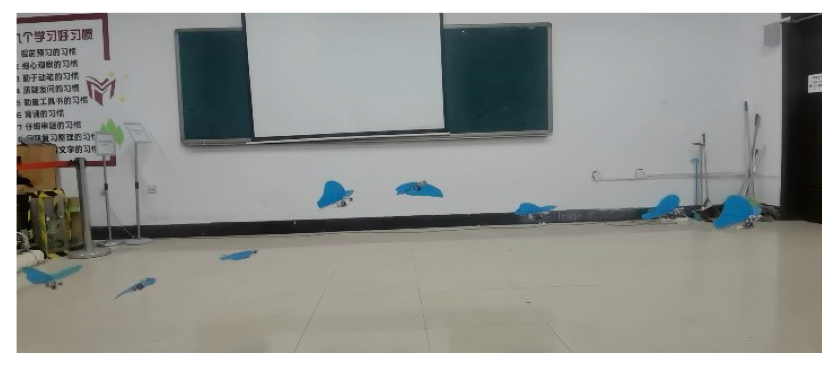
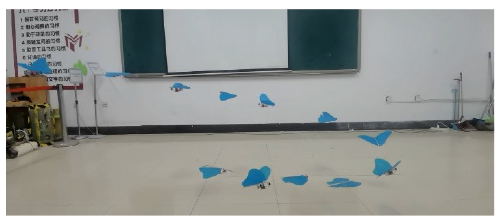
To eliminate the influence of wind speed on test flights, the flight tests were conducted indoors. The fabricated prototype is capable of both level flight and directional flight, as shown in Figure 28 and Figure 29.
The prototype is capable of continuous flight and was tested under the calculated operating conditions. The flight duration is approximately 2 min, with a speed of about 0.6 m/s, an altitude around 1.5 m, and a pitch angle near 60°, which closely aligns with simulation results. It can be concluded that the flight performance of the biomimetic butterfly aircraft essentially meets the design requirements.
Following the evaluation criteria in references [60,61], the flight performance of the prototype was tested, focusing on level flight performance, climb performance, and endurance. Based on the level flight performance curve shown in Figure 30a, the climb performance curve in Figure 30b was obtained. Using MATLAB, the power characteristic curve of the designed biomimetic butterfly was fitted as shown in Figure 30c. A tangent parallel to the x-axis yields the endurance speed V L . max = 0.293 m/s, while a tangent passing through the origin gives the range speed V R . max = 0.736 m/s.
Testing results indicate that the biomimetic butterfly flapping-wing aircraft can fly for approximately 3 min at the endurance speed and for about 1 min at the range speed.

6.3. Prototype Performance Evaluation

The geometric parameters and flight performance of the high-performance biomimetic butterfly were compared with those of USTbutterfly1 and USTbutterfly2 designed by Huang Haifeng, as well as the biomimetic butterfly driven by dual servos designed and fabricated by Leng Ye. The comparison is presented in Table 6.
In terms of geometric parameters, the designed aircraft features a smaller wingspan and lower mass compared to the three biomimetic butterflies, offering improved concealment and maneuverability. Regarding flight performance, the high-performance biomimetic butterfly surpasses the dual-servo-driven biomimetic butterfly, which is limited to gliding, across all three evaluated parameters. Compared to USTbutterfly1 and USTbutterfly2, it exhibits superior climb performance, while the other two parameters still show some gaps.

7. Results

  • The designed prototype has a wing-flapping amplitude of 93.34°, with an upper stroke limit angle of 62.07° during the upward flap and a lower stroke limit angle of −31.27° during the downward flap. This flapping range closely matches the wing-flapping amplitude observed in natural butterfly flight.
  • The designed flapping-wing drive mechanism operates smoothly and features a rational structure. Prototype flight tests have verified its capability to achieve continuous-level flight and turning maneuvers, fulfilling basic flight functions.
  • The adopted inline asymmetric flapping-wing drive device significantly reduces the aircraft’s mass and shortens the wingspan, resulting in a biomimetic butterfly aircraft with much lower mass and volume compared to existing similar biomimetic flyers, while demonstrating excellent agility and maneuverability in flight performance.
This research provides new insights for the design of biomimetic aircraft and offers a valuable reference for the future development of lightweight and high-efficiency flying vehicles.

8. Discussion

This study successfully designed and fabricated a high-performance biomimetic butterfly flyer with a mass of only 20.6 g and a wingspan of 0.295 m, achieving the core objectives of miniaturization and lightweight design. The flight test results—maximum speed of 0.9 m/s, climb rate of 0.12 m/s, and endurance up to 3 min—strongly validate the effectiveness and advancement of our design scheme. These outcomes not only demonstrate the attainment of technical parameters, but, more importantly, showcase the feasibility of achieving stable and efficient flight under stringent size and weight constraints.
Compared with previous studies, the prominent advantage of this design lies in its extremely low mass and compact wingspan. Although many existing flapping-wing aircraft may excel in certain individual performance metrics (such as flight speed or endurance), they often do so at the expense of larger size and weight. This study, through in-depth analysis of butterfly flight mechanics and the adoption of an innovative drive mechanism design, significantly optimizes the aircraft’s size and power-to-weight ratio while ensuring good flight performance. This characteristic endows the flyer with unique potential in applications requiring high concealment and maneuverability, such as indoor reconnaissance or exploration in confined spaces. Our findings align with prior research aimed at enhancing the maneuverability and biomimetic fidelity of flapping-wing aircraft, and by successfully realizing a physical prototype, we bridge theory and simulation with practical validation.
Another important contribution of this study is the adoption of a comprehensive and rigorous design and verification process. We first performed sensitivity analysis and optimization of the drive mechanism using MATLAB, and subsequently established a dynamic model for theoretical calculations, employing professional software such as XFLOW and SIMULINK for aerodynamic and flight stability simulations. This integrated approach—combining theoretical analysis, multi-software collaborative simulation, and final physical prototype testing—not only ensures the reliability of the design but also provides a systematic and referable design paradigm for future similar aircraft development. It demonstrates that conducting comprehensive simulation verification prior to prototype fabrication is a key step to improving R & D efficiency and success rate.
Although this research has achieved certain valuable phased results, there are still several deficiencies that need to be improved urgently, such as motor overheating, fatigue damage to the motion mechanism, short battery life (about 3 min), and the lack of integrated intelligent payloads. In response to the above challenges, subsequent research plans to systematically advance and solve them by considering aspects such as the development and application of new materials for core components, the research and development of high-energy-density micro-battery technology, and the integration and fusion of multiple sensors. In addition, current flight control relies on manual remote control. In the future, it could gradually transition to autonomous flight mode, with a focus on developing autonomous navigation and obstacle avoidance algorithms based on on-board sensors to enhance the intelligence level of aircraft. At the same time, it is also necessary to systematically study the flight stability and anti-interference ability of the aircraft in complex outdoor wind field environments.
In summary, this study not only successfully developed a high-performance miniature biomimetic butterfly flyer but, more importantly, validated an effective design philosophy and technical approach, opening new avenues for the development of small, lightweight flapping-wing aircraft. This work lays a solid foundation for the emergence of higher-performance, more intelligent micro-biomimetic flyers in the future and heralds their broad application prospects in military reconnaissance, environmental monitoring, and even scientific exploration.

Author Contributions

Conceptualization, D.Z.; methodology, Z.L. and G.Q.; software, G.Q.; validation, Z.L.; formal analysis, Z.L. and G.Q.; investigation, Z.L.; resources, H.L.; data curation, Z.L. and G.Q.; writing-original draft preparation, Z.L.; writing-review and editing, D.Z.; visualization, Z.L. and G.Q.; supervision, H.L. and D.Z.; project administration, H.L.; funding acquisition, H.L. All authors have read and agreed to the published version of the manuscript.

Funding

This research was funded by Open Fund of Liaoning Provincial Key Laboratory OF Liaoning Provincial Natural Science Foundation (Key R&D Program Guidance Plan) grant number 2023010235 and Modeling, Experimentation, and Analysis of a Whole-Satellite Nonlinear Travel-Amplified Energy Harvesting and Vibration Reduction System of the National Natural Science Foundation of China grant number 11902203.

Conflicts of Interest

The authors declare no conflicts of interest.

Abbreviations

The following abbreviations are used in this manuscript:
OFATOne Factor at a Time
TSTournament Selection
SBXSimulated Binary Crossover
PMPolynomial Mutation
CDPConstraint Dominance Principle

References

  1. Meng, X. Development status and trend of micro Aerial Vehicle. In Proceedings of the 6th China International Unmanned Aerial Vehicle Systems Conference, Beijing, China, 19–23 September 2016. [Google Scholar]
  2. Han, J.; Hui, Z.; Tian, F.; Chen, G. Review on bio-inspired flight systems and bionic aerodynamics. Chin. J. Aeronaut. 2021, 34, 170–186. [Google Scholar] [CrossRef]
  3. Xiao, Y.; Cui, F.; Zhang, Y.; Zhao, J.; Wu, C.; Xiao, Y. Butterfly Inspired Flapping Wing Air Vehicles: Research Progress, Challenges and Future Developments. Unmanned Syst. Technol. 2023, 6, 45–58. [Google Scholar]
  4. Chang, E.; Chin, D.; Lentink, D. Bird-Inspired Reflexive Morphing Enables Rudderless Flight. Sci. Robot. 2024, 9, eado4535. [Google Scholar] [CrossRef] [PubMed]
  5. Lee, S.G.; Yang, H.H.; Lee, E.H.; Han, J.H. Gravity-Assisted Takeoff of Bird-Inspired Flapping-Wing Air Vehicle Using Cliff-Drop. J. Bionic Eng. 2025, 22, 144–156. [Google Scholar]
  6. Hammad, A.; Armanini, S. Landing and Take-Off Capabilities of Bioinspired Aerial Vehicles: A Review. Bioinspiration Biomimetics 2024, 19, 031001. [Google Scholar] [CrossRef]
  7. Park, J.H.; Yoon, K.-J. Designing a Biomimetic Ornithopter Capable of Sustained and Controlled Flight. J. Bionic Eng. 2008, 5, 39–47. [Google Scholar] [CrossRef]
  8. Chu, Z. Development and Dynamic Analysis of a Bionic Flapping Wing Micro Air Vehicle. Master’s Thesis, Jilin University, Changchun, China, 2021. [Google Scholar]
  9. Wang, L.; Song, B.; Sun, Z.; Yang, X. Review on ultra-lightweight flapping-wing nano air vehicles: Artificial muscles, flight control mechanism, and biomimetic wings. Chin. J. Aeronaut. 2023, 36, 63–91. [Google Scholar] [CrossRef]
  10. He, W.; Mu, X.; Zhang, L.; Zou, Y. Modeling and trajectory tracking control for flapping-wing micro aerial vehicles. IEEE/CAA J. Autom. Sin. 2021, 8, 148–156. [Google Scholar] [CrossRef]
  11. Han, J.-H.; Han, Y.-J.; Yang, H.-H.; Lee, S.-G.; Lee, E.-H. A Review of Flapping Mechanisms for Avian-Inspired Flapping-Wing Air Vehicles. Aerospace 2023, 10, 554. [Google Scholar] [CrossRef]
  12. Shi, Y.; He, W.; Guo, M.; Xia, D.; Luo, X.; Ji, X. Mechanism Design and Motion Analysis of a Flapping-Wing Air Vehicle. Math. Probl. Eng. 2022, 2022, 1–11. [Google Scholar] [CrossRef]
  13. Wang, P.; Wang, H.; Gu, G. Structure Design and Simulation of Single-crank and Double-rocker Mechanism with Phase-Free Flapping Wing Drive. Mach. Manuf. Autom. 2020, 49, 94–96+126. [Google Scholar]
  14. Huang, H. Control System Design and Research of Servo-Driven Bionic Flapping-Wing Aerial Robots. Ph.D. Thesis, University of Science and Technology Beijing, Beijing, China, 2023. [Google Scholar]
  15. Huang, H.; He, W.; Chen, Z.; Niu, T.; Fu, Q. Development and Experimental Characterization of a Robotic Butterfly with a Mass Shifter Mechanism. Biomim. Intell. Robot. 2022, 2, 4. [Google Scholar] [CrossRef]
  16. Ando, N.; Hirai, N.; Lima, M.; Senda, K. Electromyography of Flight Muscles in Free-Flying Chestnut Tiger Butterfly, Parantica sita. Zool. Sci. 2024, 41, 557–563. [Google Scholar] [CrossRef]
  17. Muniappan, A.; Baskar, V.; Duriyananhan, V. Lift and Thrust Characteristics of Flapping Wing Micro Air Vehicle (MAV). In Proceedings of the 43rd AIAA Aerospace Sciences Meeting and Exhibit, Reno, NV, USA, 10–13 January 2005. [Google Scholar] [CrossRef]
  18. Bode-Oke, A.T.; Dong, H. The Reverse Flight of a Monarch Butterfly (Danaus plexippus) Is Characterized by a Weight-Supporting Upstroke and Postural Changes. J. R. Soc. Interface 2020, 17, 20200268. [Google Scholar] [CrossRef]
  19. Li, C. Research on Conceptual Design and Performance Analysis of 15 cm Fixed-Wing MAV. Master’s Thesis, Nanjing University of Aeronautics and Astronautics, Nanjing, China, 2007. [Google Scholar]
  20. Ding, M.; Zhao, Q.; Ma, S.; Liu, Z.; Zhang, M.; He, G. Progress in the Study of Micro Aerial Vehicle (MAV) and the Key Technologies. J. Weapon Equip. Eng. 2023, 44, 1–11. [Google Scholar]
  21. Leng, Y. Design and Manufacture of a Butterfly-Like Aircraft. Master’s Thesis, Shanghai Jiao Tong University, Shanghai, China, 2019. [Google Scholar]
  22. Leng, Y.; Zhang, W.; Zhou, S.; Chen, X.; Ge, W. Design and Research of Bionic Butterfly Aircraft. Mech. Des. Res. 2019, 35, 32–35+42. [Google Scholar]
  23. Huang, H.; He, W.; Zou, Y.; Fu, Q. USTButterfly: A Servo-Driven Biomimetic Robotic Butterfly. IEEE Trans. Ind. Electron. 2024, 71, 1758–1767. [Google Scholar] [CrossRef]
  24. Chi, P.; Zhang, W.; Chen, W.; Li, H.; Meng, K.; Cui, F.; Liu, W.; Wu, X. Design and Fabrication of an SU-8 Biomimetic Flapping-wing Micro Air Vehicle by MEMS Technology. Robot 2011, 33, 366–370. [Google Scholar] [CrossRef]
  25. Cheng, H. Overall Design and Control Simulation of a Butterfly-Shaped Aircraft. Master’s Thesis, Nanjing University of Aeronautics and Astronautics, Nanjing, China, 2020. [Google Scholar]
  26. Chen, X. Design and Tracking Control of a Bionic Flapping-wing Micro Aerial Vehicle. Master’s Thesis, Hangzhou Dianzi University, Hangzhou, China, 2023. [Google Scholar]
  27. Zhang, Y.; Wang, X.; Zhang, G.; Yang, J. Design and Analysis of Single-Degree-of-Freedom Flapping Wing Mechanism Based on UG. J. Phys. Conf. Ser. 2020, 1629, 1. [Google Scholar] [CrossRef]
  28. Ma, D.; Song, B.; Cao, J.; Wang, J.; Xuan, J.; Xia, L. Investigating the Design Characteristics and Parameter Laws of Bird-Like Flapping-Wing Aerial Vehicles from the Perspective of Scaling. Bioinspiration Biomimetics 2025, 20, 02600. [Google Scholar] [CrossRef] [PubMed]
  29. Zhang, R.; He, W. Design and Dynamics Analysis of Space RSSR Flapping Wing Drive Mechanism. Hydraul. Pneum. 2023, 47, 176–183. [Google Scholar]
  30. Zhang, R.; He, W.; Wang, X.; Zheng, J.; Sun, L. Optimal Design of RSSR Quick-return Bionic Flapping-wing Mechanism in Offset Space. J. Mech. Sci. Technol. 2022, 41, 651–656. [Google Scholar]
  31. Jiang, J.; Zheng, X.; Feng, Z.; Shen, H. Multi-objective Optimum Design for High-frequency Flapping-wing Micro Air Vehicle Aircraft in Aviation Engineering. Aviat. Eng. 2019, 10, 80–86. [Google Scholar]
  32. Le Roy, C.; Amadori, D.; Charberet, S.; Windt, J.; Muijres, F.T.; Llaurens, V.; Debat, V. Adaptive Evolution of Flight in Morpho Butterflies. Science 2021, 374, 1158–1162. [Google Scholar] [CrossRef]
  33. Zhu, W. Research on Kinematic Synthesis Method of Spatial Four Bar Function Generating Mechanism. Master’s Thesis, Fuzhou University, Fuzhou, China, 2017. [Google Scholar]
  34. Jiang, H. Aerodynamic Characteristics of Flexible Flapping-Wing Micro Aerial Vehicle. Master’s Thesis, Harbin Institute of Technology, Harbin, China, 2016. [Google Scholar]
  35. Sahin, D.E. Dynamic Design of Crank-Rocker SI Engine Mechanism. J. Vib. Eng. Technol. 2022, 10, 2853–2875. [Google Scholar] [CrossRef]
  36. Wei, L.; Shen, G.; Huang, S.; Peng, G. Bionic Design on the Fluid Mechanics Experimental Model of Butterfly Hovering Fly. J. Beijing Univ. Aeronaut. Astronaut. 2011, 37, 421–427. [Google Scholar]
  37. Valdez, M.F.; Balachandran, B.; Preidikman, S. Comparative Study on Analytical and Computational Aerodynamic Models for Flapping Wings MAVs. Aeronaut. J. 2020, 124, 1636–1665. [Google Scholar] [CrossRef]
  38. Hospodář, P.; Klesa, J.; Demovič, D.; Žižkovský, N. Aerodynamic and Structural Aspects of a Distributed Propulsion System for Commuter Airplane. Aerospace 2022, 9, 712. [Google Scholar] [CrossRef]
  39. Wang, C.; Zhang, W.; Hu, J.; Zhao, J.; Zou, Y. A Modified Quasisteady Aerodynamic Model for a Sub-100 mg Insect-Inspired Flapping-Wing Robot. Appl. Bionics Biomech. 2020, 2020, 8850036. [Google Scholar] [CrossRef] [PubMed]
  40. Lee, N.; Lee, S.; Cho, H.; Shin, S.J. Effect of Flexibility on Flapping Wing Characteristics in Hover and Forward Flight. Comput. Fluids 2018, 173, 111–117. [Google Scholar] [CrossRef]
  41. Huang, Z. Research on Aerodynamics and Flight Efficiency of Flexible Wing Biomimetic Flapping Wing Aircraft. Master’s Thesis, Guangxi University, Nanning, China, 2024. [Google Scholar]
  42. Zhang, Y.; Wang, X.; Wang, S.; Huang, W.; Weng, Q. Kinematic and Aerodynamic Investigation of the Butterfly in Forward Free Flight for the Butterfly-Inspired Flapping Wing Air Vehicle. Appl. Sci. 2021, 11, 2620. [Google Scholar] [CrossRef]
  43. Ortega Ancel, A.; Eastwood, R.; Vogt, D.; Ithier, C.; Smith, M.; Wood, R.; Kovač, M. Aerodynamic Evaluation of Wing Shape and Wing Orientation in Four Butterfly Species Using Numerical Simulations and a Low-Speed Wind Tunnel, and Its Implications for the Design of Flying Micro-Robots. Interface Focus 2017, 7, 20160087. [Google Scholar] [CrossRef]
  44. Sun, M.; Tang, J. Biomimetic Fluid Mechanics of Micro Aerial Vehicles-Mechanism of Insects’ High Lift Generation and Required Power. In Proceedings of the 7th National Symposium on Air Elasticity, Huzhou, China, 1 October 2001. [Google Scholar]
  45. Dudley, R. Biomechanics of Flight in Neotropical Butterflies: Morphometries and Kinematics. J. Exp. Biol. 1990, 150, 37–53. [Google Scholar] [CrossRef]
  46. Deng, X.; Schenato, L.; Sastry, S. Model Identification and Attitude Control Scheme for a Micromechanical Flying Insect. In Proceedings of the 7th International Conference on Control, Automation, Robotics and Vision, Singapore, 2–5 December 2002. [Google Scholar]
  47. Deng, X.; Schenato, L.; Sastry, S. Model Identification and Attitude Control for a Micromechanical Flying Insect Including Thorax and Sensor Models. In Proceedings of the 2003 IEEE International Conference on Robotics and Automation, Taipei, Taiwan, 14–19 September 2003. [Google Scholar]
  48. Dickinson, M.H.; Lehmann, F.-O.; Sane, S.P. Wing Rotation and the Aerodynamic Basis of Insect Flight. Science 1999, 284, 1954–1960. [Google Scholar] [CrossRef] [PubMed]
  49. Jiang, J.; Zhang, Z.; Lu, Y.; Zhang, T.; Zhang, J.; Li, J.; Miu, F.; Wang, Y.; Wu, K.; Zhang, D. Numerical Analysis of Wind Loads about Photovoltaic Arrays Considering Bending Moment. Renew. Energy 2019, 37, 46–52. [Google Scholar]
  50. NASA. The Menter Shear Stress Transport Turbulence Model. Available online: https://turbmodels.larc.nasa.gov/sst.html (accessed on 5 February 2025).
  51. Sun, M.; Huang, H. Biominetic Mechanics of Micro-Air Vehicles: The Aerodynamic Force of Butterfly in Forward Flight. J. Beijing Univ. Aeronaut. Astronaut. 2006, 10, 1146–1151. [Google Scholar]
  52. Sun, M.; Tang, J. Biomimetic Fluid Mechanics of Micro Aerial Vehicles-Mechanism of Insects’ High Lift Generation. In Proceedings of the New Century Mechanics Workshop—Review and Prospects of Qian Xuesen’s Technological Scientific Thought, Beijing, China, 19–20 November 2001. [Google Scholar]
  53. Johansson, L.C.; Henningsson, P. Butterflies Fly Using Efficient Propulsive Clap Mechanism Owing to Flexible Wings. J. R. Soc. Interface 2021, 18, 174. [Google Scholar] [CrossRef]
  54. Lang, X.; Song, B.; Yang, W.; Yang, X.; Xue, D. Sensitivity Analysis of Wing Geometric and Kinematic Parameters for the Aerodynamic Performance of Hovering Flapping Wing. Aerospace 2023, 10, 74. [Google Scholar] [CrossRef]
  55. Zhang, Y.; Wang, Z.; Zheng, H. Aerodynamic Analysis and Design Optimization of a Novel Flapping Wing Micro Air Vehicle in Hovering Flight. J. Appl. Fluid Mech. 2023, 16, 505–517. [Google Scholar] [CrossRef]
  56. Doman, D.; Oppenheimer, M.; Sigthorsson, D. Dynamics and Control of a Biomimetic Vehicle Using Biased Wingbeat Forcing Functions: Part II-Controller. In Proceedings of the 48th AIAA Aerospace Sciences Meeting Including the New Horizons Forum and Aerospace Exposition, Orlando, FL, USA, 4–7 January 2010; American Institute of Aeronautics and Astronautics: Reston, VA, USA, 2010. [Google Scholar]
  57. Ji, B.; Zhu, Z.; Guo, S.; Chen, S.; Zhu, Q.; Li, Y.; Yang, F.; Song, R.; Li, Y. Aerodynamic Analysis of a Flapping Wing Aircraft for Short Landing. Appl. Sci. 2020, 10, 3404. [Google Scholar] [CrossRef]
  58. Wen, B.; Zhang, Y.; Chen, L.; Sun, Z.; Chen, L.; Gong, Y. Mechanical Design Manual, 6th ed.; Volume 2: Mechanical Component Design, Connection, Tightening, and Transmission; Machinery Industry Press: Beijing, China, 2018. [Google Scholar]
  59. Zuo, D.; Chen, W.; Song, L.; Zhang, W. Modeling and Simulation Study of an Insect-Like Flapping-Wing Micro Aerial Vehicle. Adv. Robot. 2006, 20, 807–824. [Google Scholar] [CrossRef]
  60. Yang, W.; Song, B.; Gao, G. Flight Performance Estimation of Bionic Flapping-Wing Micro Air Vehicle. J. Northwestern Polytech. Univ. 2018, 36, 636–643. [Google Scholar] [CrossRef][Green Version]
  61. Fu, P.; Song, B.; Liang, S.; Yang, W. An Experimental Research about the Characteristics of Thrust and Power of FMAV. J. Northwestern Polytech. Univ. 2016, 34, 976–981. [Google Scholar][Green Version]
Figure 1. Distribution of muscles controlling butterfly’s wing movement.
Machines 13 00829 g001
Figure 2. Crank-rocker combined with reduction gear set center-symmetric drive mechanism.
Machines 13 00829 g002
Figure 3. Skeleton of the designed mechanism.
Machines 13 00829 g003
Figure 4. Morpho peleides.
Machines 13 00829 g004
Figure 5. Comparison of wing dimensions.
Machines 13 00829 g005
Figure 6. Wing structure.
Machines 13 00829 g006
Figure 7. Comparison of design processes. (a) Sample design flow. (b) Conventional design flow.
Machines 13 00829 g007
Figure 8. Control system composition.
Machines 13 00829 g008
Figure 9. Coordinate system of the right wing drive and definition of each rod length.
Machines 13 00829 g009
Figure 10. Sensitivity analysis of key parameters of the flapping-wing drive mechanism with respect to rod lengths: (a) Sensitivity analysis of the motion range of the E C 2 rod with respect to the length of the O 2 A 2 rod. (b) Sensitivity analysis of the motion range of the E C 2 rod with respect to the length of the A 2 B 2 rod. (c) Sensitivity analysis of the motion range of the E C 2 rod with respect to the length of the B 2 E rod. (d) Sensitivity analysis of the motion range of the E C 2 rod with respect to the length of the E C 2 rod. (e) Sensitivity analysis of the motion range of the E C 2 rod with respect to the length of the C 2 O 2 rod. (f) Sensitivity analysis of the motion smoothness of the E C 2 rod with respect to various rod lengths.
Machines 13 00829 g010
Figure 11. Sensitivity analysis of mass with respect to rod length.
Machines 13 00829 g011
Figure 12. Angular displacement analysis diagram of the crank–rocker mechanism.
Machines 13 00829 g012
Figure 13. Definitions of various quantities in the kinematic analysis of the crank–rocker mechanism.
Machines 13 00829 g013
Figure 14. Angular velocity of the rocker C 2 E B 2 as a function of time.
Machines 13 00829 g014
Figure 15. Angular acceleration of the crank C 2 E B 2 as a function of time.
Machines 13 00829 g015
Figure 16. Ground coordinate system and body coordinate system.
Machines 13 00829 g016
Figure 17. Wing coordinate system.
Machines 13 00829 g017
Figure 18. Biomimetic butterfly aerodynamic computational model.
Machines 13 00829 g018
Figure 19. Overall flow domain.
Machines 13 00829 g019
Figure 20. Comparison chart of periodic lift.
Machines 13 00829 g020
Figure 21. Comparison chart of periodic thrust.
Machines 13 00829 g021
Figure 22. Sensitivity analysis of lift with respect to kinematic parameters.
Machines 13 00829 g022
Figure 23. Torque at the crankshaft center.
Machines 13 00829 g023
Figure 24. Prototype components.
Machines 13 00829 g024
Figure 25. Biomimetic butterfly aircraft prototype. (a) Front (b) Back.
Machines 13 00829 g025
Figure 26. Stability analysis simulation model.
Machines 13 00829 g026
Figure 27. Step response of roll, pitch, and yaw angles.
Machines 13 00829 g027
Figure 28. Level flight.
Machines 13 00829 g028
Figure 29. Turning.
Figure 29. Turning.
Machines 13 00829 g029
Figure 30. Flight performance test results: (a) Level flight performance curve. (b) Climb rate curve of the aircraft. (c) Power characteristic curve of the aircraft.
Machines 13 00829 g030
Table 1. Nominal parameters used in the sensitivity analysis.
Parametersl1l2l3l4l5
Length (mm)51821016
Table 2. The functional relationship between mass and rod length.
RodFitting Results
O 2 A 2 y 1 = 0.4
A 2 B 2 y 2 = l 2 · 9.9554 × 10 4 + 0.10439
B 2 E y 3 = l 3 · 9.053 × 10 5 + 0.01882
E C 2 y 4 = l 4 · 1.17 × 10 3 + 0.19653
C 2 O 2 y 5 = l 5 · 2.64 × 10 3 + 0.72065
Table 3. Parameter summary.
ParameterValue/Type
Population Size150
Maximum Number of Iterations300
Selection OperatorTS (Tournament Selection)
Crossover OperatorSBX (Simulated Binary Crossover)
Crossover Probability0.9
Mutation OperatorPM (Polynomial Mutation)
Mutation Rate0.2
Constraint HandlingCDP (Constraint Dominance Principle)
Table 4. Optimization results.
ParameterLength (mm)Length ChangeMass Change
l 1 6+20%−0.52%
l 2 16.5−8.3%
l 3 2.2+10%
l 4 8.7−13%
l 5 15−6.7%
Table 5. Flow field mesh parameters.
Flow Field TypeFlow Field Range (m3)Mesh Density (m3)Number of Meshes
Virtual wind tunnel 3.5 × 3.5 × 3.5 ( 0.001 ) 3 3,624,743
Table 6. Comparison of parameters of biomimetic butterfly prototypes.
ParameterHigh PerformanceUST1UST2Dual Servo
Wingspan (m)0.2950.90.50.498
Mass (g)20.6725432.2
Max Speed (m/s)0.971.541.771.2 (Glide)
Climb Rate (m/s)0.120.0970.10−0.5
Endurance (min)3>5>5<1
Disclaimer/Publisher’s Note: The statements, opinions and data contained in all publications are solely those of the individual author(s) and contributor(s) and not of MDPI and/or the editor(s). MDPI and/or the editor(s) disclaim responsibility for any injury to people or property resulting from any ideas, methods, instructions or products referred to in the content.