Abstract
Wind turbine blades feature complex geometries and operate under harsh conditions, including high curvature gradients, nonlinear deformations, elevated humidity, and particulate contamination. This study presents the design and kinematic analysis of a novel climbing robot based on a 10R folding metamorphic mechanism. The robot employs a hybrid wheel-leg drive and adaptively reconfigures between rectangular and hexagonal topologies to ensure precise adhesion and efficient locomotion along blade leading edges and windward surfaces. A high-order kinematic model, derived from a modified Grubler–Kutzbach criterion augmented by rotor theory, captures the mechanism’s intricate motion characteristics. We analyze the degrees of freedom (DOF) and motion branch transitions for three representative singular configurations, elucidating their evolution and constraint conditions. A scaled-down prototype, integrating servo actuators, vacuum adhesion, and multi-modal sensing on an MDOF control platform, was fabricated and tested. Experimental results demonstrate a configuration switching time of 6.3 s, a single joint response time of 0.4 s, and a maximum crawling speed of 125 mm/s, thereby validating stable adhesion and surface tracking performance. This work provides both theoretical insights and practical validation for the intelligent maintenance of wind turbine blades.
1. Introduction
Currently, with the continuous growth of wind power installation capacity, the tasks of regular cleaning, inspection, and maintenance of wind turbine blades are becoming increasingly demanding. Blades often exceed 80 m in length, with large-scale non-uniform curvature variations on their surfaces, and they operate in complex environments characterized by high altitude, high humidity, and high dust levels. Traditional manual operations not only involve high risks and low efficiency but are also severely limited by these harsh conditions. Therefore, there is an urgent need for intelligent equipment with excellent environmental adaptability and structural flexibility to replace human labor. As a viable alternative, wall-climbing robots can carry various operation and maintenance inspection devices to perform automated tasks on high-altitude vertical surfaces, showing broad application prospects in industries such as petrochemicals, shipping, wind power, and national defense [1,2,3,4,5,6,7,8,9,10,11,12,13].
In the research on wall-climbing robots, adhesion technologies, mobility mechanisms, and drive systems are three key areas. Current mainstream adhesion methods include magnetic adhesion [3,4,6], vacuum adhesion [10,11], and propeller-based thrust adhesion. Given that wind turbine blades are mostly made of composite materials such as glass fiber reinforced resin and carbon fiber, their non-magnetic properties rule out the application of magnetic adhesion. Meanwhile, high-altitude strong wind conditions can easily disrupt the stability of propeller-based adhesion, posing reliability risks. In contrast, vacuum adhesion offers a compact and lightweight structure, better adaptability to curved surfaces, and effective overall weight control while maintaining adhesion performance, making it a more suitable adhesion solution for climbing robots.
In terms of mobility mechanisms, common types include legged [3,4], tracked [2,5], wheeled [3,4,5], and cable-climbing systems. Wheeled mechanisms offer high mobility efficiency but poor surface adaptability; tracked systems provide strong load capacity but are structurally redundant and heavy; legged designs demonstrate excellent terrain adaptability, while cable-climbing systems combine high-speed movement with strong safety performance. To balance curvature adaptability, structural compactness, and load capacity, this paper proposes a hybrid mobility solution that integrates a wheel-legged mechanism with cable-climbing technology.
Drive systems mainly include hydraulic drives, pneumatic drives [12], and electric drives [3,4,5,6,7]. Hydraulic drives offer advantages such as high power density, fast response, and stepless speed regulation, along with self-lubrication properties, but they suffer from low energy efficiency, strict requirements for medium purity, and complex system maintenance. Pneumatic drives are cost-effective, environmentally friendly, and responsive, making them particularly suitable for long-distance air supply and linear motion, though they are prone to noise and leakage issues. Electric drives provide precise control, high efficiency, and flexible layout, making them more suitable for high-precision operation scenarios. Considering the specific working conditions of wind turbine blade climbing robots, this study ultimately selects an electric drive system.
In the field of wind turbine blade inspection robots, numerous scholars have conducted relevant research. Liu and Padrigalan et al. [8,9,10] systematically explored wall-climbing robots for wind turbine towers and blades, covering technologies such as Mecanum wheel spiral climbing, vacuum adhesion tracks, and cable and multi-wheel composite structures, preliminarily establishing a comprehensive robotic technology framework. Gao et al. [11] proposed a mechanical design for a wheel-legged quadruped suction cup wall-climbing robot, achieving obstacle traversal on single curved surfaces and inner right-angle crossing. Zhang et al. [12] designed a wind turbine blade inspection robot based on legged mobility and composite adhesion.
However, most existing robots are limited by rigid structures, making it difficult to adapt to the large curvature gradients on wind turbine blade surfaces or operate in narrow leading-edge areas, while also exhibiting poor stability when crossing high-risk regions such as blade edges. Metamorphic mechanisms, with their variable topology and multi-configuration capabilities, offer a new solution to these challenges. This concept was first proposed by Dai et al. in 1998 [14], referring to mechanisms capable of smoothly transitioning between different configurations by changing the number of components, states, and degrees of freedom while maintaining continuous motion. They exhibit strong adaptability for “one machine, multiple uses” and have been widely applied in complex terrain search and rescue, unknown environment exploration, and field inspection [15,16,17,18,19,20,21,22,23,24,25]. For example, Tang et al. [26] developed the Origaker quadruped robot, capable of adaptive multi-mode switching; Wang et al. [27] and Pan et al. [28] developed passive metamorphic structures and spatial eight-bar mechanisms for pipeline and complex terrain traversal; Guan et al. [29] designed a shape-shifting flipping robot capable of mimicking multiple biological motion modes; Han et al. [30] and Zhao et al. [31] proposed wheel-legged composite and multi-mode mobility platforms, demonstrating excellent environmental traversal and morphological transformation capabilities.
To address the challenges of high altitude, high risk, and high cost in the maintenance of large wind turbine blades, this paper integrates vacuum adhesion, electric drive, cable-climbing technology, and a wheel-legged composite mobility mechanism to design a climbing robot based on a 10R-Folding metamorphic mechanism. The main research contents include:
- (1)
- Proposing an overall structural design for a wind turbine blade wall-climbing robot based on a metamorphic mechanism, combining wheel-legged composite and cable-climbing mobility methods, and incorporating a 10R-Folding metamorphic trunk to significantly enhance the robot’s mobility flexibility and environmental adaptability;
- (2)
- Conducting systematic kinematic analysis, establishing closed-loop equations for the 10R-Folding trunk, performing higher-order kinematic modeling, and analyzing motion branches and configuration switching paths under singular configurations;
- (3)
- Developing a robot prototype and conducting configuration switching experiments, designing a supporting control system to achieve stable multi-configuration switching and motion verification.
The innovations of this paper lie in: organically integrating metamorphic mechanisms with the adhesion, mobility, and drive technologies of wall-climbing robots to achieve all-terrain adaptive climbing capabilities on complex curved surfaces of wind turbine blades; constructing a degree-of-freedom calculation model based on the modified Grubler–Kutzbach criterion, completing higher-order kinematic analysis using screw theory, and systematically revealing the degree-of-freedom evolution and motion branch transition mechanisms in three typical singular configurations.
2. Materials and Methods
2.1. Structural Design
2.1.1. Design Requirements
The wind turbine blade’s surface possesses non-uniform curvature, characterized by pronounced curvature at the leading and trailing edges in contrast to gentler curvature on the suction and pressure sides. Its chord length varies nonlinearly along the span. To accommodate these variations, a controllable adhesion system with dynamic pressure compensation and built-in failure warning was implemented, ensuring reliable operation in wet, slippery, and dust-laden environments. The robot achieves multi-directional adaptive pose control, with traversal speeds up to 300 mm/s and precise positioning at 150 mm/s. Its footprint (1000 mm × 800 mm) and low center of gravity result in a lightweight, compact form factor, constructed from high-strength, toughened materials for enhanced durability.
2.1.2. Constructive Design
Based on the complex curvature of wind turbine blades, we developed a 3D model of our wheel–leg hybrid climbing robot (see Figure 1). The system comprises a variable-cell 10R folding main body, load-bearing legs, clamping legs, a rope-based climbing module, a payload platform, a vacuum-adhesion system, an integrated control unit, and onboard inspection and maintenance instruments.
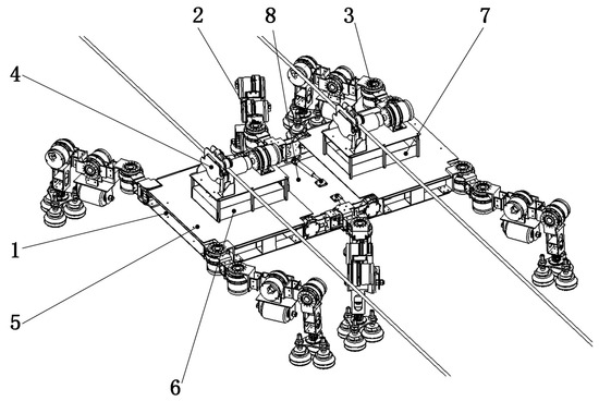
Figure 1.
Main components of the climbing robot: 1. 10R folding trunk, 2. Load-bearing legs, 3. Clamping legs, 4. Rope climbing device, 5. Load platform, 6. Vacuum generation system, 7. Control system, 8. Inspection and maintenance device.
2.1.3. Closed-Loop Folding of the Trunk 10R Folding
The overall structure of the climbing robot designed in this paper employs an electrically driven vacuum suction mechanism, integrated with a wheel-leg and rope-climbing mobility system. However, the torsos of traditional legged robots are typically rigid plates. While they can operate on both the windward and leeward sides of blades, their efficiency is low, their direct movement range is limited, and they cannot perform actions such as crossing over the leading and trailing edges of blades, making it difficult to achieve efficient all-terrain movement on blades. To enhance the robot’s stability and adaptability in complex environments, improve mobility efficiency, and enable traversal over leading and trailing edges, a 10R-Folding mechanism capable of folding and deformation was developed. This design evolved from research on variable-cell folding mechanisms and practical blade-climbing scenarios, as illustrated in Figure 2.
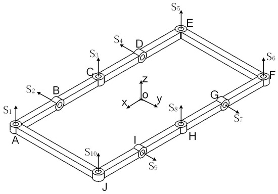
Figure 2.
Schematic Diagram of the 10R-Folding Variable Cell Mechanism.
To accurately determine the DOF of mechanisms featuring closed kinematic loops and redundant constraints, the traditional Grubler–Kutzbach criterion must be augmented with constraint-correction terms. By incorporating these corrective factors, the modified model more precisely captures the motion behavior of such specialized linkages. Its mathematical formulation is given in Equation (1).
In the formula, M is the degree of freedom of the entire mechanism;
d is the degree of freedom coefficient;
n is the number of links in the mechanism;
g is the number of kinematic pairs;
fi is the degree of freedom of the i-th kinematic pair;
v is the redundancy factor.
In its planar configuration, the 10R folding metamorphic mechanism comprises ten revolute joints, whose rotation-axis rotor is defined in Equation (2). Here, L1 denotes the lengths of links AJ and EF, while L2 denotes the lengths of links AB, DE, FG, IJ, BC, CD, GH, and HI. The mechanism’s topology consists of two kinematic branches forming a closed loop. Rotor-theory analysis shows that, in the examined configuration, the common-constraint rotor system has dimension 1 and the motion-rotor system has dimension 5. Substituting the freedom parameter d = 5 into the modified Grubler–Kutzbach criterion (Equation (1)) yields a total degree of freedom M = 5.
The torso of a climbing robot primarily houses various functional system components. By folding and unfolding the body structure in different operational modes, the robot’s flexibility is enhanced. When designing the torso structure of a climbing robot, it must meet requirements for compactness, rational layout, and ease of manufacturing. During the production process of components, manufacturing costs should be minimized as much as possible while ensuring sufficient strength and rigidity. The trunk structure (Figure 3) comprises key elements such as servo motors positioned at corner joints, swing-joint servomotors located at either end, passive revolute joints, motor-mount interfaces, and carbon-fiber connecting plates. Given the complex curved surface of wind turbine blades and the characteristics of the metamorphic mechanism, the robot’s joint control requires high precision and involves high torque loads. Therefore, a servo motor with a rated torque of 135 N·m was selected.
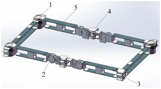
Figure 3.
10R folding trunk structure diagram. 1. Corner joint servo motor, 2. Swing joint servo motor, 3. Passive rotating joint, 4. Motor connection piece, 5. Carbon fiber connection plate.
The variable-cell closed-loop 10R-folding mechanism possesses five degrees of freedom and requires five rotational drives. Based on requirements, the torso can transform into a hexagonal structure, with both front and rear ends capable of vertical bending. Its motor-driven motion is illustrated in Figure 4.
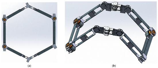
Figure 4.
Different working modes require different trunk shapes (a) The trunk is a hexagonal structure (b) The trunk is bent upward and downward at both ends.
The trunk integrates three drive motor assemblies at the vertices of its six vertical joints, while the four longitudinal bending joints subjected to higher loads each employ an independent drive motor. The remaining three joints use passive rotary bearings (see Figure 5). The symmetrical frame is fabricated from aluminum alloy and igus bearings: bearing housings are secured with four bolts, and flanges, shafts, and the main frame are all bolted together to maximize strength, reduce weight, and simplify manufacturing. Carbon fiber plates mount to the motor output shafts via dual-end motor brackets, and adjacent plates link through tie rod brackets and bolts to form a rigid support structure. This configuration yields a lightweight trunk capable of the required reconfiguration motions.
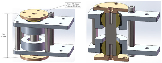
Figure 5.
Passive joint structure diagram.
2.1.4. Load Platform Design
In the closed-loop variable-cell 10R folding trunk, the constrained load capacity of individual links coupled with limited rod repositioning during deformation impede collaborative load distribution. To address this limitation, a load-bearing platform was designed that distributes forces across multiple links, thereby mitigating the impact of rod displacement. As shown in Figure 6, the payload platform comprises three modules—left, right, and central. The left and right modules transfer loads to the trunk’s end links via adjustable tie rods, while the central module connects to the upper and lower links through four tie rods, ensuring uniform load distribution and maintaining platform stability throughout trunk deformation.
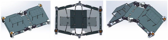
Figure 6.
Diagram showing the relationship between the position of the loading platform and changes in the trunk.
2.1.5. Clamping Leg and Load-Bearing Leg Design
Each leg of the climbing robot features a three DOF kinematic chain (see Figure 7), comprising a base segment, a thigh segment, and a shin segment. The base segment’s rotary joint motor provides fore–aft swinging, while the thigh and shin segment motors drive co-planar articulation. Of the six legs, four located at the upper corners serve as clamping legs, and the two mid-side legs function as primary load-bearing supports.
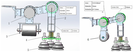
Figure 7.
Leg structure diagram. 1. Thigh section, 2. Shin section, 3. Clamping wheel, 4. Passive ball joint, 5. Vacuum suction cup, 6. Load-bearing wheel.
In the leading-edge mode, the base, femur, and tibia of the four clamping legs align linearly, positioning the clamp wheels to grip both sides of the blade’s leading edge for secure locomotion. The two load-bearing legs substitute their clamp wheels with conical support wheels, also arranging their joints in-line along the leading edge to enable rolling. To conform to surface irregularities while preserving vacuum suction, a spring-loaded passive ball joint replaces the distal femur rotary joint. This design prevents dead zones during bidirectional leg swing and provides sufficient stiffness to auto-level the footplate parallel to the tibia once the load is removed (see Figure 8).
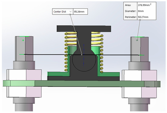
Figure 8.
Passive ball sub-structure diagram of the foot end.
2.1.6. Work Mode Analysis
When the turbine blade is oriented vertically downward, the robot can reconfigure its body into either a rectangular or a hexagonal posture to traverse the leading edge. In the rectangular configuration (see Figure 9a), two load-bearing legs and four clamping legs alternate their swings to produce highly efficient lateral motion while conforming to changes in blade curvature. For vertical ascent or descent, the load-bearing legs extend their thigh–shin axes parallel to the body, and the four clamping legs swing in sequence. By releasing the suction cups and employing the onboard climbing-rope mechanism, the robot can reposition across a large area before reattaching in its new posture. In contrast, the hexagonal configuration (see Figure 9b) provides enhanced omnidirectional mobility and agile turning, yielding a more stable support polygon for complex maneuvers along the blade’s leading edge.
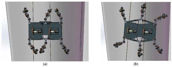
Figure 9.
Robot working on the windward side of the blade (a) Rectangular pattern for efficient movement (b) Hexagonal pattern for stable adhesion.
When operating on the blade’s leading edge, the robot first aligns itself while the blade is vertical, engaging its four clamping legs’ vacuum suction cups on either side of the edge. Simultaneously, the tibia–femur plates of the two load-bearing legs become collinear and parallel to the central load platform, allowing the load-bearing wheels to bear directly against the leading edge. As the blade rotates to a 45° incline with the leading edge facing upward, the clamping legs’ suction cups disengage and their wheels clamp firmly onto the edge. The robot then rapidly traverses up and down using its integrated climbing-rope mechanism. Once positioned at the worksite, the vacuum suction cups on all four clamping legs reattach, firmly securing the robot for inspection or maintenance tasks (see Figure 10).
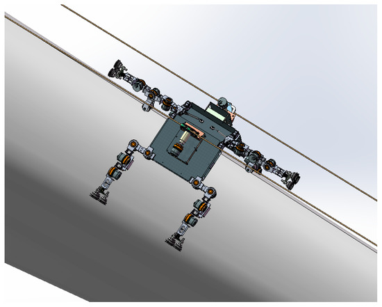
Figure 10.
Robot working mode at the leading edge of the blade.
2.1.7. Adsorption Analysis
The robot has six legs and primarily moves using a three-legged gait. In the extreme state of the three-legged gait, three legs are in the swinging phase and three legs are in the support phase. Only the suction cups at the ends of the three support legs adhere to the wind turbine blades. Therefore, a force analysis is conducted for this extreme state, with the force analysis diagram shown in Figure 11.
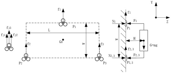
Figure 11.
Force analysis diagram of vacuum suction cup.
Through force analysis, the equilibrium equations for forces FY and FZ in the Y and Z directions can be obtained as follows:
Each leg of the robot has three double-layer suction cups connected to the same vacuum generator. The same model of vacuum generator is used on all three legs, meaning that the three vacuum suction cups have the same vacuum pressure. The suction force Fji of the double-layer suction cups is:
The safety factor for suction of the vacuum suction cup is η, which is 3 according to the empirical formula. The radius of the double-layer suction cup is represented by r, and the vacuum pressure is represented by p, with a value of p = 88 kPa. Therefore, the calculation of the force and torque in the X-axis direction at point P1 is shown in Equation (5):
The reaction forces exerted by the two sets of suction cups on the other side, i.e., the six double-layer suction cups at points P2 and P3, are equal in magnitude, i.e.,
To prevent the robot from tipping over due to instability, the reaction force of the suction cup at point P1, i.e., F1, must be greater than the supporting force N1. Therefore, the minimum radius rf of the suction cup to prevent the robot from tipping over can be calculated as:
In addition to avoiding instability and overturning due to unstable adhesion, robots may also slip due to insufficient adhesion, causing them to fall. Therefore, in order to prevent slippage, friction constraints must also be satisfied, namely:
Substituting Equations (3) and (6) into Equation (8), we obtain the minimum suction cup radius rs that satisfies the friction conditions and prevents the robot from falling due to slippage:
Therefore, to ensure that the robot does not tip over or slip, the minimum radius of the new disk is taken as the minimum value of the two conditions, i.e., the minimum radius rmin of the double-layer suction cup is:
After calculation, rf is found to be 29.2 mm and rs is 32.6 mm. Substituting these values into the equation yields rmin as 32.6 mm. Thus, the minimum diameter of the suction cup is 65.2 mm. The designed robot suction cup has a diameter of 80 mm, which meets the design requirements.
2.2. Kinematics Modeling
2.2.1. Basic Configuration and D-H Parameter Modeling
The Denavit–Hartenberg (D-H) convention was applied to derive the closed-loop kinematic equations of the 10R folding mechanism, to establish the relationships between joint parameters and the overall configuration (Figure 12).
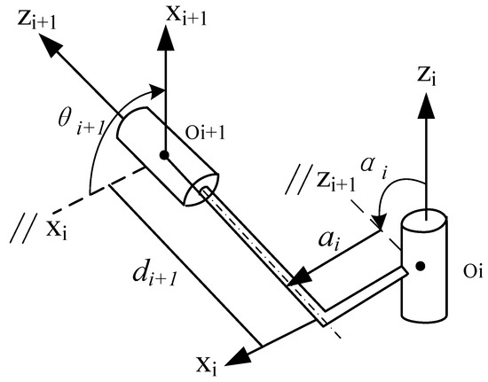
Figure 12.
Schematic diagram illustrating the definition of D-H parameters.
: The distance along xi from zi to zi+1, describing the length of the link;
: The angle around xi from zi to zi+1, describing the twist angle of the link;
: The distance along zi+1 from xi to xi+1, describing the offset between joints;
: The angle around zi+1 from xi to xi+1, describing the rotation angle of the joint.
The homogeneous transformation matrix Ti,i+1 from the joint local coordinate system O-xiyizi to the joint local coordinate system O-xi+1yi+1zi+1 is expressed as:
2.2.2. Closed-Loop Equations and Degree of Freedom Analysis
For a single closed-loop mechanism with nR, the closed-loop equation can be expressed as:
Here, denotes the 4 × 4 identity matrix. The planar schematic of the 10R folding mechanism is presented in Figure 2, showing its ten revolute joints. The specific parameter data as shown in Table 1. The corresponding geometric parameters are listed in Equation (13), Its free state is shown in Figure 13.

Table 1.
D-H parameters of the 10R folding closed-loop mechanism.
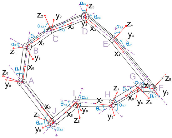
Figure 13.
10R folding closed-loop mechanism D-H parameter relationship diagram. (Red represents the link coordinate system).
After calculation, the transition matrix between joints is obtained as follows:
Therefore, Equation (15) can be derived. Due to its complexity and the large number of variables involved, the explicit form of this equation is omitted here. Using MATLAB R2023b, the equation can be implemented to facilitate numerical computation. By inputting specific variable values, the remaining parameters can be obtained, enabling the derivation of the mechanism’s configuration. MATLAB core code, see Supplementary Materials.
2.3. Higher-Order Kinematic Analysis of Three Types of Singular Configurations
This section presents a higher-order kinematic analysis of three representative singular configurations (denoted as Configurations I, II, and III). It elucidates the evolution of their DOF and the characteristics of their motion branches. Furthermore, configuration transition paths and key coordination mechanisms are discussed in detail.
2.3.1. Higher-Order Kinematic Analysis of Singular Configurations I
The 10R folding mechanism exhibits Singular Configuration I. As illustrated in Figure 13, the orientation of all ten revolute joints, with rotation axes mathematically described by Equation (16).
According to advanced kinematic theory, the first-order kinematic constraints of a closed-loop mechanism can be described by Equation (17), where the Jacobian matrix (Equation (18)) and the angular velocity vector (Equation (18)) must satisfy a linear relationship. Substituting Equations (18) and (19) into Equation (17) yields Equation (20), which can be solved to obtain the first-order constraint solution (Equation (21)) and its constraint solution space (Equation (22)).
The second-order kinematic constraint equations of a closed-loop mechanism are obtained by taking the simultaneous time derivative of its first-order kinematic constraint equations, i.e.,
In this expression, denotes the column vector of angular accelerations for all rotary-joint axes. For the 10R variable-cell folding mechanism, is defined by Equation (24), in which represents the time derivative of the Jacobian matrix. The subvector is then computed according to Equation (25).
The calculation procedure used in Equation (25) is detailed in Equation (26):
In Equation (26), vectors and are the main parts of rotor , and vectors and are the auxiliary parts of rotor . Substituting Equation (25) into Equation (23) yields:
The second-order acceleration equation of a closed loop can be regarded as a non-homogeneous linear equation system. The conditions for the equation system to have a solution are: , where the Jacobian matrix is:
Substituting Equations (19) and (26) into (25) yields −SL, as shown in Equation (29):
Place the in Equation (29) and the Jacobian matrix into the extended matrix to form Equation (30).
Among them, , , , and are:
After analysis, if the ranks of the matrices are equal, then A should be 0. Substituting the kinematic first-order solution space Equation (20) into the equation A = 0, we obtain the following solution:
The configuration evolution process of the two motion branches as shown in Figure 14, and their kinematic characteristics are analyzed as follows:
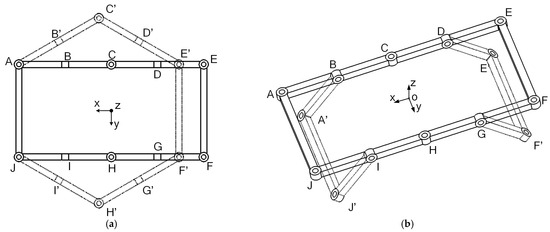
Figure 14.
Two motion branches of singular configuration I (a) Motion branch 1 of singular configuration I (b) Motion branch 2 of singular configuration I.
- (a)
- When , the motion branch 1 of singular configuration I can be obtained, as shown in Figure 14a. This set of solution relationships corresponds to the four rotational pairs B, D, G, and I remaining stationary, while the six rotational pairs A, C, E, F, H, and J rotate. At this point, the mechanism is a planar six-bar mechanism composed of the linkages AC, CE, EF, FH, HJ, and JA, with three DOF.
- (b)
- When , the motion branch 2 of singular configuration I can be obtained, as shown in Figure 14b. In this set of motion states, the six rotating joints A, C, E, F, H, and J remain stationary, the AB, AJ, and IJ links rotate around the BI axis, the DE, EF, and FG links rotate around the DG axis, and the BCD and GHI links remain stationary, with a degree of freedom of 2.
This configuration achieves initial reconstruction from a rectangular structure to a hexagonal structure through motion branches 1 and 2. It has the highest degree of freedom and can be used for large-range bending operations, constituting the most flexible working form of the robot. Singular configuration I serves as the initial state for configuration switching, exhibiting favorable deformability and path accessibility.
2.3.2. Higher-Order Kinematic Analysis of Singular Configurations II
The schematic diagram of the singular configuration II structure is shown in Figure 15. Frame 1, formed by joints A, B, C, D, and E, and frame 2, formed by joints F, G, H, I, and J, are in a parallel state. Frame 3 is formed by joints E, F, J, and A. Frame 1 and frame 2 are parallel to each other, and frame 3 is located between frame 1 and frame 2 and is perpendicular to frame 1 and frame 2. In this configuration, joints C and H are locked, and the BD and IG rods form a rigid support, enabling the structure to rotate freely around a common axis.
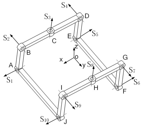
Figure 15.
Schematic diagram of the singular configuration II structure.
The rotation axes of the 10 joints in this configuration are aligned with the coordinate axes as shown in Figure 15. The rotation quantities of the 10 joints are expressed in Equation (36):
According to the rotor expression, this configuration has no common constraint rotor system. The order is 6, the degree of freedom is 4, and its Jacobian matrix is:
Similarly to the higher-order kinematic approach for the singular configuration I, the first-order kinematic analysis results are obtained by substituting Equations (19) and (37) into Equation (17) to yield Equation (38):
Solving the first-order kinematic Equation (38) yields Equation (39). Based on the closed-loop mechanism, the first-order constraint solution space is given by Equation (40):
The principles and process of analyzing the second-order kinematics of this configuration are the same as those for singular configuration I, so they will not be repeated here. Differentiating the first-order kinematic Equation (38) for singular configuration II and calculating yields:
Among them, A, B, C, D, E, and F are:
From Equation (37), analysis shows that the rank of the Jacobian matrix is 5. The second-order solution requires , so E and A in Equation (41) are opposite numbers. From the first-order solution space, we can obtain: . Therefore, we obtain the angular velocity relationship as follows:
Analysis shows that joints 3 and 8 cannot rotate in this configuration, i.e., , so:
The schematic diagram of the two motion branches is as shown in Figure 16. The transformation process of each motion branch is described as follows:
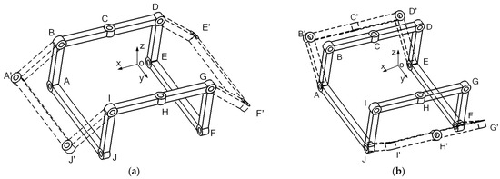
Figure 16.
Two movement branches of singular configuration II (a) Singular configuration II movement branch 1 (b) Singular configuration II movement branch 2.
- (a)
- When , motion branch 1 (Figure 16a) is obtained, as shown in Figure 16a. This set of solution relationships corresponds to the four rotational pairs of joints A, C, E, F, H, and J being fixed in place, the axes of joints B and I coinciding, the axes of joints D and G coinciding, and the links of the mechanism rotating around the BI axis and DG axis, causing the mechanism to unfold in a plane with 2 DOF.
- (b)
- When , motion branch 2 (Figure 16b) is obtained, as shown in Figure 16b. This set of solution relationships corresponds to the rotation pairs B, C, D, G, H, and I remaining stationary, the axes A and E, and the axes D and G coinciding. The links of the mechanism rotate around the axes AE and FJ, causing the mechanism to unfold in the plane, with a degree of freedom of 2.
Configuration II provides a stable hexagonal structure ideal for omnidirectional locomotion and symmetrical deformation. It has low DOF and high configuration stiffness, making it suitable for stable movement in areas with high curvature on the front surface of wind turbine blades. Configuration II often serves as an intermediate state in complex path transitions.
2.3.3. Higher-Order Kinematic Analysis of Singular Configurations III
The singular configuration III is shown in Figure 17. Its structural features are as follows: joints A, C, E, F, H, and J serve as the six vertices of a regular hexagon, while the axes of joints B and G coincide and are perpendicular to the sides AC and FH. Similarly, the axes of joints D and I coincide and are perpendicular to the CE and HJ edges. This configuration allows folding around the BG and DI axes or rotating around the six vertices A, C, E, F, H, and J. The following section conducts a theoretical analysis to examine the relationships between the motion parameters of the joint axes.
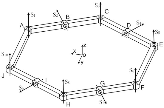
Figure 17.
Schematic diagram of singular configuration III.
For the singular configuration III of the 10R folding variable cell folding mechanism shown in Figure 17, the rotation axes of its 10 rotating joints can be represented as:
The common constraint rotor system shown in Equation (52) is derived based on the rotor expression. This configuration has a common constraint rotor system with an order of 5, a degree of freedom coefficient b = 5, and 5 DOF. Its Jacobian matrix is:
Similarly to the higher-order kinematic approach for the singular configuration I, the first-order kinematic analysis is obtained by substituting Equations (19) and (53) into Equation (17):
Solving the first-order kinematic Equation (54) yields Equation (55). Based on the closed-loop mechanism, the first-order constraint solution space is given by Equation (48):
The principles and process of second-order kinematic analysis for this configuration are the same as those for singular configuration I. The first-order kinematic Equation (54) for singular configuration III is differentiated and calculated, and the results are shown in Equation (57).
Among them, A, B, C, D, E, and F are:
From Equation (53), analysis shows that the rank of the Jacobian matrix is 5. For a second-order equation to have a solution, must be satisfied, which means that in Equation (57), i.e.
Case 1: . This case can be further divided into three sub-cases:
- .
Case 2: . This case is further divided into two sub-cases:
- ;
- ;
The diagram showing the transformation of the five motion branches is shown in Figure 18. The transformation process of each motion branch is described as follows:
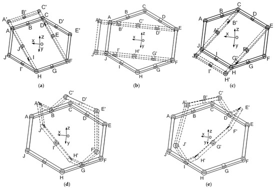
Figure 18.
Singular Configuration III Motion Branch (a) Singular Configuration III Motion Branch 1 (b) Singular Configuration III Motion Branch 2 (c) Singular Configuration III Motion Branch 3 (d) Singular Configuration III Motion Branch 4 (e) Singular Configuration III Motion Branch 5.
- (a)
- When , motion branch 1 is obtained, as shown in Figure 18a. This set of solution relationships corresponds to the six rotating pairs B, D, F, G, H, and I being fixed in place, the rotational speeds of pairs A and F being equal, the rotational speeds of pairs C and H being equal, the rotational speeds of E and J being equal, and the sum of the rotational speeds of C and F being equal in magnitude but opposite in direction to the rotational speed of E, and the sum of the rotational speeds of A and H being equal in magnitude but opposite in direction to the rotational speed of J, with 3 DOF.
- (b)
- When , motion branch 2 is obtained, as shown in Figure 18b. This set of solution relationships corresponds to the six rotating pairs B, D, G, I, E, and F being fixed in place, the rotational speeds of rotating pairs A and F being equal, the rotational speeds of rotating pairs C and H being equal, the rotational speeds of E and J being equal, and the sum of the rotational speeds of A and E being equal in magnitude but opposite in direction to the rotational speed of C, and the sum of the rotational speeds of F and J being equal in magnitude but opposite in direction to the rotational speed of H, with 3 DOF.
- (c)
- When , motion branch 3 is obtained, as shown in Figure 18c. This set of solution relationships corresponds to the six rotating pairs B, D, G, I, C, and E being fixed and stationary, the rotational speeds of the rotating pairs A and F being the same, the rotational speeds of the rotating pairs C and H being the same, the rotational speeds of E and J being the same, and the sum of the rotational speeds of E and H being equal in magnitude and opposite in direction to the rotational speed of F, and the sum of the rotational speeds of C and J being equal in magnitude and opposite in direction to the rotational speed of A, with 3 DOF.
- (d)
- When , motion branch 4 is obtained, as shown in Figure 18d. This set of solution relationships corresponds to the eight rotating pairs A, C, D, E, F, H, I, and J being fixed, with the mechanism rotating around the BG joint axis, resulting in 1 degree of freedom.
- (e)
- When , motion branch 5 is obtained, as shown in Figure 18d. This set of solution relationships corresponds to the eight rotating joints A, B, C, E, F, G, H, and J being fixed, with the mechanism rotating around the DI joint axis, resulting in 1 degree of freedom.
Configuration III enables symmetrical flipping about multiple axes, particularly suitable for flipping operations in the blade leading and trailing edge regions blades. Its structure provides rotational freedom along the BG and DI axes, laying the dynamic foundation for continuous transitions across three-dimensional terrain.
The motion characteristics of the 10R folding closed-loop mechanism can be characterized by a configuration space topology diagram. As shown in Figure 19, the mechanism has three singular configurations, which divide the configuration space into seven continuous motion paths, each with a degree of freedom ≥2, and achieve path connectivity at the singular points. The figure intuitively marks the correspondence between the singular configurations and the associated motion paths with arrows.
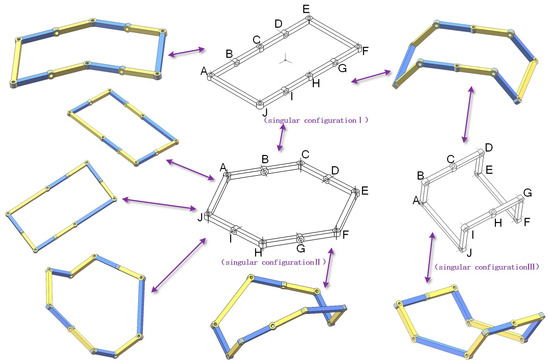
Figure 19.
10R folding mechanism configuration diagram(Color-coded joints).
2.4. Configuration Switching Analysis
The variable-cell climbing robot exhibits dynamic reconfiguration capabilities, enabling adaptive transitions among distinct morphological configurations and locomotion modalities. Having analyzed the conditions required for trunk reconfiguration in the previous section, we now integrate leg coordination to elucidate the coupling mechanism between gait patterns and trunk adjustments. This integrated approach enables coordinated control of multimodal motion throughout the configuration-switching process.
2.4.1. Switch from Singular Configuration I to Singular Configuration II
To determine the complete switching path of the robot, the initial state of the robot is singular configuration I. By combining research on the singular configuration motion branches of the 10R folding mechanism, the switching process from configuration I to singular configuration II is analyzed, as shown in Figure 20.
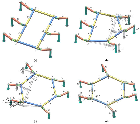
Figure 20.
Process of conversion from singular configuration I to singular configuration II(Color-coded joints) (a) Singular configuration I (b) Transition state I (c) Transition state II (d) Singular configuration II.
Figure 20a shows the initial state of singular configuration I, which has five DOF, with drive motors distributed at the A, E, F, B, and G rotational joints. Transitioning to singular configuration II involves two intermediate states (Figure 20b,c), ultimately forming the configuration II shown in Figure 20d.
Neglecting rotations about axes BI and DG, the trunk metamorphoses from rectangular topology AEFJ to hexagonal topology ACEFHJ. The robot employs vacuum suction cups for blade adhesion, maintaining operational stability. During the transition, Legs L1–L4 remain adhered, while L5 and L6 lift; the motor at joint F rotates until angle EFH reaches 120°, and linkages FH, HJ, and JA adjust synchronously. Simultaneously, the motor at the base segment L4-1 of leg L4 rotates to α4, the motor at L4-2 rotates to β4, and the joint motor at L4-3 rotates to γ4, completing transition state one.
Switch from transition state 1 to transition state 2: Legs L1, L4, L5, and L6 remain attached, while legs L2 and L3 are raised. At this point, the joint motor at joint E rotates to an angle CEF of 120°, and the linkages JA, AC, and CE follow suit. Simultaneously, the joint motor at the base segment L1-1 of leg L1 rotates to position α1, the joint motor at L1-2 rotates to position β1, and the joint motor at L1-3 rotates to position γ1. The transition to state two is complete.
Transition from transition state II to singular configuration II: Legs L2, L3, L4, L5 remain adsorbed, while legs L1 and L6 are raised. At this point, the joint motor at joint A rotates to an angle JAC of 120°, and the link CAJH follows the transformation. Since the angle change in the joint motor on leg L2 is relatively small during this transformation, it can be offset by the ball-and-socket structure with 30 DOF at the end, so the joint motor on leg L2 remains unchanged. Thus, the configuration transitions from singular configuration I to singular configuration II.
2.4.2. Switch from Singular Configuration I to Singular Configuration III
The wind turbine blade climbing robot moves across the surface of wind turbine blades, which are predominantly irregular, convex, curved surfaces. Therefore, the process of switching the robot from singular configuration I to singular configuration III facilitates its movement across curved surfaces and enables it to traverse the leading and trailing edges of the blades, thereby achieving all-terrain mobility across the surface of wind turbine blades. The process of the climbing robot moving from the blade surface toward the leading edge and crossing over the leading edge constitutes the completion cycle of the transition from singular configuration I to singular configuration III. The joint numbers and their corresponding positions on the blade are illustrated in Figure 21.
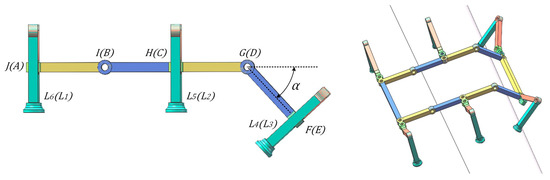
Figure 21.
Transition configuration I conversion transition configuration I process.
From Singular Configuration I to Transition Configuration III: As the climbing robot approaches the leading edge of the blade, the curvature of the blade increases as it gets closer to the leading edge due to its irregular surface. At this point, the joint motor at joint G of the robot’s body begins to rotate in response to changes in the blade’s curvature, with a rotation angle of α, where α ranges from 0 to 45°.
From Transition Configuration I to Transition Configuration II: As the robot moves toward the leading edge, as shown in Figure 22, the joint motor at joint B also responds to blade curvature variations, rotating by an angle β. When the DG axis crosses the leading edge boundary line, the base segments of legs L1, L2, L5, L6 remain adhered, while legs L3 and L4 lift. Joint motor G rotates to a position where α is 90°, and the basal segment motors of legs L3 and L4 rotate to a position where the legs are parallel to the longitudinal direction of the trunk. The femur and tibia motors are then adjusted until they adhere to the blade.
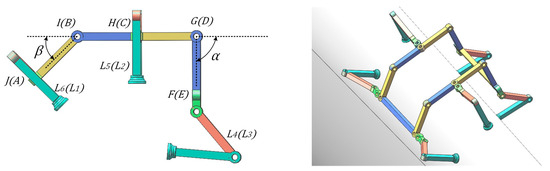
Figure 22.
Transition configuration I conversion transition configuration II process.
From transition state II to singular configuration III: the robot climbs over the leading edge of the blade, as shown in Figure 23, until the CH line coincides with the leading edge boundary line. Legs L2 and L5 cross over both sides of the leading edge and adhere, while L3 and L4 remain adhered. Legs L1 and L6 are lifted, and the joint B motor rotates to β = 90°, with L1 and L6 adjusted to be parallel to the trunk, and the femur and tibia motors rotate until L1 and L6 adhere to the blade. At this point, the transition from singular configuration I to singular configuration III is complete. After singular configuration III, the robot transitions to wheel-and-blade contact, enabling rapid movement along the leading edge of the blade.
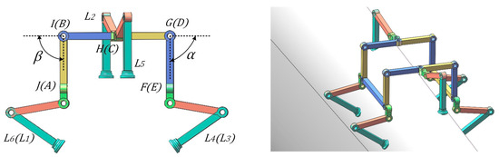
Figure 23.
Transition from transition configuration II to transition configuration III.
3. Prototype Assembly and Experimentation
We constructed an initial prototype of the wind turbine blade climbing robot and validated its design feasibility and operational reliability through a series of experiments. The prototype features a modular architecture that integrates a trunk support structure, a wheel–leg hybrid mobility system, a power supply, and a control unit, enabling multi–degree-of-freedom actuation and intelligent control.
3.1. Prototype Construction
The prototype is a scaled-down version, as shown in Figure 24. The structural design of this robot can be divided into two core components: the main frame and the mobility system, which specifically includes the trunk support assembly, composite wheel-leg structure, power supply unit, and central control system. The trunk components of the prototype are made of aluminum alloy through bending and welding, while some components subjected to lower stress are made of carbon fiber materials. The trunk section includes 10 rotating joints, but its actual degrees of freedom are 5, achieved through 5 servomotors at the joints. The wheel-leg module’s basal segment, tibial segment, and wheel frame are made of aluminum alloy sheet metal and welded components, while the femoral segment is made of carbon fiber material via CNC machining, and some irregularly shaped components are produced using 3D printing. The suction cups at the foot tips use ZP3E-TF80BM-AL16 double-layer suction cups, with the ankle joint having a 30° range of motion. A tension spring is added at this point to increase the stiffness of the ankle joint when ankle movement is not required. All three leg joints are driven by servo motors. The clamping wheels and load-bearing wheels are made of nylon material via CNC machining. The robot’s battery module uses a dual-power supply system, with two batteries each mounted on separate load platforms.
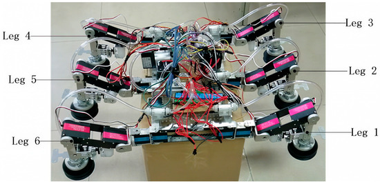
Figure 24.
Small prototype diagram.
A scaled-down prototype was fabricated (see Figure 24), measuring 500 mm × 400 mm × 300 mm and weighing 10 kg. Its chassis is constructed from aluminum alloy and carbon-fiber composites to maximize the strength-to-weight ratio. The trunk features ten rotary joints—five of which provide active DOF via dedicated servomotors—while each leg is driven by digital servos rated at 60 kg·cm and 30 kg·cm torque to ensure high-torque output. In total, 23 servomotors are integrated, and the system is powered by a dual-battery package. The modular architecture, with standardized interfaces between components, achieves a careful balance of lightweight construction and structural integrity. See Table 2 for specific parameters.
Table 2.
Prototype parameter.
3.2. Control System Design
The control architecture comprises an STM32F103C8T6 main controller, a 32-channel servo driver board, a vacuum generation and regulation unit, and an integrated sensor suite. The main controller orchestrates all servomotor commands and processes incoming sensor data, communicating with peripheral modules via serial interfaces. The vacuum subsystem—governed by a relay—engages and disengages the adhesion mechanism on demand. Meanwhile, an infrared distance sensor continuously monitors the robot’s posture and the surrounding environment, enabling real-time adjustments to maintain stable, reliable climbing performance (see Figure 25).
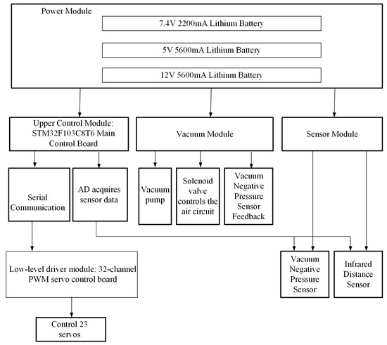
Figure 25.
Architecture of the motion control system.
The control system is built around an STM32F103C8T6 microcontroller, which interfaces via a 32-channel PWM driver to precisely actuate twelve 60 kg·cm and eleven 30 kg·cm digital servos. The microcontroller also manages a vacuum-generation module, a GPY2 infrared distance sensor for real-time posture and environment monitoring, and a 2.4 GHz wireless remote-control receiver. Power is delivered by dedicated 7.4 V, 5 V, and 12 V lithium battery packs, supplying all functional units. This architecture ensures both high flexibility and precise control throughout the robot’s multimodal climbing operations.
The STM32F103C8T6 control mainboard is shown in Figure 26. It has a clock speed of 72 MHz, providing fast processing capabilities. It features 37 GPIO pins, supporting various input/output configurations. It includes 3 general-purpose timers and 1 advanced control timer. Communication interfaces: 2 SPI, 2 I2C, 3 USART, and 1 USB. ADC: 2 12-bit ADCs with 10 channels, supporting analog signal acquisition. Its GPIO pins are used to control the relay for enabling the vacuum system’s start/stop, and its AD pins convert the analog signals from the infrared distance sensor into digital signals. It communicates via serial port with a 32-channel servo controller to control the angle of the robot’s servos.
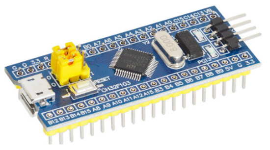
Figure 26.
STM32F103C8T6 Development Board.
The 32-channel PWM servo control board, as shown in Figure 27, uses a high-performance STM32 microcontroller with an ARM Cortex-M core, enabling precise control of servo movement with adjustable speed. It incorporates 6-channel overcurrent protection, significantly reducing the risk of servo motor burnout due to stalling. Additionally, the board includes built-in communication interfaces for joystick/USB/Bluetooth/MP3/TTL serial ports, supporting multiple control methods, and reserves a TTL serial port interface for secondary development. Connect the 32-channel servo control board to the main control board via serial communication.
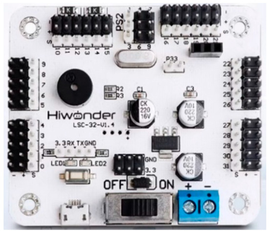
Figure 27.
32-channel servo control board.
The vacuum negative pressure sensor model is DME-A1-A1bar-O1S4C2T1-L2, as shown in Figure 28. Its measurement range is 0~1bar, which meets the usage requirements. Its output signal is a voltage signal, and the communication method is I2C.
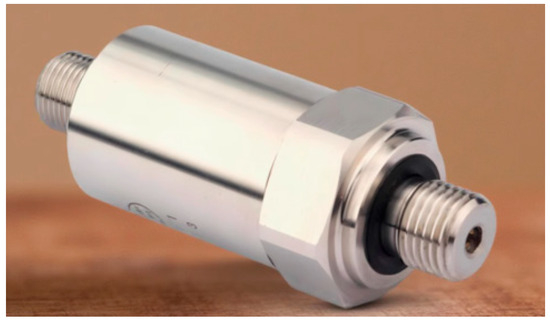
Figure 28.
Vacuum negative pressure sensor.
The infrared distance sensor GPY2 is shown in Figure 29. It continuously emits infrared light with a wavelength of 950 nanometers through its built-in infrared light-emitting diode. When the emitted infrared light is not reflected by an obstacle or the reflection intensity is too weak, the phototransistor does not conduct. Only when the intensity of the reflected infrared light is sufficient and successfully received by the phototransistor does the phototransistor conduct and generate an output signal. In operating mode, the collector current of the phototransistor is approximately 1 milliampere. The effective operating range of the GPY2 distance sensor is 1 to 15 cm.
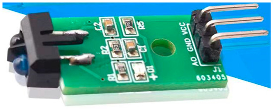
Figure 29.
Infrared distance sensor.
3.3. Prototype Configuration Switching Experiment
To validate the structural reconfiguration capability of the wind turbine blade climbing robot in multi-configuration environments, experiments were conducted for switching from Singular Configuration I to Singular Configuration II, and from Singular Configuration I to Singular Configuration III, as shown in Figure 30. The experiment utilized a scaled prototype. The robot initially resided in Singular Configuration I. Upon triggering the switching command, the control system actuated the corresponding joints to complete the angular adjustments, progressively transitioning into Singular Configuration II. Infrared rangefinders monitored attitude changes in real-time, with the leg drives providing dynamic compensation, ultimately completing the configuration switch.
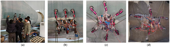
Figure 30.
Prototype in different configurations: (a) Wind turbine blade scenario testing (b) Singular configuration I, (c) Singular configuration II (d) Singular configuration III.
To further quantitatively validate the performance, the switching process was recorded to take approximately 6.3 s. During mobility experiments, the robot achieved uniform linear crawling with a maximum speed of 125 mm/s and a minimum step control of 20 mm. The maximum attitude deviation angle during configuration switching did not exceed 3.2 degrees. Experimental results demonstrate that the robot possesses excellent configuration-reconstruction capability, attitude stability, and adaptability to complex curved surfaces, effectively laying the groundwork for wind turbine blade maintenance applications.
4. Discussion
This study successfully designed and implemented a wind turbine blade climbing robot based on a 10R-Folding variable cell mechanism. By employing configuration-adaptive switching and a wheel-leg composite mobility strategy, the robot achieved significantly enhanced motion adaptability and operational efficiency in environments characterized by high curvature and nonlinear surfaces. Experimental results demonstrate that the robot can stably switch between rectangular and hexagonal configurations, with a switching time of approximately 6.3 s, a single-joint response time of 0.4 s, a maximum movement speed of 125 mm/s, and attitude deviation controlled within 3.2°, validating the effectiveness and engineering feasibility of the variable-cell mechanism in complex curved surface climbing. High-order kinematic analysis based on rotor theory clearly reveals the changes in degrees of freedom and the mechanism of motion branch transitions under three typical singular configurations, providing theoretical support for the robot’s gait planning and configuration control.
Despite the above achievements, this study still has limitations. As a first-generation innovative prototype, the robot’s structural design and material selection still have room for optimization, and its overall weight and power consumption need to be further reduced to improve its continuous operation capability. Current experiments are primarily conducted in laboratory environments, and systematic testing has not yet been conducted in the complex real-world environments of wind turbine blades (such as strong winds, high humidity, and surface contamination), leaving environmental adaptability and reliability to be validated. Additionally, the robot has not yet integrated fault detection and diagnosis functions, and it currently lacks the ability to autonomously identify damage or abnormalities during actual maintenance tasks.
5. Conclusions
This paper addresses the maintenance and operation requirements of large wind turbine blades by designing a climbing robot based on a 10R-Folding variable-cell mechanism, enabling adaptive climbing and multi-modal motion on complex curved surfaces. The main achievements include: proposing a variable-cell trunk structure with three types of singular configurations, effectively supporting the robot’s stable adhesion, efficient movement, and smooth traversal on high-curvature blade surfaces such as the leading edge; Based on the modified Grubler–Kutzbach criterion and rotor theory, a high-order kinematic model was established for the system, revealing the evolution of degrees of freedom and the mechanism of motion branch transitions under singular configurations, providing a theoretical foundation for configuration planning and control; A physical prototype integrating wheel-leg drive, vacuum adhesion, and multi-sensor control was developed. Experimental validation confirmed the robot’s configuration switching capability, motion performance, and attitude stability, demonstrating the design’s excellent engineering feasibility.
Future work will focus on the following areas: further structural lightweighting and power system optimization to enhance the robot’s load capacity and endurance; integration of multi-modal perception and autonomous navigation algorithms to achieve online identification and localization of blade damage; and system testing in real wind farm environments to improve the robot’s adaptability and reliability under complex conditions such as high wind speeds, dust, and slippery surfaces.
Supplementary Materials
The following supporting information can be downloaded at: https://www.mdpi.com/article/10.3390/machines13090808/s1, Two segments of MATLAB core code (bihuanfangcheng.m and Sl_likuohao.m) used for theoretical analysis and numerical computation are submitted as supplementary materials, corresponding respectively to the closed-loop equation solving and spinor Lie bracket calculation sections in the main text.
Author Contributions
Conceptualization, X.S. and C.Y.; methodology, X.S. and M.S.; validation, M.S. and C.Y.; formal analysis, X.S. and H.L.; investigation, X.S.; resources, X.S.; data curation, C.Y. and M.S.; writing—original draft preparation, C.Y. and M.S.; writing—review and editing, C.Y. and H.L.; visualization, X.S.; supervision, H.L.; project administration, H.L.; funding acquisition, X.S. All authors have read and agreed to the published version of the manuscript.
Funding
This work was funded by the “Production, Education, Research, and Application” Innovative Talent Training and Innovation Ability Cultivation Service Project at Yanshan University (Approval No. x2024154).
Data Availability Statement
The original contributions presented in this study are included in the article. Further inquiries can be directed to the corresponding author.
Conflicts of Interest
The authors declare no conflicts of interest.
References
- Zhu, J.; Zhu, Y.; Zhang, P. Review of advancements in wall climbing robot techniques. Frankl. Open 2024, 8, 100148–100156. [Google Scholar] [CrossRef]
- Liu, X.; Wang, Z.; Wu, J.; Wu, H.; Zhang, H. Trajectory Tracking of a Wall-Climbing Cutting Robot Based on Kinematic and PID Joint Optimization. Machines 2025, 13, 229. [Google Scholar] [CrossRef]
- Zhang, X.; Wu, Y.; Liu, H.; Zhong, D. Design and Analysis of a Wheel-Footed Magnetic Adhesion Obstacle-Crossing Wall-Climbing Robot. Trans. Chin. Soc. Mech. Eng. 2024, 60, 248–261. [Google Scholar] [CrossRef]
- Zheng, Y.; Liu, H. Design and Analysis of an Adaptive Legged Wall-Climbing Robot. Mech. Des. 2021, 38, 105–112. [Google Scholar] [CrossRef]
- Wang, Y.; Zhang, X.; Zhang, M.; Sun, L. Design and Analysis of a Modular Flexible Climbing Robot with Adaptive Curvature Facades. J. Mech. Eng. 2021, 57, 10. [Google Scholar] [CrossRef]
- Yang, P.; Zang, J.; Huang, B.; Zhao, J. Electromagnetically Adhering and Self-Inductive Sensing Claw for Continuum Climbing Robots: Design, Control, and Applications. Adv. Intell. Syst. 2025, 7, 2400800. [Google Scholar] [CrossRef]
- Shi, Y.; Gong, Z.; Tao, B.; Yin, Z.; Ding, H. An Active Compliance Adsorption Method for Climbing Machining Robot on Variable Curvature Surface. IEEE/ASME Trans. Mechatron. 2023, 28, 1127–1136. [Google Scholar] [CrossRef]
- Liu, J.-H.; Padrigalan, K.E. The Kinematic Analysis of a Wind Turbine Climbing Robot Mechanism. Appl. Sci. 2022, 12, 1210. [Google Scholar] [CrossRef]
- Padrigalan, K.E.; Liu, J.-H. A Wind-Turbine-Tower-Climbing Robot Prototype Operating at Various Speeds and Payload Capacity: Development and Validation. Appl. Sci. 2023, 13, 1381. [Google Scholar] [CrossRef]
- Liu, J.H.; Padrigalan, K. Design and Development of a Climbing Robot for Wind Turbine Maintenance. Appl. Sci. 2021, 11, 2328. [Google Scholar] [CrossRef]
- Gao, H.; Han, H. Design and Analysis of a Wall-Climbing Robot for Wind Turbines with Wheeled Legs. Mech. Des. 2023, 40, 101–106. [Google Scholar] [CrossRef]
- Zhang, Y.; Hu, X.-L.; Wang, K.-M.; Huang, H. Design and Analysis of a Wind Turbine Blade Inspection Robot. J. Eng. Des. 2025, 32, 159–168. [Google Scholar] [CrossRef]
- Chen, D.; Yu, G.; Huang, S. Complete Coverage Path Planning for Wind Turbine Blade Wall-Climbing Robots Based on Bio-Inspired Neural Networks and Energy Consumption Model. Machines 2025, 13, 180. [Google Scholar] [CrossRef]
- Dai, J.S.; Jones, J.R. Mobility in Metamorphic Mechanisms of Foldable/Erectable Kinds. J. Mech. Des. 1999, 121, 375–382. [Google Scholar] [CrossRef]
- Yang, H.; Wei, G.; Ren, L. A Novel Soft Actuator: MISA and Its Application on the Biomimetic Robotic Arm. IEEE Robot. Autom. Lett. 2023, 8, 2373–2380. [Google Scholar] [CrossRef]
- Xu, Y.; Luo, Z.; Shang, J.; Wei, G.; Zhu, Y.; Bai, X. Design and analysis of a concentrated-driven bionic-leg capable of omnidirectional legged locomotion based on 3-Dimensional dual-parallelogram-linkages. Proc. Inst. Mech. Eng. Part C. J. Mech. Eng. Sci. 2024, 238, 459–478. [Google Scholar] [CrossRef]
- Wang, S.; Huang, H.; Jia, G.; Li, B.; Guo, H.; Liu, R. Design of a novel three-limb deployable mechanism with mobility bifurcation. Mech. Mach. Theory 2022, 172, 104789. [Google Scholar] [CrossRef]
- Jia, G.; Huang, H.; Wang, S.; Li, B. Type synthesis of plane-symmetric deployable grasping parallel mechanisms using constraint force parallelogram law. Mech. Mach. Theory 2021, 161, 104330. [Google Scholar] [CrossRef]
- Zhang, W.; Liu, F.; Lv, Y.; Ding, X. Design and analysis of a metamorphic mechanism for automated fibre placement. Mech. Mach. Theory 2018, 130, 463–476. [Google Scholar] [CrossRef]
- Liu, F.; Zhang, W.; Shang, J.; Yi, M.; Wang, S.; Ding, X. A Planar Underactuated Compaction Mechanism with Self-Adaptability for Automated Fiber Placement Heads. Aerospace 2022, 9, 586. [Google Scholar] [CrossRef]
- Suthar, B.; Jung, S. Design and Bending Analysis of a Metamorphic Parallel Twisted-Scissor Mechanism. J. Mech. Robot. 2021, 13, 040901. [Google Scholar] [CrossRef]
- Sun, H.; Sun, W.; Chen, B.; Hou, Y.; Kong, J. Design, Analysis, and Experiment of a Scissor-Shaped Deployable Metamorphic Hand. J. Mech. Robot. 2022, 14, 060909. [Google Scholar] [CrossRef]
- Qin, J.; Yu, C.; Sun, Z.; Cao, L. A Novel Method for Type Synthesis of Parallel Mechanism Without Parasitic Motion Based on 2R1T Parallel Mechanism with Rotational Bifurcation. Chin. J. Mech. Eng. 2022, 35, 191–202. [Google Scholar] [CrossRef]
- An, W.; Wei, J.; Lu, X.; Dai, J.S.; Li, Y. Geometric Design-based Dimensional Synthesis of a Novel Metamorphic Multi-fingered Hand with Maximal Workspace. Chin. J. Mech. Eng. 2021, 34, 41. [Google Scholar] [CrossRef]
- Dong, K.; Li, D.; Xue, X.; Xu, C.; Wang, H.; Gao, X. Workspace and Accuracy Analysis on a Novel 6-UCU Bone-attached Parallel Manipulator. Chin. J. Mech. Eng. 2022, 35, 35. [Google Scholar] [CrossRef]
- Tang, Z.; Wang, K.; Spyrakos-Papastavridis, E.; Dai, J.S. Origaker: A Novel Multi-Mimicry Quadruped Robot Based on a Metamorphic Mechanism. J. Mech. Robot. 2022, 14, 060907. [Google Scholar] [CrossRef]
- Wang, K.; Hou, Y.; Sun, W.; Hou, Y. Multi-posture mechanical analysis of a variable-cell hand-claw climbing robot. Mech. Des. Manuf. 2023, 192–196. [Google Scholar] [CrossRef]
- Pan, Y.; Zhang, L.; Mei, D.; Tang, G.; Ji, Y.; Tan, K.; Wang, Y. Gait and simulation analysis of quadruped crawling robot based on metamorphic structure. Ind. Robot. Int. J. Robot. Res. Appl. 2023, 51, 91–104. [Google Scholar] [CrossRef]
- Guan, Y.; Zhuang, Z.; Zhang, C.; Tang, Z.; Zhang, Z.; Dai, J.S. Design and Motion Planning of a Metamorphic Flipping Robot. Actuators 2022, 11, 344. [Google Scholar] [CrossRef]
- Han, Y.; Guo, W.; Zhao, D.; Li, Z. Multi-mode unified modeling and operation capability synergistic evaluation for the reconfigurable legged mobile lander. Mech. Mach. Theory 2022, 171, 104714. [Google Scholar] [CrossRef]
- Zhao, D.; Liu, J.; Yang, P.; Cui, T.; Wu, D.; Zhang, L. Modeling and stability control of steering and reconfiguration motion for wheel-legged metamorphic robot. Proc. Inst. Mech. Eng. Part C J. Mech. Eng. Sci. 2025, 239, 4256–4272. [Google Scholar] [CrossRef]


Disclaimer/Publisher’s Note: The statements, opinions and data contained in all publications are solely those of the individual author(s) and contributor(s) and not of MDPI and/or the editor(s). MDPI and/or the editor(s) disclaim responsibility for any injury to people or property resulting from any ideas, methods, instructions or products referred to in the content. |
© 2025 by the authors. Licensee MDPI, Basel, Switzerland. This article is an open access article distributed under the terms and conditions of the Creative Commons Attribution (CC BY) license (https://creativecommons.org/licenses/by/4.0/).