Review

A Review on the Application of Inerters in Vehicle Suspension Systems

1
School of Automotive and Traffic Engineering, Jiangsu University, Zhenjiang 212013, China
2
Automotive Engineering Research Institute, Jiangsu University, Zhenjiang 212013, China
*
Author to whom correspondence should be addressed.
Machines 2025, 13(9), 779; https://doi.org/10.3390/machines13090779
Submission received: 1 August 2025 / Revised: 25 August 2025 / Accepted: 27 August 2025 / Published: 30 August 2025
(This article belongs to the Special Issue New Journeys in Vehicle System Dynamics and Control)

Abstract

The inerter is a device that produces a force proportional to the relative acceleration of both inerter terminals. When combined with springs and dampers in a vehicle suspension system, it forms an inerter–spring–damper (ISD) suspension. This structure shows significant advantages in improving vehicle ride comfort and road friendliness. This paper systematically reviews research progress on ISD suspension. First, the working principle and structural types of the inerter are introduced. Then, an overview of the breakdown phenomena and nonlinear characteristics of ISD suspension is provided, followed by a systematic analysis of ISD suspension structure designs. Next, the control strategies for ISD suspension are discussed, along with their applications in the automotive field. Finally, the paper outlines the main challenges in current inerter research and explores its potential applications in vehicle suspensions. This work can provide a reference for the development of inerter and ISD suspension technologies.

1. Introduction

The vehicle suspension system is highly vital to a vehicle’s dynamic performance and is a key component of the vehicle chassis. It links the road surface to the vehicle body, with functions that include supporting vehicle weight, absorbing and attenuating vibrations and impacts caused by road irregularities on the frame or body, thereby ensuring a smooth driving experience, stable handling, and a comfortable ride.
Vehicle suspension systems are classified into three primary types: passive, semi-active, and active suspension. The structural form of passive suspension is a spring–damper. It has advantages such as a simple structure and relatively low cost [1,2,3,4]. However, the size of its elastic elements and damping elements cannot be adjusted, resulting in poor road adaptability and the inability to absorb vibration energy passively. To improve suspension performance, replacing passive suspension with adjustable elastic elements and damping elements forms semi-active suspension, which achieves excellent vibration reduction performance by adjusting damping or stiffness. Compared with passive suspension, the vibration isolation performance of semi-active suspension is significantly improved [5,6]. Since the implementation of semi-active suspension is based on a fixed suspension structure, it is challenging to ensure that semi-active suspension consistently achieves optimal performance under various road conditions and vehicle operating conditions. Active suspension incorporates actuators into a passive suspension. Through appropriate control methods, the actuators are driven to output an active force, enabling the real-time control of the vehicle’s vertical movement. This enables the vehicle body to achieve an ideal state under various road conditions and operating conditions [7,8]. However, its high cost means it is mainly used in high-end vehicles.
Although semi-active and active suspensions improve suspension performance, from the perspective of impedance transfer characteristics, the vehicle itself has significant inertia. Meanwhile, the traditional spring–damper suspension structure only contains stiffness and damping characteristics, lacking inertial elements, which makes it challenging to coordinate performance indicators. To optimize suspensions, Scholars applied the dynamic vibration absorber (DVA) from the construction field to vehicle suspensions [9,10], which improved vehicle suspension performance to some extent. However, the essence of the DVA is to use the reaction force generated by mass elements during resonance to tune vibrations. Traditional mass elements are single-terminal mechanical components and cannot be applied to vehicle suspensions like two-terminal springs and dampers. In 2002, Smith coupled inertia within transmission mechanisms and invented a two-terminal mass element, known as the inerter, which replaces traditional single-terminal mass elements [11]. The successful application of mass elements in suspension system design compensates for the lack of mass impedance and forms the ISD suspension structure system.
This paper is organized as follows. In Section 2, the working principles and structural types of mechanical and fluid inerters are introduced. Then, an overview of the nonlinear characteristics and breakdown phenomena of the ISD suspension is provided. In Section 3, a comprehensive analysis of the structural forms of ISD suspension is performed using analytical, synthesis, and structure-immittance methods. In Section 4 and Section 5, the control strategies for ISD suspension and the current development and research progress of its applications in automotive engineering are discussed. In Section 6, a comprehensive summary of research progress in inerters and ISD suspensions is provided, and future directions for the design of inerters and the development of ISD suspensions in automotive engineering applications are outlined. The flowchart of the inerter application is shown in Figure 1.

2. Inerter

2.1. The Fundamental Principle of the Inerter

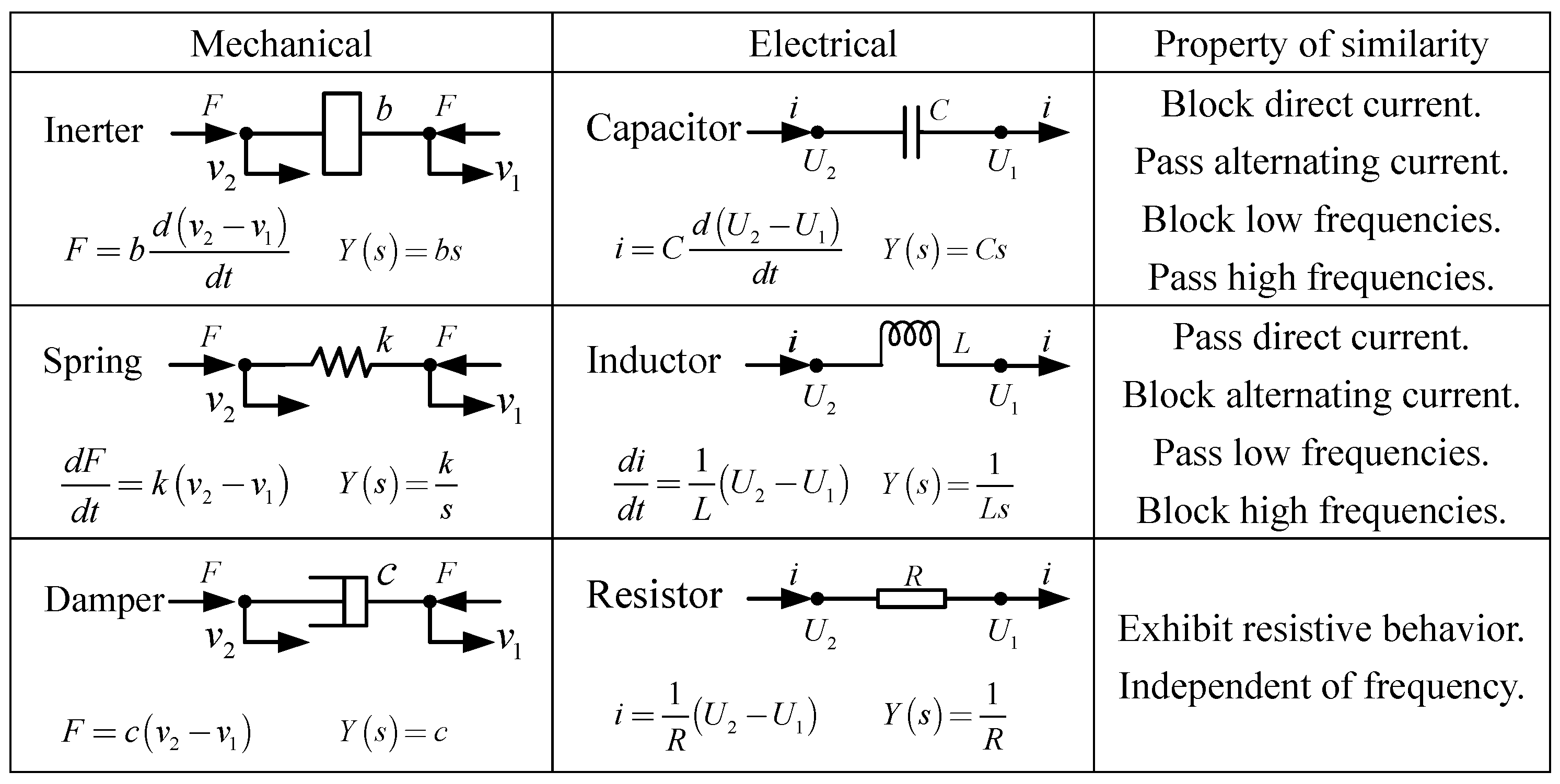
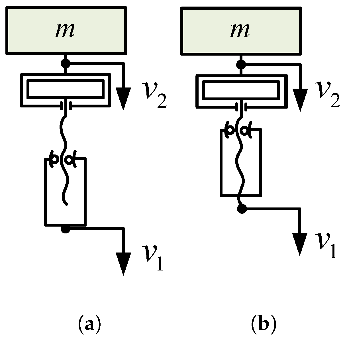
Electromechanical similarity theory refers to the similarity relationship established between mechanical networks and their corresponding electrical networks when their mathematical models have identical transfer functions under harmonic excitation conditions. In this analogy, mass elements correspond to capacitor elements, damping elements correspond to resistor elements, and spring elements correspond to inductor elements. However, because the mass element is a single-terminal element, it could never correspond entirely to the two-terminal capacitor element in electrical networks. It was not until Smith proposed the inerter, which enabled it to form a corresponding relationship with the capacitor, that a new electromechanical similarity theory emerged [12], as shown in Figure 2. This enables the application of mature electrical network design theory to mechanical networks, thereby improving suspension performance.
In Figure 2, the expression of the inerter is as follows.
F = b d v 2 v 1 d t
where F is the force at the two terminals, and v 1 and v 2 are the velocities at the two terminals. b is the inertance.
The key features of the inerter are as follows.
  • Two independent, freely moving terminals;
  • No additional terminals required on an inertial basis;
  • Finite linear stroke with reasonable overall dimension constraints;
  • Small mass and independent inertance.

2.2. Structural Types of Inerters

Since the introduction of the inerter concept, its structural forms have diversified. Based on their implementation methods, they can be classified into mechanical inerters and fluid inerters. Among them, typical representatives of mechanical inerters include the rack-and-pinion inerter, ball-screw inerter, and ball-screw mechatronic inerter. Typical representatives of fluid inerters include the hydraulic motor inerter, hydraulic piston inerter, hydraulic electric inerter, fluid inter, hydraulic controllable inerter, and memory inerter.

2.2.1. Rack-and-Pinion Inerter

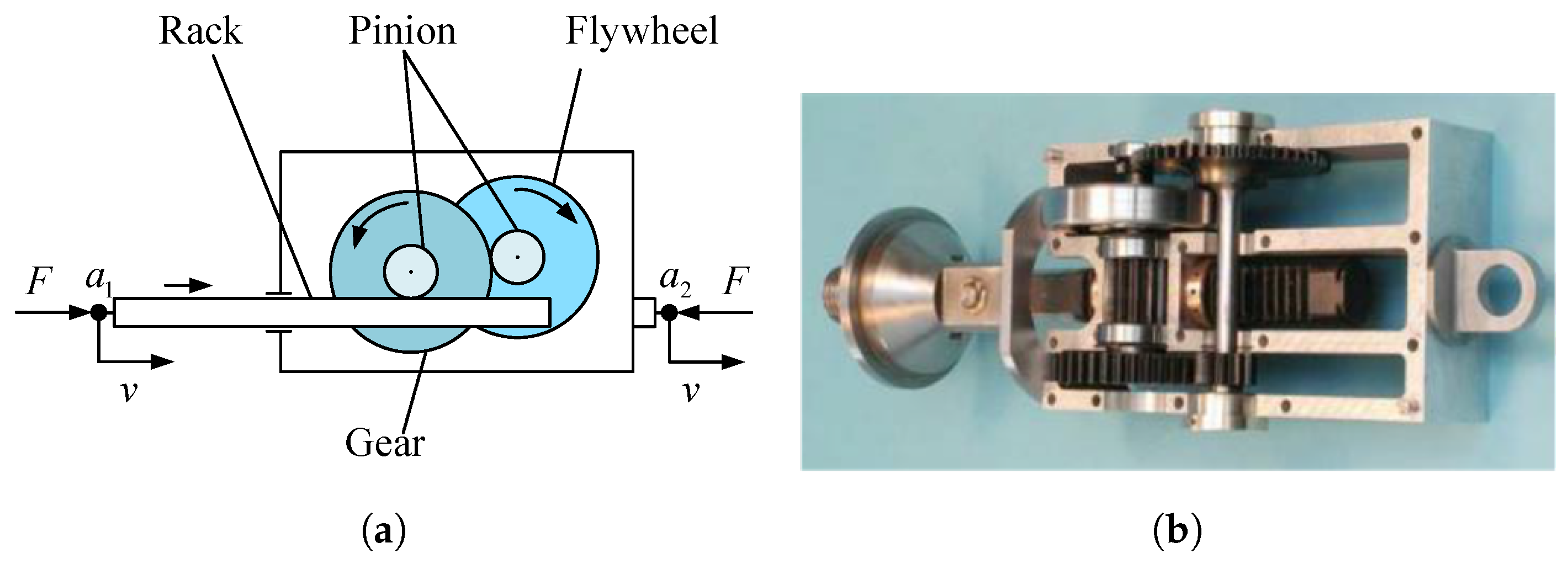
The rack-and-pinion inerter is a type of inerter that uses a rack-and-pinion kinematic pair as its transmission mechanism, as shown in Figure 3. When equal and opposite forces F act on the two terminals of the rack, terminal a 2 generates displacement relative to terminal a 1 . Through the meshing transmission between the rack and left pinion, and between the gear and right pinion, the relative movement between the wheel and vehicle body is converted into rotational motion, and the inertial effect of the flywheel is utilized to realize the inerter function.
The inertance is as follows.
b 1 = I 1 r r 1 r 2 2
where r 1 and r 2 are the radius of the pitch circle of the left and right pinion, respectively. r is the radius of the pitch circle of the gear, and I 1 is the moment of inertia of the flywheel.
Papageorgiou et al. conducted bench test research on the rack-and-pinion inerter, proving its feasibility. They pointed out that the meshing clearance and friction between gears and racks directly affect the mechanical performance of rack-and-pinion inerters. They found that the friction characteristics of rack-and-pinion inerters exhibit triangular waveforms at low frequencies [13,14]. Jiang et al. established a three-dimensional solid model of the rack-and-pinion inerter using Pro/E software, imported the model into ADAMS software, and created a quarter suspension virtual prototype model for simulation analysis. The results showed that the rack-and-pinion inerter has the performance characteristic of passing high frequencies and blocking low frequencies [15]. Fang et al. replaced the flywheel of the rack-and-pinion inerter with an eccentric flywheel that provides excitation force. Simulations under sinusoidal and random excitation conditions demonstrated that the improved rack-and-pinion inerter broadens the amplitude–frequency curve of the system in the resonance region and significantly reduces the resonance peak, thereby achieving better vibration-damping effects [16].

2.2.2. Ball-Screw Inerter

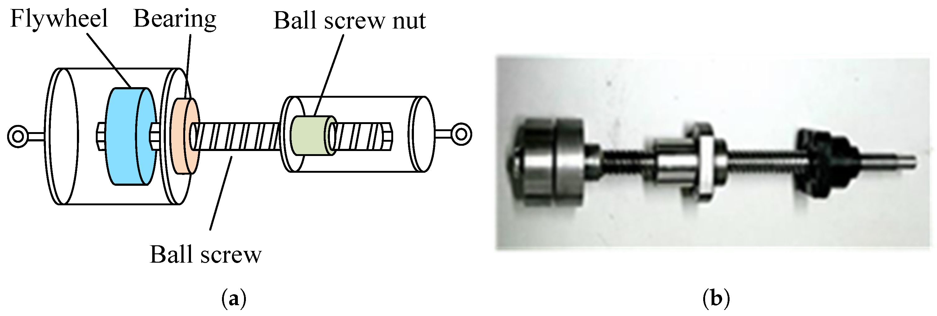
The ball-screw inerter is a type of inerter that uses a ball-screw kinematic pair as its transmission mechanism, as shown in Figure 4. When equal and opposite axial forces are applied to both ends of the inerter, a relative linear displacement occurs between the two ends, which is converted into rotational motion. Then, the screw drives the flywheel to rotate, thereby amplifying the flywheel’s rotational inertia, which achieves encapsulating the inertia of the flywheel.
The inertance is as follows.
b 2 = I 2 2 π P 2
where P is the pitch of the ball screw, and I 2 is the moment of inertia of the flywheel.
Papageorgiou et al. conducted bench tests on the ball-screw inerter, proving its feasibility. They pointed out that clearance and friction have direct impacts on the mechanical performance of ball-screw inerters and found that the friction characteristics of the ball-screw inerter exhibits square waveforms at low frequencies [13,14]. Sun et al. performed bench tests on ball-screw inerters under 51 conditions and discovered that nonlinear elastic forces also contribute to the nonlinear factors of inerters. By using a backpropagation neural network [18,19,20,21,22] to train and predict with 1020 sets of data, the mapping relationship between the output force of the inerter and its main influencing factors can be accurately represented [23]. Zhang et al. investigated the influence of friction on ball-screw inerters by adopting a double-nut spacer preloading for the ball-screw pair, which eliminates backlash with a substantial preload force. Simulation analysis revealed that at low frequencies, where inertial forces are relatively small, friction remains constant and dominates, causing phase drops and amplitude increases in the inerter. As frequency rises, the impact of friction on the inerter decreases, and similarly, the impact of friction diminishes with increasing inertance [24]. Wen et al. studied the influence of the flywheel’s moment of inertia on the inertance in ball-screw inerters. Through experiments, they found that the inertance is related to the flywheel’s moment of inertia—the larger the moment of inertia, the greater the inertance [25]. Guo et al. developed a method to calculate the inertance of ball-screw inerters, taking into account friction. The accuracy of the inertance was verified through experiments. At the same frequency, a smaller lead, nominal radius, and contact angle, along with a larger ball radius and fewer balls, increase the inertance. With consistent geometry, the influence of frequency on the frictional inertance diminishes as frequency increases [26]. Li et al. studied the dynamic breakdown characteristics of inerters. They proposed a novel ball-screw inerter with mechanical diodes, which can reduce adverse effects when a dynamic breakdown occurs in the inerter [27]. Meanwhile, they discovered through bench tests that the inertance of the ball-screw inerter is easily affected by installation preload. Excessive preload causes the measured inertance to be larger than theoretical values, while insufficient preload makes it smaller. Only with appropriate preload does the inerter’s inertance approach the theoretical value. Therefore, they established a virtual-physical mapping model of the inerter and its corresponding experimental system to monitor whether the inerter operates at the ideal inertance state [28].
Ge et al. utilized the compound motion characteristics of planetary gears to propose a planetary flywheel ball-screw inerter and conducted experiments. Compared with a single flywheel, the planetary flywheel significantly increases the ratio of inertance to flywheel mass, and the planetary flywheel can adjust multiple structural parameters to increase this ratio further. However, since the planetary flywheel assembly has greater thickness than a single flywheel under the exact radial dimensions, this inerter is suitable for applications that are sensitive to weight but have relatively sufficient axial space [29]. Yang et al. designed a nylon flywheel with four slotted sliders and cylindrical holes distributed symmetrically at 90 degrees. Compared with passive suspension, the ISD suspension provided better performance [30]. Goh et al. developed a ball-screw inerter featuring a flywheel with four slotted sliders. Each slot contains a slider and a spring, with the slider spring-mounted inside the flywheel. Centrifugal force drives the slider displacement, allowing the inertance to be dynamically adjusted. The results showed that this device outperforms passive inerters, with significant improvements in suspension performance for heavy vehicles compared to passenger cars [31].

2.2.3. Ball-Screw Mechatronic Inerter

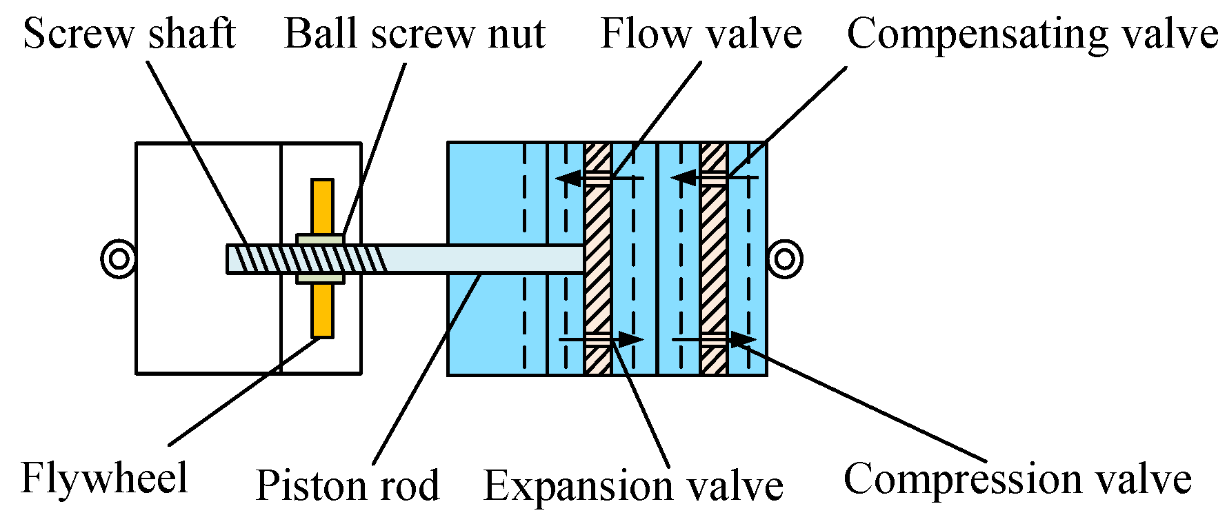
The ball-screw mechatronic inerter is composed of a ball-screw inerter coupled with a rotary motor, as shown in Figure 5. Unlike a ball-screw inerter, the ball screw not only drives the flywheel to rotate, but also drives the motor connected to the ball screw to rotate. At this time, the rotary motor operates in generator mode, converting kinetic energy into electrical energy for storage or dissipation. When a control current is applied to the rotary motor, it operates in motor mode, allowing the inerter to act as an active control force to suppress suspension vibrations.
Wang et al. proposed a ball-screw mechatronic inerter. By combining the ball-screw inerter with a motor, they achieved a composite network of mechanical inertia, damping, and external circuit impedance. Theoretical models suggest that the admittance of this system can be equivalently represented as a higher-order passive mechanical network through mechatronic coupling, thereby significantly reducing the traditional mechanical network’s reliance on multiple physical components and optimizing volume and weight [32]. Yang et al. addressed the issue of fluctuations in mechanical performance output caused by the instant reversal of the ball-screw inerter, due to flywheel inertia, as well as impacts on the screw and nut. They installed two flywheels inside the left cylinder, each connected to the screw via unidirectional clutches mounted in opposite orientations. Regardless of the screw’s rotation direction, only one flywheel will rotate with the screw. Through a coupling device, the screw and motor rotor rotate synchronously, enabling motor control over the screw’s rotational state [33].

2.2.4. Hydraulic Motor Inerter

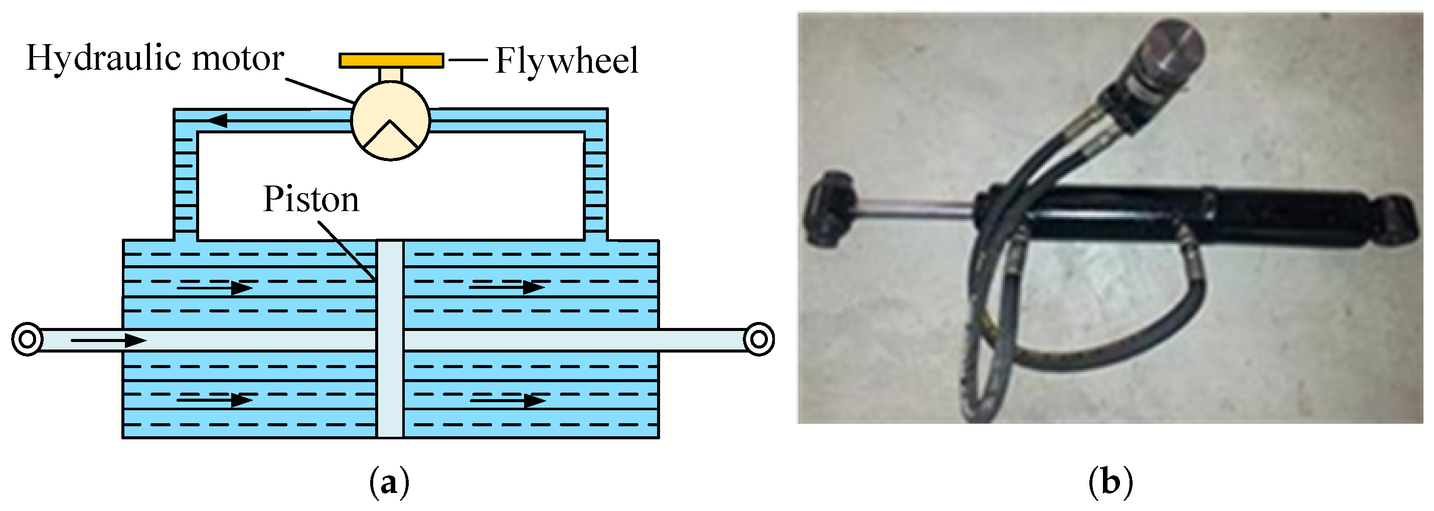
The hydraulic motor inerter consists of a closed hydraulic system comprising a hydraulic cylinder, hydraulic motor, flywheel, and pipelines. The double-piston-rod double-acting hydraulic cylinder ensures equal effective working areas for the oil in both upper and lower chambers of the hydraulic inerter, as shown in Figure 6. When a rightward thrust force F is applied at the left terminal, it causes relative displacement between the two terminals, pushing the hydraulic oil to move to the right. This causes the pressure on the left side of the piston to decrease while the pressure on the right side increases, creating a pressure difference between the upper and lower chambers of the hydraulic cylinder. This pressure difference drives the hydraulic motor to rotate, thereby causing the flywheel to spin and achieving encapsulation of the flywheel’s inertia.
The inertance is as follows.
b 3 = A 2 I 3 η v D 2 η m
where A is the cross-sectional area of the piston, D is the ratio of hydraulic pump flow rate to angular velocity, I 3 is the moment of inertia of the flywheel, η v is the volumetric efficiency of the pump, and η m is the mechanical efficiency of the pump.
Wang et al. proposed a hydraulic motor inerter. This structure can achieve the characteristics of an inerter. The hydraulic cylinder can not only withstand high pressure but also solve the backlash and breakdown problems of mechanical inerters. Considering factors such as damping, compression, and friction, they developed a nonlinear model and verified the effectiveness of the hydraulic motor inerter through prototype testing [34]. Chen et al. established a nonlinear model of the hydraulic motor inerter. The authors analyzed the influence of the flywheel’s moment of inertia, motor displacement, effective working area of the oil, and equivalent length of the return pipeline on the mechanical performance of the inerter. At low frequencies, the output force of the hydraulic motor inerter is primarily a friction force. As the frequency increases, the influence of friction on the output force of the hydraulic inerter diminishes, with inertial force becoming dominant [35]. Chen established a nonlinear model that considers friction and flow pressure losses in hydraulic motor inerters, verifying the model’s accuracy through bench tests. They analyzed how parameters, including oil viscosity, hydraulic pipeline specifications, hydraulic motor displacement, flywheel moment of inertia, and piston rod diameter, affect the external characteristics of hydraulic motor inerters. Simulation results showed that as oil viscosity increases, the inerter’s output force slightly decreases; when considering pipeline damping effects, the output force becomes greater and more stable; after pipeline inner diameter reaches a critical value, maximum force differences decrease significantly; increasing pipeline length noticeably enhances output force; excessive hydraulic motor displacement significantly reduces the inertance; and as flywheel moment of inertia increases, the inertance rises while friction and damping effects weaken [36,37].
Sonng et al. improved the hydraulic motor inerter by adding a circuit between the hydraulic motor and hydraulic cylinder, and incorporating a proportional valve in both this circuit and the hydraulic motor circuit to control the hydraulic system’s flow rate and alter the inerter’s inertance [38]. Bu et al. integrated a proportional valve and four hydraulic check valves into the hydraulic motor inerter. The four check valves form a hydraulic check bridge, while the proportional valve is parallel to the hydraulic motor. This solution addresses issues such as speed fluctuations, impacts, and hysteresis caused by flywheel direction changes, while also enabling adjustment of the hydraulic motor’s flow rate to modify the inerter’s inertance, thereby creating an adjustable hydraulic motor inerter [39]. Yu et al. incorporated a magnetorheological fluid valve into the hydraulic motor inerter. Using MR fluid as the working medium, they regulated fluid viscosity through electromagnetic fields to control valve opening and closing, as well as flow rate, thereby adjusting the inertance [40].

2.2.5. Hydraulic Piston Inerter

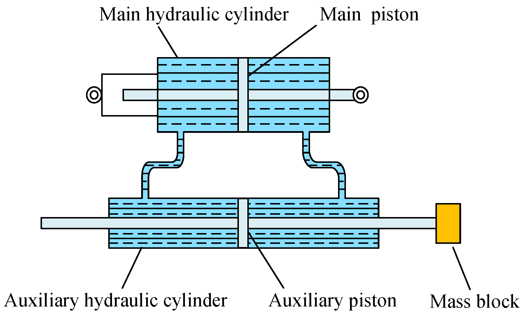
The hydraulic piston inerter mainly consists of two hydraulic cylinders with different cross-sectional areas: a main hydraulic cylinder and an auxiliary hydraulic cylinder, connected by a pipeline. The connecting pipeline is a slender hose, and one terminal of the auxiliary hydraulic cylinder piston is welded and fixed to a mass block, as shown in Figure 7. When relative motion occurs between the upper and lower lugs, the main hydraulic cylinder piston moves accordingly. The lower chamber of the main hydraulic cylinder is connected to the lower chamber of the auxiliary hydraulic cylinder. Under pressure difference, the hydraulic oil moves into the auxiliary cylinder, causing the mass block to move up and down, thereby achieving the inerter function [41].
The inertance is as follows.
b 4 = m A 1 A 2 2
where m is the mass of the weight block, A 1 is the cross-sectional area of the large piston, and A 2 is the cross-sectional area of the small piston.

2.2.6. Hydraulic Electric Inerter

The hydraulic electric inerter combines a hydraulic piston inerter with a linear motor, as shown in Figure 8. The main cylinder barrel and central piston rod serve as the two terminals of the hydraulic electric inerter. The linear motor mover shaft and auxiliary cylinder piston rod are integrated in design, utilizing the cross-section ratio between the primary and auxiliary cylinders to create a force amplification effect, while coupling with the mover shaft mass to form the inerter. When relative motion occurs between the upper lug and lower lug, the lower lug and central piston rod push the main hydraulic cylinder piston to move upward or downward. The lower chamber of the main hydraulic cylinder communicates with the lower chamber of the auxiliary hydraulic cylinder. Since the working chambers of both primary and auxiliary hydraulic cylinders are filled with hydraulic oil, the oil flows into the auxiliary hydraulic cylinder to push its piston upward or downward, thereby driving the mover shaft to move vertically through the auxiliary piston rod. The mover yoke and mover poles on the mover shaft generate relative motion with the stator windings in the motor working chamber. Through force-coupled input via the motor, control over the inerter’s output force can be achieved.
Shen et al. proposed two types of hydraulic electric inerters, and the results of the bench test showed a certain deviation between the theoretical and actual values. The influencing factors were not only frictional force, elastic effect, and nonlinear damping force, but also coil resistance and coil inductance [42]. Zhang et al. developed a vehicle ISD suspension using a hydraulic electric inerter and considered the effects of coil inductance and resistance on the ISD suspension. The study analyzed suspension performance indices under three conditions: without coil inductance, with coil resistance, and with both coil inductance and resistance [43].

2.2.7. Fluid Inerter

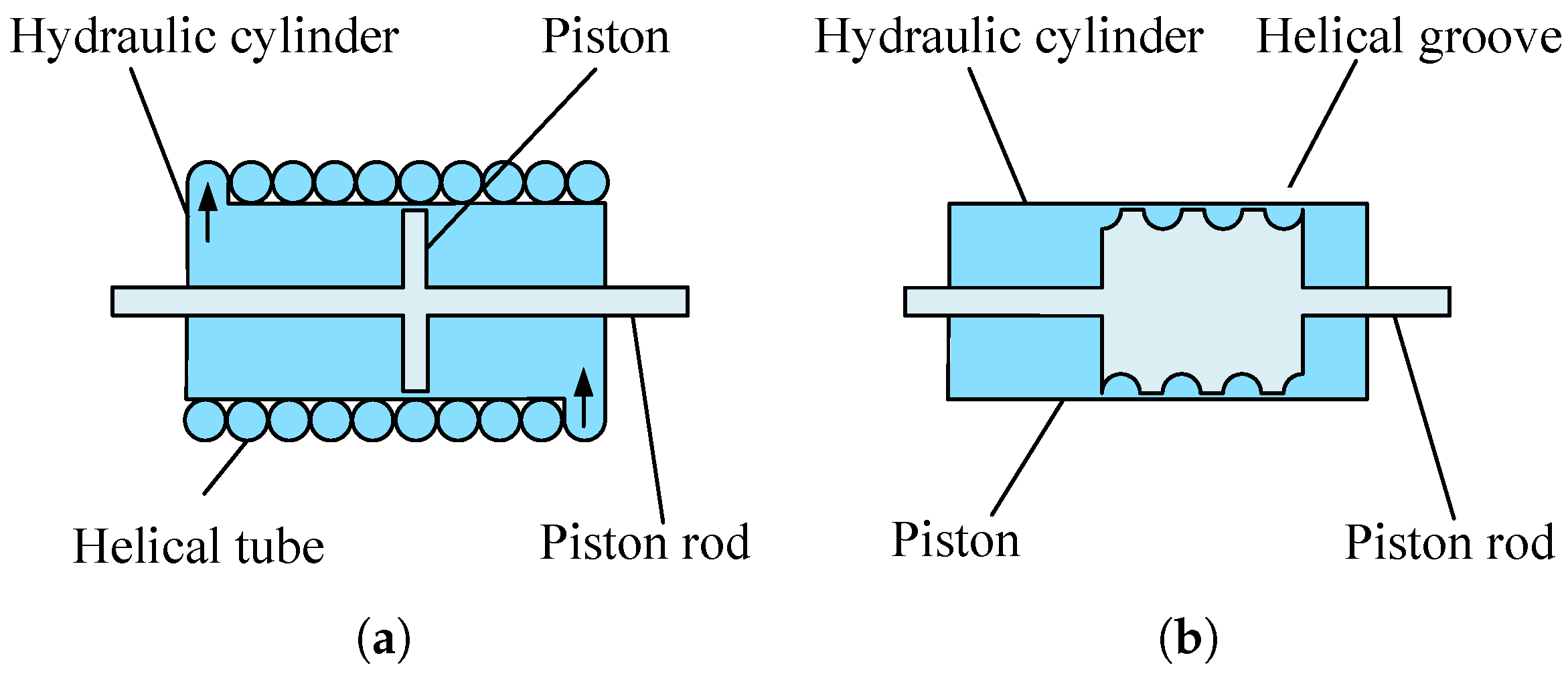
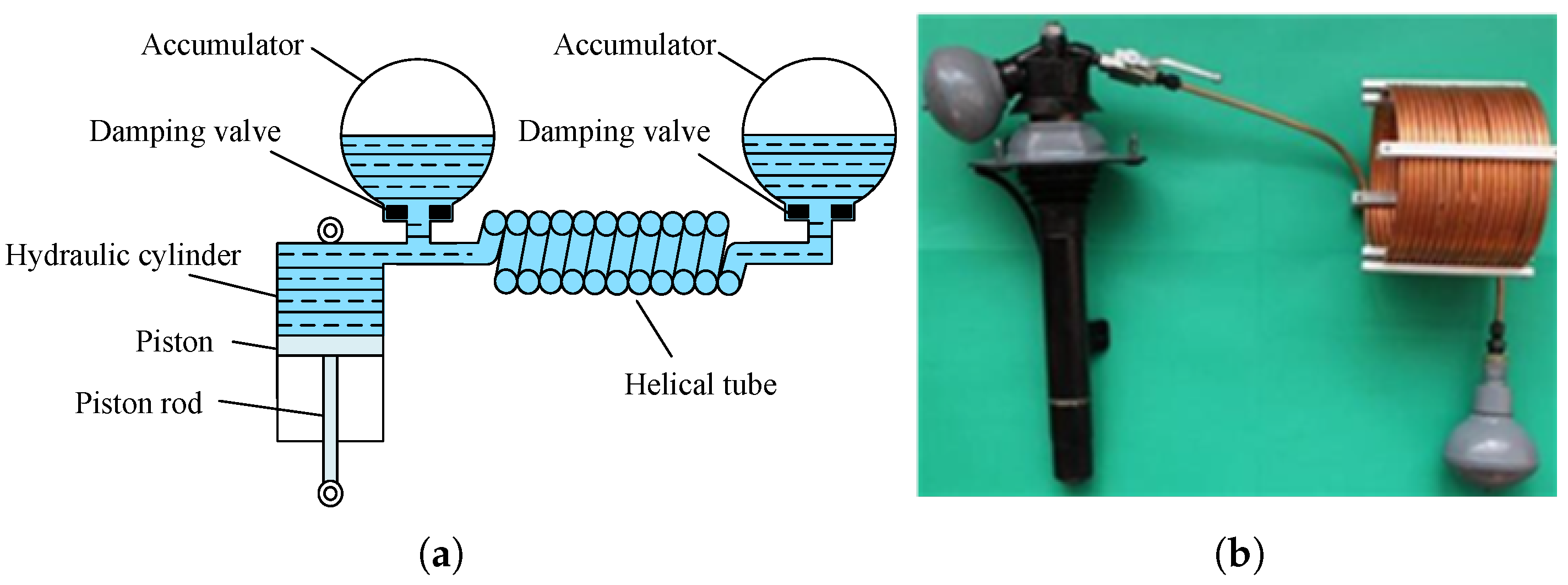
The inner cylindrical surface of the hydraulic cylinder is fitted with the piston and is divided into two chambers. When the piston moves within the hydraulic cylinder, the pressurized oil flows into the helical pipe, creating a liquid flywheel effect. As shown in Figure 9, there are an external helical tube and an internal helical tube fluid inerter.
In the external helical tube fluid inerter, the helical tube is wound around the outer surface of the hydraulic cylinder, with the inlet and outlet of the hydraulic cylinder connected to both ends of the helical tube. The piston pushes the hydraulic fluid inside the hydraulic cylinder from one chamber through the helical tube into another chamber. The fluid flow in the helical tube generates inertia. This type of inerter has low manufacturing difficulty, but the external winding of the tube increases the volume of the inerter, requiring more space in the actual vehicle layout.
The principle of the internal helical tube fluid inerter is similar to that of the external helical tube fluid inerter. The difference is that the helical tube in the internal helical fluid inerter is formed by the spiral grooves on the internal piston, which are in close contact with the inner wall of the hydraulic cylinder. High machining precision is required to ensure the seal between the piston and the hydraulic cylinder. The inertance it can provide is related to the piston length. Additionally, a longer piston length is needed to provide the desired inertial characteristics.
The inertance is as follows.
b 5 = ρ l A 3 A p A 3 2
where ρ is the fluid density, l is the length of the helical capillary tube, A 3 is the cross-sectional area of the helical capillary tube, and A p is the effective piston area.
Swift et al. derived the mathematical model for the inertance and damping force of a fluid inerter, analyzing the influence of fluid dynamic parameters, including channel geometry, Reynolds number, and Dean number. The model’s accuracy was experimentally validated [44]. Wang et al. found that at higher excitation frequencies, the fluid inerter can be equivalently represented as a parallel connection of a damper and an inerter through bench testing [45]. Shen et al. developed nonlinear models for fluid inerters, analyzing nonlinear factors and their influence mechanisms on mechanical output. A support vector machine [46,47,48,49,50] was trained using small-sample data, which enhanced predictive accuracy [51]. Wagg et al. introduced a memory inerter and verified the validity and reliability of the model. The results demonstrated that the inerter can effectively capture its hysteresis characteristics and dynamic response [52]. Wang et al. employed Fluent software to establish a numerical model of the internal flow passage in a fluid inerter’s helical tube. The study investigated the effects of fluid medium, inlet velocity, tube inner diameter, coil diameter, and pitch on pressure difference and friction coefficient [53]. Li et al. proposed calculation methods for a fluid inerter and oil-based constant damping. Analysis revealed that the nonlinear hydraulic inerter model should be treated as a parallel combination of a nonlinear inerter and a viscous damper. Bench tests verified the model’s feasibility [54]. Chillemi et al. established a fluid inerter model incorporating Stribeck friction and fluid compressibility. Frequency-domain and time-domain comparisons proved the model’s reliability across a broad frequency range [55]. Liu et al. developed a numerical flow–heat transfer model for a fluid inerter using Fluent software. The research examined the velocity and temperature field distributions within the helical tube, exploring the relationship between the Nusselt number and various parameters, including the Reynolds number, wall relative roughness, inlet temperature, wall temperature, tube inner diameter, coil diameter, and pitch. The study elucidated the variation patterns of Nusselt number in convective heat transfer through helical tubes, providing theoretical foundations for thermodynamic design of helical-tube hydraulic inerters [56].
Du et al. replaced the helical tube with straight pipes to avoid secondary flow phenomena, proposing a dual-cylinder hydraulic inerter. Bench tests confirmed the model’s validity [57]. Li et al. addressed the key challenge in the fluid inerter, where pipeline damping, inertance, and effective stiffness are inherently coupled and difficult to adjust independently. The authors proposed an innovative serpentine layout inter-pipeline design. Prototype testing confirmed the correctness of the theoretical model and demonstrated the prototype’s performance accuracy and stability [58]. Liao et al. proposed a decoupled fluid inerter consisting of two separated hydraulic cylinders, a helical tube, and two pistons. The pressure difference between the helical tube and hydraulic cylinders generates significant inertial forces and energy storage. Model experiments verified the reliability of the theoretical model, demonstrating excellent energy dissipation capability and stability under various loading conditions [59]. Zhang et al. developed a nonlinear fluid inerter with an additional cylindrical chamber. This chamber consists of three interconnected cylindrical zones, with a larger-radius middle chamber and symmetrically arranged end chambers. Piston movement drives fluid flow between chambers, and the helical groove design creates displacement-dependent variations in the flow path, generating piecewise nonlinear inertial and damping forces. The validated model showed better frequency tunability and vibration suppression compared to conventional helical-groove hydraulic inerters [60].

2.2.8. Hydraulic Controllable Inerter

To achieve adjustable inerter parameters and modify the inertance, Yang et al. designed a hydraulic controllable inerter based on the principles of fluid inertia [61]. As shown in Figure 10, the hydraulic controllable inertor alters its inertance by switching the pipeline connections through solenoid valves. When the straight pipeline is closed and the helical pipeline is open, the system exhibits a larger inertance. When the straight pipeline is open and the helical pipeline is closed, the system demonstrates a smaller inertance. The inertial force is output through two freely movable ends.
The inertance is as follows.
b 6 = b on = ρ π R 3 n P h 2 + 2 π R h 2 + 2 l 0 1 + P h 2 π R h 2 R 2 2 R 1 2 R 3 2 2 b off = ρ l s π R 3 2 R 2 2 R 1 2 R 3 2 2
where R 1 , R 2 , R 3 , and R h are the radii of the piston rod, the inner cylinder, and the inner helical tube, respectively. R h , P h , and n are the radius, pitch, and number of turns of the helical tube, respectively. L 0 and L s are the lengths of the connecting tube and the straight tube, respectively.
Liu et al. established three models for the hydraulic controllable inerter: an ideal model, a nonlinear hydraulic controllable inerter model that considers parasitic damping and friction factors, and a nonlinear hydraulic controllable inerter model accounting for fluid–air mixture conditions and parasitic damping and friction factors. Comparative studies were conducted on the mechanical output performance of these models. Experimental results showed that under fluid–air mixture conditions, the calibrated model more accurately reflects actual test results. The presence of a fluid–air mixture negatively impacts suspension system performance, and nonlinear factors are found to affect control effectiveness [62,63].
Tang et al. proposed a hydraulic controllable inerter, as shown in Figure 11. Its structure consists of a main body comprising a cylinder, piston, and buffer block, along with an inertance adjustment device composed of flexible hoses, solenoid valves, and two helical rigid pipes with different diameters. When hydraulic oil flows from one chamber of the cylinder to another through the slender pipe, it generates an inertial effect. By controlling the on/off states of the two solenoid valves to regulate the oil flow path, the inertance of the hydraulic inerter can be adjusted [64,65].
Tran et al. proposed a hydraulic controllable inerter, as shown in Figure 12. The device adjusts the inertia and damping effects by regulating the flow ratio between the helical channel and the bypass channel. When relative motion occurs between the two endpoints of the inerter due to loading, fluid flows between the two chambers of the hydraulic cylinder. During this process, the fluid passing through the helical channel generates an inertial effect, functioning similarly to a fluid flywheel that stores kinetic energy and produces inertial force through fluid motion. Simultaneously, the bypass channel regulates the fluid flow path through a flow control valve, controlling the flow rate through the helical channel and, thereby, adjusting the inertance of the inerter [67].
The inertance is as follows.
b 7 = ρ l H A H Q H Q C A C A H + ρ l B A B 1 Q H Q C A C A B
where Q H and Q C are the flow rates of the helical channel and hydraulic cylinder, respectively. A H , A C , and A B are the cross-sectional area of the helical channel, hydraulic cylinder, and bypass channel, respectively. l H and l B are the lengths of the helical channel and bypass channel, respectively.

2.2.9. Memory Inerter

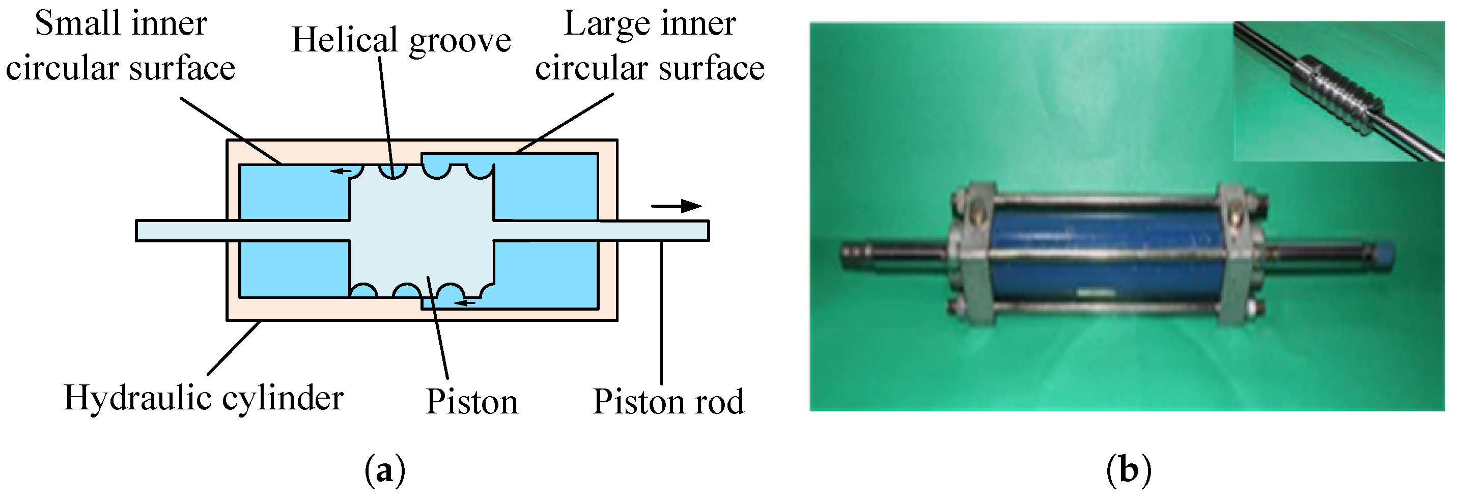
The memory inerter is as shown in Figure 13, which includes a hydraulic cylinder and a piston with helical grooves. The piston fits with the small inner cylindrical surface, dividing the hydraulic cylinder into left and right chambers. The piston is machined with semi-circular cross-section helical grooves, allowing fluid to flow back and forth between the left and right chambers through these grooves. When the piston moves, the length of the helical groove changes continuously in proportion to the piston displacement. Consequently, the mass of fluid in the helical groove also increases or decreases continuously, enabling continuous variation of the inertance. Therefore, the hydraulic memory inerter device is an inertial device whose inertance is related to the piston displacement.
The inertance is as follows.
b 8 x = π ρ d 1 2 d 2 2 2 p h 2 + π d 1 2 p h r h w 2 x
where d 1 and d 2 are the diameters of the piston and the piston rod, respectively. r h is the radius of the helical channel. p h is the pitch of the helical groove. x is the relative displacement between the piston and the cylinder. w is the width of the piston.
Zhang et al. established a nonlinear model of the memory inerter, incorporating dry friction damping, viscous damping, and memory inerter characteristics. The model results are basically consistent with the experimental results. Analysis revealed that the device’s model should consist of a parallel combination of a memory inerter, a viscous damper, and a dry friction damper [68,69].
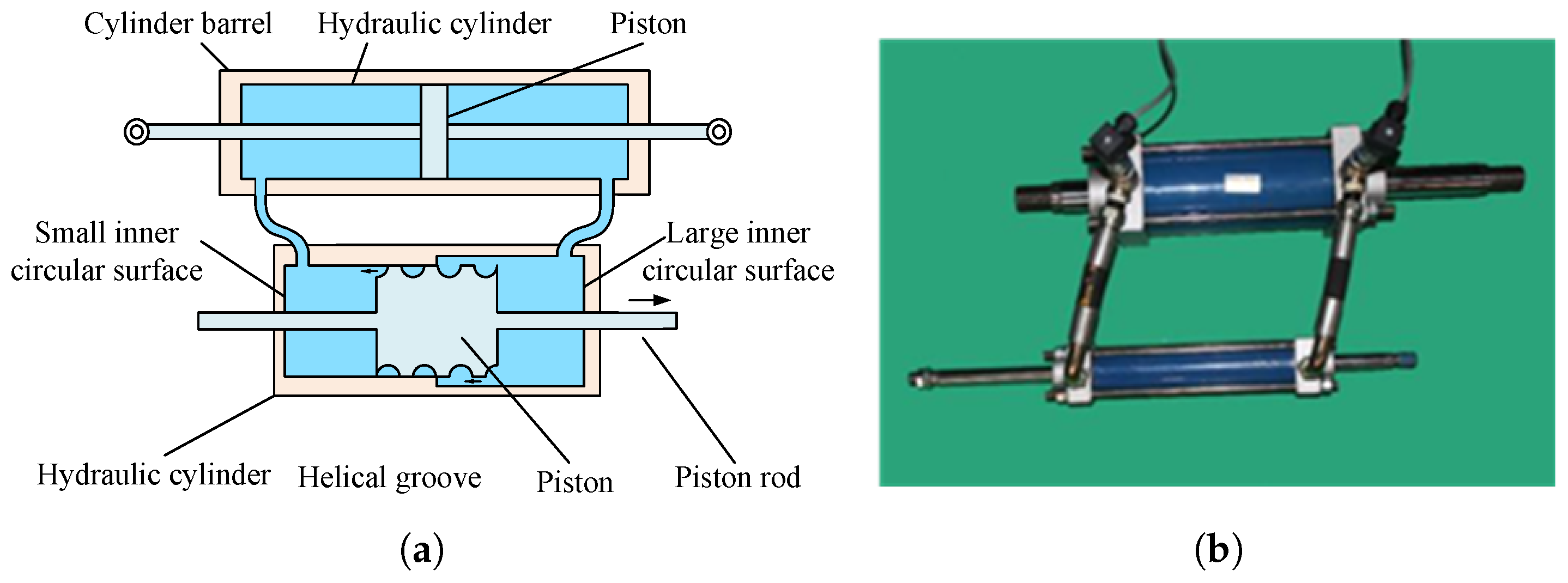
Zhang et al. proposed a hydraulic controllable inerter, consisting of a hydraulic cylinder and an inertance adjustment valve, as shown in Figure 14. The valve body features two inner cylindrical surfaces with different diameters: a large inner cylindrical surface and a small inner cylindrical surface. The outer surface of the valve core mates with the small inner cylindrical surface of the valve body, dividing the valve body into left and right chambers. The outer surface of the valve core is equipped with a helical channel that connects these two chambers. Both ends of the cylinder barrel and valve body are equipped with adjustment valves that control fluid flow, allowing for the regulation of the inertance. The inertance is varied by adjusting the valve core movement to change the length of the helical channel [70,71].
The inertance is as follows.
b 9 x = π ρ D 1 2 D 2 2 2 p h 2 + π d 1 8 p h r h x
where D 1 and D 2 are the diameters of the hydraulic cylinder piston and the piston rod.
In summary, this section reviews the structural types and main characteristics of various inerters, with the specific features listed in Table 1.

2.3. Nonlinear Characteristics of Inerter

Backlash exists in gear pairs and ball-screw transmissions, causing hysteresis and impact phenomena during high-speed rotational reversals of the inerter. For ball-screw-type inerters, installing two flywheels—each connected to the screw via a one-way clutch in opposite orientations—can prevent impact during flywheel reversal. Applying appropriate preload during assembly can also reduce the influence of backlash on the inerter. Hydraulic motor-type inerters can incorporate check valves to mitigate speed fluctuations, impact, and hysteresis caused by flywheel reversal. During operation, gear pairs undergo elastic deformation under load, while friction arises from meshing between gears and racks. The screw undergoes elastic deformation under axial forces and driving torque, accompanied by friction at the contact surfaces. Backlash, elastic effects, and friction all influence the mechanical behavior of the inerter.
Hydraulic inerters exhibit nonlinearity due to hysteresis friction between the liquid and pipe walls under varying pressures and flow velocities, parasitic damping in hydraulic pumps or pistons, and elastic effects resulting from fluid compressibility. During operation, fluid viscosity introduces parasitic damping as the liquid flows through helical and straight pipes. Viscous friction occurs between the fluid and the cylinder and helical pipe walls, while pressure losses arise at the pipe inlets and outlets. Additionally, piston friction, damping forces, and secondary flow phenomena induced by centrifugal forces in curved pipes all affect the mechanical performance of hydraulic inerters.

2.4. Breakdown Phenomenon

When an inerter is subjected to excessive load, its stroke reaches the design limit, resulting in functional failure. In this state, the inerter can no longer operate as intended, effectively causing a short-circuit condition. This leads to a sharp degradation in system performance, rendering the inerter nearly rigid and eliminating its vibration-damping effect, as shown in Figure 15.
To effectively prevent the breakdown phenomenon caused by overloading in inerters, a spring can be placed in parallel with the inerter to distribute the vehicle’s weight, thereby reducing the load on the inerter. An alternative approach is to increase the stroke of the inerter, thereby enhancing its capacity to withstand larger loads. In addition, implementing control strategies can effectively prevent excessive compression or extension of the inerter during operation, further improving its safety. The breakdown phenomenon is commonly observed in mechanical inerters. In contrast, fluid inerters can avoid this failure mode due to their fluid-based characteristics, offering advantages such as higher loading capacity and simpler structural design.

3. ISD Suspension Structural Design

To date, ISD suspension structural design methods can be classified into three categories: analytical methods, synthesis methods, and structure-impedance methods.
The analytical method is applied when the topological structure of the suspension system has been determined. It involves dynamic modelling, parameter optimisation, and time-frequency domain simulations of the predefined structure. This method typically employs structural enumeration and performance screening before conducting analysis. The advantage of the analytical method lies in its ability to rapidly investigate the impedance characteristics and suspension performance within a predetermined structural framework, thereby effectively limiting design complexity. When the number of components is small, the analytical method can quickly and accurately derive the mathematical model of the suspension system. However, as the number of components increases, the computational load of the analytical method grows significantly, leading to substantially higher time and effort requirements.
The synthesis method transforms the study of the entire suspension system into an excitation-network-response problem for analysis. Based on the functional relationship between the excitation (road input) and response (suspension performance output), the transfer function (impedance) of the network (suspension system) is determined. The dynamic expressions of the three fundamental elements (inerter, spring, and damper) are then used to construct the complete transfer function. This approach derives the interconnection among the inerter, spring, and damper, yielding a specific suspension structure and enabling the reverse design of a topological configuration that meets the desired suspension performance. Compared to the analytical method, the synthesis method offers the advantage of representing the suspension system’s topology through impedance, effectively generalizing multiple suspension topologies with a single representative structure. While transfer functions of the same order can be categorized, the actual order coefficients are closely tied to component placement, making it difficult to guarantee that a given structure will achieve optimal performance. Moreover, the component parameters obtained using the synthesis method may not be suitable for practical engineering implementation, leading to increased production costs [73].
The structure-impedance synthesis method [74] combines the structural method and the impedance method. For configurations with a predetermined number of components, it generates generalized structures that encompass all possible combinations through series-parallel arrangements and the elimination of redundant elements. These structures are then comprehensively represented using impedance transfer functions. The structure-impedance synthesis method can effectively control the complexity of the network structure and the component parameter values. However, it is difficult to generalize the impedance transfer function expression for a system with multiple components, and the workload accordingly increases.

3.1. ISD Suspension Structural Design Based on Analytical Method

The design approach for ISD suspension configurations based on analytical methods can be summarized into the following five methodologies [75].
  • Utilizing the concept of cascaded filtering in electrical networks, while preventing breakdown phenomena, is used to design a two-stage series ISD suspension system;
  • Deriving the simplest ISD suspension configuration through combinatorial arrangements of three fundamental elements (spring, damper, and inerter), then proceeding with ISD suspension structural design;
  • Determining optimal connection methods between any two of the three elements by analyzing their series/parallel characteristics, then developing ISD suspension structures accordingly;
  • Replacing the mass element in the traditional DVA with the two-terminal characteristics of the inerter to create vibration absorption subsystems, then coupling the passive DVA with the vehicle’s primary suspension system to obtain high-performance ISD suspension structures;
  • Employing anti-resonance phenomena in inerter-spring-mass systems to address the requirement in ideal skyhook damping/groundhook damping systems where dampers must connect to inertial reference frames, thereby achieving passive implementation of ideal SH systems and resulting in high-performance ISD suspension structures.

3.1.1. The First Type of Analytical Method

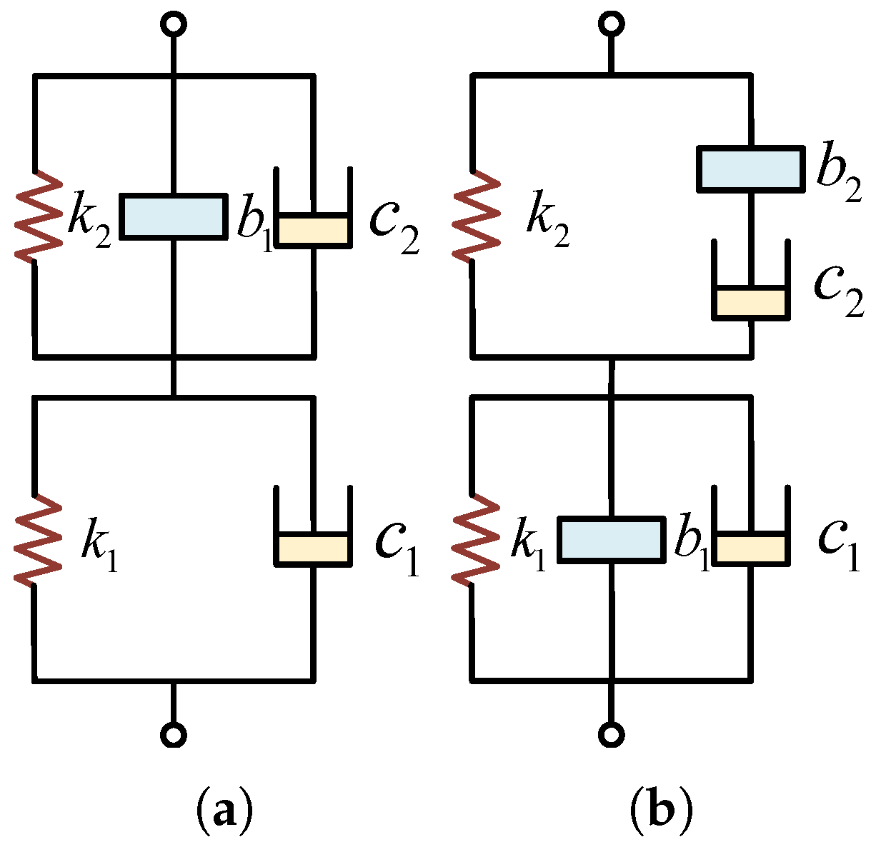
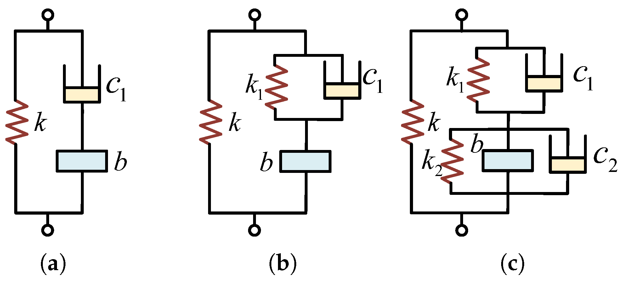
The concept of cascade filtering from electrical engineering was referenced in the references, and a two-stage series ISD suspension network was constructed using a parallel configuration of springs and inerters to prevent breakdown phenomena, as shown in Figure 16a. The first stage blocks high-frequency vibrations, and the second stage blocks low-frequency vibrations. Through bench tests, the improved ISD suspension effectively suppressed low-frequency vertical and pitching vibrations [76,77]. Sun et al. performed Pro/E and ADAMS joint modeling of this suspension structure. Through joint simulation using ADAMS and MATLAB, the two-stage block was shown to effectively suppress both high- and low-frequency vibrations, improving ride comfort [78]. Meanwhile, they indicated that the vibration isolation effectiveness of the two-stage series ISD suspension was minimally affected by the nonlinearity of the inerter [79,80]. Li et al. proposed a two-stage suspension structure with springs, dampers, and inerters in each stage, as shown in Figure 16b. The suspension structure’s ability to suppress resonance peaks was verified in the frequency domain [81].

3.1.2. The Second Type of Analytical Method

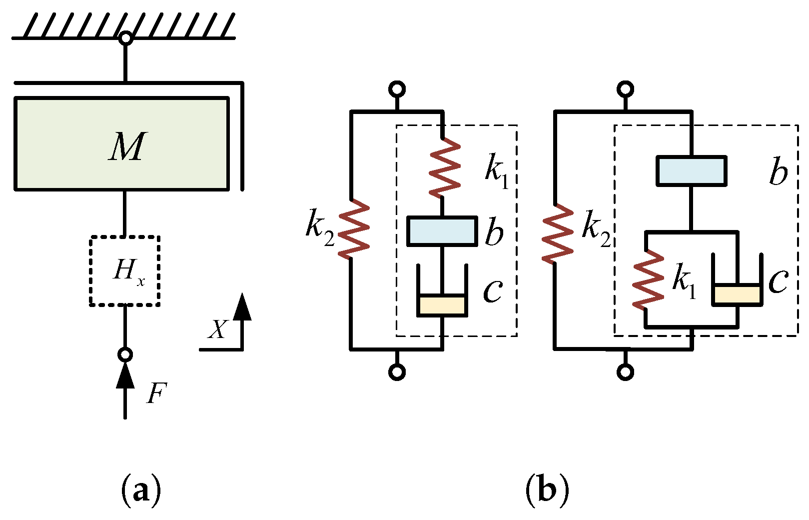
Chen et al. transformed the mechanical model of the vehicle body single-mass system into an equivalent mechanical impedance network diagram to analyze the characteristics of the two-element connection method in vibration transmission and frequency response, as shown in Figure 17a. Through vibration isolation mechanism analysis of the two-element structures, including inerter and damper, inerter and spring, and spring and damper, the ideal connection matching relationships were derived: The inerter and damper should be connected in series, the inerter and spring should be connected in series, and the spring and damper can be connected in series or parallel. Considering the limited space of the vehicle body chassis, two structurally simple ISD suspension designs were proposed, as shown in Figure 17b. The results indicated that the second structure is a more ideal passive ISD suspension structure for the vehicle, which not only effectively improves the vehicle’s ride comfort but also enhances its safety [82].

3.1.3. The Third Type of Analytical Method

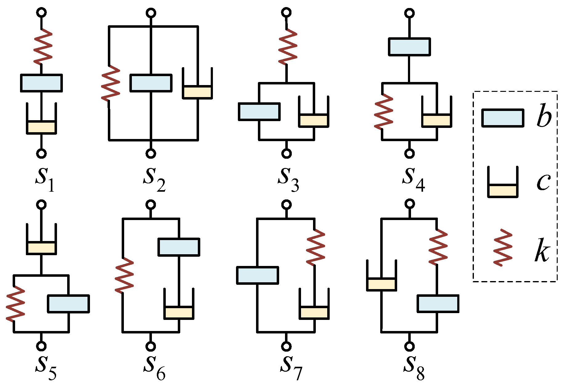
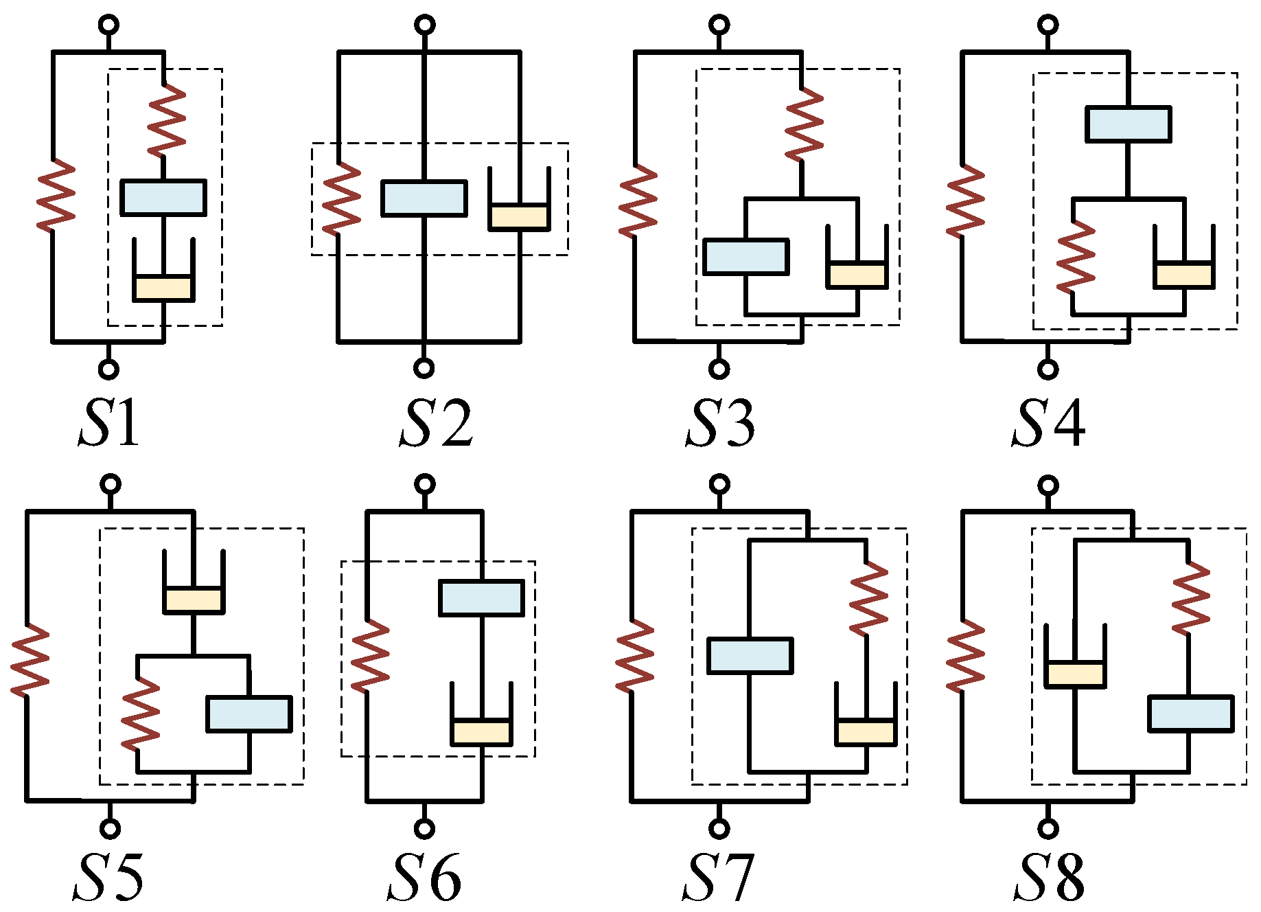
Yang et al. derived eight simple three-element ISD suspension structures by arranging and combining the three elements of the inerter, spring, and damper, as shown in Figure 18. Only structures S 2 and S 6 are parallel to the spring and can be directly used in vehicle suspension systems. Simulation results show that the S 6 structure surpasses the traditional passive suspension in performance indicators, such as body acceleration, suspension dynamic travel, and dynamic tire load [83].
To avoid breakdown phenomena, Chen et al. modified the structures that were not parallel to the spring, and made them all parallel to the spring, as shown in Figure 19. Simulation results indicate that the S 4 and S 6 structures are the best two design options. The S 4 structure can better balance the suspension’s various performance indicators. In contrast, the S 6 structure shows improvements in the suspension dynamic travel and the root mean square (RMS) of dynamic tire load [84]. Yang et al. optimized the parameters of the S 4 structure ISD suspension using a multi-population genetic algorithm [85,86,87,88]. The overall performance of the optimized ISD suspension was significantly improved. The RMS value of the vehicle’s vertical acceleration decreased by 17.6%, the pitch angle decreased by 19.1%, and the roll angle decreased by 25.2%. These improvements effectively enhanced vehicle ride comfort and driving safety [89]. Yang et al. evaluated the performance and understood the basic mechanism of eight suspension systems based on their impedance characteristics [90].
Jiang et al. created all the structures in Figure 18 that were not in parallel with the spring, as well as those arranged in parallel with the spring, resulting in 12 ISD suspension structures. In addition to the eight structures in Figure 19, another set of suspension structures, including S 1 , S 3 , S 4 , and S 5 , were obtained with a different parallel configuration to the spring, as shown in Figure 20. Through the study of these 12 ISD suspension structures, eight structures were found to outperform traditional suspensions in terms of performance. Among them, the S 2 structure performs better in low-frequency vibration reduction. However, the vibration reduction effect in the mid- and high-frequency ranges is inferior to that of traditional suspensions. The body acceleration and dynamic tire load power spectral density of the S 5 and S 12 structures improved in the low-frequency range. However, the suspension dynamic travel worsened to varying degrees, leading to frequent collisions with the limit block and significantly reducing vehicle safety. The vibration reduction effect of the S 1 structure was improved, but the structure is of a higher order and relatively complex. To achieve a simple structure with superior performance, S 6 , featuring fewer components and a lower order, can simultaneously suppress both high- and low-frequency vehicle vibrations. The S 8 structure offers good vibration reduction performance and is easy to implement in engineering, while S 3 and S 4 demonstrate excellent vibration reduction performance, being simple, feasible, and ready for industrialization [91].
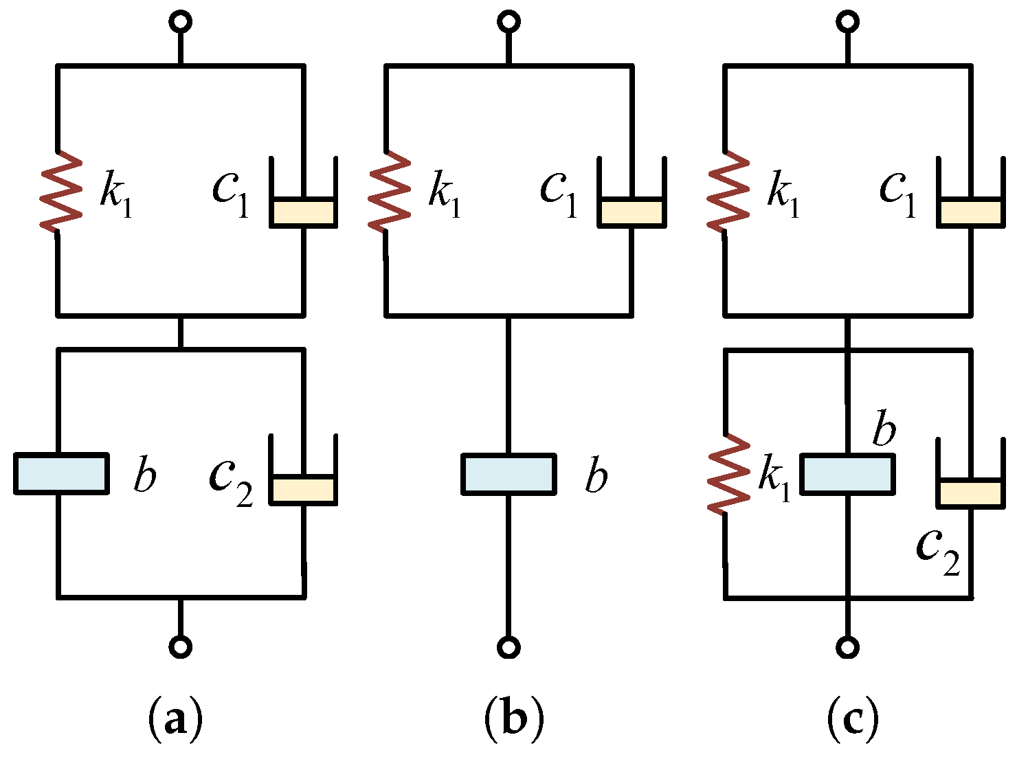
Du et al. first verified, through comparative simulation, that the inerter and spring configuration for vibration isolation should adopt a series arrangement, as shown in Figure 21a. To avoid breakdown phenomena, the inerter and spring were then connected in parallel, as shown in Figure 21b. Three cases were considered: k 1 , k 2 , and k 1 k 2 . Finally, a damping element that rapidly attenuates vibrations is required in the suspension, as shown in Figure 21c. Seven cases were considered: c 1 , c 2 , c 3 , c 1 c 2 , c 1 c 3 , c 2 c 3 , and c 1 c 2 c 3 , resulting in 21 suspension structures in total. Nine representative structures were selected for simulation, and the results indicated that five of these structures exhibit good vibration reduction performance, with simple structural realization and significant potential for engineering applications [92]. Li et al. applied the c 3 c 2 b k 2 suspension structure from Figure 21c in a hybrid vehicle. Compared to traditional suspensions, the ISD suspension effectively attenuated the vibration signals generated when the vehicle drove on uneven roads [93].

3.1.4. The Fourth Type of Analytical Method

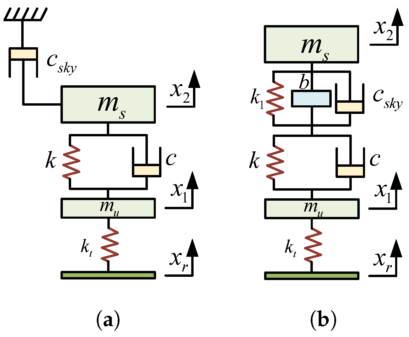
Zhang et al. found that the anti-resonance characteristic of the inerter-spring-mass element system can cause the mass element, initially in a vibrating state, to remain stationary. An ideal passive skyhook damping implementation method was proposed, designing a passive skyhook damping suspension system that requires no energy input and is independent of control systems. A parallel spring and inerter were inserted between the sprung mass and the suspension in Figure 22a, and the skyhook damping was connected in parallel with the inerter, resulting in a passive skyhook damping suspension system, as shown in Figure 22b. The correctness and effectiveness of the ideal passive skyhook damping implementation method were theoretically verified [94,95]. Jiang et al. conducted a reduced-order optimization of the ISD suspension structure, which performed similarly to the passive skyhook damping ISD suspension, with a simpler structure [96].
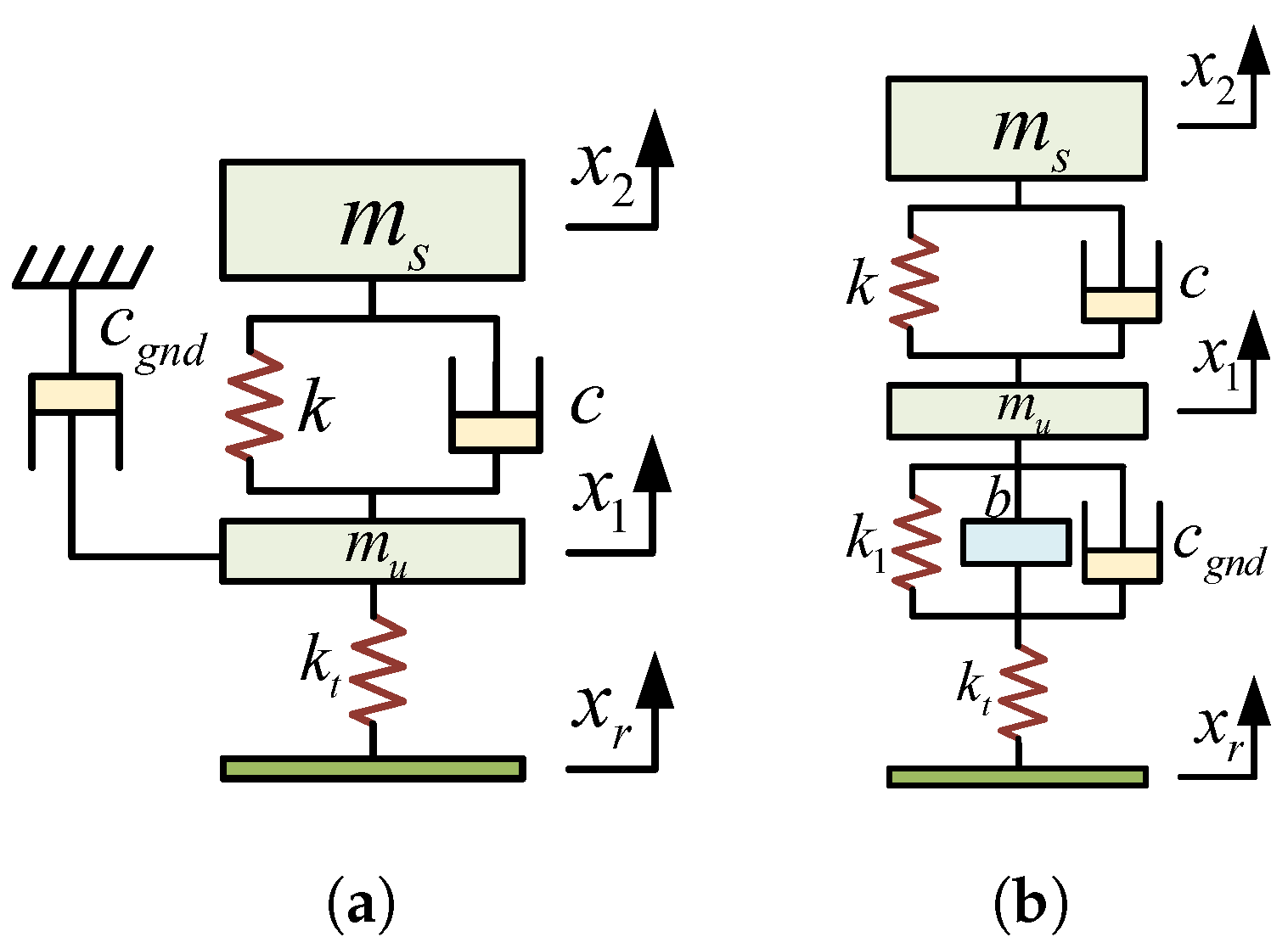
Zhang et al. proposed a passive groundhook damping suspension system design method, as shown in Figure 23a. Similar to the passive skyhook damping implementation method, this method converts the resonance of the unsprung mass into the resonance of the inerter, eliminating the resonance of the unsprung mass. At the same time, the groundhook damping absorbs the vibration energy of the unsprung mass and converts it into absorbed vibration energy of the inerter, as shown in Figure 23b. The correctness and feasibility of the ideal passive groundhook damping implementation method were theoretically verified, effectively suppressing wheel resonance and significantly improving tire–ground contact performance [97]. Meanwhile, they established a complete vehicle Simscape model incorporating the passive groundhook damping ISD suspension. Simulation results showed that the ISD suspension could effectively suppress wheel resonance, with its performance nearly identical to that of the ideal groundhook damping suspension [98]. Nie et al. applied the ideal passive groundhook damping implementation method to the vehicle suspension system, which improved the low-frequency response characteristics and ride comfort and validated the correctness of the method [99].

3.1.5. The Fifth Type of Analytical Method

Yang et al. used the equivalent mechanical impedance network diagram of the passive DVA to incorporate the inerter into the DVA design, establishing an improved DVA model. This improved DVA model structure was introduced into the ISD suspension [100], as shown in Figure 24. Ge et al. developed an active inerter DVA suspension. They proposed a body acceleration compensation control strategy to enhance the performance of the inerter DVA suspension, thereby approaching the ideal DVA. This effectively broadens the vibration attenuation frequency range, improving ride comfort [101].
Through the above analysis, whether using the enumeration method or the ISD suspension structure based on DVA theory, the S 4 suspension structure has the best performance. The S 4 suspension structure is simple, featuring a short system state response time, minimal overshoot in the response output, and excellent dynamic performance. The frequency-amplitude characteristics of the performance indicators for this suspension structure vary with changes in component parameters as follows: An increase in the main spring stiffness and damping coefficient causes the suspension’s frequency-amplitude characteristics to change from three resonance peaks to two resonance peaks. An increase in the secondary spring stiffness and inertial mass coefficient causes the suspension’s frequency-amplitude characteristics to change from two resonance peaks to three resonance peaks. The main spring stiffness and damping coefficient have a significant influence on the RMS value of the body acceleration. All four component parameters influence the RMS value of the suspension dynamic travel. The damping coefficient influences the RMS value of the tire dynamic load [102].

3.2. ISD Suspension Structural Design Based on Synthesis Method

3.2.1. The First Type of Synthesis Method

Chen et al. obtained a two-stage spring series ISD suspension using the network synthesis method, as shown in Figure 25. The two-stage ISD suspension improved ride comfort and driving safety at low frequencies [103].
Nie et al. proposed a network synthesis method for memory inerters in suspension systems. Using the impedance synthesis method, first-to-third-order ISD suspension structures were designed, as shown in Figure 26. Compared to a fluid inerter, the memory inerter suspension designed using the network synthesis method can be equivalently represented as a semi-active suspension with adjustable inertance that depends on the initial displacement, offering good load adaptability and enhancing ride comfort under various load conditions [104].
Nie et al. used a network synthesis method to obtain the S 4 structure ISD suspension, which effectively reduced low-frequency vertical vibrations, enhancing ride comfort [105]. Hu et al. designed three passive suspension structures using low-order admittance functions and converted them into mechanical networks through network synthesis, completing the passive design of the suspension system. This was combined with a semi-active damper to construct an ISD semi-active suspension [106]. Chen et al. applied the Foster transformation of passive network synthesis theory to propose a method for reducing the order of high-order impedance transfer functions, and the parameters were optimized using the particle swarm optimization algorithm [107,108,109,110]. This method achieved passive implementation of high-order impedance transfer functions through network synthesis, using a bi-cubic impedance transfer function as the study object and employing only seven components. The approach simulates equivalent mechanical network components using electrical network elements, significantly reducing the structural complexity of mechanical network components [111]. Then, they proposed a realizable synthesis design method for fractional-order (FD) ISD suspension. Using a bi-quadratic transfer function as the research object, the FD component equivalent network structure was designed, which demonstrated superior performance [112]. Li et al. divided the semi-active suspension system into passive and controllable parts. Using network synthesis, the S 4 suspension structure was obtained, and a skyhook damping control strategy was designed, which effectively improved the vehicle’s comfort and stability [113].

3.2.2. The Second Type of Synthesis Method

Yang et al. proposed a bridge network structure to address the issue with the most straightforward implementation of high-order impedance, thereby simulating the target mechanical impedance equivalently. The most common bridge network consists of five resistive elements, and the equivalent network of the bridge network is shown in Figure 27a. The Δ and Y structure replaces the equivalent impedance. Since resistive impedance is the simplest and does not affect the overall impedance order, the remaining two components of the bridge network are resistors, as shown in Figure 27b. Three types of bridge network structures and three types of series-parallel structures were obtained and simulated for comparison, as shown in Figure 28. The study found that, for the same number of components, the impedance order formed by the bridge network is higher than that of the series-parallel network. Moreover, the mechatronic inerter suspension for vehicles based on the bridge network showed better performance than that based on the series-parallel network [114]. Then, they summarized a bridge electrical network composed of two capacitors, two inductors, and one resistor, and analyzed the impedance structures of various configurations. Ultimately, a double-quadratic impedance function can be realized using only four energy storage elements and one energy dissipation element. Compared to the implementation of high-order impedance functions with series-parallel networks, the bridge network requires only five components to achieve this [115].

3.3. ISD Suspension Structural Design Based on Structure-Impedance Method

As shown in Table 2, the structure-impedance method was used to summarize and express these eight structures in Figure 18.
For the S 1 , S 2 , S 3 , and S 4 structures, the expression Y 1 can be used for a comprehensive representation. For the S 5 , S 6 , S 7 , and S 8 structures, the expression Y 2 can be used for a comprehensive representation. These two overall layouts are obtained, as shown in Figure 29. The structure-impedance method effectively controls the complexity of the network structure and the parameter values of the components. However, it is difficult to generalize the impedance transfer function expression for a system with multiple components, and the workload accordingly increases [116].
Y 1 s = b c s 2 + b k 4 + k 6 s + c k 2 + k 6 b c 1 / k 3 s 3 + b s 2 + c s + k 2 + k 4
Y 2 s = b c 1 / k 1 + 1 / k 2 s 3 + b s 2 + c s + k 3 b 1 / k 1 + 1 / k 5 s 3 + c 1 / k 2 + 1 / k 5 s 2 + s

3.4. ISD Suspension Spatial Layout

Currently, research on the spatial layout of vehicle ISD suspension systems primarily focuses on two-stage series ISD suspension structures, which typically employ I-beam, lever, and through-type layouts [117]. Then, the integrated design of the ISD suspension is another approach to solve the problem of mechanical component spatial layout. In mechanical systems, the arrangement of spring components is the most flexible, while the spatial volume of inerter and damping elements is relatively large. In cases with limited layout space, the inerter and damper can be optimized in terms of internal structure and designed as an integrated device. This mainly includes the following arrangements: a coaxial parallel arrangement of the inerter and damper, a coaxial series arrangement of the inerter and damper, and a coaxial parallel arrangement of the inerter, damper, and spring.
Zhang et al. proposed an integrated ISD suspension combining a hydraulic inerter and a hydro-pneumatic spring, as shown in Figure 30. The central air chamber of the hydro-pneumatic spring is connected to the working cylinder of the hydro-pneumatic spring, with a hydro-pneumatic spring damping valve set between them. The stiffness and damping produced by them are in parallel. The hydraulic inerter is made of a metal spiral tube, one end of which is connected to the working cylinder of the hydro-pneumatic spring, and the other end is connected to an additional gas chamber of the hydro-pneumatic spring. It provides a rebound force, causing the oil inside the metal spiral tube to flow back to the working cylinder of the hydro-pneumatic spring. When the hydraulic oil moves reciprocally inside the metal spiral tube, an inertial force is generated, achieving the inertial effect [118].
Zhang et al. applied a hydraulic integrated inerter to the front and rear suspensions of a military off-road vehicle. Compared to traditional suspensions, the ISD suspension effectively suppressed vertical, pitching, and rolling vibrations, significantly improving ride comfort [119]. Nie et al. used the AMEsim software to build a heavy multi-axle vehicle model with a hydraulic integrated inerter, performing simulation analysis and real-world vehicle road tests. Compared to traditional hydraulic suspensions, the ISD suspension effectively suppressed vibrations from both sprung and unsprung masses [120]. Meanwhile, they used the AMEsim software to build a comprehensive vehicle model that incorporates a hydraulic integrated inerter, and performed simulation analysis and bench tests. This successfully implemented a two-stage series ISD suspension, featuring a compact structure that solves layout difficulties in real vehicles, effectively improving vehicle ride comfort and handling [121,122]. Yang et al. added hydraulic control valves to this setup and proposed an integrated semi-active ISD suspension. They adopted model predictive control (MPC), and simulation results showed that the ISD suspension performed better at low frequencies. At the same time, the valve opening was reduced to ensure the service life of the hydraulic control valve [123,124].
Shen et al. proposed a hydraulic piston inerter and damper coaxial series integrated structure, as shown in Figure 31. The working principle of the integrated structure is that the inerter and damper are arranged coaxially in series, with the working chambers of the inerter and damper sharing a standard piston rod, which serves as the symmetry axis. The upper end of the piston rod has a lead screw structure, with the lead screw nut connected to the lead screw thread and limited within the inerter’s working chamber. The flywheel is fixed at the outer end of the lead screw nut, and as the piston rod moves up and down, the flywheel and lead screw nut rotate inside the inerter’s working chamber, thereby achieving the inertial effect. The lower end of the piston rod is in the damper’s working chamber, which is filled with oil. The oil flows repeatedly in the damper’s working chamber through the action of four throttling valves, thereby achieving the damping effect [125].
Lei et al. connected the hydraulic integrated inerter in parallel with an air spring, which significantly improved the vehicle’s vibration isolation performance [126].
With the development of the ball-screw mechatronic inerter and hydraulic electrical inerter, mechanical network structures can be equivalently replaced by electrical networks. This not only enhances system performance but also significantly optimizes the spatial layout constraints of suspension components, making the realization of higher-order, complex structures possible. As a result, it broadens the engineering application prospects of ISD suspensions.

4. ISD Suspension System Control Strategy

Although the ISD suspension structure can improve vehicle suspension performance to some extent, it still struggles to adapt to complex road conditions. Therefore, there is a need to design an ISD suspension control system that can dynamically control the suspension based on the vehicle state and road conditions, achieving optimal overall driving performance. Common control methods include skyhook damping control (SH), groundhook damping control (GH), hybrid-hook damping control (HH), acceleration-driven damping control (ADD), power-driven damping control (PDD), fuzzy control [127,128,129,130,131,132], PID control [133,134,135,136,137,138,139], sliding mode control (SMC) [140,141,142], adaptive control [143,144,145,146,147], MPC [148,149], and active disturbance rejection control (ADRC) [150,151,152], etc.

4.1. Skyhook Control

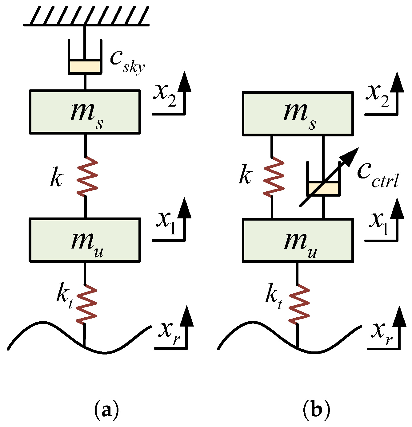
The SH theory [153] is a classic vehicle suspension control method that focused on ride comfort, as shown in Figure 32. The basic principle is to install a damper device with an adjustable damping force between the sprung mass and an imaginary skyhook. The damping coefficient changes according to the direction of the relative velocity between the sprung mass and the suspension, reducing the suspension dynamic travel and achieving the goal of reducing the force between the road surface and the tire.
For the actual generation of skyhook damping force in the suspension, it is typically achieved by adjusting the damping coefficient placed between the sprung and unsprung masses. The expression is as follows.
c ctrl = c max , x ˙ 2 x ˙ 2 x ˙ 1 0 c min , x ˙ 2 x ˙ 2 x ˙ 1 < 0
The SH has significant limitations in the frequency domain. At low frequencies (below 1 Hz), the phase difference between body velocity and suspension velocity is slight, allowing effective suppression of body vibration. However, as the frequency increases (above 10 Hz), the phase difference between the two approaches 90°, causing frequent switching of the damper control. In this frequency range, small damping is required to improve comfort, which conflicts with the control logic and actual needs, weakening the high-frequency control effect. This suggests that traditional SH is effective at low frequencies but has notable limitations in the mid-to-high-frequency range [154].
The researchers have proposed improvement strategies to overcome this limitation. Shen et al. proposed a FD-SH suspension as a reference model and designed an adaptive controller. The output of the reference model guides the actual system response, thereby achieving effective suppression of vehicle vibrations. The results showed that the FD-SH ISD suspension outperforms the SH ISD suspension in both time and frequency domains [155]. Yang et al. proposed a generalized SH strategy for the ISD suspension. Compared to passive suspension, ISD suspension, and SH ISD suspension, it effectively improved the vehicle’s ride comfort and reduced body acceleration [156].

4.2. Groundhook Control

The theory of GH [157] is similar to that of SH, as shown in Figure 33, where an adjustable damper device is installed between the unsprung mass and an imaginary rigid wall to dissipate the energy from wheel vibrations continuously. This is a semi-active control strategy designed to enhance road adhesion, and the GH coefficient also varies according to the relative velocity direction of the unsprung mass.
Similar to the ideal SH strategy, the ideal GH strategy for generating groundhook damping force in the suspension is also achieved by adjusting the damping coefficient placed between the sprung mass and unsprung mass; the expression is as follows.
c ctrl = c max , x ˙ 1 x ˙ 2 x ˙ 1 0 c min , x ˙ 1 x ˙ 2 x ˙ 1 < 0
Li et al. used a second-order GH positive-real network as a reference model and proposed an adaptive control strategy. By adjusting the output force through the motor, the controllable ISD suspension effectively suppresses wheel vibrations over a wider frequency range compared to traditional suspensions [158]. Ping et al. proposed a generalized GH strategy, which reveals the regulation of suspension performance indicators by transfer functions from the first to the fifth order. The results indicated that third-order transfer function control can reduce dynamic tire load by 8% while slightly optimizing the body acceleration [159].
Similarly, GH also has frequency-domain limitations, exhibiting characteristics opposite to those of SH. In the low-frequency range, the relative speed between the wheel and the suspension has little or no phase difference, with the damper in a low damping state. However, to improve road friendliness, a higher damping coefficient is required. Therefore, in the low-frequency range, GH can only reduce the absolute wheel speed but cannot effectively control the relative displacement between the vehicle body and the wheel, limiting improvements in road friendliness. In the frequency range around 10 Hz and above, the phase difference between the vehicle body speed and the suspension movement is approximately 180°, causing the damper to work in a high-damping state, which satisfies road friendliness requirements. This indicates that traditional GH is effective at high frequencies but has significant limitations in the low-frequency range [154].

4.3. Hybrid-Hook Control

A comprehensive analysis of the ideal SH and GH strategies shows that both control implementations target either the sprung mass or the unsprung mass as the controlled object. By applying damping control forces through actual dampers, vibration isolation performance can be enhanced for either the vehicle body or wheel, while simultaneously intensifying the vibration response of the other part. SH primarily aims to improve ride comfort, while GH focuses on enhancing driving safety and road friendliness. HH theory [160,161] introduces a weighting factor that outputs the effects of SH and GH according to the designed ratio, as shown in Figure 34.
The expression is as follows.
F hybrid = α F sky + 1 α F gnd
c ctrl = α c sky x ˙ 2 1 α c gnd x ˙ 1 x ˙ 2 x ˙ 1
The HH strategy blends the benefits of SH and GH. As the damping weighting factor α changes, suspension performance fluctuates accordingly. When α 1 , ride comfort improves, while when α 0 , tire dynamic load evaluation improves. Therefore, selecting an appropriate damping weighting factor α is crucial for balancing ride comfort and road friendliness. The optimal coordination of ride comfort and road friendliness is typically achieved when 0.4 α 0.6 [162].
Zhang et al. compared the performance of semi-active ISD suspensions with SH, GH, and HH. The results showed that the HH ISD suspension performs better when considering both ride comfort and tire grip [163]. Yang et al. studied the phase deviations of SH, GH, and ADD at different frequencies. A generalized HH method was proposed to compensate for phase deviations. It significantly improved the ride comfort and road friendliness [164,165]. Yang et al. proposed a HH ISD suspension as a reference model. MPC was employed to adjust the output force through the motor, which improved the ride comfort and road friendliness of heavy vehicles [166]. Shen et al. used the FD-HH ISD suspension as a reference model and designed an adaptive control to adjust the output force. Through bench testing, the FD ISD suspension demonstrated enhanced vibration damping capabilities [167].

4.4. Acceleration-Driven Damping Control

Similar to SH and GH, the ADD strategy [168] adjusts the damping coefficient based on the direction of the sprung mass acceleration and suspension relative speed. When both are in the same direction, the damping coefficient is at its maximum; when opposite, it is at its minimum. The expression is as follows.
c ctrl = c max , x ¨ 2 x ¨ 2 x ¨ 1 0 c min , x ¨ 2 x ¨ 2 x ¨ 1 < 0
Similar to SH, the ADD strategy is also a switch control that does not require road information. It changes the reference signal from the vehicle body’s velocity to acceleration, making engineering data collection easier. Unlike SH, the ADD strategy suppresses sprung mass acceleration across all frequency bands, except for low frequencies and the inherent frequency near the sprung mass [169].
Yang et al. proposed an ISD suspension model based on an ADD positive-real network, using SMC to adjust the output force. This achieved vibration suppression across a wider frequency range, significantly enhancing suspension comfort and handling [170]. Liu et al. proposed a HH and a SH-ADD ISD suspension. Simulation results indicated that HH control performs excellently in reducing body acceleration and dynamic tire load, while SH-ADD control improves vehicle comfort [171].

4.5. Power-Driven Damping Control

The PDD strategy [172] is a control strategy proposed from an energy perspective to enhance vehicle ride comfort. When the power absorbed by the spring and damper from the sprung mass is less than the power released to the unsprung mass, the damping coefficient is at its maximum. When it exceeds or equals the released power, it is at its minimum. When the relative velocity is zero and the displacement is non-zero, the damping coefficient is the average of the maximum and minimum values. Otherwise, it is the inverse of the ratio of the spring’s force to the suspension’s velocity. The expression is as follows.
c ctrl = c max , k x 2 x 1 x ˙ 2 x ˙ 1 + c max x ˙ 2 x ˙ 1 2 < 0 c min , k x 2 x 1 x ˙ 2 x ˙ 1 + c max x ˙ 2 x ˙ 1 2 0 c max + c min 2 , x ˙ 2 x ˙ 1 = 0   &   x 2 x 1 0 k x 2 x 1 x ˙ 2 x ˙ 1 , otherwise
Yang et al. proposed an SH-PDD ISD suspension, with improved SMC adjusting the output force, which offers more significant vibration suppression at low frequencies, thereby enhancing the vehicle’s ride comfort [173]. Shen et al. proposed a PDD ISD suspension as a reference model. Then, FD-SMC was used to adjust the output force through the motor. The FD-SMC system showed excellent performance in improving control efficiency and accuracy [174].

4.6. Other Control

Bui et al. established an ISD semi-active suspension based on fuzzy control, which effectively reduces vibration and improves vehicle ride comfort [175]. Karim Afshar et al. created a vehicle model incorporating an ISD active suspension and proposed a robust control strategy. Under external disturbances, their model enhances performance while reducing actuator workload [176,177]. Hua et al. established an ISD suspension system based on FD-PID control. Its vibration isolation performance was significantly improved, demonstrating superior isolation capabilities [178]. Yang et al. proposed an ISD suspension based on ADRC. It effectively mitigated the negative impact of vertical vibrations caused by the hub motor [179]. Zhao et al. proposed an ISD semi-active suspension based on dynamic surface control. HIL testing results indicated that the ISD suspension improves vehicle smoothness compared to passive suspension [180].
Table 3 summarizes an overview of the various control methods used in the ISD suspension system, listing the corresponding controlled objects and relevant references.

5. Application of ISD Suspension in Vehicles

The ISD suspension, as a new type of suspension structure, demonstrates significant advantages in improving vehicle dynamic performance by incorporating inerter elements. Recently, scholars have systematically studied the application of various ISD suspension configurations in passenger cars, heavy vehicles, and specialized vehicles through simulation modeling, bench testing, and real vehicle verification.
Wang et al. utilized ADAMS and AMESim software to develop a vehicle and hydraulic inerter model. The hydraulic ISD suspension demonstrates better overall dynamic performance [181]. Then, they established a vehicle model with the hydraulic motor inerter ISD suspension, which effectively diminishes vertical vibration acceleration [182]. Yan et al. established a half-vehicle model for a heavy vehicle ISD suspension. Compared to traditional suspensions, the ISD suspension offers particular advantages in enhancing comfort and road adaptability [183]. Huang et al. applied a fluid inerter to interconnected suspensions, strengthening the vehicle’s resistance to pitch and roll [184]. Seifi et al. applied the S 4 structure ISD suspension to vehicles. They utilized the Pareto optimization method to achieve a balance between comfort, road holding, and rollover probability, thereby enhancing the vehicle’s overall performance and safety [185]. Soong et al. applied S 2 and S 6 structure ISD suspensions to heavy vehicles, showing superiority in sprung mass acceleration and tire dynamic load [186]. Shen et al. applied four types of ISD suspension structures to a vehicle. Compared to passive suspension, all four suspensions enhanced the vehicle’s comfort, roll resistance, and pitch stability during steering and braking [187]. Then, they proposed a dual-chamber hydro-pneumatic suspension based on a hydraulic inerter and established a nonlinear model. Simulation results indicate that the S2 suspension structure significantly improved the vehicle’s ride comfort. It effectively reduced off-frequency vibrations of the suspension at low frequencies [188].
Despite the strong benefits of ISD suspensions, these systems still face stability challenges due to response delays in actual control systems. Some scholars have conducted in-depth research on this issue. Wang et al. developed a time-delayed acceleration feedback strategy. By introducing a time delay feedback mechanism, the suspension system’s response was optimized, thereby effectively improving suspension travel and tire dynamic load performance [189]. Liu et al. studied the impact of time delays on semi-active ISD suspensions. They proposed a general stability analysis method to avoid the adverse effects of time delays on suspension performance [190].
In addition to improving dynamic performance and control stability, achieving energy recovery in suspension systems has become another key research topic [191]. With the widespread application of intelligent technologies in vehicles, the number of onboard sensors is constantly increasing, resulting in a higher demand for micro-energy supply. This provides new opportunities for recovering and utilizing vibration energy in suspension systems. Based on this idea, Yang et al. developed dynamic models for both series and parallel energy harvesting ISD suspension systems. They proposed a multi-objective optimization approach for designing a suspension system that balances ride comfort and energy harvesting [192]. Wang et al. analyzed the influence of the parameters of different seat ISD suspensions on energy harvesting and comfort [193]. They found that the parallel ISD suspension performs better, offering new perspectives and methods for future research on energy harvesting suspensions.

6. Conclusions and Outlook

After nearly two decades of development, inerters and ISD suspension systems have achieved significant results in vehicle vibration control. They have not only enriched the structural types of suspension systems but also shown great potential in enhancing ride comfort, stability, and road adaptability. This paper first introduces the working principles and structural features of three types of mechanical inerters and six types of fluid inerters. Then, it provides an overview of the breakdown phenomenon of ISD suspensions and the nonlinear characteristics of inerters. Next, the structural forms of ISD suspensions are systematically analyzed using analytical, synthesis, and structure-immittance methods. The paper also discusses control strategies for ISD suspensions and the use of inerters in vehicles. Finally, the research progress of inerters and ISD suspensions is comprehensively summarized, and the development directions of inerter design and ISD suspension applications in vehicle engineering are anticipated.
  • In terms of inerter structural design, further research should be conducted to develop inerters with better performance, lower cost, and adaptability to various operating conditions [194]. Currently, mechanical inerters generally face challenges such as complex structures and high manufacturing costs. Although fluid inerters have a simpler structure, their ability to adjust the inertial mass coefficient is limited. The integration of linear motors with fluid inerters holds the potential to high inertia output capability, and this is expected to be a primary focus for future inerter development.
  • Nonlinear factors influence the dynamic behavior of inerters and the vibration suppression performance of ISD suspensions. For example, backlash and friction in ball-screw mechanisms can cause hysteresis and output instability. At the same time, fluid inerters face issues such as viscous damping, parasitic damping, and nonlinear elasticity due to the flow of liquid in the helical pipes. Future research should focus on the nonlinear characteristics of inerters, developing effective modeling and compensation methods to mitigate their adverse impact on system performance.
  • Existing ISD suspension structures primarily focus on vibration control within specific frequency bands, making it difficult to achieve collaborative optimization of vibration transmission characteristics across multiple frequency bands. Future research should overcome the limitations of traditional series and parallel topologies, by exploring high-order impedance function structures and complex bridge network configurations. This approach will enable effective regulation of vibration responses across a broader frequency range, significantly enhancing the vibration reduction performance of the suspension system.
  • In the practical application of ISD suspension systems, there is a common issue of overall response delay in the control loop. Time delays exist in sensor sampling, controller computation, and the response of actuators, which cannot be ignored. These delays may lead to degraded control performance and even cause system instability. Therefore, future research should focus on developing high-precision system dynamics models that consider delay effects and designing advanced control strategies with strong robustness and quick response in order to effectively compensate for delay impacts and enhance the real-time performance and stability of the suspension system.
  • With the development of intelligent vehicles and the concept of energy sustainability, achieving energy recovery while implementing vibration control in suspension systems has become an emerging research hotspot. For example, the design of structures based on the ball-screw mechatronic inerter or hydraulic electric inerter can convert mechanical energy into electrical energy during vibration control, which can then be used for the vehicle’s electrical grid or energy management system. Therefore, designing structural optimization and control strategies that simultaneously consider vibration control and energy harvesting will be a key direction for future research.
  • The future development of inerters and ISD suspension systems will not be limited to vertical vibration reduction. It should also consider the overall vehicle system coordination, optimizing the vehicle’s vertical, pitch, and roll dynamic characteristics. The goal is to develop multi-objective control methods that jointly optimize comfort, safety, and road friendliness. Especially for heavy vehicles, off-road vehicles, and other special vehicles in complex operating conditions, further efforts are needed in system modeling, simulation verification, and real vehicle testing. This will help transition ISD suspension from theoretical research to engineering practicality and industrialization.

Author Contributions

Conceptualization, X.Y. and Y.S.; methodology, X.Y. and Y.S.; software, Y.L. (Yongchao Li) and Y.L. (Yanling Liu); validation, Y.L. (Yongchao Li), C.C., and T.Z.; formal analysis, X.Y. and Y.L. (Yanling Liu); investigation, X.Y.; resources, Y.S.; data curation, Y.L. (Yanling Liu), C.C. and T.Z.; writing—original draft preparation, Y.L. (Yongchao Li); writing—review and editing, Y.L. (Yongchao Li), C.C. and T.Z.; visualization, Y.S.; supervision, X.Y.; project administration, X.Y. and Y.S.; funding acquisition, X.Y. All authors have read and agreed to the published version of the manuscript.

Funding

This research was supported by the Young Elite Scientists Sponsorship Program by CAST (Grant No. 2022QNRC001), the State Key Laboratory of Advanced Design and Manufacturing Technology for Vehicle (82315004), the Qing Lan Project of Jiangsu Province, and the National Natural Science Foundation (Grant No. 52472408).

Data Availability Statement

Not applicable.

Conflicts of Interest

The authors declare no conflicts of interest.

Abbreviations

The following abbreviations are used in this manuscript:
ISDInerter–spring–damper
DVADynamic vibration absorber
RMSRoot mean square
FDFractional-order
SHSkyhook damping control
GHGroundhook damping control
HHHybrid-hook damping control
ADDAcceleration-driven damping control
PDDPower-driven damping control
SMCSliding mode control
MPCModel predictive control
ADRCActive disturbance rejection control

References

  1. Cui, L.; Mao, H.; Xue, X.; Ding, S.; Qiao, B. Optimized design and test for a pendulum suspension of the crop spray boom in dynamic conditions based on a six DOF motion simulator. Int. J. Agric. Biol. Eng. 2018, 11, 76–85. [Google Scholar] [CrossRef]
  2. Xu, L.; Chai, X.; Gao, Z.; Li, Y.; Wang, Y. Experimental study on driver seat vibration characteristics of crawler-type combine harvester. Int. J. Agric. Biol. Eng. 2019, 12, 90–97. [Google Scholar] [CrossRef]
  3. Chen, S.; Zhou, Y.; Tang, Z.; Lu, S. Modal vibration response of rice combine harvester frame under multi-source excitation. Biosyst. Eng. 2020, 194, 177–195. [Google Scholar] [CrossRef]
  4. Gao, Y.; Yang, Y.; Fu, S.; Feng, K.; Han, X.; Hu, Y.; Zhu, Q.; Wei, X. Analysis of vibration characteristics of tractor–rotary cultivator combination based on time domain and frequency domain. Agriculture 2024, 14, 1139. [Google Scholar] [CrossRef]
  5. Chen, J.; Liu, W.; Ding, R.; Sun, D.; Wang, R. Reference Model-Based Backstepping Control of Semi-Active Suspension for Vehicles Equipped with Non-Pneumatic Wheels. Machines 2025, 13, 476. [Google Scholar] [CrossRef]
  6. Wang, F.; Wen, H.; Xie, S. Performance Analysis and Hybrid Control Strategy Research of Vehicle Semi-Active Suspension for Ride Comfort and Handling Stability. Machines 2025, 13, 393. [Google Scholar] [CrossRef]
  7. Chen, Y.; Chen, L.; Wang, R.; Xu, X.; Shen, Y.; Liu, Y. Modeling and test on height adjustment system of electrically-controlled air suspension for agricultural vehicles. Int. J. Agric. Biol. Eng. 2016, 9, 40–47. [Google Scholar] [CrossRef]
  8. Cui, L.; Xue, X.; Le, F.; Mao, H.; Ding, S. Design and experiment of electro hydraulic active suspension for controlling the rolling motion of spray boom. Int. J. Agric. Biol. Eng. 2019, 12, 72–81. [Google Scholar] [CrossRef]
  9. Ma, H.; Yan, B.; Zhang, L.; Zheng, W.; Wang, P.; Wu, C. On the design of nonlinear damping with electromagnetic shunt damping. Int. J. Mech. Sci. 2020, 175, 105513. [Google Scholar] [CrossRef]
  10. Bai, S.; Hou, Z. Impact of dynamic vibration absorbers on vehicle vertical vibration energy and suspension performances. J. Vib. Shock 2020, 39, 169–174. [Google Scholar] [CrossRef]
  11. Smith, M.C. Synthesis of mechanical networks: The inerter. IEEE Trans. Autom. Control 2002, 47, 1648–1662. [Google Scholar] [CrossRef]
  12. Smith, M.C. The inerter: A retrospective. Annu. Rev. Control. Robot. Auton. Syst. 2020, 3, 361–391. [Google Scholar] [CrossRef]
  13. Papageorgiou, C.; Houghton, N.E.; Smith, M.C. Experimental testing and analysis of inerter devices. J. Dyn. Syst. Meas. Control 2009, 131, 011001. [Google Scholar] [CrossRef]
  14. Papageorgiou, C.; Smith, M.C. Laboratory experimental testing of inerters. In Proceedings of the 44th IEEE Conference on Decision and Control, Seville, Spain, 12–15 December 2005; pp. 3351–3356. [Google Scholar] [CrossRef]
  15. Jiang, H.; Geng, J.; Zhang, X.; Wang, T. Study on co-simulation of vehicle suspension system employing inerter based on virtual protoype model. J. Vib. Shock 2010, 29, 221–223. [Google Scholar] [CrossRef]
  16. Fang, Y.; Qin, J.; Di, C. Modeling and Simulation of Light Vehicle Weapon Based on Secondary Tandem ISD Suspension. J. Gun Launch Control 2018, 39, 11–16. [Google Scholar] [CrossRef]
  17. Li, H. Research on Ride Comfort and Road Friendly of ISD Suspension for Heavy Vehicle Based on Dynamic Inertia Effect. Master’s Thesis, Jiangsu University, Zhenjiang, China, 2019. Available online: https://kns.cnki.net/kcms2/article/abstract?v=liLFU49ICVulCPuNhNuVFMe1Ci1LVC3VQ1AvWLbb3Vsjr3_c7CSmjvIACgzj8wD3cpukGxKGxHDFnAjNpTQ2IDATMsG20W03T6PcKHRJiCnSDuSIHL3D-3Ryz2iChQlyAQ3GxIxQfIUUjBEc2DjnksEVh6pGHeuiHAZCr3r_XD0=&uniplatform=NZKPT (accessed on 20 July 2025).
  18. Zhao, Z.; Jin, M.; Tian, C.; Yang, S.X. Prediction of seed distribution in rectangular vibrating tray using grey model and artificial neural network. Biosyst. Eng. 2018, 175, 194–205. [Google Scholar] [CrossRef]
  19. Wang, Y.; Yang, N.; Ma, G.; Taha, M.F.; Mao, H.; Zhang, X.; Shi, Q. Detection of spores using polarization image features and BP neural network. Int. J. Agric. Biol. Eng. 2024, 17, 213–221. [Google Scholar] [CrossRef]
  20. Wang, Y.; Zhang, X.; Ma, G.; Du, X.; Shaheen, N.; Mao, H. Recognition of weeds at asparagus fields using multi-feature fusion and backpropagation neural network. Int. J. Agric. Biol. Eng. 2021, 14, 190–198. [Google Scholar] [CrossRef]
  21. Guo, Y.; Gao, J.; Tunio, M.H.; Wang, L. Study on the identification of mildew disease of cuttings at the base of mulberry cuttings by aeroponics rapid propagation based on a BP neural network. Agronomy 2022, 13, 106. [Google Scholar] [CrossRef]
  22. Zhu, W.; Feng, Z.; Dai, S.; Zhang, P.; Wei, X. Using UAV multispectral remote sensing with appropriate spatial resolution and machine learning to monitor wheat scab. Agriculture 2022, 12, 1785. [Google Scholar] [CrossRef]
  23. Sun, X.; Chen, L.; Wang, R.; Zhang, X.; Chen, Y. Experiment and mechanical properties prediction on ball-screw inerter. J. Vib. Shock 2014, 33, 61–65+83. [Google Scholar] [CrossRef]
  24. Zhang, X.; Nie, J. Influence of the Friction Force on the Frequency Response Characteristics of Ballscrew Inerter. Mech. Sci. Technol. Aerosp. Eng. 2015, 34, 770–774. [Google Scholar] [CrossRef]
  25. Wen, H.; Zan, H.; Chen, N.; Yang, X. Study of the Impact of Inertia Container on the Dynamic Properties of Vibration Isolation System. J. Exp. Mech. 2015, 30, 483–490. [Google Scholar] [CrossRef]
  26. Guo, J.; Wen, H.; Liu, Y.; Li, Y. Correction of inertance of ball-screw inerter considering friction. J. Jiangsu Univ. Sci. Technol. (Nat. Sci. Ed.) 2018, 32, 667–671+745. Available online: https://jkdzk.cbpt.cnki.net/WKC/WebPublication/paperDigest.aspx?paperID=5764c532-2b83-4a1f-84d4-04550ab1ef72# (accessed on 18 April 2025).
  27. Li, Y.; Cheng, Z.; Hu, N.; Yang, Y.; Yin, Z. Study of dynamic breakdown of inerter and the improved design. Mech. Syst. Signal Process. 2022, 167, 108520. [Google Scholar] [CrossRef]
  28. Li, Y.; Cheng, Z.; Hu, N.; Huang, L.; Xiao, Z. Test and Verification Method of Inertance Based on Virtual-Real Mapping Model. J. Vib. Meas. Diagn. 2023, 43, 1108–1113+1242–1243. [Google Scholar] [CrossRef]
  29. Ge, Z.; Wang, W. Design and Characteristics Analysis of Ball Screw Type Inerter with Planetary Flywheel. Trans. Chin. Soc. Agric. Mach. 2017, 48, 391–398. [Google Scholar] [CrossRef]
  30. Yang, S.; Baddour, N.; Li, C. Design and evaluation of a passive inertial mass device for car suspension system. Int. J. Veh. Des. 2019, 80, 41–58. [Google Scholar] [CrossRef]
  31. Goh, K.; Soong, M.; Ramli, R.; Saifizul, A. Design optimization of variable inerter based on vehicle suspension performance criteria. Microsyst. Technol. 2024, 31, 1597–1609. [Google Scholar] [CrossRef]
  32. Wang, F.; Chan, H. Vehicle suspensions with a mechatronic network strut. Veh. Syst. Dyn. 2011, 49, 811–830. [Google Scholar] [CrossRef]
  33. Yang, X.; Yan, L.; Shen, Y.; Liu, Y.; Liu, C. Performance of New Type of Mechatronic Inerter. J. Vib. Meas. Diagn. 2022, 42, 343–349+411. [Google Scholar] [CrossRef]
  34. Wang, F.; Hong, M.; Lin, T. Designing and testing a hydraulic inerter. Proc. Inst. Mech. Eng. Part C J. Mech. Eng. Sci. 2011, 225, 66–72. [Google Scholar] [CrossRef]
  35. Chen, L.; Ren, H.; Wang, R.; Sun, Z.; Chen, B. Simulations and tests for mechanical properties of a hydraulic inerter. J. Vib. Shock 2014, 33, 87–92. [Google Scholar] [CrossRef]
  36. Chen, X. Simulation Analysis of External Characteristics of Hydraulic Inerter Based on AMEsim. J. Yangzhou Polytech. Coll. 2024, 28, 47–51. [Google Scholar] [CrossRef]
  37. Chen, X. Simulation Analysis of Hydraulic Inerter. Automob. Appl. Technol. 2024, 49, 68–71. [Google Scholar] [CrossRef]
  38. Soong, M.F.; Ramli, R.; Mahadi, W.N.L.; Saifizul, A. Ride improvement of vehicle suspensions with switchable inerter based on force cancellation strategy. J. Vibroengineering 2017, 19, 1260–1272. [Google Scholar] [CrossRef]
  39. Bu, X.; Xie, Y. H Control for Inerter Suspension with a Variable-inertance Hydraulic Inerter. J. Highw. Transp. Res. Dev. 2018, 35, 118–123. Available online: https://d.wanfangdata.com.cn/periodical/ChVQZXJpb2RpY2FsQ0hJMjAyNTA2MjISD2dsanRrajIwMTgxMjAxNxoIYmthZXJsMnM%3D (accessed on 25 April 2025).
  40. Yu, J.; Dong, X.; Su, X.; Tao, X.; Li, X. Design and testing of a semi-active inerter with magneto-rheological fluid valve. Smart Mater. Struct. 2021, 30, 105035. [Google Scholar] [CrossRef]
  41. Yang, X.; Zhao, W.; Liu, Y.; Shen, Y.; Yan, L. Performance of Vehicle Suspension Based on Hydraulic Piston Inertial Container. J. Vib. Meas. Diagn. 2020, 40, 923–928+1023. [Google Scholar] [CrossRef]
  42. Shen, Y.; Shi, D.; Chen, L.; Liu, Y.; Yang, X. Modeling and experimental tests of hydraulic electric inerter. Sci. China Technol. Sci. 2019, 62, 2161–2169. [Google Scholar] [CrossRef]
  43. Zhang, H.; Shen, Y.; Yang, H. Impact of coil factors on a hydraulic electric inerter based vehicle suspension. J. Theor. Appl. Mech. 2020, 58, 711–722. [Google Scholar] [CrossRef]
  44. Swift, S.; Smith, M.C.; Glover, A.; Papageorgiou, C.; Gartner, B.; Houghton, N.E. Design and modelling of a fluid inerter. Int. J. Control 2013, 86, 2035–2051. [Google Scholar] [CrossRef]
  45. Wang, L.; Mao, M.; Lei, Q.; Chen, Y.; Zhang, X. Modeling and testing for a hydraulic inerter. J. Vib. Shock 2018, 37, 146–152. [Google Scholar] [CrossRef]
  46. Shen, T.; Zou, X.; Shi, J.; Li, Z.; Huang, X.; Xu, Y.; Wu, C. Determination geographical origin and flavonoids content of goji berry using near-infrared spectroscopy and chemometrics. Food Anal. Methods 2016, 9, 68–79. [Google Scholar] [CrossRef]
  47. Sun, J.; Lu, X.; Mao, H.; Wu, X.; Gao, H. Quantitative determination of rice moisture based on hyperspectral imaging technology and BCC-LS-SVR algorithm. J. Food Process Eng. 2017, 40, e12446. [Google Scholar] [CrossRef]
  48. Tian, Y.; Sun, J.; Zhou, X.; Wu, X.; Lu, B.; Dai, C. Research on apple origin classification based on variable iterative space shrinkage approach with stepwise regression–support vector machine algorithm and visible-near infrared hyperspectral imaging. J. Food Process Eng. 2020, 43, e13432. [Google Scholar] [CrossRef]
  49. Zareef, M.; Chen, Q.; Hassan, M.M.; Arslan, M.; Hashim, M.M.; Ahmad, W.; Kutsanedzie, F.Y.; Agyekum, A.A. An overview on the applications of typical non-linear algorithms coupled with NIR spectroscopy in food analysis. Food Eng. Rev. 2020, 12, 173–190. Available online: https://link.springer.com/article/10.1007/s12393-020-09210-7 (accessed on 10 July 2025). [CrossRef]
  50. Tang, N.; Sun, J.; Yao, K.; Zhou, X.; Tian, Y.; Cao, Y.; Nirere, A. Identification of Lycium barbarum varieties based on hyperspectral imaging technique and competitive adaptive reweighted sampling-whale optimization algorithm-support vector machine. J. Food Process Eng. 2021, 44, e13603. [Google Scholar] [CrossRef]
  51. Shen, Y.; Chen, L.; Liu, Y.; Yang, X.; Zhang, X.; Wang, R. Predicting Model of Fluid Inerter Based on the Quantum Genetic Support Vector Machine. J. Vib. Meas. Diagn. 2018, 38, 897–902+1076. [Google Scholar] [CrossRef]
  52. Wagg, D.J.; Pei, J.S. Modeling a helical fluid inerter system with time-invariant mem-models. Struct. Control Health Monit. 2020, 27, e2579. [Google Scholar] [CrossRef]
  53. Wang, S.; Liu, H.; Li, X. Numerical Simulation of Flow Field in Spiral Tube of Hydraulic Inertial Vessel. Chin. Hydraul. Pneum. 2022, 46, 159–166. [Google Scholar] [CrossRef]
  54. Li, H.; Zhang, X.; Geng, C. Research on load adaptability of dynamic vibration absorption nonlinear inerter-spring-damper suspension. Mach. Des. Manuf. Eng. 2022, 51, 71–76. [Google Scholar] [CrossRef]
  55. Chillemi, M.; Furtmüller, T.; Adam, C.; Pirrotta, A. Nonlinear mechanical model of a fluid inerter. Mech. Syst. Signal Process. 2023, 188, 109986. [Google Scholar] [CrossRef]
  56. Liu, H.; Zhu, S.; Wang, S.; Li, X. Numerical simulation of convection heat transfer in a hydraulic inertia vessel spiral tube. Agric. Equip. Veh. Eng. 2024, 62, 112–116. [Google Scholar] [CrossRef]
  57. Du, F.; Wang, C.; Nie, W. Modeling and Experimental Study of the Dual Cylinder Fluid Inerter. Appl. Sci. 2022, 12, 10849. [Google Scholar] [CrossRef]
  58. Li, X.; Liu, X.; Li, H. Tube damping design for fluid-based inerters. J. Vib. Shock 2024, 23, 106–112. [Google Scholar] [CrossRef]
  59. Liao, Y.; Tang, H.; Guo, T.; Li, R.; Xie, L. An investigation on seismic performance of the separated fluid inerter base on model experiment and shaking table test. Structures 2024, 69, 107379. [Google Scholar] [CrossRef]
  60. Zhang, L.; Tang, H.; Xie, L.; Long, P.; Xue, S. On the fluid inerter with piecewise nonlinearity for enhanced vibration isolation. Nonlinear Dyn. 2025, 113, 14585–14606. [Google Scholar] [CrossRef]
  61. Yang, Y.; Chen, L.; Wang, R.; Zhang, X.; Liu, C. Semi-active suspension control based on the general theory of skyhook control. J. Vib. Shock 2021, 40, 66–74. [Google Scholar] [CrossRef]
  62. Liu, C.; Chen, L.; Zhang, X.; Yang, Y.; Nie, J. Design and tests of a controllable inerter with fluid-air mixture condition. IEEE Access 2020, 8, 125620–125629. [Google Scholar] [CrossRef]
  63. Liu, C.; Chen, L.; Zhang, X.; Yang, Y. Nonlinear Modelling Analysis and Parameter Identification Test of Controllable Inerter. J. Vib. Meas. Diagn. 2022, 42, 1115–1121. [Google Scholar] [CrossRef]
  64. Tang, F.; Wang, Y.; Ding, H.; Chen, L. Dynamic characteristics of skyhook semi-active inerter-based vibration isolator. J. Vib. Shock 2021, 40, 65–72. [Google Scholar] [CrossRef]
  65. Wang, Y.; Li, J.; Ji, M.; Qiao, X.; Wang, Y. Dynamic characteristics of a semi-active fractional-order inerter-based suspension with acceleration-velocity switch control. J. Low Freq. Noise, Vib. Act. Control 2025, 44, 1117–1138. [Google Scholar] [CrossRef]
  66. Yang, J. Performance Analysis and Test Research of ISD Suspension Based on the Inerter with Variable Inertance. Master’s Thesis, Jiangsu University, Zhenjiang, China, 2016. [Google Scholar] [CrossRef]
  67. Tran, K.T.; Deng, L.; Jin, S.; Du, H.; Quoc Nguyen, H.; Li, W. Design, modelling and evaluation of a variable inertance bypass fluid inerter. J. Intell. Mater. Syst. Struct. 2024, 1045389X241258417. [Google Scholar] [CrossRef]
  68. Zhang, X.; Geng, C.; Nie, J.; Gao, Q. Modelling and characteristic test for hydraulic mem-inerter device. J. Zhejiang Univ. Sci. (Eng. Sci.) 2021, 55, 430–440. Available online: https://d.wanfangdata.com.cn/periodical/ChVQZXJpb2RpY2FsQ0hJMjAyNTA2MjISEnpqZHh4Yi1neDIwMjEwMzAwMhoIZDgzeW94dzI%3D (accessed on 5 May 2025).
  69. Zhang, X.; Gao, Q.; Nie, J. The mem-inerter: A new mechanical element with memory. Adv. Mech. Eng. 2018, 10, 1687814018778428. [Google Scholar] [CrossRef]
  70. Zhang, X.; He, H.; Nie, J.; Chen, L. Performance analysis of semi-active suspension with skyhook-inertance control. J. Jiangsu Univ. (Nat. Sci. Ed.) 2018, 39, 497–502. [Google Scholar] [CrossRef]
  71. Zhang, X.; Niu, D.; Nie, J.; Chen, L. Modeling and testing of adjustable device integrated by inerter and damper. J. Guangxi Univ. (Nat. Sci. Ed.) 2020, 45, 1108–1120. [Google Scholar] [CrossRef]
  72. Li, Y.; Hu, N.; Yang, Y.; Cheng, Z.; Yin, Z.; Zhou, Z.; Hu, J. Physical realizations of inerter and inerter-based vibration control. Heliyon 2024, 10, e35870. [Google Scholar] [CrossRef]
  73. He, T. Topology Optimization and Performance Research of Vehicle Mechatronic Dynamic Inertial Suspension Based on Bridge Network. Master’s Thesis, Jiangsu University, Zhenjiang, China, 2022. [Google Scholar] [CrossRef]
  74. Zhang, S.Y.; Jiang, J.Z.; Neild, S.A. Passive vibration control: A structure–immittance approach. Proc. R. Soc. A Math. Phys. Eng. Sci. 2017, 473, 20170011. [Google Scholar] [CrossRef]
  75. Xu, L.; Mao, M.; Chen, Y.J.; Du, F.; Dai, J. A Systematic Review of Vehicle ISD Suspension Configuration Design. Acta Armamentarii 2020, 41, 822–832. [Google Scholar] [CrossRef]
  76. Chen, L.; Zhang, X.; Nie, J.; Wang, R. Performance Analysis of Two-stage Series-connected Inerter-spring-damper Suspension Based on Half-car Model. J. Mech. Eng. 2012, 48, 102–108. Available online: https://d.wanfangdata.com.cn/periodical/ChVQZXJpb2RpY2FsQ0hJMjAyNTA2MjISD2p4Z2N4YjIwMTIwNjAxNhoIOTVmc2k2d3M%3D (accessed on 18 May 2025). [CrossRef]
  77. Zhang, X.; Chen, L.; Nie, J.; Wang, R.; Chen, Y. Analysis and experiment of frequency response characteristics of two-stage series-connected ISD suspension. J. Jiangsu Univ. (Nat. Sci. Ed.) 2012, 33, 255–258. [Google Scholar]
  78. Sun, X.; Chen, L.; Zhang, X.; Nie, J. Study of Ride Comfort on Ball-screw ISD Suspension Based on ADAMS. Veh. Power Technol. 2012, 126, 1–4. [Google Scholar] [CrossRef]
  79. Sun, X.; Chen, L.; Wang, S.; Yuan, C.; Zhang, X. Analysis of vibration isolation performance for nolinear inerter-spring-damper suspension. Trans. Chin. Soc. Agric. Eng. 2013, 29, 38–45. [Google Scholar] [CrossRef]
  80. Sun, X.; Chen, L.; Wang, S.; Yuan, C.; Zhang, X. Nonlinear Modeling and Parameter Optimization of Two-stage Series-connected ISD Suspension. Trans. Chin. Soc. Agric. Mach. 2014, 45, 7–13. [Google Scholar] [CrossRef]
  81. Li, F.; Li, X.; Shang, D.; Wang, Z. Dynamic modeling and damping performance improvement of two stage ISD suspension system. Proc. Inst. Mech. Eng. Part D J. Automob. Eng. 2022, 236, 2259–2271. [Google Scholar] [CrossRef]
  82. Chen, L.; Yang, X.; Wang, R.; Huang, C.; Shen, Y. Design and performance study of vehicle passive suspension based on two-element inerter-spring-damper structure vibration isolation mechanism. J. Vib. Shock 2013, 32, 90–95. [Google Scholar] [CrossRef]
  83. Yang, X.; Chen, L.; Shen, Y.; Wang, R. Analysis on vehicle passive inerter-spring-damper suspension employing simple three-element structure. J. Vib. Shock 2013, 30, 42–47. [Google Scholar] [CrossRef]
  84. Chen, L.; Yang, X.; Wang, R.; Huang, C.; Shen, Y. A Study on the Performances of Vehicle Passive Suspension with Modified Inerter-spring-damper Three-element Structure. Automot. Eng. 2014, 36, 340–345. [Google Scholar] [CrossRef]
  85. Zhu, Y.; Zou, X.; Shen, T.; Shi, J.; Zhao, J.; Holmes, M.; Li, G. Determination of total acid content and moisture content during solid-state fermentation processes using hyperspectral imaging. J. Food Eng. 2016, 174, 75–84. [Google Scholar] [CrossRef]
  86. Kutsanedzie, F.Y.; Chen, Q.; Hassan, M.M.; Yang, M.; Sun, H.; Rahman, M.H. Near infrared system coupled chemometric algorithms for enumeration of total fungi count in cocoa beans neat solution. Food Chem. 2018, 240, 231–238. [Google Scholar] [CrossRef]
  87. Agyekum, A.A.; Kutsanedzie, F.Y.; Mintah, B.K.; Annavaram, V.; Zareef, M.; Hassan, M.M.; Arslan, M.; Chen, Q. Rapid and nondestructive quantification of trimethylamine by FT-NIR coupled with chemometric techniques. Food Anal. Methods 2019, 12, 2035–2044. [Google Scholar] [CrossRef]
  88. Guo, Z.; Chen, P.; Wang, M.; Zuo, M.; El-Seedi, H.R.; Chen, Q.; Shi, J.; Zou, X. Rapid enrichment detection of patulin and alternariol in apple using surface enhanced Raman spectroscopy with coffee-ring effect. LWT 2021, 152, 112333. [Google Scholar] [CrossRef]
  89. Yang, X.; Shen, Y.; Liu, Y.; Yang, J. Research on performance improvement of vehicle ISD suspension in steering condition. J. Chin. Agric. Mech. 2015, 36, 147–151. [Google Scholar] [CrossRef]
  90. Yang, Y.; Liu, C.; Lai, S.K.; Chen, Z.; Chen, L. Frequency-dependent equivalent impedance analysis for optimizing vehicle inertial suspensions. Nonlinear Dyn. 2025, 113, 9373–9398. [Google Scholar] [CrossRef]
  91. Jiang, T.; Chen, L.; Zhang, X. Suspension Performance Analysis Based on Combination of Inerter-Spring-Damper. J. Chongqing Univ. Technol. (Nat. Sci.) 2014, 28, 30–35+70. [Google Scholar] [CrossRef]
  92. Du, F.; Mao, M.; Chen, Y.; Wang, Y.; Zhang, Y. Structure design and performance analysis of inerter-spring-damper suspension structure based on dynamic model and parameter optimization. J. Vib. Shock 2014, 33, 59–65. [Google Scholar] [CrossRef]
  93. Li, F.; Li, X.; Wo, X.; Wen, B. Analysis and Optimization of Damping Performance of Suspension System of Hybrid Connected Vehicle. J. Northeast. Univ. (Nat. Sci.) 2021, 42, 1098–1104. [Google Scholar] [CrossRef]
  94. Zhang, X.; Nie, J.; Wang, R.; Chen, L. Passive Skyhook-damping Suspension System Based on Inerter-Spring-Damper Structural System. Trans. Chin. Soc. Agric. Mach. 2013, 44, 10–14+9. [Google Scholar] [CrossRef]
  95. Zhang, X.; Nie, J.; Yuan, C.; Hou, Y. A Passive Realization Method of Ideal Skyhook Damping. Trans. Beijing Inst. Technol. 2014, 34, 22–26. [Google Scholar] [CrossRef]
  96. Jiang, T.; Chen, L.; Zhang, X. Passive Skyhook Suspension Reduction and Optimization. Chin. J. Automot. Eng. 2015, 5, 187–192. [Google Scholar] [CrossRef]
  97. Zhang, X.; Nie, J. Design and Characteristics Analysis of Passive Groundhook-damping Suspension System. Mach. Des. Res. 2014, 30, 170–173. [Google Scholar] [CrossRef]
  98. Zhang, X.; Nie, J.; Chen, L. Passive realization method for ideal groundhook damping based on Simscape. Mach. Des. Res. 2014, 33, 26–31. [Google Scholar] [CrossRef]
  99. Nie, J.; Zhang, X. Experiment of vehicle passive skyhook damping suspension system. Trans. Chin. Soc. Agric. Eng. 2015, 31, 66–71. Available online: https://d.wanfangdata.com.cn/periodical/ChVQZXJpb2RpY2FsQ0hJMjAyNTA2MjISD255Z2N4YjIwMTUwNzAxMBoIcXY0ejZvNm8%3D (accessed on 8 June 2025).
  100. Yang, X.; Shen, Y.; Chen, L.; Wang, R.; Sun, X. Design and Performances Analysis of Vehicle ISD Suspension Based on Dynamic Vibration Absorber Theory. Automot. Eng. 2014, 36, 1262–1266+1277. [Google Scholar] [CrossRef]
  101. Ge, Z.; Wang, W. Vehicle active ISD-DVA suspension system. J. Vib. Shock 2017, 36, 167–174. [Google Scholar] [CrossRef]
  102. Yang, X.; Du, Y.; Liu, Y.; Shen, Y. Analysis of the effect of the parameters on vibration response characteristics of the vehicle ISD suspension based on the dynamic vibration absorber. China Sci. 2015, 10, 2592–2595. Available online: https://cstj.cqvip.com/Qikan/Article/Detail?id=667595641 (accessed on 10 June 2025).
  103. Chen, G.; Chen, L.; Zhang, X.; Wang, R. The PR synthesis research of the ISD suspension system. Mach. Des. Manuf. 2012, 12, 116–118. [Google Scholar] [CrossRef]
  104. Nie, J.; Huang, X.; Zhang, X.; Wei, H. Network Synthesis Design Method of Nonlinear Mem-inerter Suspension System. J. South China Univ. Technol. (Nat. Sci. Ed.) 2022, 50, 78–89. [Google Scholar] [CrossRef]
  105. Nie, J.; Zhang, X.; Chen, G. The network synthesis and characteristics analysis of an inerter-spring-damper suspension system. J. Vib. Shock 2016, 35, 115–119. [Google Scholar] [CrossRef]
  106. Hu, Y.; Wang, K.; Chen, Y.; Chen, M.Z. Inerter-based semi-active suspensions with low-order mechanical admittance via network synthesis. Trans. Inst. Meas. Control 2018, 40, 4233–4245. [Google Scholar] [CrossRef]
  107. Chen, Y.; Chen, L.; Huang, C.; Lu, Y.; Wang, C. A dynamic tire model based on HPSO-SVM. Int. J. Agric. Biol. Eng. 2019, 12, 36–41. [Google Scholar] [CrossRef]
  108. Bonah, E.; Huang, X.; Yi, R.; Aheto, J.H.; Osae, R.; Golly, M. Electronic nose classification and differentiation of bacterial foodborne pathogens based on support vector machine optimized with particle swarm optimization algorithm. J. Food Process Eng. 2019, 42, e13236. [Google Scholar] [CrossRef]
  109. Cao, Y.; Li, H.; Sun, J.; Zhou, X.; Yao, K.; Nirere, A. Nondestructive determination of the total mold colony count in green tea by hyperspectral imaging technology. J. Food Process Eng. 2020, 43, e13570. [Google Scholar] [CrossRef]
  110. Ding, Y.; Yan, Y.; Li, J.; Chen, X.; Jiang, H. Classification of tea quality levels using near-infrared spectroscopy based on CLPSO-SVM. Foods 2022, 11, 1658. [Google Scholar] [CrossRef]
  111. Shen, Y.; Liu, Y.; Chen, L.; Yang, X.; Qiu, C. Optimal design and performance analysis of a vehicle ISD suspension based on the high order impedance transfer function. J. Vib. Shock 2019, 38, 95–100. [Google Scholar] [CrossRef]
  112. Shen, Y.; Li, Z.; Tian, X.; Ji, K.; Yang, X. Vibration suppression of the vehicle mechatronic ISD suspension using the fractional-order biquadratic electrical network. Fractal Fract. 2025, 9, 106. [Google Scholar] [CrossRef]
  113. Li, Y.; Han, S.; Xiong, J.; Wang, W. Comfort-oriented semi-active suspension configuration with inerter-based network synthesis. Actuators 2023, 12, 290. [Google Scholar] [CrossRef]
  114. Yang, X.; He, T.; Shen, Y.; Liu, Y.; Zhang, Y. Optimal design and performance research of vehicle mechatronic inertial suspension based on a bridge network. J. Vib. Shock 2023, 42, 96–103. [Google Scholar] [CrossRef]
  115. Yang, X.; Yan, Y.; Shen, Y.; Liu, X.; Wang, Z. Optimal design and dynamic performance analysis of HMDV suspension based on bridge network. Acta Mech. Sin. 2025, 41, 524208. [Google Scholar] [CrossRef]
  116. Shen, Y.; Hua, J.; Wu, B.; Chen, Z.; Xiong, X.; Chen, L. Optimal design of the vehicle mechatronic ISD suspension system using the structure-immittance approach. Proc. Inst. Mech. Eng. Part D J. Automob. Eng. 2022, 236, 512–521. [Google Scholar] [CrossRef]
  117. Mao, M.; Wang, L.; Chen, Y.; Lei, Q.; Du, F. Research Progress in Inerter and Inerter-spring-damper Suspension. Acta Armamentarii 2016, 37, 525–534. [Google Scholar] [CrossRef]
  118. Zhang, X.; Huang, Z.; Nie, J. Influence of the Parasitic Damping and Additional Stiffness on the Hybrid-Connected ISD Suspension. Trans. Beijing Inst. Technol. 2017, 37, 693–697. [Google Scholar] [CrossRef]
  119. Zhang, X.; Zhang, H.; Jiang, T. Vehicle Road Test of ISD Suspension with Inerter and Damper Connected in Series. Automot. Eng. 2016, 38, 1391–1395. [Google Scholar] [CrossRef]
  120. Nie, J.; Wang, F.; Zhang, X.; Yang, Y. Design and test of hydro-pneumatic ISD suspension in heavy multi-axle vehicles. Adv. Mech. Eng. 2021, 13, 16878140211064737. [Google Scholar] [CrossRef]
  121. Nie, J.; Wei, H.; Zhang, X.; Yang, Y.; Zhang, H. Simulation analysis and experiment research on hydraulic inerter suspension. Mach. Des. Manuf. Eng. 2023, 52, 20–25. [Google Scholar] [CrossRef]
  122. Zhang, X.; Liu, J.; Nie, J.; Wei, H.; Chen, L. Simulation Analysis and Experiment Research on Hydro-Pneumatic ISD Suspension. Shock Vib. 2021, 2021, 2095350. [Google Scholar] [CrossRef]
  123. Yang, L.; Wang, R.; Ding, R.; Liu, W.; Zhu, Z. Investigation on the dynamic performance of a new semi-active hydro-pneumatic inerter-based suspension system with MPC control strategy. Mech. Syst. Signal Process. 2021, 154, 107569. [Google Scholar] [CrossRef]
  124. Yang, L.; Wang, R.; Meng, X.; Sun, Z.; Liu, W.; Wang, Y. Performance analysis of a new hydropneumatic inerter-based suspension system with semi-active control effect. Proc. Inst. Mech. Eng. Part D J. Automob. Eng. 2020, 234, 1883–1896. [Google Scholar] [CrossRef]
  125. Shen, Y.; Chen, L.; Yang, X. Analysis on Structure Design and Performance of Inerter Suspension. Mach. Des. Manuf. 2014, 12, 58–61. [Google Scholar] [CrossRef]
  126. Lei, L.; Lei, J.; Lin, L.; Chang, C. Integration design and analysis of ISD suspension. J. Guangxi Univ. (Nat. Sci. Ed.) 2018, 43, 869–879. [Google Scholar] [CrossRef]
  127. Chen, J.; Ning, X.; Li, Y.; Yang, G.; Wu, P.; Chen, S. A fuzzy control strategy for the forward speed of a combine harvester based on KDD. Appl. Eng. Agric. 2017, 33, 15–22. [Google Scholar] [CrossRef]
  128. Zhu, Z.; Zeng, L.; Chen, L.; Zou, R.; Cai, Y. Fuzzy adaptive energy management strategy for a hybrid agricultural tractor equipped with HMCVT. Agriculture 2022, 12, 1986. [Google Scholar] [CrossRef]
  129. Yu, Y.; Hao, S.; Guo, S.; Tang, Z.; Chen, S. Motor torque distribution strategy for different tillage modes of agricultural electric tractors. Agriculture 2022, 12, 1373. [Google Scholar] [CrossRef]
  130. Han, J.; Yan, X.; Tang, H. Method of controlling tillage depth for agricultural tractors considering engine load characteristics. Biosyst. Eng. 2023, 227, 95–106. [Google Scholar] [CrossRef]
  131. Cui, B.; Cui, X.; Wei, X.; Zhu, Y.; Ma, Z.; Zhao, Y.; Liu, Y. Design and Testing of a Tractor Automatic Navigation System Based on Dynamic Path Search and a Fuzzy Stanley Model. Agriculture 2024, 14, 2136. [Google Scholar] [CrossRef]
  132. Liu, W.; Zhou, J.; Liu, Y.; Zhang, T.; Meng, Y.; Chen, J.; Zhou, C.; Hu, J.; Chen, X. An Ultrasonic Ridge-Tracking Method Based on Limiter Sliding Window Filter and Fuzzy Pure Pursuit Control for Ridge Transplanter. Agriculture 2024, 14, 1713. [Google Scholar] [CrossRef]
  133. Song, X.; Li, H.; Chen, C.; Xia, H.; Zhang, Z.; Tang, P. Design and experimental testing of a control system for a solid-fertilizer-dissolving device based on fuzzy PID. Agriculture 2022, 12, 1382. [Google Scholar] [CrossRef]
  134. Li, J.; Nie, Z.; Chen, Y.; Ge, D.; Li, M. Development of boom posture adjustment and control system for wide spray boom. Agriculture 2023, 13, 2162. [Google Scholar] [CrossRef]
  135. Li, C.; Wu, J.; Pan, X.; Dou, H.; Zhao, X.; Gao, Y.; Yang, S.; Zhai, C. Design and experiment of a breakpoint continuous spraying system for automatic-guidance boom sprayers. Agriculture 2023, 13, 2203. [Google Scholar] [CrossRef]
  136. Zhu, Q.; Zhu, Z.; Zhang, H.; Gao, Y.; Chen, L. Design of an electronically controlled fertilization system for an air-assisted side-deep fertilization machine. Agriculture 2023, 13, 2210. [Google Scholar] [CrossRef]
  137. Zhu, Y.; Cui, B.; Yu, Z.; Gao, Y.; Wei, X. Tillage Depth Detection and Control Based on Attitude Estimation and Online Calibration of Model Parameters. Agriculture 2024, 14, 2130. [Google Scholar] [CrossRef]
  138. Shi, W.; Xue, X.; Feng, F.; Zheng, W.; Chen, L. Fertigation control system based on the mariotte siphon. Sci. Rep. 2024, 14, 23573. [Google Scholar] [CrossRef]
  139. Chen, S.; Qi, J.; Gao, J.; Chen, W.; Fei, J.; Meng, H.; Ma, Z. Research on the Control System for the Conveying and Separation Experimental Platform of Tiger Nut Harvester Based on Sensing Technology and Control Algorithms. Agriculture 2025, 15, 115. [Google Scholar] [CrossRef]
  140. Li, J.; Shang, Z.; Li, R.; Cui, B. Adaptive sliding mode path tracking control of unmanned rice transplanter. Agriculture 2022, 12, 1225. [Google Scholar] [CrossRef]
  141. Sun, J.; Wang, Z.; Ding, S.; Xia, J.; Xing, G. Adaptive disturbance observer-based fixed time nonsingular terminal sliding mode control for path-tracking of unmanned agricultural tractors. Biosyst. Eng. 2024, 246, 96–109. [Google Scholar] [CrossRef]
  142. Wang, R.; Zhang, K.; Ding, R.; Jiang, Y.; Jiang, Y. A Novel Hydraulic Interconnection Design and Sliding Mode Synchronization Control of Leveling System for Crawler Work Machine. Agriculture 2025, 15, 137. [Google Scholar] [CrossRef]
  143. Lu, E.; Ma, Z.; Li, Y.; Xu, L.; Tang, Z. Adaptive backstepping control of tracked robot running trajectory based on real-time slip parameter estimation. Int. J. Agric. Biol. Eng. 2020, 13, 178–187. [Google Scholar] [CrossRef]
  144. Jin, M.; Zhao, Z.; Chen, S.; Chen, J. Improved piezoelectric grain cleaning loss sensor based on adaptive neuro-fuzzy inference system. Precis. Agric. 2022, 23, 1174–1188. [Google Scholar] [CrossRef]
  145. Hu, J.; Pan, J.; Dai, B.; Chai, X.; Sun, Y.; Xu, L. Development of an attitude adjustment crawler chassis for combine harvester and experiment of adaptive leveling system. Agronomy 2022, 12, 717. [Google Scholar] [CrossRef]
  146. Wang, W.; Yang, S.; Zhang, X.; Xia, X. Research on the smart broad bean harvesting system and the self-adaptive control method based on CPS technologies. Agronomy 2024, 14, 1405. [Google Scholar] [CrossRef]
  147. Gao, Y.; Feng, K.; Yang, S.; Han, X.; Wei, X.; Zhu, Q.; Chen, L. Design and experiment of an unmanned variable-rate fertilization control system with self-calibration of fertilizer discharging shaft speed. Agronomy 2024, 14, 2336. [Google Scholar] [CrossRef]
  148. Liu, H.; Yan, S.; Shen, Y.; Li, C.; Zhang, Y.; Hussain, F. Model predictive control system based on direct yaw moment control for 4WID self-steering agriculture vehicle. Int. J. Agric. Biol. Eng. 2021, 14, 175–181. [Google Scholar] [CrossRef]
  149. Lu, E.; Xue, J.; Chen, T.; Jiang, S. Robust trajectory tracking control of an autonomous tractor-trailer considering model parameter uncertainties and disturbances. Agriculture 2023, 13, 869. [Google Scholar] [CrossRef]
  150. Zhang, S.; Xue, X.; Chen, C.; Sun, Z.; Sun, T. Development of a low-cost quadrotor UAV based on ADRC for agricultural remote sensing. Int. J. Agric. Biol. Eng. 2019, 12, 82–87. [Google Scholar] [CrossRef]
  151. Ji, X.; Wang, A.; Wei, X. Precision control of spraying quantity based on linear active disturbance rejection control method. Agriculture 2021, 11, 761. [Google Scholar] [CrossRef]
  152. Tang, L.; Wang, W.; Zhang, C.; Wang, Z.; Ge, Z.; Yuan, S. Linear Active Disturbance Rejection Control System for the Travel Speed of an Electric Reel Sprinkling Irrigation Machine. Agriculture 2024, 14, 1544. [Google Scholar] [CrossRef]
  153. Karnopp, D.; Crosby, M.J.; Harwood, R.A. Vibration control using semi-active force generators. J. Eng. Ind. 1974, 96, 619–626. [Google Scholar] [CrossRef]
  154. Liu, C.; Lai, S.K.; Ni, Y.Q.; Chen, L. Dynamic modelling and analysis of a physics-driven strategy for vibration control of railway vehicles. Veh. Syst. Dyn. 2025, 63, 1080–1110. [Google Scholar] [CrossRef]
  155. Shen, Y.; Ji, K.; Huang, R.; Yang, X.; Liu, Y. Dynamic Performance Analysis of ISD Suspension for Vehicles Based on Fractional-Order Skyhook Control. Automot. Eng. 2025, 47, 332–341. [Google Scholar] [CrossRef]
  156. Yang, X.; Zeng, S.; Liu, C.; Liu, X.; Wang, Z.; Yang, Y. Optimal design and performance evaluation of HMDV inertial suspension based on generalized skyhook control. Int. J. Struct. Stab. Dyn. 2025, 25, 2550069. [Google Scholar] [CrossRef]
  157. Valáček, M.; Stejskal, V.; Řika, Z.; Vaculin, O. Control concepts of semi-active damping of truck suspension for road friendliness. Veh. Syst. Dyn. 1998, 29, 766–771. [Google Scholar] [CrossRef]
  158. Li, Y.; Yang, X.; Shen, Y.; Liu, Y.; Wang, W. Optimal design and dynamic control of the HMDV inertial suspension based on the ground-hook positive real network. Adv. Eng. Softw. 2022, 171, 103171. [Google Scholar] [CrossRef]
  159. Ping, Y.; Yang, X.; Yang, Y.; Shen, Y.; Zeng, S.; Dai, S.; Hong, J. Phase–Frequency Cooperative Optimization of HMDV Dynamic Inertial Suspension System with Generalized Ground-Hook Control. Machines 2025, 13, 556. [Google Scholar] [CrossRef]
  160. Ahmadian, M.; Pare, C.A. A quarter-car experimental analysis of alternative semiactive control methods. J. Intell. Mater. Syst. Struct. 2000, 11, 604–612. [Google Scholar] [CrossRef]
  161. Ahmadian, M.; Vahdati, N. Transient dynamics of semiactive suspensions with hybrid control. J. Intell. Mater. Syst. Struct. 2006, 17, 145–153. [Google Scholar] [CrossRef]
  162. Liu, D.; Chen, H.; Liu, W.; Jiang, R. Evaluation of road damage based on a full heavy vehicle multi-body dynamic model. J. Vib. Shock 2010, 29, 92–96+233. [Google Scholar] [CrossRef]
  163. Zhang, X.J.; Ahmadian, M.; Guo, K.H. On the Benefits of Semi-Active Suspensions with Inerters. Shock Vib. 2012, 19, 257–272. [Google Scholar] [CrossRef]
  164. Yang, Y.; Liu, C.; Chen, L.; Zhang, X. Phase deviation of semi-active suspension control and its compensation with inertial suspension. Acta Mech. Sin. 2024, 40, 523367. [Google Scholar] [CrossRef]
  165. Liu, C.; Chen, L.; Lee, H.P.; Yang, Y.; Zhang, X. Generalized skyhook-groundhook hybrid strategy and control on vehicle suspension. IEEE Trans. Veh. Technol. 2022, 72, 1689–1700. [Google Scholar] [CrossRef]
  166. Yang, X.; He, T.; Shen, Y.; Liu, Y.; Yan, L. Research on predictive coordinated control of ride comfort and road friendliness for heavy vehicle ISD suspension based on the hybrid-hook damping strategy. Proc. Inst. Mech. Eng. Part D J. Automob. Eng. 2024, 238, 443–456. [Google Scholar] [CrossRef]
  167. Shen, Y.; Li, J.; Huang, R.; Yang, X.; Chen, J.; Chen, L.; Li, M. Vibration control of vehicle ISD suspension based on the fractional-order SH-GH stragety. Mech. Syst. Signal Process. 2025, 234, 112880. [Google Scholar] [CrossRef]
  168. Savaresi, S.M.; Silani, E.; Bittanti, S. Acceleration-driven-damper (ADD): An optimal control algorithm for comfort-oriented semiactive suspensions. J. Dyn. Syst. Meas. Control 2005, 127, 218–230. [Google Scholar] [CrossRef]
  169. Zhao, W. Research on Adaptive Control of Vehicle Inertial Suspension Based on Power Driven Damper Strategy. Master’s Thesis, Jiangsu University, Zhenjiang, China, 2020. [Google Scholar] [CrossRef]
  170. Yang, X.; Yan, L.; Shen, Y.; Liu, Y.; Liu, C. Optimal design and dynamic control of an ISD vehicle suspension based on an ADD positive real network. IEEE Access 2020, 8, 94294–94306. [Google Scholar] [CrossRef]
  171. Liu, Y.; Shi, D.; Yang, X.; Song, H.; Shen, Y. The adverse effect and control of semi-active inertial suspension of hub motor driven vehicles. Int. J. Automot. Technol. 2024, 25, 777–788. [Google Scholar] [CrossRef]
  172. Morselli, R.; Zanasi, R. Control of port Hamiltonian systems by dissipative devices and its application to improve the semi-active suspension behaviour. Mechatronics 2008, 18, 364–369. [Google Scholar] [CrossRef]
  173. Yang, X.; Song, H.; Shen, Y.; Liu, Y.; He, T. Control of the vehicle inertial suspension based on the mixed skyhook and power-driven-damper strategy. IEEE Access 2020, 8, 217473–217482. [Google Scholar] [CrossRef]
  174. Shen, Y.; Jia, M.; Yang, X.; Liu, Y.; Chen, L. Vibration suppression using a mechatronic PDD-ISD-combined vehicle suspension system. Int. J. Mech. Sci. 2023, 250, 108277. [Google Scholar] [CrossRef]
  175. Bui, V.; Yang, X.; Shen, Y.; Zhang, T. Control of semi-active inertial suspension system for hub motor driven vehicles. Proc. Inst. Mech. Eng. Part D J. Automob. Eng. 2025, 09544070251315857. Available online: https://journals.sagepub.com/doi/abs/10.1177/09544070251315857 (accessed on 20 June 2025).
  176. Karim Afshar, K.; Korzeniowski, R.; Konieczny, J. Evaluation of ride performance of active inerter-based vehicle suspension system with parameter uncertainties and input constraint via robust H control. Energies 2023, 16, 4099. [Google Scholar] [CrossRef]
  177. Afshar, K.K.; Korzeniowski, R.; Konieczny, J. Constrained dynamic output-feedback robust H control of active inerter-based half-car suspension system with parameter uncertainties. IEEE Access 2023, 11, 46051–46072. [Google Scholar] [CrossRef]
  178. Hua, J.; Shen, Y.; Chen, L.; Liu, Y.; Yang, X. Fractional-order control system for vehicle ISD suspension based on the mechatronic inerter. J. Automot. Saf. Energy 2022, 13, 63–69. [Google Scholar] [CrossRef]
  179. Yang, X.; Shen, Y.; Liu, C.; Zhang, T. Design and Performance Analysis of HMDV Dynamic Inertial Suspension Based on Active Disturbance Rejection Control. CMES-Comput. Model. Eng. Sci. 2024, 140, 1485–1506. [Google Scholar] [CrossRef]
  180. Zhao, Y.; Du, F.; Wang, H.; Wang, X.; Yang, X.; Shi, D.; Bui, V.; Zhang, T. Research on Coordinated Control of Vehicle Inertial Suspension Using the Dynamic Surface Control Theory. Actuators 2024, 13, 389. [Google Scholar] [CrossRef]
  181. Wang, R.; Huang, H.; Meng, X.; Wu, T.; Chen, L. Dynamic Performance Analysis of Hydraulic ISD Suspension Based on Virtual Prototype Model. J. Mech. Eng. 2015, 51, 137–142. [Google Scholar] [CrossRef]
  182. Wang, R.; Ye, Q.; Sun, Z.; Xie, J.; Chen, L.; Gui, Z. The Analysis and Experimental Study of Hydraulic Container of Inerter-Spring-Damper Suspension Performance. J. Vib. Meas. Diagn. 2016, 36, 366–371+406–407. [Google Scholar] [CrossRef]
  183. Yan, L.; Yang, X.; Shen, Y.; He, T.; Liu, Y. Ride comfort and road friendliness analysis of ISD suspension for heavy vehicles under variable vehicle mass. J. Jiangsu Univ. (Nat. Sci. Ed.) 2022, 43, 407–415. [Google Scholar] [CrossRef]
  184. Huang, K.; Zhao, P.; Chen, J. Study on Improvement of Performance of Hydraulically Interconnected Suspensions with the Use of Inerters. Noise Vib. Control 2022, 42, 17–22. [Google Scholar] [CrossRef]
  185. Seifi, A.; Hassannejad, R. Parameters uncertainty in pareto optimization of nonlinear inerter-based suspension system under nonstationary random road excitation. Proc. Inst. Mech. Eng. Part D J. Automob. Eng. 2022, 236, 2725–2744. [Google Scholar] [CrossRef]
  186. Soong, M.F.; Ramli, R.; Saifizul, A.A.; Goh, K.Y.; Long, S.X. Investigation of inerter-based suspension systems for heavy vehicles. PLoS ONE 2023, 18, e0280290. [Google Scholar] [CrossRef]
  187. Shen, Y.; Chen, L.; Liu, Y.; Zhang, X.; Yang, X. Improvement of the lateral stability of vehicle suspension incorporating inerter. Sci. China Technol. Sci. 2018, 61, 1244–1252. [Google Scholar] [CrossRef]
  188. Shen, Y.; Qiu, D.; Yang, X.; Chen, J.; Guo, Y.; Zhang, T. Vibration isolation performance analysis of a nonlinear fluid inerter-based hydro-pneumatic suspension. Int. J. Struct. Stab. Dyn. 2024, 2650079. [Google Scholar] [CrossRef]
  189. Wang, Y.; Jin, X.Y.; Zhang, Y.S.; Ding, H.; Chen, L.Q. Dynamic performance and stability analysis of an active inerter-based suspension with time-delayed acceleration feedback control. Bull. Pol. Acad. Sci. Tech. Sci. 2022, 70, 140687. [Google Scholar] [CrossRef]
  190. Liu, C.; Chen, L.; Zhang, X.; Yang, X. Stability analysis of semi-active inerter-spring-damper suspensions based on time-delay. J. Theor. Appl. Mech. 2020, 58, 599–610. [Google Scholar] [CrossRef] [PubMed]
  191. Liu, C.; Wang, J.; Zhang, W.; Yang, X.; Guo, X.; Liu, T.; Su, X. Synchronization of broadband energy harvesting and vibration mitigation via 1: 2 internal resonance. Int. J. Mech. Sci. 2025, 301, 110503. [Google Scholar] [CrossRef]
  192. Yang, X.; Zhang, T.; Shen, Y.; Liu, Y.; Bui, V.; Qiu, D. Tradeoff analysis of the energy-harvesting vehicle suspension system employing inerter element. Energy 2024, 308, 132841. [Google Scholar] [CrossRef]
  193. Wang, H.; Ma, S.; Peng, Y.; Liu, C. Performance Analysis of Seat Inertial Suspension Vibration Suppression and Energy Harvesting for Electric Commercial Vehicles. World Electr. Veh. J. 2025, 16, 216. [Google Scholar] [CrossRef]
  194. Liu, C.; Chen, L.; Lee, H.P.; Yang, Y.; Zhang, X. A review of the inerter and inerter-based vibration isolation: Theory, devices, and applications. J. Frankl. Inst. 2022, 359, 7677–7707. [Google Scholar] [CrossRef]
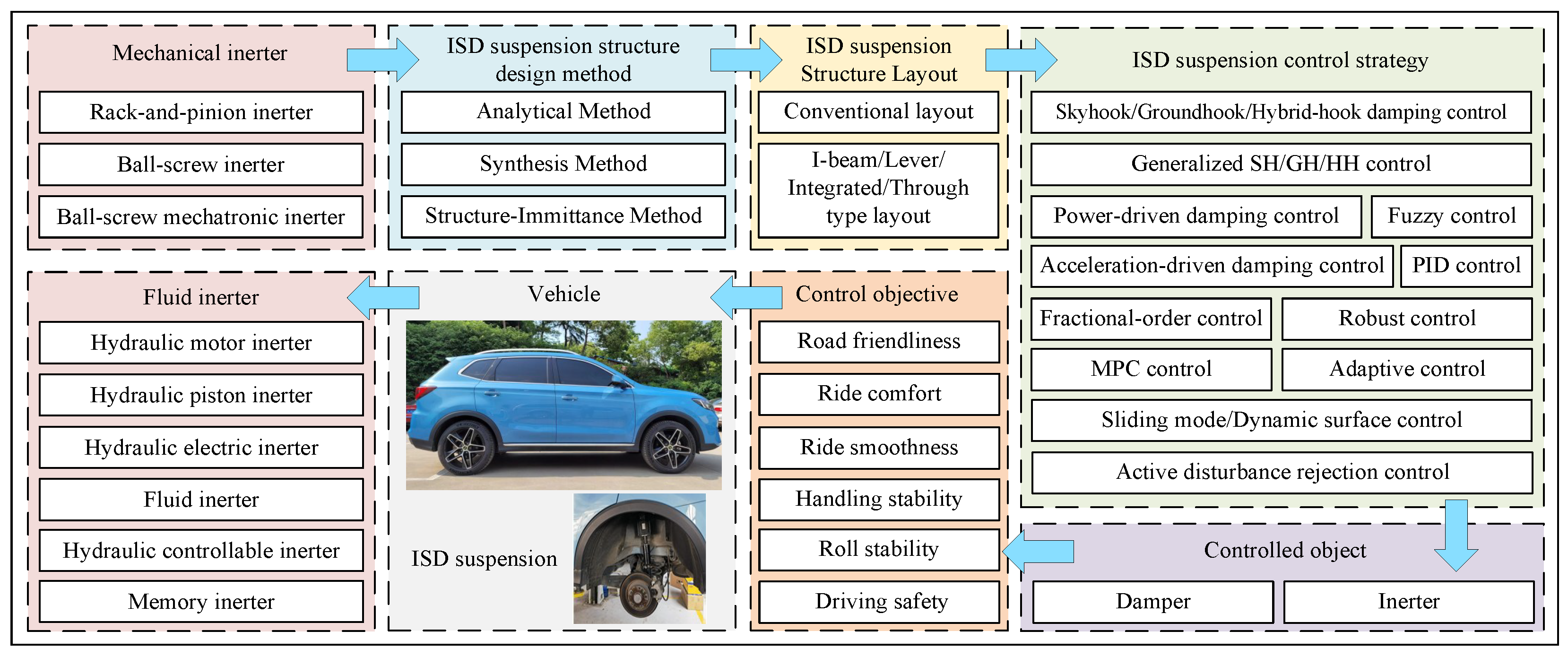
Figure 1. The flowchart of the inerter application.
Machines 13 00779 g001
Figure 2. The analogy theory between mechanical system and electric system.
Machines 13 00779 g002
Figure 3. Rack-and-pinion inerter: (a) diagram; (b) photograph [13].
Machines 13 00779 g003
Figure 4. Ball-screw inerter: (a) diagram; (b) photograph [17].
Machines 13 00779 g004
Figure 5. Ball-screw mechatronic inerter: (a) diagram; (b) photograph [17].
Machines 13 00779 g005
Figure 6. Hydraulic motor inerter: (a) diagram; (b) photograph [17].
Machines 13 00779 g006
Figure 7. Hydraulic piston inerter.
Machines 13 00779 g007
Figure 8. Hydraulic electric inerter: (a) diagram; (b) photograph [42].
Machines 13 00779 g008
Figure 9. Fluid inerter: (a) external helical tube fluid inerter; (b) internal helical tube fluid inerter.
Machines 13 00779 g009
Figure 10. Hydraulic controllable inerter: (a) diagram; (b) photograph [62].
Machines 13 00779 g010
Figure 11. Hydraulic controllable inerter: (a) Diagram, (b) Photograph [66].
Machines 13 00779 g011
Figure 12. Hydraulic controllable inerter: (a) diagram; (b) photograph [67].
Machines 13 00779 g012
Figure 13. Memory inerter: (a) diagram; (b) photograph [68].
Machines 13 00779 g013
Figure 14. Hydraulic controllable inerter: (a) diagram; (b) photograph [71].
Machines 13 00779 g014
Figure 15. Breakdown phenomenon: (a) before breakdown; (b) after breakdown.
Machines 13 00779 g015
Figure 16. (a) Two-stage series ISD suspension; (b) two-stage series ISD suspension.
Machines 13 00779 g016
Figure 17. (a) Equivalent impedance network diagram; (b) two ISD suspension structures.
Machines 13 00779 g017
Figure 18. Eight ISD suspension structures.
Machines 13 00779 g018
Figure 19. Eight improved ISD suspension structures.
Machines 13 00779 g019
Figure 20. Four ISD suspension structures.
Machines 13 00779 g020
Figure 21. Diagram of the steps for constructing the ISD suspension structure.
Machines 13 00779 g021
Figure 22. (a) Ideal skyhook damping suspension system; (b) passive skyhook damping suspension system.
Machines 13 00779 g022
Figure 23. (a) Ideal groundhook damping suspension system; (b) passive groundhook damping suspension system.
Machines 13 00779 g023
Figure 24. (a) Passive DVA; (b) DVA mechanical system network diagram; (c) schematic of the improved DVA; (d) ISD suspension structure.
Machines 13 00779 g024
Figure 25. ISD suspension structures: (a) synthesis; (b) ideal; (c) improved.
Machines 13 00779 g025
Figure 26. ISD suspension structures: (a) first-order; (b) second-order; (c) third-order.
Machines 13 00779 g026
Figure 27. (a) Bridge network; (b) bridge equivalent network; (c) Δ and Y structure.
Machines 13 00779 g027
Figure 28. (a) Three types of bridge network structures; (b) three types of series-parallel structures.
Machines 13 00779 g028
Figure 29. (a,b) Two network structures.
Machines 13 00779 g029
Figure 30. Integrated inerter: (a) diagram; (b) photograph [118].
Machines 13 00779 g030
Figure 31. Integrated inerter.
Machines 13 00779 g031
Figure 32. (a) Ideal SH quarter model; (b) SH quarter model.
Machines 13 00779 g032
Figure 33. (a) Ideal GH quarter model; (b) GH quarter model.
Machines 13 00779 g033
Figure 34. (a) Ideal HH quarter model; (b) HH control quarter model.
Machines 13 00779 g034
Table 1. Comparison of different structural types and characteristics of inerter [72].
Inerter TypeCharacteristics
Rack-and-pinion inerter• Gear backlash
• Moderate durability
• Large inertial amplification effect
Ball-screw inerter• Moderate friction
• Large inertial amplification effect
• Back clearance between ball and screw
Ball-screw mechatronic inerter• High adaptability
• Back clearance between ball and screw
• Capable of realizing network structures
Hydraulic motor inerter• Simple structure
• High loading capacity
• Strong nonlinearity and damping effect
Hydraulic piston inerter• High loading capacity
• Limited in dynamic response speed
• Strong nonlinearity and damping effect
Hydraulic electric inerter• Complicated structure
• High loading capacity
• Capable of realizing network structures
Fluid inerter• High loading capacity
• Low-friction structure
• Strong nonlinearity and damping effect
Memory inerter• High adaptability
• High loading capacity
• Exhibiting memory effect
Table 2. Impedance expressions of eight network structures.
StructureImpedance ExpressionStructuresImpedance Expression
S 1 Z 1 ( s ) = b c s 2 b c ( 1 / k ) s 3 + b s 2 + c s S 5 Z 5 ( s ) = b c s 2 + c k b s 2 + c s + k
S 2 Z 2 ( s ) = b s 2 + c s + k s S 6 Z 6 ( s ) = b c s 2 + b k s + c k b s 2 + c s
S 3 Z 3 ( s ) = b s 2 + c s b ( 1 / k ) s 3 + c · ( 1 / k ) s + s S 7 Z 7 ( s ) = b c ( 1 / k ) s 3 + b s 2 + c s c ( 1 / k ) s + s
S 4 Z 4 ( s ) = b c s 2 + b k s b s 2 + c s + k S 8 Z 8 ( s ) = b c ( 1 / k ) s 3 + b s 2 + c s b ( 1 / k ) s 3 + s
Table 3. Overview of control methods for ISD suspension systems.
Control MethodControlled ObjectReference(s)
FD-SH and adaptive controlInerter[155]
Generalized SHDamper and inerter[156]
GH and adaptive controlInerter[158]
Generalized GHDamper[159]
HHDamper[163]
Generalized HHDamper and inerter[164,165]
HH and MPCInerter[166]
FD-HH and adaptive controlInerter[167]
ADD and SMCInerter[170]
HH and SH-ADDDamper[171]
SH-PDDInerter[173]
PDD and FD-SMCInerter[174]
Fuzzy controlDamper[175]
Robust controlActuator[176,177]
FD-PIDInerter[178]
ADRCInerter[179]
Dynamic surface controlInerter[180]
Disclaimer/Publisher’s Note: The statements, opinions and data contained in all publications are solely those of the individual author(s) and contributor(s) and not of MDPI and/or the editor(s). MDPI and/or the editor(s) disclaim responsibility for any injury to people or property resulting from any ideas, methods, instructions or products referred to in the content.