1. Introduction
The demand for high-performance actuation systems that offer high power density, superior energy efficiency, and precise motion control is a primary driver of innovation across sectors such as industrial automation, mobile robotics, aerospace, and heavy-duty machinery [
1,
2,
3]. For decades, hydraulic systems have been indispensable in these domains due to their great force and torque capabilities and inherent robustness [
4]. However, conventional servo-valve-controlled hydraulic systems are plagued by significant throttling losses, leading to poor energy efficiency [
5,
6], which also leads to increased maintenance costs and reduced operational reliability [
7]. In response to these limitations, digital hydraulic technology has surfaced as a promising alternative to conventional hydraulic systems, demonstrating marked superiority in energy conservation, precision control, and system integration capabilities. Digital hydraulic systems fundamentally rely on two governing operational principles: the strategic parallel interconnection of components and advanced switching methodologies. These techniques regulate system output either by dynamically reconfiguring the discrete states of constituent elements or through precisely modulated pulse-width control mechanisms. This paradigm enhances the operational efficiency and dynamic control characteristic of hydraulic pumps and motors through discrete-valued components [
8,
9,
10].
Despite its promise, the widespread adoption of digital hydraulic motors is hindered by a fundamental challenge: inherent flow and pressure pulsations. The pulsations are a direct consequence of the discrete displacement mechanism and the finite number of piston units [
11]. The abrupt velocity transitions of reciprocating pistons induce pronounced flow discontinuities, which serve as the principal excitation mechanism for structural vibrations and noise propagation within hydraulic circuits.
This pulsation is a primary source of mechanical vibration, acoustic noise, and operator fatigue [
12,
13] More critically, it can degrade control accuracy, excite structural resonances, and lead to premature component wear, thereby compromising the overall performance and lifespan of the hydraulic system [
14,
15,
16]. This necessitates comprehensive pulsation mitigation strategies for optimal performance and operational durability. Moreover, persistent pulsatory phenomena accelerate component degradation, diminish energy conversion efficiency, and may precipitate catastrophic system failure. Consequently, significant research has been dedicated to mitigating these pulsations.
Conventional approaches to pulsation mitigation in hydraulic systems include passive techniques, such as the use of hydraulic accumulators, Helmholtz resonators, and specially designed hydraulic hoses [
17,
18]. Attenuators with pressurized gas are commonly employed in industrial applications for broadband pulsation cancellation and have the additional advantage of absorbing pressure shocks in the hydraulic system. However, these traditional solutions often introduce trade-offs between system response time, energy efficiency, and overall system complexity. While simple and robust, these passive solutions are often bulky and are only effective over a narrow frequency band, limiting their utility in variable-speed applications [
19] Active mitigation strategies have therefore gained considerable attention. These methods involve introducing a secondary actuator or control mechanism to cancel the pulsation at its source. Examples include the use of high-bandwidth piezoelectric actuators to inject anti-phase flow [
20] or the implementation of active damping circuits using fast-switching valves [
21]. While these active methods can offer superior broadband performance, they often introduce significant system complexity, increase energy consumption, and require sophisticated real-time control, which can be challenging to implement robustly [
22]. Researchers have been exploring digital hydraulic solutions to address these challenges. Digital hydraulic pumps and motors typically utilize a collection of on/off valves instead of throttling control valves to avoid energy dissipation commonly present in conventional hydraulic control systems [
23]. The Digital Hydraulic Power Management System employs a centralized pump-motor transformer with multiple independent outlets to enhance system flexibility and efficiency. Mathematical modeling approaches have been developed to better understand and mitigate system pulsations. Studies have focused on identifying the components of the amplitude–frequency spectrum of pressure pulsations in hydraulic systems to develop more effective countermeasures, specifically those targeting the suppression of pulsation-induced pressure oscillations [
11].
Despite significant progress in digital hydraulics, several critical gaps remain in the effective mitigation of pulsations and the development of control strategies specifically tailored for digital hydraulic motors. The integration of variable speed control with digital hydraulic technologies presents promising opportunities for improving both energy efficiency and system controllability. However, comprehensive solutions that simultaneously address pulsation mitigation while optimizing motor control remain limited. Parallel to the efforts in mechanical and hydraulic pulsation damping, the control strategy for the digital motor itself is a critical research frontier. The objective is to modulate the discrete outputs to achieve smooth, continuous control of speed or torque. Pulse-Width Modulation (PWM) and Pulse-Frequency Modulation (PFM) are widely adopted techniques to approximate intermediate output levels [
24]. However, these methods often involve a trade-off between control resolution and switching frequency; high-frequency switching improves smoothness but increases switching losses and valve wear [
21]. More advanced control schemes, such as Model Predictive Control (MPC), have been proposed to optimize the switching sequence by considering future system states, thereby minimizing ripple and losses simultaneously [
25]. Nevertheless, the computational burden of MPC can be substantial, and its performance is highly dependent on the accuracy of the system model, which can be difficult to obtain, especially when accounting for complex fluid dynamics and load variations [
26].
Additionally, while digital hydraulics aims to eliminate throttling loss, studies have demonstrated that switching valves can effectively substitute servo valves in fulfilling the flow distribution requirements of digital hydraulic motors, enhancements in controllability can be achieved without a concomitant rise in energy expenditure, underscoring the demand for more complex control methodologies.
This paper aims to address these gaps by proposing innovative designs for pulsation mitigation integrated with effective control strategies specifically developed for digital hydraulic motors. We present a comprehensive approach that considers both the mechanical aspects of pulsation mitigation and the control methodologies necessary for optimal digital hydraulic motor operation efficiency. Distinct from conventional servo-valve-regulated systems, our methodology demonstrates intrinsic advantages in enhanced contamination resilience and superior volumetric efficiency.
The outline of this article is organized as follows:
Section 2 introduces the digital hydraulic motor configuration working principle;
Section 3 presents the theoretical foundation and mathematical modeling of pulsation phenomena in digital hydraulic motors; in
Section 4, specific design for pulsation mitigation is proposed; in
Section 5, detailed valve modeling and efficiency calculations are carried out;
Section 6 elaborates on the developed control strategies;
Section 7 outlines the experimental setup and presents the validation results; Finally,
Section 8 concludes the article and discusses future work.
2. Working Scene and Demand of Digital Hydraulic Motor
The digital hydraulic motor system described in this paper integrates an absolute angle displacement encoder to establish precise phase synchronization between piston motion and rotor positioning. By eliminating traditional intermediary transmission mechanisms via direct-drive actuation design, the system achieves enhanced compactness and better power density. Real-time closed-loop positional control, enabled by the encoder’s high-resolution feedback, ensures deterministic actuation of the flow distribution valve while minimizing phase drift, thereby sustaining dynamic response fidelity under operational load variations.
Figure 1 illustrates the working architecture of the digital hydraulic motor, comprising an array of piston-valve units, each unit is integrated with dual flow distribution valves for flow distribution during actuation. While working, these valves govern precisely timed oil suction/discharge cycles, converting hydraulic energy into linear piston motion, which is subsequently transformed into rotational torque via an integrated internal cam mechanism. The motor’s load-bearing rotor couples directly to the cam, ensuring kinetic transfer efficiency.
Figure 1b details the circumferential piston arrangement, with one unit shown in an active expansion state. In the discharge phase, the outlet distributing valve (ODV) opens to purge spent fluid, and in the suction phase, the inlet distributing valve (IDV) opens to admit pressurized oil to drive the cam and yield output torque.The red region denotes the high pressure, the blue region denotes the low pressure.
In the diagram, T denotes the torque output by the piston unit to the motor rotor, represents the rotational speed of the motor rotor, and signifies the radial velocity of the piston outward along the motor rotor diameter, facilitating work performed on the motor rotor.
In the design of the digital hydraulic motor, the piston is strategically positioned within the stator, while the output drive mechanism is configured on the rotor, situated at the outer circumference. In contrast to conventional hydraulic motors, the piston utilizes a roller structure at its terminus, supplanting the previous friction pair configuration, which markedly diminishes power loss attributed to friction. Acknowledging the risk of external leakage between the rotor and stator, a sophisticated combined sealing technology is implemented between the piston and the housing, effectively eliminating the possibility of external leakage. Moreover, a high-speed switching valve facilitates the distribution of flow between the piston chamber and the high and low-pressure oil circuits, ensuring that it remains impermeable when closed, thereby preempting any leakage-induced power losses. As a result of these groundbreaking innovations, the theoretical operational efficiency of the digital hydraulic motor substantially surpasses that of hydraulic motors employing traditional flow distribution methodologies.
The radial digital piston hydraulic motor of this configuration necessitates precise regulation of the distributor valve’s opening and closing in order to alter the connection dynamics between the piston chamber and the hydraulic source. Let
denote the pressure within the piston chamber. When
, the objective is to optimize
by exclusively linking the piston to the high-pressure oil source, while ensuring that the IDV remains open, under the assumption that the pressure in the piston chamber aligns with that of the oil source. Conversely, when
, the aim is to minimize
by diverting the piston solely to the return oil; the low-pressure distributor valve remains open, thereby aligning the pressure in the piston chamber with the return oil pressure.
Figure 2 illustrates the ideal power curve of the piston unit alongside the corresponding distribution relationship.
The symbol + denotes that IDV is opened while ODV is closed, whereas the symbol − signifies that ODV is opened and IDV is closed. The red region denotes that high-pressure hydraulic oil flows into the piston chamber, whereas the blue region illustrates the return flow of oil from the chamber to the drain.
3. Torque Pulsation Characteristics
In the course of operating the motor drive, we anticipate that the digital hydraulic motor will possess the capability for torque adjustment. Consequently, when integrating the digital hydraulic motor into the traction system, two critical issues must be resolved: first, the method by which to mitigate torque fluctuations within the motor, and second, the approach to implement effective torque adjustment functionality for the motor.
3.1. Torque of Motor
Each work cycle is bifurcated into two distinct phases: the suction phase and the discharge phase. During the suction phase, the piston extends radially outward, exerting force on the motor rotor and thereby generating torque that propels the wheel. During the discharge phase, the piston chamber is connected to the drain via ODV, resulting in minimal driving torque resistance.
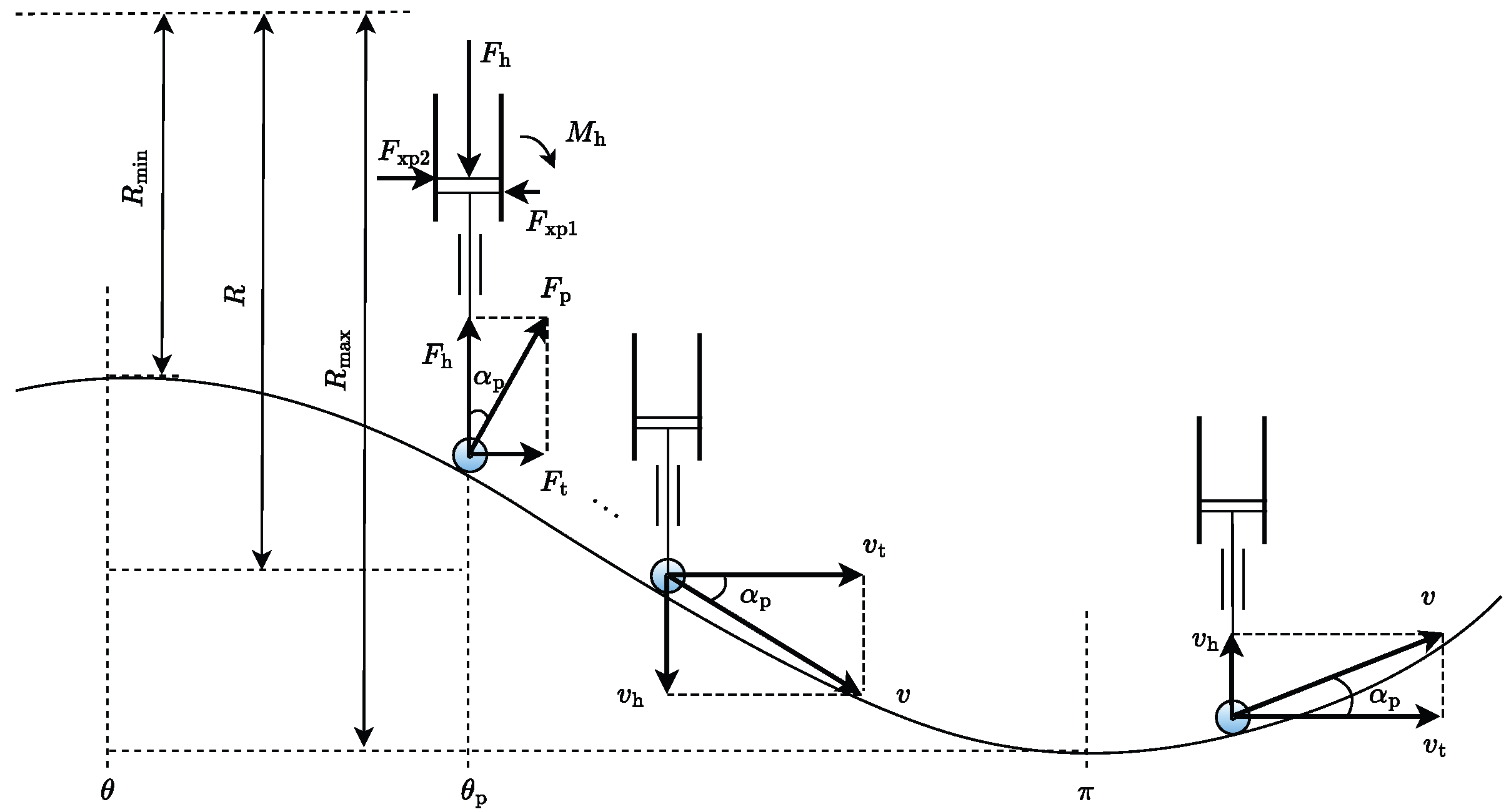
It is hypothesized that the tangential angle between the roller and the rotor’s outer contour may be omitted in force analysis, given the roller’s negligible diameter relative to the motor rotor. The ensuing force equilibrium is derived as follows.
Figure 3 illustrates the relationship between the opening of IDV and ODV during the motion of the piston and the shape of the motor rotor. The internal curve is extended in the circumferential direction, which comprises an integer number
m of periodic functions.
Figure 4 illustrates the decomposition of velocity and the analysis of forces involved in the piston movement process.
Based on the velocity and force analysis depicted above, equations can be derived as
Given a predetermined law of piston motion, the instantaneous torque of the digital hydraulic motor can be computed utilizing the principle of equal instantaneous power. In the design phase of the motor rotor’s internal contour, it is imperative to consider the morphological attributes of this contour and to investigate the correlation between the motor torque and the internal curve.
During the discharge phase, the piston moves inward due to the contact interaction with the internal curve. At this stage, the piston chamber is connected to the low pressure, which leads to minimal resistance, allowing the corresponding braking torque to be considered negligible. Consequently, the analysis will concentrate on the suction phase.
The internal curve of the motor is characterized as a periodic function of the motor’s rotational angle.
The partial derivative of the internal curve in the radial direction with respect to the circumferential direction is denoted as
Similarly, by leveraging the relationship that the work performed by the hydraulic oil on the piston is equivalent to the instantaneous power exerted by the piston on the internal curve actuator, one can derive the instantaneous displacement of the i-th piston.
where
is the piston chamber area.
The total instantaneous torque of the motor, denoted as
, is expressed as
where
n is the piston number,
r is the piston stroke.
The angular displacement of the i-th piston exhibits the following dependence on the motor actuator’s rotation angle:
Summing over the pistons, the instantaneous displacement of the motor is given by
represents the connection relationship between the i-th piston and the system’s high pressure and low pressure. The first cycle of the internal curve corresponds to the working cycle of the piston performing work externally, and the expression for
is as follows.
In conjunction with the definition of the piston stroke,
satisfies the following equation.
The instantaneous drive torque of the motor is derived as
3.2. Open-Loop Torque Characteristic
The digital hydraulic motor simulation model shown in
Figure 5 adopts a super-component modeling approach, where each piston unit is represented as an integrated functional block. This modeling strategy accurately captures the torque characteristics of the multi-piston system while maintaining computational efficiency. The motor model properly accounts for tire-road interactions, enabling realistic simulation of dynamic load conditions. The super-component implementation preserves detailed physical behaviors while significantly reducing model complexity compared to conventional component-level simulations.
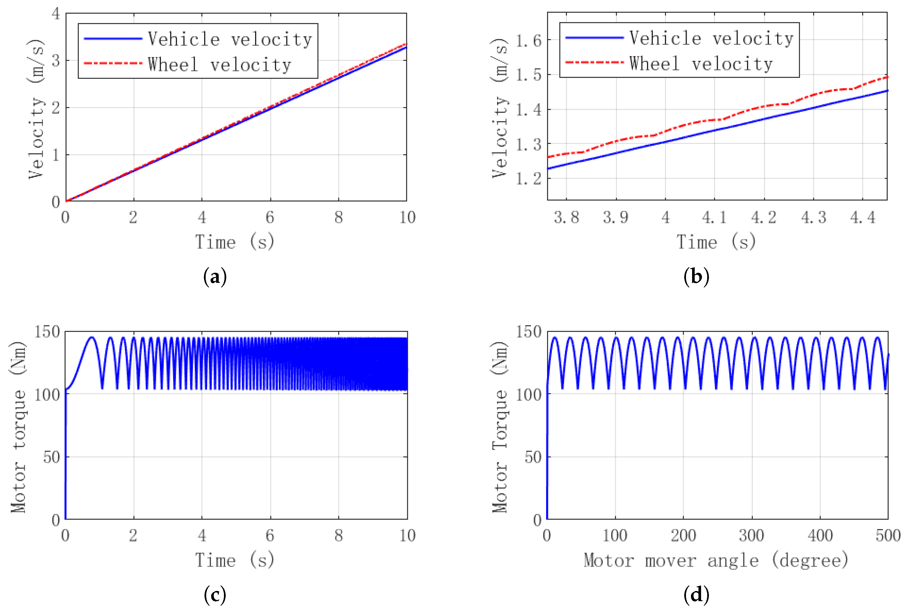
Figure 6 presents the motor’s simulation results under full displacement, open-loop conditions, using a sine function as the internal actuator curve. The distribution method employs Method 1.
As illustrated in
Figure 6d, the instantaneous torque of the motor displays periodic fluctuations corresponding to the rotational angle of the motor actuator. This pronounced torque pulsation results in frequent alterations in wheel speed, imposing cyclic alternating loads on the suspension system, which adversely affects the fatigue life of the driving system.
To ensure consistency between simulation and experimental validation, the parameters listed in
Table 1 employ a scaled-down approach that proportionally reduces system dimensions.
4. Torque Pulsation Mitigation Design
4.1. Principle of Torque Pulsation Elimination
The motion law of the pistons in an axial piston hydraulic motor follows a sine motion law; therefore, the motion law of the pistons is also in a sine form. The pulsation of the discharge can only be reduced by increasing the number of pistons, but it cannot be eliminated. A hydraulic motor with a multi-action internal curve can define the motion rate of the pistons by setting the shape of the internal curve, achieving the goal of maintaining a theoretically constant instantaneous displacement of the motor, thereby eliminating torque pulsation.
The partial derivative of the internal curve
, the working state of the pistons
, and the number of pistons
n are the three main factors that affect the instantaneous displacement of the motor. The design criteria for eliminating torque pulsation can be expressed as follows:
As the pistons chamber transition between high-pressure source and low-pressure drain, the active piston count contributing to effective work output varies discretely. Consequently, upon fixing the motor’s configuration parameters , one must derive a functional mapping to account for this discontinuous variation and maintain theoretically consistent torque production.
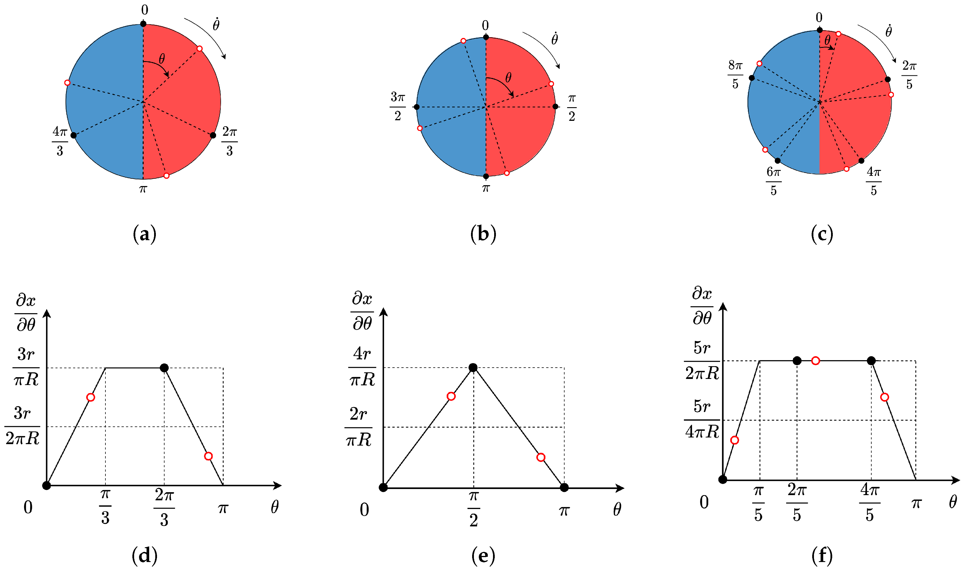
Figure 7 illustrates the principle of eliminating torque pulsation in the motor under three different configurations with
pistons and
internal curves. In the subfigure on the left, the solid black dots represent the phase angles of the pistons when the motor’s moving element is at the zero position, while the hollow red dots represent the phase angles of the pistons when the motor’s moving element has rotated. It can be observed that when the number of pistons is odd, The number of pistons
performing external work has two scenarios
and
, When the number of pistons is even, scenarios
has two situations:
and
.
Subfigure (d), (e), (f) characterize the mathematical correspondence between piston phase orientation and the partial derivative of the cam profile, exhibiting exact conformity with the graphical representation. The black solid dots and red hollow circles denote the piston phase distributions for two distinct operational phases. Under these geometric constraints, the motor’s instantaneous displacement remains invariant—thereby eliminating torque ripple entirely.
For the respective architectural configurations with
, 4, and 5, these conservation relations hold precisely:
The interval where
is located is referred to as the transition interval. The corresponding partial derivative of the internal curve
associated with
can be calculated using eq-rhothetacondition. A summary of the parameters for the torque pulsation elimination principle can be found in
Table 2.
The torque pulsation suppression strategy outlined in
Figure 7 is theoretically sound. However, its partial derivative lacks continuity, resulting in abrupt force discontinuities acting on the pistons, which manifest as undesirable impact-induced vibrations. To address this limitation, the cam profile’s partial derivative optimization method is given. As demonstrated in
Figure 8, the optimized profile employs smooth, differentiable odd-order functions for all transition intervals, ensuring both kinematic continuity and dynamic stability. The red circle denotes the phase of the piston unit.
4.2. Torque Control Method
The number of the piston n can be expressed as the product of a prime number and the number of working groups of the piston.
The total number of pistons (
n) follows a factorization into prime components and the quantity of piston working groups, such that
The output torque of the motor can be finely tuned by regulating the engagement of the piston in the operational process. This is accomplished by permitting only a subset of the pistons to function, thereby aligning the motor’s instantaneous displacement with a predetermined ratio of its maximum instantaneous displacement.
Consequently, the magnitude of the motor’s output torque is contingent upon the number of pistons engaged in the operational process. To regulate the torque while ensuring the absence of pulsation in the output torque, the precision of the motor’s torque adjustment is intricately linked to the number of piston groups capable of participating in the work.
The motor’s torque adjustment
is determined by multiplying the reciprocal of the number of piston working groups by the resolution of the maximum output torque of the motor
.
In the previous section, the parameter derivation of the motor torque ripple elimination principle was completed using a motor configuration with . To enhance the output torque of the motor, the number of inner curves m is generally much greater than 1.
Determine the sufficient conditions so that the motor configuration parameters, denoted as
m and
n, are of great significance to the serial design of digital hydraulic motors.
To enhance the resolution , while maintaining a constant number of pistons n, the minimum value is typically established, often designated as .
4.3. Influence of Parameters on Resolution and Control Error
The simulation was performed using a modified version of the model shown in
Figure 5b, with key adjustments made to the cam profile parameters and the number of piston units. The revised model maintains the super-component architecture while enabling investigation of how these design variables affect the motor’s torque output and dynamic response.
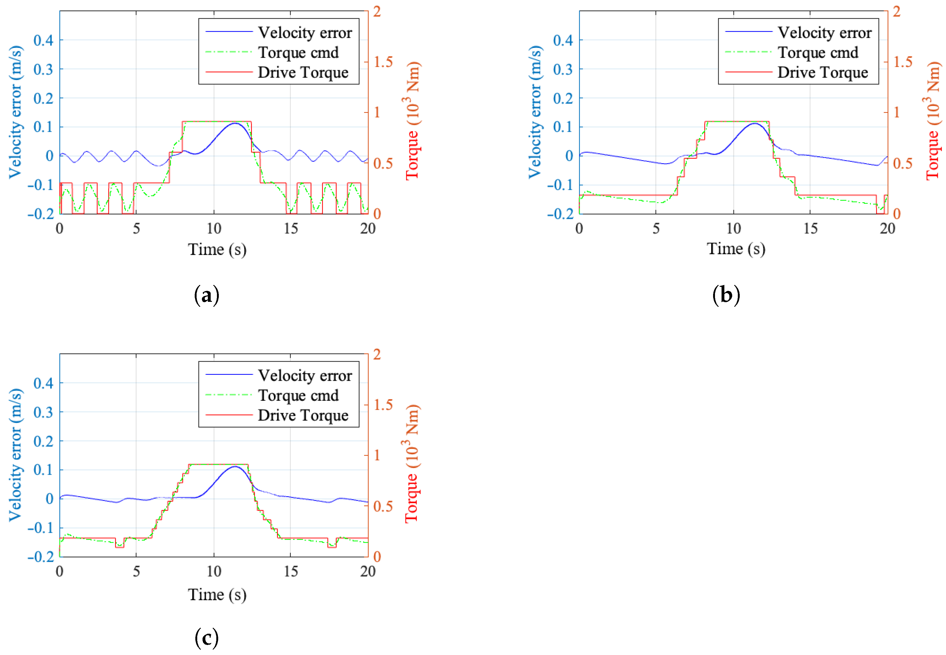
Figure 9 illustrates the impact of different torque resolution levels on the vehicle speed tracking error and the fluctuation of wheel speed. An increase in resolution helps to mitigate the oscillations near the system’s steady-state point and enhances the tracking accuracy of the system.
Figure 10 presents the simulation results under torque resolutions of 1/3, 1/5, and 1/10. The simulation results indicate that digital hydraulic motors with different torque resolutions are capable of achieving closed-loop control of the vehicle velocity.
5. Distribution Modeling and Efficiency Evaluation
5.1. Efficiency Definition
The comprehensive formula for efficiency, in which the motor functions as a power output component, is articulated as the ratio of output power to input power, mathematically represented as follows:
The output power of the hydraulic motor
can be determined by performing an integration of the product of the output shaft torque and the angular velocity with respect to time.
The input power of a motor
can be articulated as the time integral of the disparity between the product of the input flow rate and pressure, and the product of the output flow rate and pressure, augmented by the variation in the motor’s potential energy
.
The primary element is the product difference of the inlet and outlet pressure and flow rates, the pivotal factor is the pressure potential energy
depicted as
The expression of output work contains unknown an variable piston chamber pressure , and the establishment of pressure requires oil to enter and exit the piston chamber, also resulting in throttling loss under the pressure difference between oil and oil flow.
5.2. Hydraulic Dynamic Modeling
To evaluate the influence of oil inflow and outflow on the pressure within the piston chamber, as well as the associated throttling losses, a dynamic characteristics modeling of the oil fluid is undertaken.
By synthesizing the geometric relationships illustrated in
Figure 4 with the established definitions of flow and motion, we can elucidate the correlation between the volume of the piston chamber
and the displacement of the piston unit
x.
where
is the volume of the piston chamber when the piston is in its fully reacted position.
The rate of change of volume within a closed cavity can be expressed as
Under low-speed operating conditions, the piston motor utilizes a composite sealing technique, rendering external leakage negligible in relation to the working fluid flow. Derive the dynamic equation governing the pressure within the piston chamber
.
where
is the effective elastic volume modulus of hydraulic oil. And the flow of IDV
and that of ODV
are illustrated as
where
and
represent the opening of IDV and ODV; the ideal opening can be derived as shown below
The direction of fluid flow is dictated by the sign of the pressure differential, with , denote the angular positions of the inlet distributing valve and the low-pressure valve, and the flow pressure coefficient corresponding to the valve openings is also specified.
The active power conveyed to the motor by the hydraulic oil
is denoted as
5.3. Distribution Loss Considering Phase Deviation
The equation governing output power incorporates the elusive variable of piston chamber pressure, whereas the determination of this pressure necessitates the circulation of oil into and out of the piston chamber. The flow rates of oil both entering and exiting induce throttling losses attributable to the pressure differential. To maximize power output, it is essential to optimize the valve timing—an inherently critical consideration.
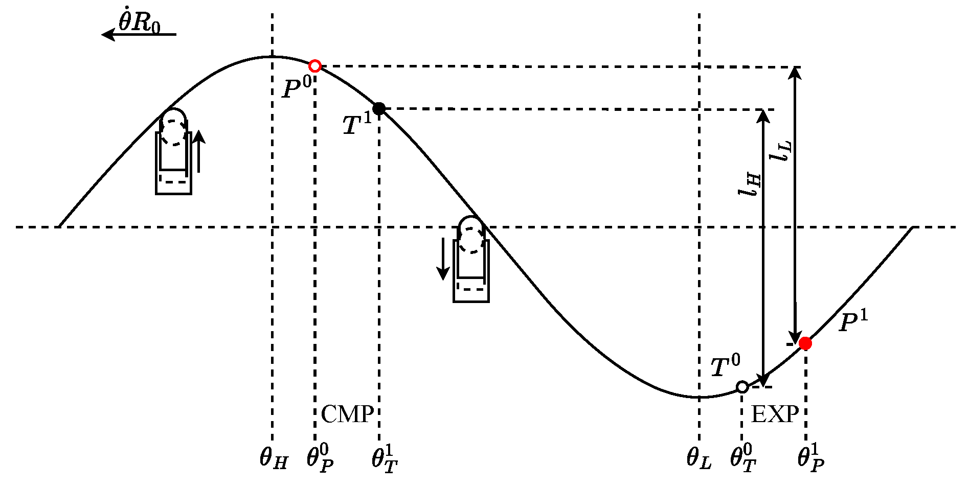
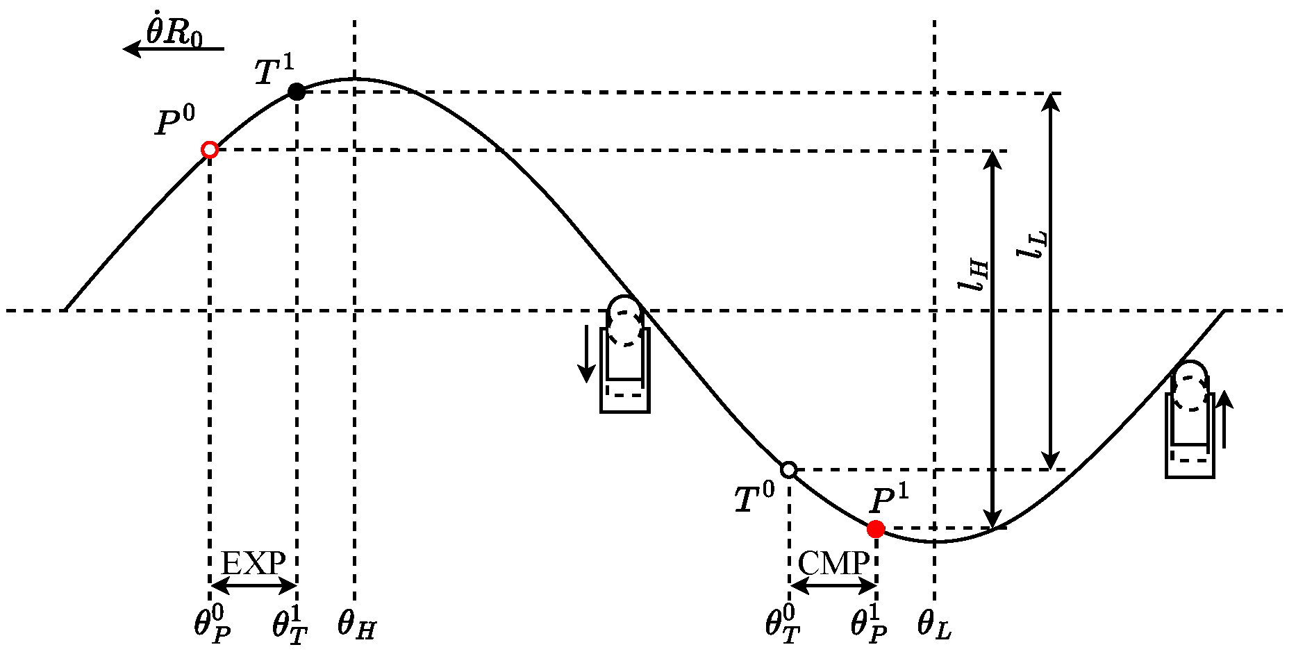
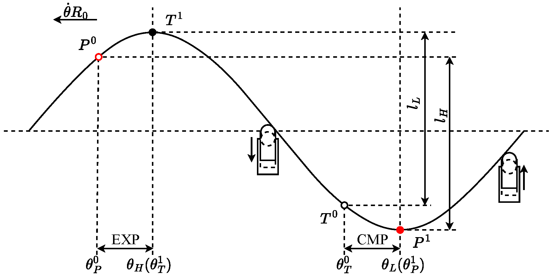
The initiation of the flow distribution valve’s opening occurs subsequent to the optimal flow distribution phase.
The commencement of the flow distribution valve’s opening precedes the optimal flow distribution phase.
The upstream and downstream flow distribution valves exhibit concurrent opening.
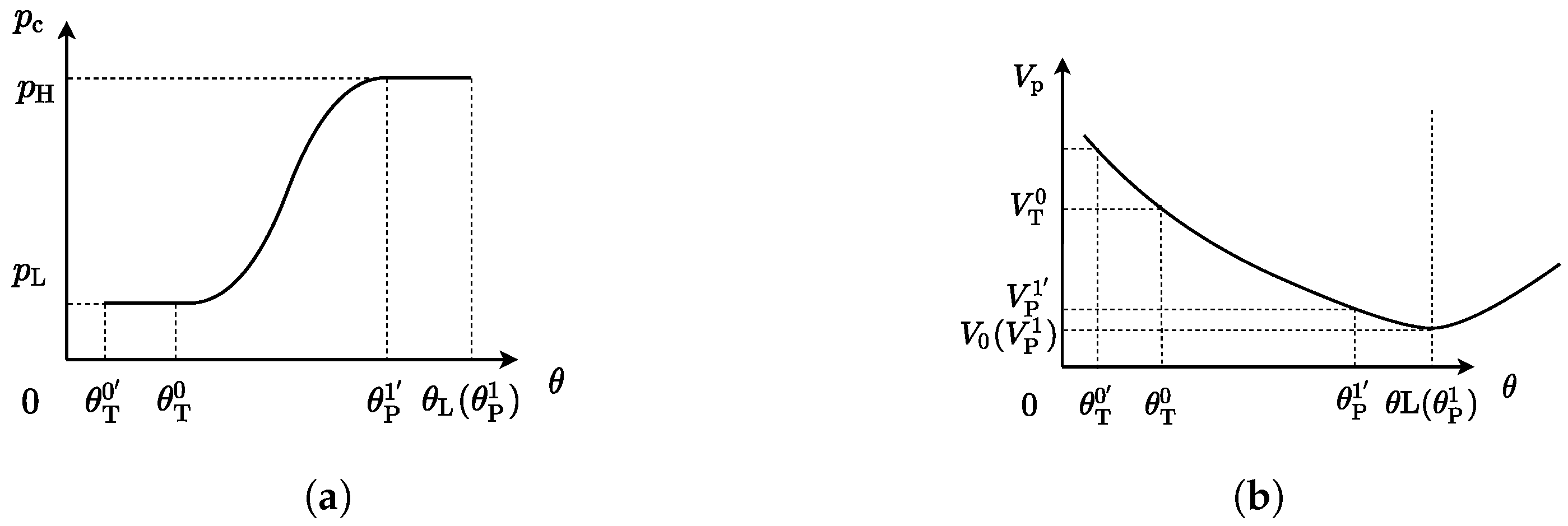
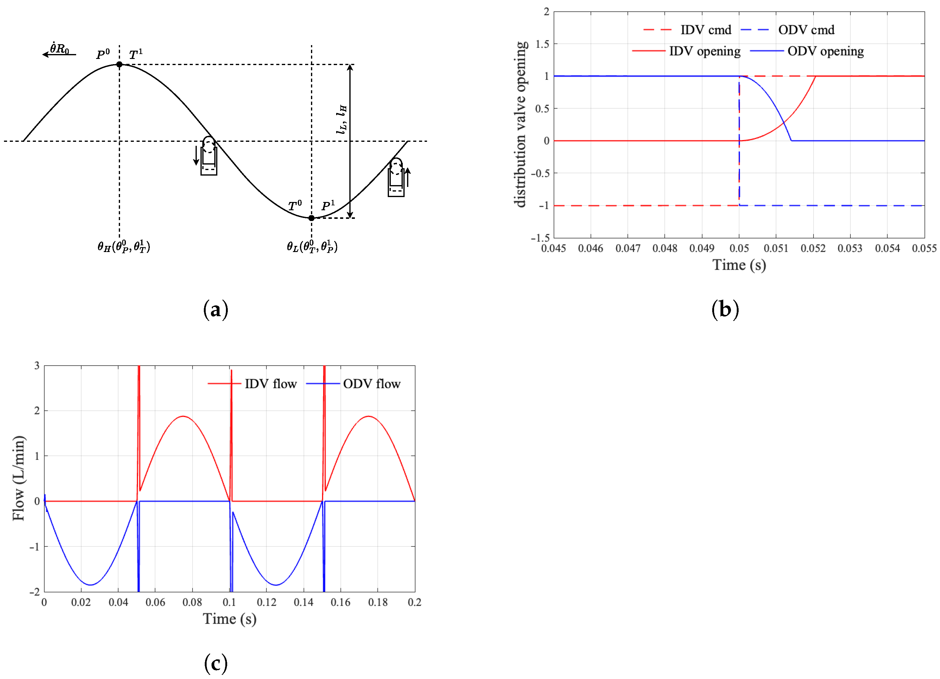
Figure 11 illustrates the power diagram of the piston unit when the opening point of the distribution valve is subject to delay, resulting in a lead over the ideal distribution phase. The red segment signifies the inlet distributing valve being opened while the low-pressure valve remains closed, thereby facilitating the connection of the piston unit chamber to high pressure. Conversely, the blue segment denotes the low-pressure valve opening with the inlet distributing valve closed, thereby linking the piston unit chamber to low pressure. The “+” section represents the piston unit during both the forward and return strokes.
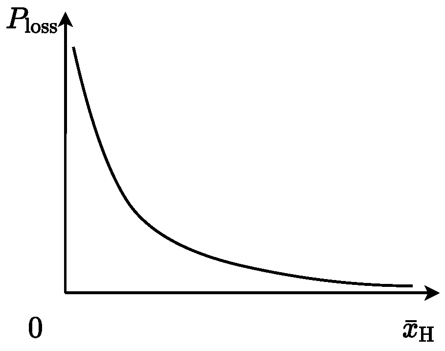
When the switching time aligns precisely with an integer multiple of a predetermined cycle, the oil suction and discharge flow rates of the motor can seamlessly correspond to the theoretical flow distribution relationship dictated by the distribution valve. However, should there be a delay in the flow distribution phase angle, the oil suction and discharge flow rates may turn negative, leading to a negative output power from the motor. This scenario engenders a deceleration torque during the motor’s operation, consequently diminishing its overall driving efficiency. Likewise, an advancement in the flow distribution phase angle can precipitate analogous detrimental effects.
The relationship between the phase of the distributing angle bias
and the motor efficiency is established when the given condition
is met.
The motor efficiency
is derived by integration as
7. Experiment Validation
7.1. Principle Prototype
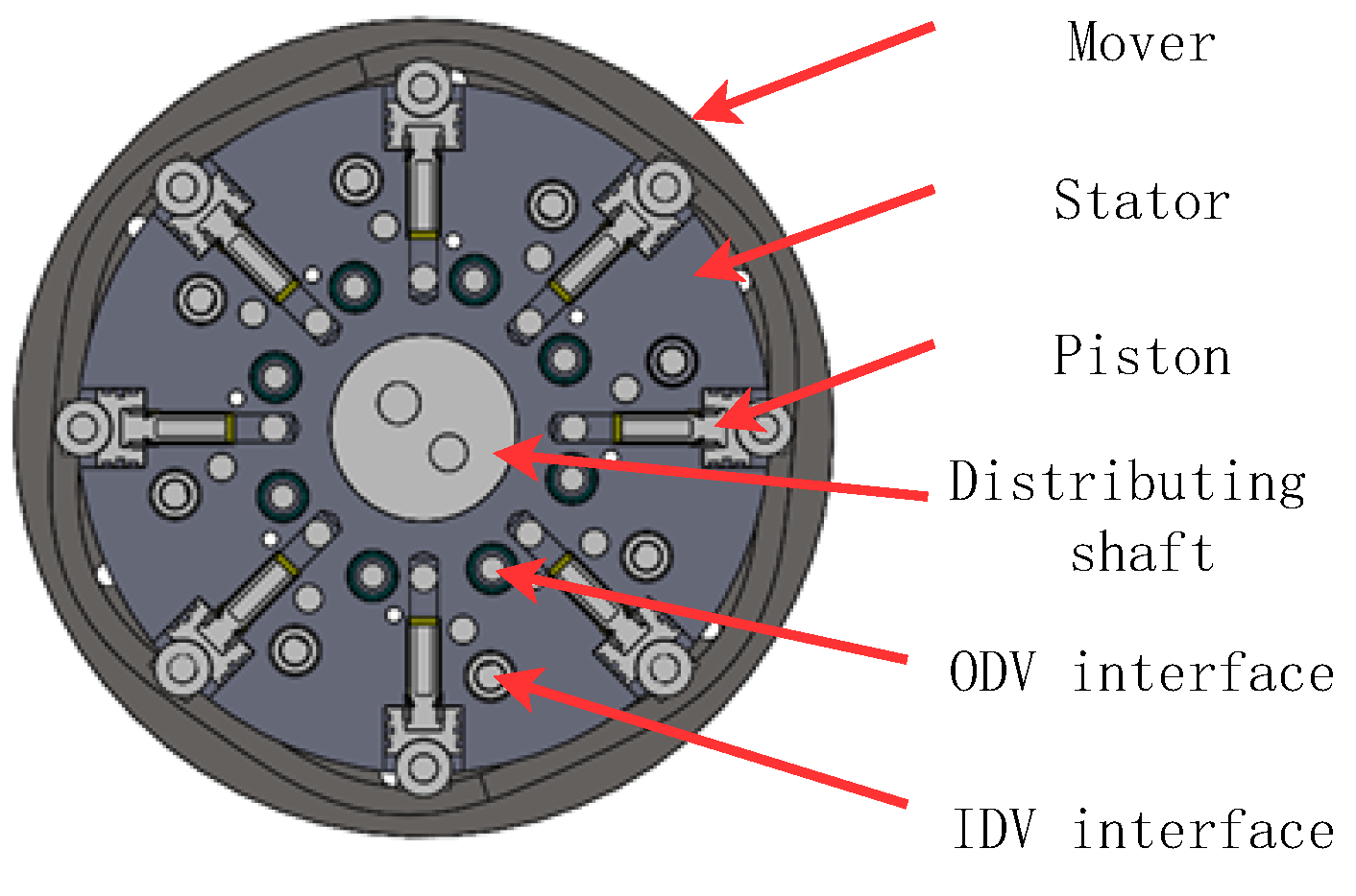
The developed radial digital hydraulic motor prototype, shown in
Figure 22, features a configuration with six cam profiles and eight piston units. The design incorporates needle roller bearings at all piston-rotor contact interfaces to significantly reduce friction losses while maintaining precise motion control.
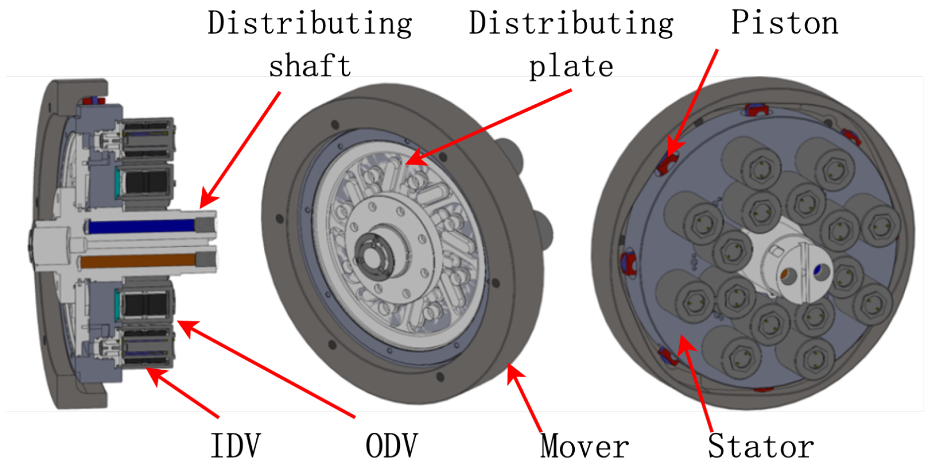
The functional elements of the hydraulic motor are illustrated in
Figure 23, which comprises an inner cam rotor, eight pairs of piston units, a flow distribution plate, a flow distribution shaft, eight IDVs, and eight ODVs. The overall architecture of the digital hydraulic motor prototype is notably compact.
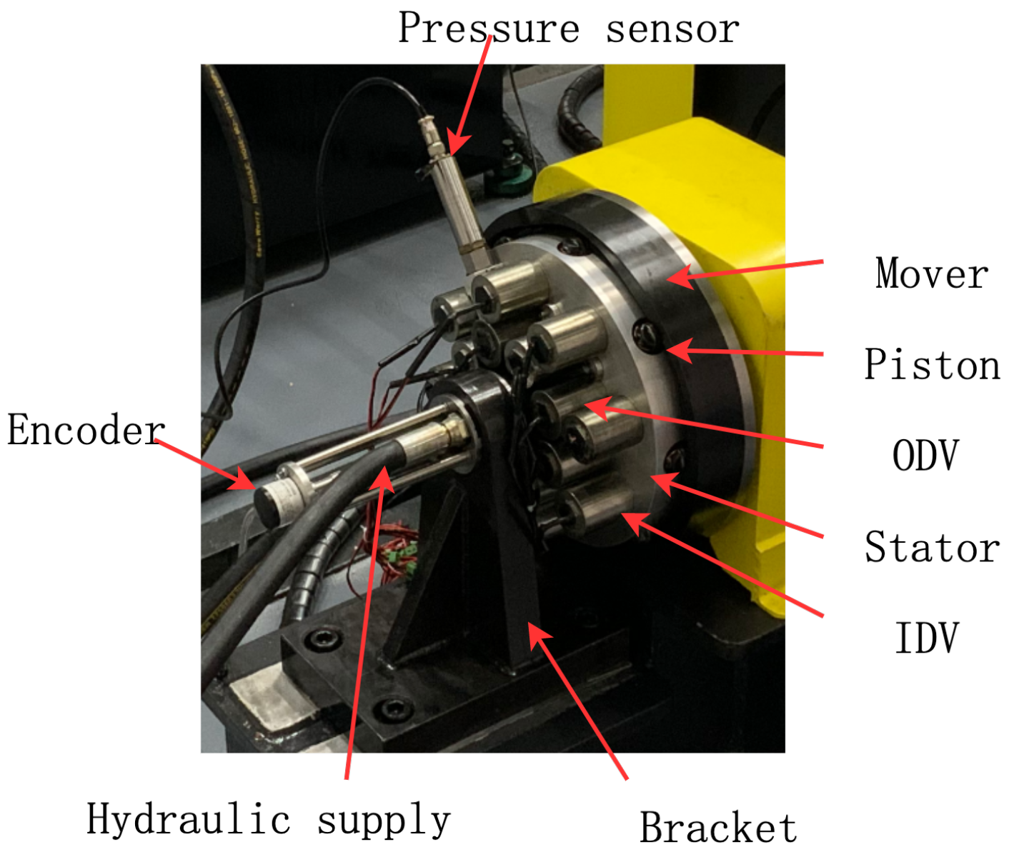
The physical prototype of the radial digital hydraulic motor is shown in
Figure 24. To facilitate testing, sensors such as pressure transducers and encoders were installed. The motor shaft is supported in a dual-bearing configuration, while the hydraulic supply and return circuits are routed through the remote end of the fluid distribution shaft, faithfully simulating the spatial constraints of vehicular mounting applications.
7.2. Test Bench
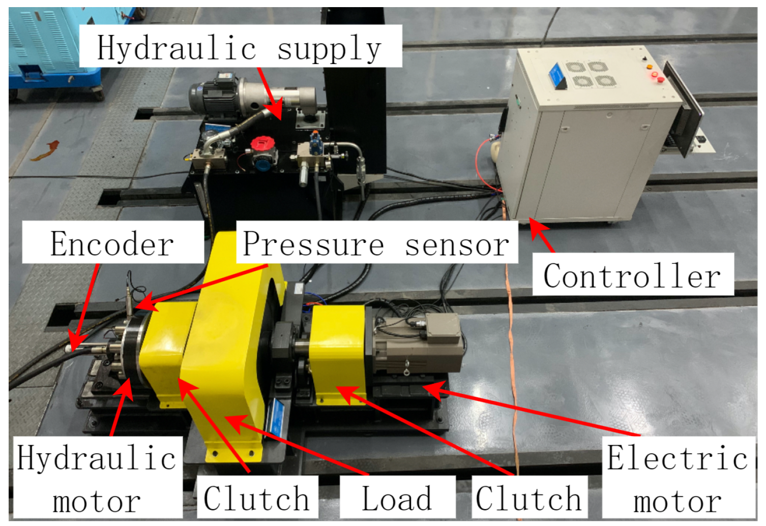
The testing bench depicted in
Figure 25 consists of three functional modules: the hydraulic motor proposed, the inertia wheel, the electric motor for loading, and the hydraulic power source. Each moving component is connected via a clutch and coupling assembly. The inertia wheel contained in the yellow shell provides a vehicle-equivalent mass moment simulation.
A pneumatically controlled emergency braking subsystem provides instantaneous stopping capability for the inertia wheel, protecting the experimental apparatus from rotational wear while ensuring operational safety during high-velocity testing.
To establish phase synchronization for the distribution valve, the controller utilizes angular displacement feedback from an encoder mounted on the motor’s rotor. Real-time pressure monitoring in the plunger chamber and hydraulic circuit facilitates phase adjustment algorithms. System safety is ensured through automatic hydraulic unloading upon overpressure detection.
7.3. Methodology
We employed a fixed displacement pump as the oil supply; system performance was evaluated under consistent test conditions, including identical pressure settings, flow rates, and load characteristics.
The correlation between the motor’s maximum achievable speed and its overall operational efficiency should reveal that higher rotational speeds consistently corresponded to improved efficiency levels.
7.4. Experimental Results
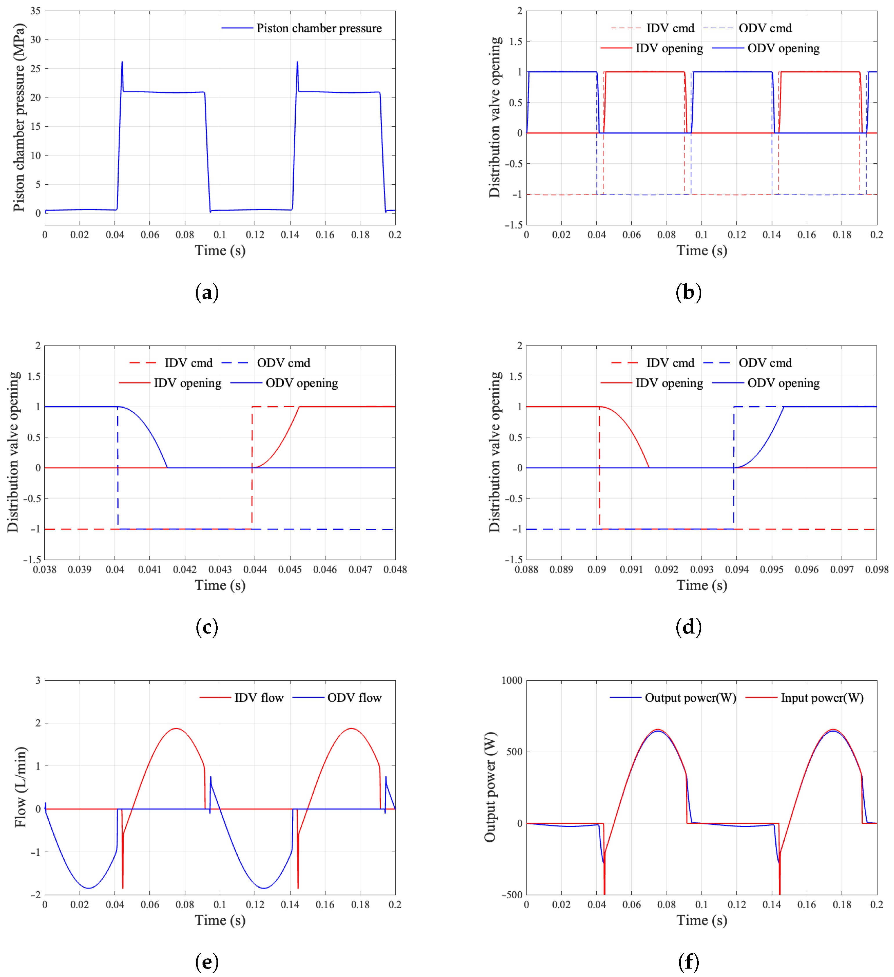
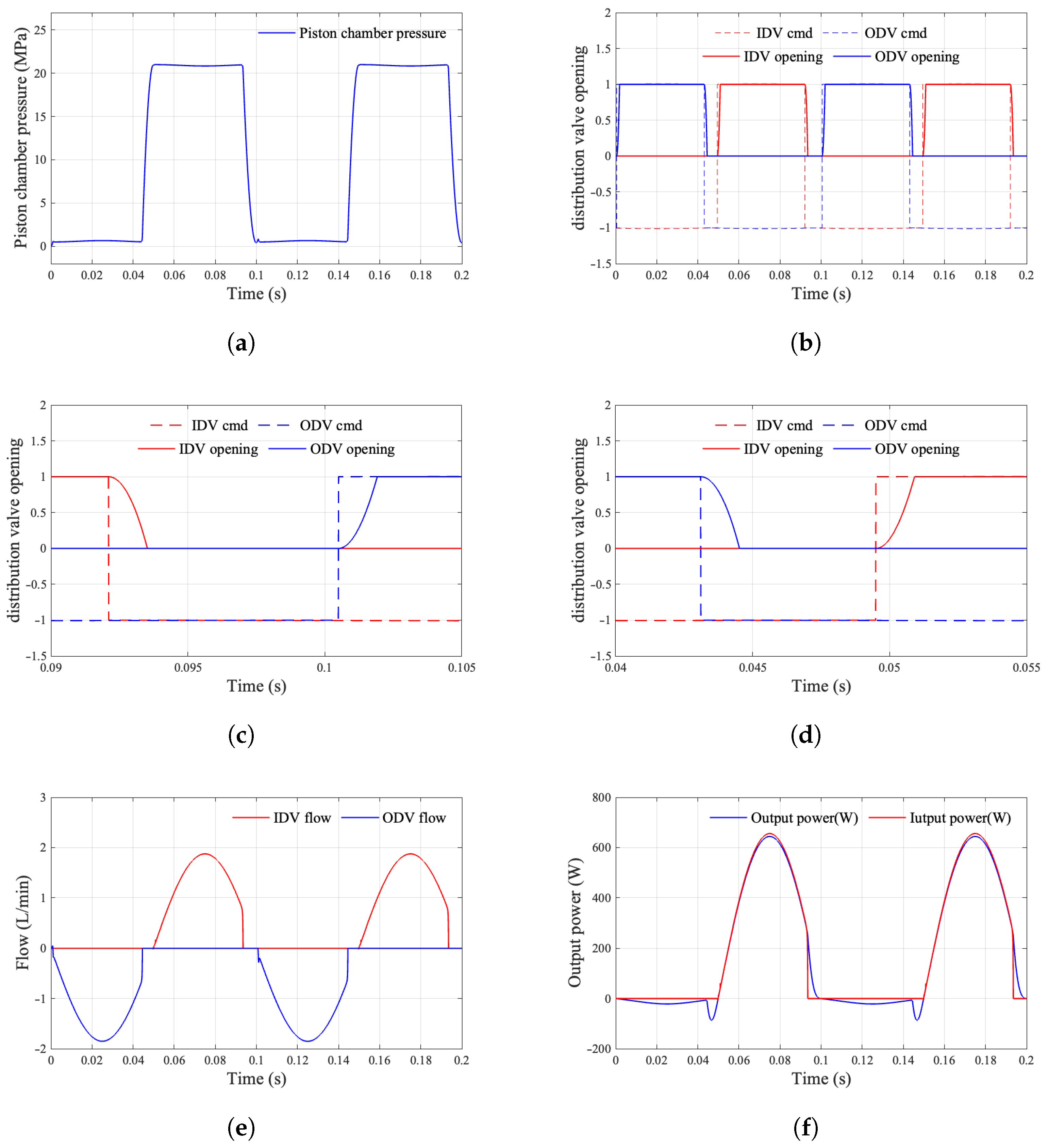
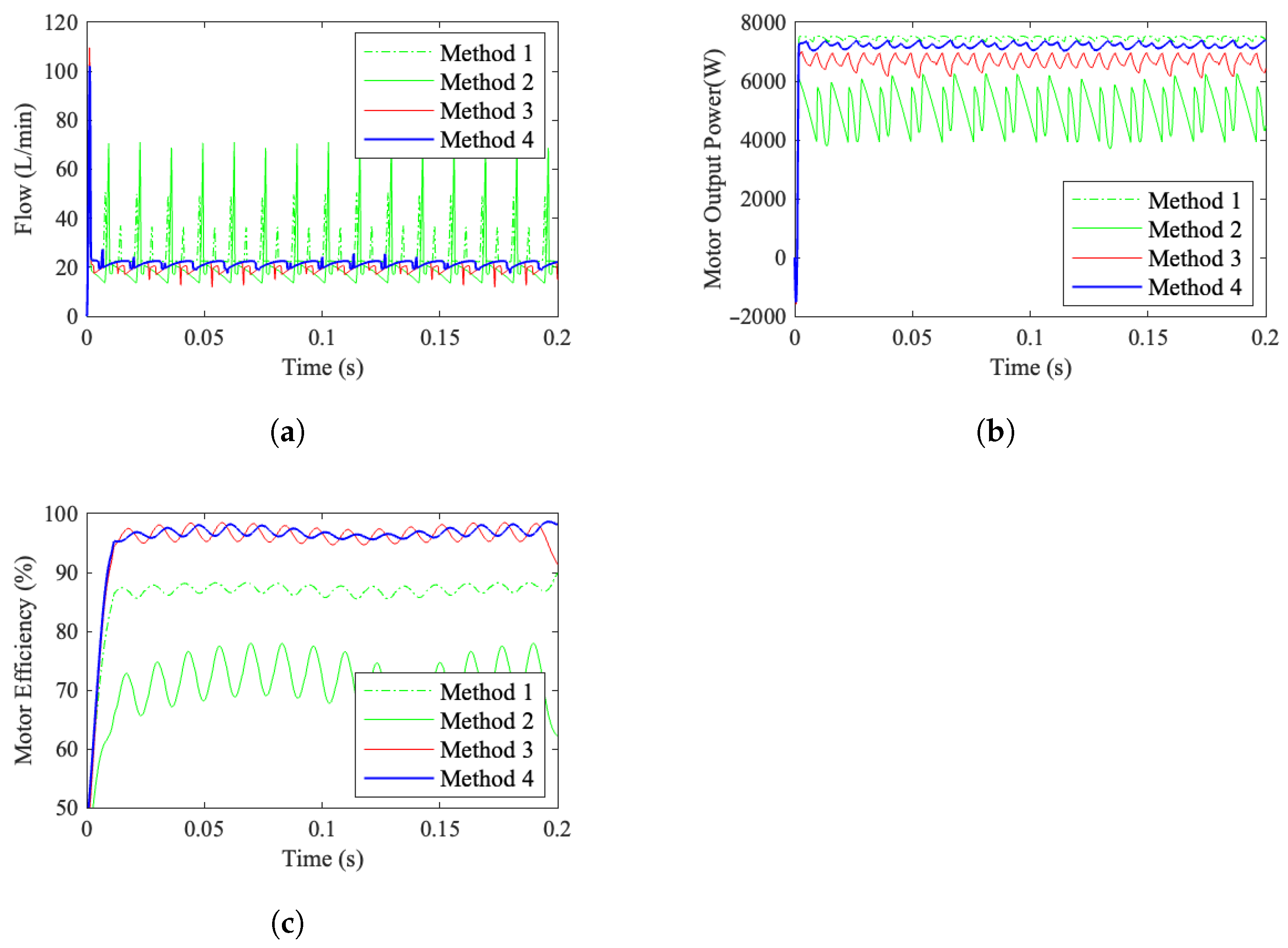
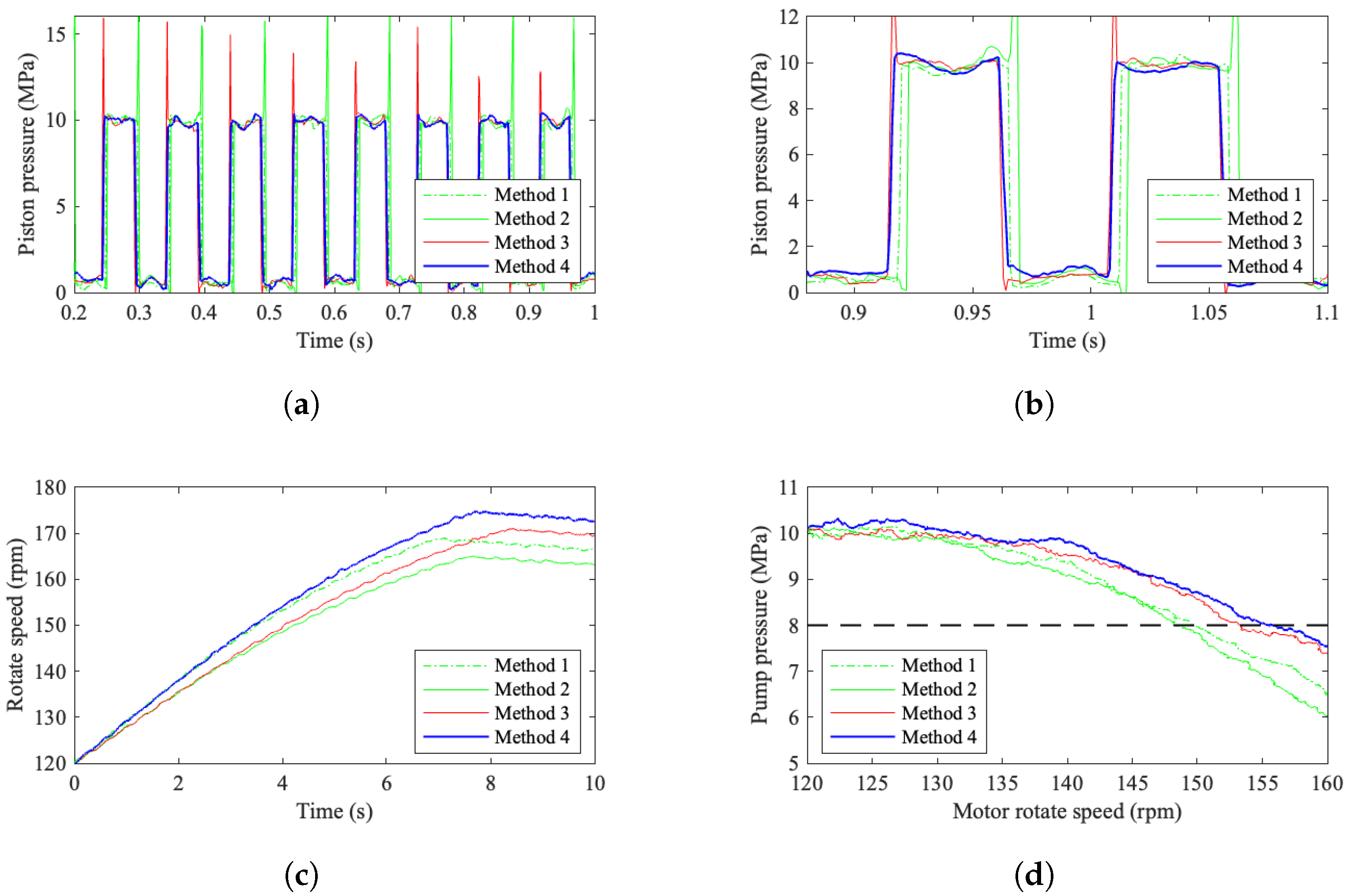
The experimental results are depicted in
Figure 26. This demonstrates that distribution Method 4 attains the highest motor driving efficiency. Furthermore, it exhibits minimal pressure pulsation.
The implementation of a combined sealing structure alongside the replacement of traditional distributor faces with high-speed switching valves can effectively reduce flow losses during motor operation.
Under consistent oil source pressure and flow rate, distribution method 4, which pre-adjusts the piston chamber pressure through phase correction, attains the highest driving torque and the most efficient motor performance. This approach significantly enhances the operational efficiency of digital hydraulic motors, offering substantial practical value for the advancement and widespread adoption of digital hydraulic actuators.
Our preliminary prototype exhibits a 44 Nm/kg specific torque. Design refinements for mass reduction in subsequent iterations are expected to double this ratio to 100 Nm/kg.
8. Conclusions
In conclusion, the digital hydraulic motor emerges as a highly promising innovation for heavy-duty vehicle traction systems, offering substantial improvements over conventional hydraulic technology. Distinguished by superior efficiency, greater power density, and seamless integration, this advanced motor employs a sophisticated flow control mechanism composed of multiple piston groups and precisely regulated flow control valve units. This configuration enables dynamic flow modulation, effectively eliminating the characteristic end-face flow control limitations inherent in traditional hydraulic motors. While current manufacturing costs remain elevated, continued research and development hold significant potential for refining automotive and industrial sectors, thereby enhancing cost efficiency and bolstering the feasibility of widespread adoption in heavy-duty vehicle applications.
Building upon the framework of digitally controlled hydraulic motors, we have performed dynamics modeling. We investigate the intricate interplay between the motor’s geometric and structural parameters and its performance metrics while also assessing how valve distribution influences efficiency. Through an efficiency-focused lens, we meticulously evaluated power losses occurring during digital valve actuation. Leveraging these insights, we elucidated the fundamental principle for mitigating driving torque pulsations and proposed a novel digital torque modulation technique. To substantiate our findings, we conducted rigorous simulation analyses and experimental validations, which conclusively demonstrated both the soundness of the theoretical framework and the operational efficacy of the proposed methodology. The phase-compensation-based discrete flow distribution valve control law developed in this study effectively mitigates pressure pulsation while demonstrating superior drive efficiency.


