Abstract
The contact performance of high-contact-ratio asymmetrical planetary gears is comprehensively evaluated using multiple indicators. The relationship between the indicators and modification parameters is difficult to accurately describe with a single type of surrogate model due to their varying degrees of nonlinearity. This paper proposes an optimization design method for comprehensive modification parameters based on a hybrid surrogate model to improve the optimization accuracy of comprehensive modification. Firstly, a theoretical model of comprehensive modification for high-contact-ratio asymmetrical planetary gears and a dynamically selected hybrid surrogate model are proposed based on different contact performance indicators. Then, the explicit constraints of comprehensive modification and the implicit constraints of non-edge contact are modeled for the modification parameters. Finally, a multi-objective optimization algorithm for the modification parameters based on the hybrid surrogate model is established and validated through experiments and simulations. The results show that the proposed method improves the optimization accuracy and edge contact on the tooth surface is avoided while improving the contact performance, and they provide a reference for efficient and precise optimization of high-contact-ratio asymmetrical planetary gears.
1. Introduction
A high-contact-ratio gear is prone to tooth tip sharpening and breakage. A high-contact-ratio asymmetric gear combines the characteristics of both asymmetric gears and high-contact-ratio gears, effectively overcoming the aforementioned shortcomings. Research on the design and analysis of this new tooth profile gear is being conducted [1,2,3]. Yildirim [4,5,6] pioneered a theoretical study of the meshing of high-contact-ratio gears, laying an important foundation for subsequent research. Mohanty [7] and Rameshkumar [8] revealed the load transfer mechanism under multi-tooth meshing conditions by systematically analyzing the load distribution and contact stress distribution. Sánchez et al. [9] proposed a contact stress calculation method based on the principle of the minimum elastic potential energy, providing a new theoretical tool for strength analysis. Franulovic et al. [10] conducted in-depth research on the impact of manufacturing errors on the meshing performance. Their study showed that tooth pitch errors significantly alter the load distribution coefficient and the accuracy level is a key factor affecting the uniformity of the load distribution. Pleguezuelos [11] established an approximate calculation model for the transmission efficiency of high-contact-ratio gears through theoretical analysis, focusing on the relationship between key parameters such as the transmission ratio, pressure angle, and transmission efficiency. He achieved optimization of the transmission efficiency. To address the issue of scuffing failure in the transmission process in high-contact-ratio gears, Rackov et al. [12,13] proposed a scuffing prediction method that innovatively introduces genetic optimization algorithms into the scuffing calculation model, enabling rapid prediction while maintaining accuracy compared to traditional methods. His study [14] investigated the impact of the gear tooth number and module values on the load capacity in universal helical gear drives, optimizing gear ratio selection for single-stage reducers while balancing the performance and production costs. His analysis highlights trade-offs between the module size, load capacity, and component strength. Mo et al. [15] established an analytical model for the time-varying meshing stiffness of asymmetric helical gears considering the effect of adjacent teeth based on the principle of potential energy. The study found that increasing the pressure angle on the driving side can significantly reduce stiffness fluctuations, especially when the contact ratio is an integer. The study also revealed for the first time that the variation trend of load static transmission errors in asymmetric gears exhibits a unique inverse characteristic compared to the stiffness curve. Karpat [16] proposed an innovative method for calculating the meshing stiffness of asymmetric gears, mainly using the finite element method to calculate the stiffness of a single tooth, providing an important reference to understand involute asymmetric gears. Puneeth et al. [17] revealed the inherent relationship between the dynamic performance and pressure angle by studying the instantaneous contact stress of asymmetric gear pairs under different pressure angles. His study provides a theoretical basis for the optimal selection of the pressure angle. Rajesh et al. [18] established a numerical model for the contact fatigue life of asymmetric helical gears, confirming that asymmetric designs exhibit superior fatigue performance compared to traditional symmetric gears. The characteristics of single-stage planetary and cycloidal reducers have been analyzed [19], with the results showing that planetary gearboxes have an advantage if a lower gear ratio is required. Namboothiri et al. [20] revealed the fracture characteristics of asymmetric gears through three-dimensional fracture analysis, finding that increasing the pressure angle on the driving side significantly enhances the load-bearing capacity of the gear, with the open fracture mode playing a dominant role. Toman et al. [21] were the first to systematically study the influence of the friction coefficient on the performance of asymmetric gears, establishing a stress analysis model that considers meshing friction.
The analysis and optimization of the contact ratio is one of the key issues in the development of high-performance gears. Pedrero et al. [22] analyzed the tooth root stress in high-contact-ratio (HCR) spur gears, where load-induced deflections increased the contact ratio beyond 2, reducing the stress. They compared analytical and finite element models with ISO/AGMA standards, proposing a load-sharing coefficient to correct conservative results while retaining existing geometry factors. Zhu et al. [23] developed a fractal-based TVMS model for super-high-contact-ratio helical gears, incorporating slice-specific contact disparities and axial forces to improve the stiffness accuracy. Huang et al. [24] analyzed the nonlinear dynamics of SHCR helical gears, revealing chaotic behavior under high-speed conditions and the influence of backlash/friction on the system stability.
Regarding analysis and optimization methodologies [25,26,27], a single surrogate model is commonly employed as a fitness function within intelligent algorithms, such as genetic algorithms [28,29,30], to optimize gear meshing and the contact parameters. Tavakoli [31] introduced a generalized method for calculating the static transmission error and load-sharing coefficient, applicable to both external and internal gear meshing across varying contact ratios. This approach centers on minimizing the peak-to-peak static transmission error and selects design variables including the tooth profile modification, modification height, and modification curve parameters, thereby establishing a comprehensive optimization system for gear modification design. Dhafer et al. [32] highlighted the increasing demands on modern gears concerning their load capacity, performance, and noise, noting that trade-offs often exist among metrics such as the transmission error, meshing efficiency, and wear resistance. To address these conflicting requirements, the research team utilized the NSGA-II multi-objective optimization algorithm to optimize the profile modification parameters and validated the method’s feasibility through an engineering case study. Wang et al. [33] developed a rigid–flexible coupled dynamic model for wind turbine gearbox systems, analyzing the influence of tooth surface modification on the system’s dynamic response. Field testing demonstrated that an appropriate modification strategy can significantly improve the gear contact performance, reducing the transmission error fluctuations, vibration, and noise levels. Pleguezuelos et al. [34] proposed a symmetric long modification optimization method based on the assumption of equal time delay intervals, which not only identifies the optimal tip relief curve but also quantitatively relates the modification length to the contact ratio.
The evaluation of the contact performance in high-contact-ratio asymmetric gears involves multiple indicators, such as the peak-to-peak transmission error, maximum tooth surface contact stress, and maximum tooth root bending stress. These indicators exhibit complex and often nonlinear relationships with the modification parameters [35,36,37], which cannot be adequately captured by a single type of surrogate model during optimization. Additionally, the modification parameters are subject to explicit constraint boundary conditions and edge contact limitations to prevent structural failure caused by concentrated contact stress. Therefore, establishing a multi-objective optimization model based on a dynamic hybrid surrogate model and developing a high-precision algorithm capable of accounting for multiple implicit constraints have become essential requirements for the design of high-contact-ratio asymmetric gears.
To deal with these issues, we developed a comprehensive modification theory for high = contact-ratio asymmetric gears and an analysis method based on the hybrid surrogate model. The explicit constraint of comprehensive modification and the implicit constraint of non-edge contact was modeled for the modification parameters. Based on this, a comprehensive modification optimization algorithm based on the hybrid surrogate model was established. Experimental and simulation results verified that the algorithm can effectively avoid edge contact while improving the contact performance.
2. Method for Comprehensive Modification Using Hybrid Surrogate Model for Parameter Analysis
2.1. The Comprehensive Modification of the Tooth Surface Geometry
A high-contact-ratio asymmetric planetary gear is manufactured using an asymmetric gear shaper, as illustrated in Figure 1. The straight segment AB of the rack cutter generates the root arc segment of the gear tooth, the arc segment BC forms the root transition curve, and the segment CD produces the involute profile of the gear tooth.
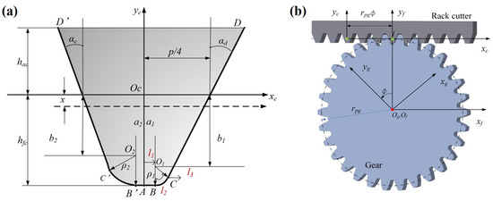
Figure 1.
Schematic diagram of (a) asymmetric rack cutter and (b) meshing of gear and rack cutter.
During gear machining, manufacturing errors are inevitable, leading to tooth profiles that deviate from the ideal theoretical involute. This deviation is further exacerbated by elastic deformation under operating loads. Tooth surface modification is employed to achieve a more favorable contact pattern, thereby enhancing the gear’s load capacity.
Comprehensive modification comprises two components: tooth profile modification and lead crowning, as illustrated in Figure 2. The tooth profile modification is defined by a parabolic function, expressed as follows.
where h is the distance from a point on the standard tooth profile to the origin. is the radius of the tooth tip circle. is the radius at which the modification ends. is the distance from the starting point of tooth tip modification to the origin. is the maximum modification of the tooth tip circle. is the distance from the starting point of tooth root modification to the origin, and is the maximum modification at the involute starting circle.
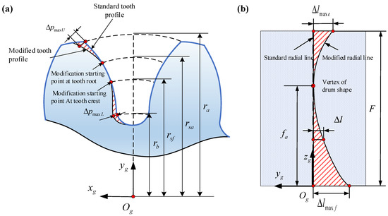
Figure 2.
Schematic diagram of comprehensive modification. (a) Tooth profile modification; (b) tooth direction modification.
The modified tooth profile can be expressed as
where the upper and lower operators correspond to the left and right tooth profiles, respectively. and represent the unit normal vectors of the original tooth profile in the x and y axes, respectively.
The tooth profile modification is expressed by two different parabolas (Figure 2b), and the offset defined by the tooth profile is calculated using
The tooth surface after comprehensive modification is
2.2. Dimensionality Reduction of Modification Parameters Based on SS-ANOVA
Since tooth root modification can compromise the tooth strength, this study focuses exclusively on tooth tip profile modification. The key design variables selected for the tooth tip modification in both the sun gear and planetary gears include the tooth tip modification , the diameter of the starting circle for the modification, ϕs, and the tooth direction drum shape, , of the sun gear, as well as the tooth tip modification Δpp, the diameter of the starting circle for the modification, ϕp, and the tooth direction drum shape, Δlp, of the planetary gear.
A Smooth Spline Analysis of Variance (SS-ANOVA) decomposes a multivariate function into the sum of multiple independent functions, with its extended form being an additive model, as shown in the following equation:
f is expressed as a function of N independent components and is a function of the correlated variables. The component functions are estimated by minimizing the following objective function.
In this case, each component, , adopts the form of a natural cubic spline curve, and each term corresponds to a tuning parameter, .
The contact performance includes three parameters: the maximum contact stress on the tooth surface, ; the maximum bending stress at the tooth root, , and the peak-to-peak transmission error . is defined as follows:
Firstly, the transmission error quantitatively describes the deviation between the ideal position and the actual position of the driven gear:
where is the transmission ratio of the gear, and and are the rotation angles of the driving gear and the driven gear, respectively. and are the initial rotation angles of the driving gear and the driven gear, respectively. As shown in Figure 3, the peak-to-peak transmission error is
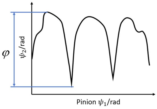
Figure 3.
The transmission error curve.
Obtained through a process based on the SS-ANOVA method, the influence of the modification parameters on the three key performance indicators of the gear transmission (the maximum contact stress on the tooth surface, , the bending stress at the tooth root, , and the peak-to-peak transmission error ,which is introduced in Section 3) is shown in Figure 4.
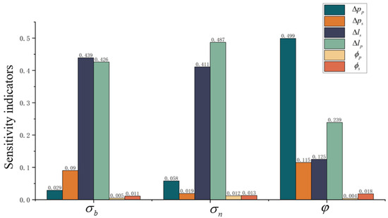
Figure 4.
Sensitivity indicators of the modification parameters.
The results indicate that, in terms of the maximum bending stress at the tooth root and maximum contact stress on the tooth surface, the tooth direction drum shape, , of the sun gear shows the highest sensitivity, while the influence of the diameters of the starting circles for the modification, and , is the weakest. For the peak-to-peak transmission error, the sensitivity ranking is as follows: tooth tip modification of the planetary gear > the tooth direction drum shape of the sun gear > the tooth direction drum shape of the planetary gear . Based on this sensitivity ranking, this study selected the parameters , , and as key optimization variables for further research.
2.3. Accurate Analysis Method Based on Hybrid Surrogate Model
To ensure the robustness of the rapid optimization algorithm, the Uniform Latin Hypercube (ULH) algorithm is adopted. The number of DOE designs is , where is the number of optimization variables and is the number of optimization objective functions. In this optimization model, there are three optimization variables and three objective functions, so the number of DOE designs is 18. The initial sample design scheme is shown in Table 1 (see Section 4.2 for the system parameters and modeling methods).

Table 1.
Samples and their responses.
The three key performance indicators, namely the maximum contact stress on the tooth surface, the maximum bending stress at the tooth root, and the peak-to-peak transmission error, exhibit significant differences in their complexity and linear characteristics. Therefore, this paper adopts a dynamic selection strategy for surrogate models including polynomial response surface models, radial basis functions, Kriging models, and neural network models to establish a surrogate model with the optimal prediction accuracy.
The polynomial response surface model is based on the least squares principle and determines the relationship between the input vector and the output , and its expression is
where n is the number of design variables. , , , , , and are the regression parameters of the response surface, determined using the least squares method.
For radial basis function (rbf) networks, the relationship between the input and output is as follows:
where ci is the center point of the ith radial basis function, and the vector basis function adopts a Gaussian function, i.e., .
Another commonly used surrogate model is the Kriging model, whose expression is
where an the unknown coefficient vector, which is modeled as a Gaussian distribution with a mean of zero.
Lastly, artificial neural networks (ANNs) clearly demonstrate their advantages when dealing with high-dimensional nonlinear problems. However, in the case of small samples, overfitting is prone to occurring.
The accuracy of the surrogate model was evaluated based on the Mean Absolute Error (MAE), Root Mean Squared Error (RMSE), Maximum Absolute Error (MAX), and the Coefficient of Determination (), as follows:
where n is the number of sample points. is the output response of the ith sampling point. is the response estimation value of the surrogate model for the ith sampling point. is the mean of the samples.
3. Constraint Modeling of Comprehensive Modification Parameters
Three key parameters, , , and , are selected as optimizable variables, and the remaining modification parameters are set to fixed values. This study establishes constraint conditions based on tooth surface contact pattern analysis, as follows:
where and define the modification range of the tooth tip for planetary gears; and define the modification range of the tooth direction drum shape for planetary gears; and define the modification range of the tooth direction drum shape for sun gears; and define the position range of the left and right boundaries of the contact print; and and define the position range of the upper boundary of the contact pattern. To avoid edge contact during gear transmission, it is necessary to ensure that there are no boundaries on either side of the tooth surface or across the width of the tooth. Here, and . are the distances from the two boundaries of the print to the widest part of the tooth, and L is the width of the gear. is the distance from the upper boundary of the print to the tooth tip, and H is the height of the tooth surface. The constraints are derived in the following section.
3.1. Explicit Constraints on Modification Parameters
3.1.1. Tooth Profile Modification
In gear modification, a larger modification is not necessarily better. This paper refers to mature and widely used symmetric gear ISO standards [38] as boundary values, providing design intervals to reduce the search space in the optimization process. Meanwhile, the optimization results are not the defined boundary values and are validated through finite element analysis (see Section 4.2.2). The calculation for the modification is as follows:
where b is the tooth width; is the contact ratio of the end face. The other key parameters are defined as follows.
Utilization factor, : An adjustment factor reflecting the load condition, with a value range of 1.0–1.5. For heavy load conditions, it is recommended to adopt the upper-limit value.
Comprehensive meshing stiffness, : . is the stiffness of a single pair of teeth; for gears made of rigid materials, when the unit load N/mm is
When the unit load N/mm is
where in Equation (19) is the theoretical single-pair tooth meshing stiffness. . is the minimum for a pair of flexible gears:
where and are the equivalent teeth numbers of the driving gear and the driven gear, respectively. The coefficients in Equation (20) are listed in Table 2. is the correction coefficient, and ; is the gear blank influence coefficient, and . is the basic tooth profile coefficient, which is determined using . When the large and small gears are machined from gears with different tooth roots, .
Table 2.
Coefficient values in Equation (20) [38].
3.1.2. Tooth Direction Drum Shape Modification
The maximum value of the tooth direction drum shape is determined, and its modification method is shown in Figure 5.
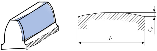
Figure 5.
Schematic diagram of the modification of the tooth direction drum shape.
The drum shape of the gears, , is calculated using
where is the equivalent meshing skewness, using the original skewness of the unmodified gear as a reference value, and a safety factor of 1.5 is introduced to avoid tooth edge contact.
In Equation (21) is the degree of skew of the meshing axis caused by the deformation of the gear body and the supporting shaft system during the transmission of the gear pair. It is calculated using
In the equation, . represents the bearing span, which is the center-to-center distance between two supporting bearings. is the axial distance from the middle plane of the pinion to the midpoint of the bearing span; is the power distribution coefficient. When the transmission system transmits power from a single input source, . If there are multiple inputs, , where k is the percentage of the power contributed by the current input. is the pitch circle diameter. is the equivalent diameter of the gear shaft. is the bearing parameter.
In Equation (21) is the maximum allowable value for the clearance on the sides of the teeth in meshing gear pairs, which is calculated using
is the slope deviation of the helical line, reflecting the effect of the tooth profile modification on the load distribution; is the installation tolerance of the two gear axes at the bearing position, directly affecting the meshing alignment accuracy. is the meshing tooth width.
3.2. Implicit Constraints of Edge Contact
To obtain the precise location of the gear contact pattern, the extracted tooth surface contact stress contour map undergoes data processing. Using the average contact stress of the entire tooth surface as the dividing point, areas where the contact stress exceeds the average are defined as white pixels, while the remaining areas are defined as black pixels. A black-and-white image of the contact print is drawn, as shown in Figure 6.
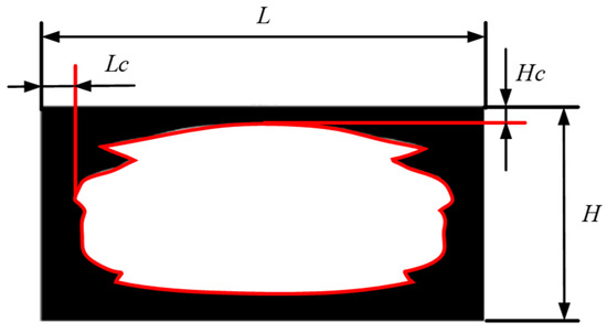
Figure 6.
Contact pattern of the tooth surface.
The positions of the upper () and lower () boundaries of the contact pattern are precisely determined using this method. Here, is the distance from the boundaries on both sides of the print to the widest part of the tooth. is the distance from the upper boundary of the print to the tooth tip. The boundary proportions are defined as and , where L is the tooth width and H is the length of the tooth surface.
Therefore, when , there is no edge contact on either side of the widest part of the tooth; when , there is no edge contact on the tooth tip. Ideally, both and should be greater than zero. In order to maximize the contact area, and should also be as small as possible.
4. Optimization of Comprehensive Modification and Verification Based on Hybrid Surrogate Model
4.1. Multi-Objective Optimization Algorithm for Contact Performance Based on Hybrid Surrogate Model
Multi-objective optimization based on a hybrid surrogate model is solved using the NSGA-II algorithm. In this process, it is necessary to consider the tooth surface constraints. Therefore, a flow chart of the comprehensive modification optimization method based on a hybrid surrogate model proposed in this paper is shown in Figure 7.
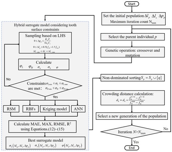
Figure 7.
A flow chart of the proposed optimization algorithm.
Step 1: Under explicit constraints, sample the modification parameters using Uniform Latin Hypercube. Calculate the indentation locations and and contact performances , , and using the finite element model.
Step 2: Calculate the constraints and . Check if the requirements are met to prevent edge contact in the hybrid surrogate model. If not, return to Step 1 to continue sampling. If yes, proceed to Step 3.
Step 3: Establish four surrogate models: an RSM, RBF, Kriging model, and ANN. Calculate the MAE, MAX, RMSE, and R2 indices using Equations (10)–(13), and establish the surrogate models with the best performance: , , and .
Step 4: Initialize the population of modification parameters and the maximum number of iterations.
Step 5: Select a parent individual, p, perform genetic crossover and mutation operations, and obtain the offspring population.
Step 6: Calculate the damage to the population using the hybrid surrogate model from Step 3, and perform non-dominated sorting and crowding degree calculation. Calculate the response of the population using the hybrid surrogate model in Step 3, and perform non-dominated sorting and calculate the crowding distance.
Step 7: Merge the parent and offspring populations. Select the best individuals to form a new generation of the population. Check whether the number of iterations is greater than the maximum number of iterations. If not, return to Step 5; otherwise, the iterations end.
Multi-objective optimization based on a hybrid surrogate model is achieved using this method, and implicit constraints of edge contact are considered in the optimization.
4.2. Case Analysis
In this study, tooth surface optimization was conducted for a high-contact-ratio asymmetrical planetary gear. The parameters are listed in Table 3.
Table 3.
Design parameters of high-contact-ratio asymmetrical planetary gear system.
The high-contact-ratio asymmetrical planetary gear system is shown in Figure 8. The finite element model of the system was based on the parameters in Table 3. The elastic modulus of the gear was 210 MPa, and Poisson’s ratio was 0.3 in the finite element software Abaqus 2018. We selected contact pairs between the tooth surfaces of the sun gear and the planetary gear, as well as two contact pairs between the tooth surfaces of the planetary gear and the inner ring gear. A load was applied at the reference point on the planetary carrier [39], as shown in Figure 9. The input speed was 1500 r/min.
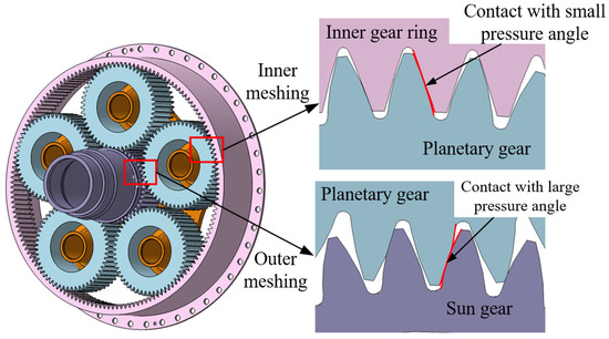
Figure 8.
The high-contact-ratio asymmetrical planetary gear system.
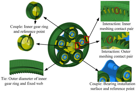
Figure 9.
Finite element model of high-contact-ratio asymmetrical gear system.
The contact performance indicators , , and from the finite element model were obtained for further analysis.
4.2.1. Results and Analysis of Hybrid Surrogate Model
By training the four surrogate models based on the initial sample data, a relationship between the optimization variables and the objective function was obtained, with the corresponding errors as follows.
The response errors of different surrogate models are shown in Table 4. For the maximum contact stress on the tooth surface, σn, the determination coefficient of the radial basis function was the highest, at 0.989804. For the maximum bending stress at the tooth root, the determination coefficient of the radial basis function was the highest, at 0.98849. For the peak-to-peak transmission error φ, the neural network had the highest determination coefficient of 0.995287.
Table 4.
The response errors of different surrogate models: MAE, MAX, RMSE, and R2.
Based on the results obtained from the error analysis, this study adopted a differentiated surrogate model selection strategy for the multi-objective optimization of gear systems. When comparing and analyzing the predictive performance of different models, it was found that the radial basis functions (RBFs) exhibited optimal performance in predicting the maximum contact stress on the tooth surface and maximum bending stress at the tooth root (with a correlation coefficient of 0.98), while the neural network model was optimal in predicting the peak-to-peak transmission error (with a correlation coefficient of 0.99), and both had correlation coefficients very close to one, indicating high model reliability.
4.2.2. Optimization Result Analysis
The modification parameters ∆Pp, ∆lp, and ∆ls were optimized using the proposed method. The remaining modification parameters were set to fixed values as shown in Table 5.
Table 5.
Gear modification parameters in the system.
The design quantity for this experiment was 18, and the number of iterations was set to 50. Therefore, this optimization included 900 sets of calculations. The maximum contact stress on the tooth surface, σn, maximum bending stress at the tooth root, σb, and peak-to-peak transmission error φ are shown in Table 6.
Table 6.
Contact performance response with different modification parameter combinations.
The modification scheme derived from the optimization algorithm proposed in this paper was case C in Table 7. This scheme comprehensively considers the effects of the maximum contact stress on the tooth surface, σn, and maximum bending stress at the tooth root, σb, which improves the performance of the gear transmission system. In contrast, the modification scheme based on traditional empirical formulas was case B. This scheme is relatively simple, primarily relying on existing design experience and formula derivation. However, it has significant limitations in practical applications. The non-modification scheme A incorporated the original contour characteristics of the gear, which provided a reference and comparison for the optimization. The specific modification values and parameter settings for each modification scheme are shown in Table 7.
Table 7.
The parameters of the modification schemes.
The tooth surface contact stress of the gear under rated operating conditions is shown in Figure 10. According to the results, the maximum contact stress on the sun gear tooth surface under the three schemes was 397.5 MPa, 518.8 MPa, and 448.69 MPa, respectively. The maximum contact stress on the planet gear tooth surface was 403.3 MPa, 611.5 MPa, and 493 MPa, respectively.
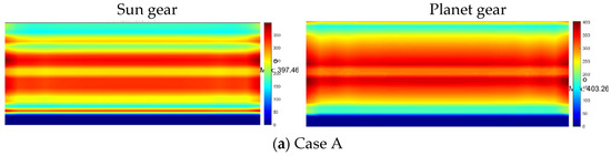
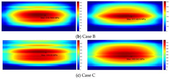
Figure 10.
Contact stress on the tooth surface of the sun gear and planet gear.
Figure 11 shows the contact patterns during gear meshing. It is evident that in modification case A, edge contact occurred on both sides of the tooth root and across the width of the tooth of the sun gear, as well as on both sides of the tooth tip and across the width of the tooth of the planet gear, i.e., . In contrast, the contact in case B and C was mainly concentrated in the middle of the tooth surface, exhibiting a more uniform contact distribution and demonstrating a better load-bearing capacity.
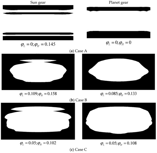
Figure 11.
Contact pattern of the sun gear and planet gear.
From Figure 12, we can see that the maximum bending stresses at the tooth root of the sun gear under the three modification schemes were 157.6 MPa, 227.7 MPa, and 200.3 MPa, respectively. The maximum bending stresses at the tooth root of the planet gear were 150.2 MPa, 214.9 MPa, and 171.9 MPa, respectively.
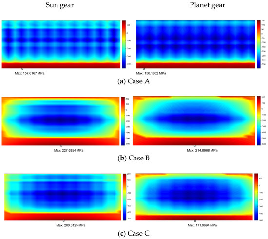
Figure 12.
Bending stress of sun gear and planet gear.
The transmission error curves of the modification schemes are shown in Figure 13, with peak-to-peak values of 3.4 × 10⁻⁵, 4.3 × 10⁻⁵, and 1.9 × 10⁻⁵, respectively.
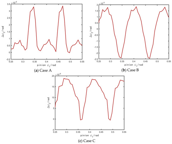
Figure 13.
The transmission error curves of the modification schemes.
From the tooth surface contact pattern, it can be observed that there was significant edge contact in the unmodified case A, although the tooth surface contact stress and tooth root bending stress were relatively small. Under actual operating conditions, the edge contact further intensified due to the assembly errors and load variations, leading to local stress concentration. Although there was no edge contact in case B, it showed higher contact stress and tooth root bending stress as excessive modification reduced the contact area. In contrast, case C performed well in terms of its load-bearing capacity and contact area, with a minimal transmission error. Compared to case B, the maximum contact stress on the sun gear was reduced by about 14%, and the maximum bending stress on the sun gear was reduced by 12%. The maximum contact stress on the planet gear was reduced by 19%, and the maximum bending stress on the planet gear was reduced by 20%; the peak-to-peak transmission error was reduced by 55%. These results indicate that the modification optimization algorithm has good feasibility and improves the load-bearing capacity while optimizing the gear transmission performance.
4.3. Experimental Verification of Optimization Results
To verify the transmission performance of the high-contact-ratio asymmetrical planetary gear after modification optimization, this section compares the tooth surface contact patterns of the physical prototype with the finite element simulation results using the contact pattern analysis method.
4.3.1. Setup of the Experiment
To verify the effectiveness of the modification parameters, a test of the high-contact-ratio asymmetrical planetary gear was conducted, with the parameters listed in Table 3 (the modification parameters are listed in Table 8). The material of the gears was 9310 steel, which was treated through a carburizing process.
Table 8.
Modification parameters of the gears used in the test.
Schematic diagrams of the test platform are shown in Figure 14 and Figure 15. The test platform consisted of a drive motor, a torque loading motor, a test gear system, and a support system. The drive motor provided the power input and transmitted the power to the sun gear input end of the tested planetary gear. The torque loading device applied a controllable load at the output end of the planet carrier to simulate the torque characteristics under actual working conditions. High-stiffness bearing blocks were adopted in the support system to ensure accurate positioning and stable operation of each shaft system.
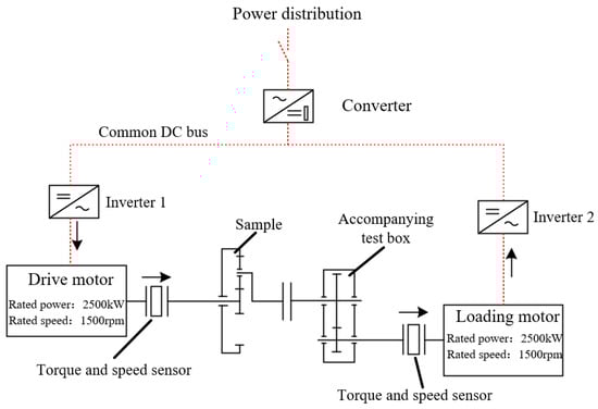
Figure 14.
Schematic diagram of the asymmetrical planetary gear system experimental platform.

Figure 15.
The asymmetrical planetary gear system experimental platform.
A loading contact experiment was conducted, and the experimental steps were as follows.
First, the experimental equipment was initialized, with the operational status of each transmission component verified. A uniform layer of coloring agent was applied to the meshing tooth surfaces of the sun gear, planetary gear, and inner gear ring. Subsequently, the sun gear was mounted onto the input shaft, with its radial runout calibrated before being securely clamped. The planetary gears were then assembled onto the planet carrier, with their axial clearance adjusted accordingly. The inner gear ring was fixed in place, ensuring proper alignment with the theoretical meshing position of the planetary gears.
Following component installation, the axial position of the sun gear was fine-tuned to ensure simultaneous contact between the planetary gears and both the sun gear and the inner gear ring, thereby preliminarily verifying the engagement status. Torque was then applied in stages, beginning with preloading and low-torque operation before gradually increasing to the designated working torque. Throughout the operation, key parameters including the speed, torque, and vibration data were recorded for subsequent analysis.
Upon cessation of the operation, the distribution of the contact patterns on the tooth surfaces of each gear was examined. The area and location of the contact regions were assessed to determine compliance with the design specifications.
4.3.2. Results and Analysis of the Test
The experimental and simulated loading contact areas of the sun gear are shown in Figure 16a and Figure 16c, respectively. The experimental and simulated loading contact areas of the planetary gears are shown in Figure 16b and Figure 16d respectively. By comparison, it can be seen that the simulated contact area obtained from the optimization analysis matched the actual contact area obtained from the experiment, with no edge contact occurring, thus verifying the accuracy of the optimized simulation results.
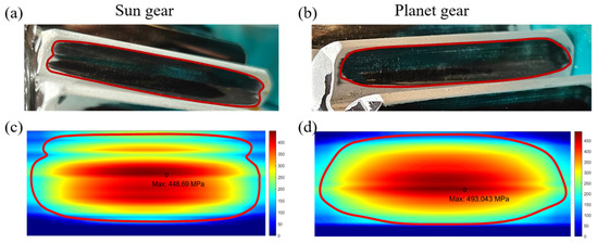
Figure 16.
Comparison of contact pattern of optimized planetary gear system between experiments and simulations. (a,b) experimental results; (c,d) simulation results.
5. Conclusions
In response to the complex nonlinear relationship between the contact performance and comprehensive modification parameters, as well as the implicit constraint requirements of modification methods, this paper establishes a theoretical comprehensive modification model for high-contact-ratio asymmetric gears and proposes a hybrid surrogate model analysis method with dynamic selection. The explicit constraints of comprehensive modification and the implicit constraints of non-edge contact are used for modeling the modification parameters. A comprehensive modification optimization algorithm based on a hybrid surrogate model is proposed to improve the contact performance. The proposed algorithm was applied to the optimization of high-contact-ratio asymmetric planetary gears, and it was found that the proposed algorithm improved the optimization accuracy, accurately avoided edge contact, and reduced the maximum contact stress on the tooth surface and the maximum bending stress on the tooth root compared with the traditional methods.
In the future, this approach can be further expanded to optimize dynamic performance indicators, including by establishing dynamic optimization models. Time-varying loads and speed fluctuations should be considered to construct a more comprehensive multi-objective optimization method.
Author Contributions
Conceptualization, Y.Z.; methodology, Z.T.; software, S.W.; validation, S.W.; formal analysis, Y.Z.; investigation, B.L. and S.W.; resources, J.T.; data curation, S.W.; writing—original draft preparation, B.L.; writing—review and editing, Y.Z.; visualization, S.W.; supervision, Y.Z.; project administration, J.T.; funding acquisition, Y.Z. and B.L. All authors have read and agreed to the published version of the manuscript.
Funding
This research was funded by the National Key R&D Program of China, grant number 2024YFB3410402; the National Natural Science Foundation of China, grant number 52075558; the Industry University Research Cooperation Project of China Aviation Engine Group Co., Ltd., grant number HFZL2024CXY020; the Science and Technology Innovation Program of Hunan Province, grant number 2021RC3012; the Central South University Innovation-Driven Research Program, grant number 2023CXQD050; the Fundamental Research Funds for the Central Universities of Central South University, grant number CX20230255; AECC, grant number KY-1044-2023-0461; and the Project of the State Key Laboratory of Precision Manufacturing for Extreme Service Performance, grant number ZZYJKT2025-07.
Data Availability Statement
The data presented in this study are available on request from the corresponding author.
Conflicts of Interest
The authors declare no conflicts of interest.
References
- Thirumurugan, R.; Deepak, C.; Karthieeban, K. Effect of adjacent teeth load on bending strength of high contact ratio asymmetrical spur gear drive. Int. J. Veh. Struct. Syst. 2017, 9, 32. [Google Scholar] [CrossRef]
- Thirumurugan, R. Study on the quality and tooth root load carrying capacity of the high contact ratio asymmetrical gear tooth machined using WCEDM process. Mater. Manuf. Process. 2020, 35, 1352–1361. [Google Scholar] [CrossRef]
- Liao, F.; Zheng, X.; Huang, J.; Zhu, W. Analysis of Nonlinear Dynamics of a Gear Transmission System Considering Effects of the Extended Tooth Contact. Machines 2025, 13, 155. [Google Scholar] [CrossRef]
- Yıldırım, N. Theoretical and Experimental Research in High Contact Ratio Spur Gearing. Ph.D. Thesis, University of Huddersfield, Huddersfield, UK, 1994. [Google Scholar]
- Yildirim, N. Some guidelines on the use of profile reliefs of high contact ratio spur gears. Proc. Inst. Mech. Eng. Part C J. Mech. Eng. Sci. 2005, 219, 1087–1095. [Google Scholar] [CrossRef]
- Yaldirim, N.; Munro, R.G. A new type of profile relief for high contact ratio spur gears. Proc. Inst. Mech. Eng. Part C J. Mech. Eng. Sci. 1999, 213, 563–568. [Google Scholar] [CrossRef]
- Mohanty, S.C. Tooth load sharing and contact stress analysis of high contact ratio spur gears in mesh. J. Inst. Eng. (India) Part MC Mech. Eng. Div. 2003, 84, 66–70. [Google Scholar]
- Kuzmanović, S.; Vereš, M.; Rackov, M. Generalized Particle Swarm Algorithm for HCR Gearing Geometry Optimization. Sci. Proc. Fac. Mech. Eng. 2012, 20, 36–41. [Google Scholar] [CrossRef]
- Sánchez, M.B.; Pedrero, J.I.; Pleguezuelos, M. Contact stress calculation of high transverse contact ratio spur and helical gear teeth. Mech. Mach. Theory 2013, 64, 93–110. [Google Scholar] [CrossRef]
- Franulovic, M.; Markovic, K.; Vrcan, Z.; Soban, M. Experimental and analytical investigation of the influence of pitch deviations on the loading capacity of HCR spur gears. Mech. Mach. Theory 2017, 117, 96–113. [Google Scholar] [CrossRef]
- Pleguezuelos, M.; Pedrero, J.I.; Sánchez, M.B. Analytical Expressions of the Efficiency of Standard and High Contact Ratio Involute Spur Gears. Math. Probl. Eng. 2013, 2013, 142849. [Google Scholar] [CrossRef]
- Veres, M.; Bosansky, M.; Rackov, M. Possibility of the HCR gearing geometry optimization from pitting damage point of view. Zesz. Nauk. Transp. Politech. Śląska 2012, 76, 125–128. [Google Scholar]
- Rackov, M.; Veres, M.; Kanovic, Ž.; Kuzmanovic, S. HCR Gearing and Optimization of its Geometry. Adv. Mater. Res. 2013, 633, 117–132. [Google Scholar] [CrossRef]
- Rackov, M.; Blagojević, M.; Kuzmanović, S.; Matejić, M.; Knežević, I.; Čavić, M. Influence of the teeth number on the gear module value and load capacity of gear pair in universal helical gear drives. Appl. Eng. Lett. J. Eng. Appl. Sci. 2018, 3, 20–26. [Google Scholar] [CrossRef]
- Mo, S.; Li, Y.; Wang, D.; Hu, X.; Bao, H.; Cen, G.; Huang, Y. An analytical method for the meshing characteristics of asymmetric helical gears with tooth modifications. Mech. Mach. Theory 2023, 185, 105321. [Google Scholar] [CrossRef]
- Karpat, F.; Dogan, O.; Yuce, C.; Ekwaro-Osire, S. An improved numerical method for the mesh stiffness calculation of spur gears with asymmetric teeth on dynamic load analysis. Adv. Mech. Eng. 2017, 9, 1687814017721856. [Google Scholar] [CrossRef]
- Puneeth, M.; Mallesh, G. Dynamic contact behavior of asymmetric spur gear. Mater. Today Proc. 2021, 44, 2019–2027. [Google Scholar] [CrossRef]
- Rajesh, S.; Marimuthu, P.; Babu, P.D.; Venkatraman, R. Contact fatigue life estimation for asymmetric helical gear drives. Int. J. Fatigue 2022, 164, 107155. [Google Scholar] [CrossRef]
- Vasić, M.; Blagojević, M.; Stojić, B.; Dizdar, S.; Ab, G.B.C. Design and performance analysis of an in-wheel hub reducer. Adv. Eng. Lett. 2022, 1, 115–125. [Google Scholar] [CrossRef]
- Namboothiri, N.V.; Marimuthu, P. Investigation of fracture behaviour of asymmetric spur gear. Theor. Appl. Fract. Mech. 2021, 114, 102991. [Google Scholar] [CrossRef]
- Toman, A.A.; Abdullah, M.Q. An analytical approach for predicting the fillet and contact stresses in symmetric and asymmetric spur gears under frictional mesh assumptions. Results Eng. 2024, 23, 102391. [Google Scholar] [CrossRef]
- Pedrero, J.I.; Sánchez, M.B.; Pleguezuelos, M.; Fuentes-Aznar, A. Analysis of the tooth-root stress of external spur gears with high effective contact ratio. Mech. Mach. Theory 2024, 203, 105813. [Google Scholar] [CrossRef]
- Zhu, G.; Huang, K.; Xiong, Y.; Li, A.; Peng, J.; Ding, W. An improved model for time-varying mesh stiffness of super-high-contact-ratio helical gear pair considering contact disparities on differently sliced fractal surfaces. Commun. Nonlinear Sci. Numer. Simul. 2025, 146, 108806. [Google Scholar] [CrossRef]
- Huang, K.; Zhu, G.; Xiong, Y.; Han, G.; Peng, J. Bifurcation and chaos analysis of super-high-contact-ratio gear pair in full speed range considering backlash and friction nonlinearity. Nonlinear Dyn. 2025, 113, 9459–9483. [Google Scholar] [CrossRef]
- Peng, X.; Zhou, J. Optimization design for dynamiccharacteristics of face gear drive with surface-activemodification. Mech. Mach. Theory 2022, 176, 105007. [Google Scholar] [CrossRef]
- Qiu, L.; Hou, X.; Gao, S.; Li, Z.; Zhu, R.; Nguyen, T.V. Vibration optimization of spur gear based on GSA-SA algorithm. PLoS ONE 2023, 18, e0293460. [Google Scholar] [CrossRef]
- Choi, C.; Ahn, H.; Park, Y.-J.; Lee, G.-H.; Kim, S.-C. Influence of gear tooth addendum and dedendum on the helical gear optimization considering mass, efficiency, and transmission error. Mech. Mach. Theory 2021, 166, 104476. [Google Scholar] [CrossRef]
- Li, Z.; Wang, S.; Li, F.; Zou, H.; Liu, L. Research on multiobjective optimization design of meshing performance and dynamic characteristics of herringbone gear pair under 3D modification. J. Mech. Des. 2022, 144, 1103401. [Google Scholar] [CrossRef]
- Ben Younes, E.; Changenet, C.; Bruyère, J.; Rigaud, E.; Perret-Liaudet, J. Multi-objective optimization of gear unit design to improve efficiency and transmission error. Mech. Mach. Theory 2022, 167, 104499. [Google Scholar] [CrossRef]
- Ao, M.; Yu, G.; Wang, L.; Sun, L.; Zhao, J. Optimization synthesis of hybrid six-bar mechanism with non-circular gear constraints. J. Mech. Des. 2023, 145, 064502. [Google Scholar] [CrossRef]
- Tavakoli, M.S.; Houser, D.R. Optimum Profile Modifications for the Minimization of Static Transmission Errors of Spur Gears. J. Mech. Des. 1986, 108, 86–94. [Google Scholar] [CrossRef]
- Dhafer, G.; Jérôme, B.; Philippe, V.; Michel, O.; Mohamed, H. Multi-objective Optimization of Gear Tooth Profile Modifications. In Design and Modeling of Mechanical Systems; Haddar, M., Romdhane, L., Louati, J., Amara, A.B., Eds.; Springer: Berlin/Heidelberg, Germany, 2013; pp. 189–197. [Google Scholar]
- Wang, S.; Zhu, C.; Song, C.; Liu, H.; Tan, J.; Bai, H. Effects of gear modifications on the dynamic characteristics of wind turbine gearbox considering elastic support of the gearbox. J. Mech. Sci. Technol. 2017, 31, 1079–1088. [Google Scholar] [CrossRef]
- Pleguezuelos, M.; Sánchez, M.B.; Pedrero, J.I. Control of transmission error of high contact ratio spur gears with symmetric profile modifications. Mech. Mach. Theory 2020, 149, 103839. [Google Scholar] [CrossRef]
- Rajesh, S.; Marimuthu, P.; Babu, P.D. Optimization of contact stress for the high contact ratio spur gears achieved through novel hob cutter. Forsch. Im Ingenieurwesen 2022, 86, 123–131. [Google Scholar] [CrossRef]
- Nestorovski, B.; Simonovski, P. Analytical and Numerical Contact Stress Analysis of Spur Gears. Sci. Eng. Technol. 2023, 3, 44–49. [Google Scholar] [CrossRef]
- Karthick, M.; Ramakrishna, C.S.; Pugazhenthi, R.; Gudadhe, N.; Baskar, S.; Renu; Kumar, R. Contact stress analysis of xylon coated spur gear using ANSYS workbench. Mater. Today Proc. 2023. [Google Scholar] [CrossRef]
- ISO 6336:2007; Calculation of Load Capacity of Spur and Helical Gears—Part 1: Basic Principles, Introduction and General Influence Factors. International Organization for Standardization: Geneva, Switzerland, 2007.
- Lu, B.; Zhou, Y.; Tang, J.; Wei, S. A GWO-SVR method with dynamic reverse learning for predicting contact performance of an asymmetrical planetary gear system in the case of small-sample database. Mech. Mach. Theory, 2023; under review. [Google Scholar]


Disclaimer/Publisher’s Note: The statements, opinions and data contained in all publications are solely those of the individual author(s) and contributor(s) and not of MDPI and/or the editor(s). MDPI and/or the editor(s) disclaim responsibility for any injury to people or property resulting from any ideas, methods, instructions or products referred to in the content. |
© 2025 by the authors. Licensee MDPI, Basel, Switzerland. This article is an open access article distributed under the terms and conditions of the Creative Commons Attribution (CC BY) license (https://creativecommons.org/licenses/by/4.0/).