Abstract
Electric vehicles offer a promising alternative to traditional internal combustion engine vehicles, mitigating air and noise pollution while reducing reliance on petroleum resources. However, the widespread adoption of electric vehicles faces several challenges, including high upfront costs, limited driving range, and the availability of charging infrastructure. The shift toward electric vehicle motors that do not rely on rare-earth elements is an important and massive engineering undertaking. Permanent magnet synchronous motors, which use copper windings instead of permanent magnets to generate the excitation field, offer an alternative approach to reducing rare-earth material usage, with research focusing on optimizing their design and control for electric vehicle applications. Induction motors are being reconsidered for the majority of electric vehicle models due to their robust design, established manufacturing infrastructure, and absence of rare-earth magnets, offering a viable alternative with ongoing research focused on improving their efficiency and power density. New electric vehicle (EV) motors using rotors outfitted with electromagnets (i.e., wire coils) are perhaps the most promising near-term solution for producing powerful motors without REEs altogether. This paper presents an overview of electric vehicles with the possible inclusion of rare-earth-free elements.
1. Introduction
The automotive industry is experiencing a substantial change as more people worry about the environment and seek more environmentally friendly ways to get around. Electric vehicles are a good option for traditional internal combustion engine vehicles because they reduce air and noise pollution and reliance on petroleum resources [1,2]. But there are a number of problems that need to be solved before electric cars can be widely used. These include high initial costs, a short driving range, and a lack of charging stations [3,4,5]. The electric motor is a very important part of electric vehicle technology because it changes electrical energy into mechanical energy to move a vehicle [6]. The choice of an electric motor has a big effect on how well, how efficiently, and how much the electric vehicle costs [7]. To reduce their dependence on oil and the harm inflicted on the environment, many countries are speeding up the production of electric cars [8]. The electric motor is a very important part of how well an electric vehicle works and how it is made [9]. In the last few years, more and more people have been interested in making electric vehicle motors that do not need rare-earth elements. Since they are efficient, powerful, and small, permanent magnetized synchronous motors are often used in electric vehicles. Most of these engines use rare-earth magnets such as neodymium and dysprosium to create strong magnetic fields [10]. However, the use of rare-earth elements leads to concerns about how they affect the environment and the supply chain [11]. A few countries mine and process the rarest elements of the Earth, creating geopolitical risks and price fluctuations [12]. The extraction and processing of rare-earth elements can also harm the environment by destroying habitats, polluting water, and producing radioactive waste. Therefore, researchers and manufacturers are actively looking for other motor designs that use little or no rare-earth elements [13]. One of the advantages of using motors without rare-earth magnets is that parts do not have to be sourced from China [14]. There is much evidence that electric vehicles are better for the environment than internal combustion engines. Studies have shown that they are much better at reducing greenhouse gas emissions, noise pollution, and local air pollutants [15,16]. Electric vehicles use electric motors to convert electricity into mechanical movement, which is what distinguishes them from normal cars [17]. Electric motors have inherent advantages, such as high efficiency, rapid torque response, and the ability to use regenerative brakes [18]. But it is difficult to manufacture electric cars because they have to handle high power levels and function well in a wide range of speeds and conditions [19]. Most modern vehicles have been using internal combustion engines for about a century, while electric power is used in trains and small vehicles [20]. Meanwhile, improving battery technology and increasing environmental concerns have made electric vehicles more functional, and more research and development opportunities have resulted. Currently, the permanent magnet synchronous motors used in electric vehicles can be replaced with several different types of motors. Induction motors, synchronous reluctance motors, and wound rotor motors have good performance attributes without dependence on rare-earth magnets [21]. Each type of motor has its own advantages and disadvantages when it comes to efficiency, torque density, and control difficulty. Induction motors are well-known, well-built, and easy to manufacture. They are good at a wide range of speeds but are usually not as efficient or powerful as permanent magnet synchronous motors. Synchronous reluctance motors are another good choice because they have a simple and strong rotor design, as well as high efficiency and torque density. But synchronous reluctance motors need advanced control strategies in order to work at their best. The rotation of the rotor of a synchronous motor creates a magnetic field. This allows one to change the field resistance and make the motor more efficient at high speeds. Such a motor is very efficient and delivers significant power, but it requires a more complex rotor design and control system. Direct torque control is a simple, strong, and very efficient way of controlling induction motors, so it receives much attention as a way to control induction motors under changing conditions [22]. The current use of rare-earth materials in electric cars raises significant concerns related to supply chains, environmental impact, and geopolitics. The development of innovative automotive technology that reduces the requirement for rare-earth elements or eliminates them is essential for the long-term success and safety of the electric vehicle industry. New materials, improved control systems, and new motor designs are needed to operate electric cars without rare-earth magnets. The overall aim of this study is to find the most efficient electric motor possible without the use of rare-earth elements. We can use this information to strengthen future electric car powertrain plans. Synchronous reluctance engines are better suited for electric cars compared to permanent magnet motors. They are not only functional, user-friendly, and durable but also attractive [23]. Because they do not use rare-earth magnets, synchronized resistance motors are not harmful to the environment or supply chain [24]. The combination of static particle magnetic fields and rotor resistance allows these motors to generate torque. Several obstructions to flow are present in the rotor. Due to their low cost, easy manufacturing, and improved recycling, synchronized resistors do not require rare-earth magnets. When designing a synchronous reluctance motor, it is necessary to carefully adjust the rotor’s geometry to obtain the optimal salinity ratio (i.e., the direct and square conductivity ratio) [21]. A high torque density and power factor can only be achieved with a high-salinity synchronous resistor motor. Computer methods such as finite element analysis are used to improve the design of electric motor rotors [25].
Synchronous reluctance motors are more efficient than permanent magnet motors, especially when finely tuned to certain operating conditions. Synchronous reluctance motors also have a wider range of constant power speeds than inductive motors. They are therefore suitable for electric vehicles that need to operate at low and high speeds [26]. Compared to other types of motors, such as inductive motors and permanent magnetic synchronous motors, the efficiency, cost-effectiveness, and environmental benefits of synchronous reluctance motors have proven them to be a good choice [27]. Adding permanent magnets to a synchronous reluctance motor’s rotor structure makes performance even better. Permanent magnet-assisted synchronous reluctance motors combine the best features of both types of motors to make them more efficient, increasing torque density [28]. When permanent magnets are added to the rotor structure, the air gap’s flow density increases, increasing torque and improving the power factor. However, these motors use much less permanent magnetic material than permanent magnetic synchronous motors, i.e., they do not require many rare-earth elements. In the design of synchronous resistors powered by permanent magnets, it is important to consider the balance between costs, efficiency, and torque density. Finite element analysis and other optimization methods are often used to determine the best number and location of permanent magnets on the rotor. In addition, PMSMs are more efficient under all conditions than AC synchronous motors. In addition, PMSM traction systems use less energy when in motion and produce more energy during braking than asynchronous systems [29]. Improved finite control settings and model predictive current control strategies can improve the performance of IPMSM drivers when model parameters do not match. Switched reluctance motors are a promising alternative for powering electric vehicles instead of rare-earth magnet motors. They are robust, have a simple construction, and their rotors do not contain windings or magnets, reducing reliance on rare-earth materials [30]. This design makes them naturally resistant to defects and cheap to manufacture. The principle of variable resistance is the mechanism required for switched resistance motors to work. The torque is derived from the tendency of the rotor to align with the magnetic field generated by the shaft’s rotation. Switched resistance motors do not use permanent magnets, so they do not need rare-earth elements. This solves supply chain and environmental problems. While the torque density of a switched reluctance motor is lower than that of a permanent magnet motor, new motor designs and control technologies have improved it greatly. These improvements include better magnetic materials, improved rotors and stator shapes, and more advanced control algorithms. A switched resistance motor is very powerful because it can operate at high frequencies and is good for high-speed applications.
The control of a switched reluctance motor may be more difficult than the control of a permanent magnet motor. To achieve the best performance, one must be very careful in measuring the current flowing through the stator curve. However, the creation of advanced control methods such as torque vector control and direct torque control allowed the operation of modified resistance engines with greater accuracy and efficiency. Electric vehicles can use self-powered resistance-to-use motor drives [31]. Testing reluctance switching motors in electric vehicles shows that they can deliver competitive torque and power levels without the use of a rare-earth magnet. Moreover, studies indicate that reluctance motors used in electric vehicles generally have lower costs, primarily due to their simple rotor design and the absence of rare-earth materials [32]. However, innovative control strategies are being developed to improve their use [33]. The use of the flow reverse principle in axial flow magnet machines has been studied to address challenges associated with the use of rare-earth elements [34]. Multiphase permanent magnet motors have also been used to ensure sufficient torque [35]. Induction motors are established technologies that can also be used to power electric vehicles without the use of magnetic fields. Induction motors are strong, reliable, and cost-effective, so they are used in many industrial environments. Induction motors are cheaper than permanent magnet motors in electric cars, especially when performance is not the most important factor. Induction motors are less efficient than permanent magnet motors, especially when the load is light. However, new designs and control methods have made them more efficient. For maximum torque and efficiency, different speed control methods, such as direct torque control, sensorless vector control, and field-oriented control, are used [36]. Another overview focused on improving the effectiveness of permanent magnet synchronous motors by applying sophisticated control algorithms and parameter estimation methods [37]. The analysis focuses on the indirect vector control method for determining flow and torque components based on the machine parameters of induction motors [38]. In addition, a simple way to keep the flow of the motor drives constant is to use a constant voltage/frequency ratio. However, this method can cause poor torque and flow dynamic performance [39]. Field-oriented control and direct torque control are two modern control methods that allow one to control the torque and flow of inductive motors with precision. This makes it easier and more efficient to work with electric cars [40]. Induction motors can be improved by changing the design of the motors and using better materials. Axial current motors can also produce a large amount of torque at short axial lengths and are a good choice for hybrid vehicles [41]. Electric induction motors are important because they are simple, low-cost, and easy to control [42]. To ensure speed and torque levels, modified PI and V/F scale controllers are used [43]. Inductive motor drives are easy to construct, robust, and safe, and they only require little maintenance. These motors can also change speeds, but due to new control systems, the cost of making variable-speed drives has increased. Three-phase induction machines are considered to be the best option for industrial and AC drives because they are reliable, cheap, powerful, and easy to use and maintain. Induction motors are widely used in the industry, as they have well-known methods for controlling motor speeds and torques [44,45].
Different control methods can improve the operation of induction motors. To deal with nonlinearity, a fuzzy logic controller is used [46]. Compared to proportional integration controllers [47], fractional order controllers can make AC drives work better. Indirect vector control is a common method of estimating the flow angle of the same circuit model using rotor speed, static current, and voltage measurements. However, standard induction motors have some problems, such as low efficiency and power factors. A double-feed induction generator can solve these problems. Indirect field control is a simple and conventional control method [48,49]. In recent years, sensorless control of inductive motor driving has become more and more popular due to its low cost, reliability, and small size. The scale control method is easy to use and configure, while the vector control method is better able to control torque and react quickly to changes [50]. Field control and direct torque control are two advanced control methods that allow one to control torque and flow very precisely in inductive motors. This makes them work better in electric vehicles.
Advanced control methods, such as sliding mode control, can be used to make inductive motor drives work better and more reliably. To mitigate this phenomenon, dynamic sliding mode control was developed using secondary PID sliding surfaces [51]. Furthermore, the current control of electrical machines has a major impact on how machines work, such as the energy they use and the torque they generate. In order to improve efficiency and make systems more reliable, new estimates and advanced control methods such as predictive modeling control, adaptive control algorithms, field-based control, and direct torque control are being developed. This enables us to understand how IM works in a nonlinear manner and makes feedback more reliable and effective. The effectiveness of estimating the rotor’s position depends on the control strategies used, including field control or direct torque control. If one tries to find a constant torque point, tracking the rotation flow without a separate control loop is very helpful. This ensures that the torque per amp is as high as possible.
Before diving into the aspects of rare-earth-free EVs, a brief insight into the fuel cell EV is also provided. Fuel cell electric vehicles are a good choice for sustainable transportation because they do not pollute the air and use energy efficiently. Electrochemistry is used by fuel cell vehicles to turn hydrogen’s chemical energy into electricity, which runs an electric motor. This method cuts down on air pollution and greenhouse gases by eliminating burning. In a fuel cell stack, fuel cell vehicles break down hydrogen molecules into protons and electrons. Protons pass through a proton exchange membrane, and electrons pass through an external circuit, resulting in electricity. An electric motor powers the car. Fuel cells are a good source of energy for both moving and stationary objects. Fuel cells are more appealing because they produce electricity in a clean and efficient way. Current research is exploring materials and methods to develop fuel cells that work better and make fuel cell components easier to use. To make fuel cells more widely used, researchers are working on making them more efficient, cheaper, and longer-lasting. Electric motors are needed to give fuel cell cars the torque and power they need to move vehicles. There are many types of motors that electric vehicles use, and each has its own pros and cons. Electric cars use induction motors that are strong and dependable. Permanent magnet synchronous motors are better for applications that need high performance because they are more efficient and have a higher power density [52]. Another type is the switching reluctance motor, which is simple and can handle mistakes. The best motor technology for a vehicle to use depends on how well it works, how much it costs, and how efficient it is. Electric cars are a better choice than gas-powered cars because gas-powered cars are less efficient, pollute the air, and use energy sources that cannot be replaced [53]. Electric cars have a short range, take a long time to charge, and do not have much charging infrastructure. Many countries are switching to fuel cells because the technology is improving quickly. There are both problems and opportunities that come with putting fuel cells and electric motors together in fuel cell cars. Electric motors in FCEVs run on electricity from fuel cell stacks. Motor performance affects how far and how efficiently a vehicle can travel. To ensure that fuel-cell-motor control techniques work well and vehicles run smoothly, they need to be improved. Fuel cell technology is used in industrial trucks all over the world. Fuel cell technology has a lot of economic and environmental benefits over lead–acid batteries. For example, it does not require changing batteries, it makes vehicles work better, and it lowers carbon emissions. Fuel cell vehicles’ performance and efficiency are improving due to motor technology advances, like high-efficiency permanent magnet motors and motor control algorithms. Brushless DC motors are popular due to their efficiency, durability, and speed range. They require little maintenance because they work without brushes. The motor affects how well an electric car works, so it is important to choose an appropriate motor. Performance criteria, financial constraints, and efficiency targets influence selection. Table 1 brings out a comparison between battery electric vehicles and fuel cell electric vehicles and Table 2 manifests the motor types employed in Fuel Cell Electric Vehicles. This paper provides an overview of the potentially influential parts of electric cars and rare-earth elements.

Table 1.
Comparison between battery electric vehicles (BEVs) and fuel cell electric vehicles (FCEVs).
Table 2.
Motor types employed in FCEV.
2. Rare-Earth-Element-Based Motors and Global Scenarios
Permanent magnet synchronous motors offer high efficiency, high power density, and excellent torque control, making them attractive for electric vehicle propulsion. These motors are widely used in electric vehicles due to their high efficiency and power density; however, their reliance on rare-earth magnets poses challenges related to cost, supply chain security, and environmental impact [54]. The development of electric vehicles is propelled by advancements in control systems, including torque vectoring, which enhances vehicle stability through precise torque distribution to individual wheels [55]. Electric vehicles with multiple actuators have undergone extensive research, leading to advancements in fault-tolerant control, coordinated chassis control, integrated vehicle-following control, energy management strategies, battery state-of-charge estimation, and driving modes [56]. Model predictive torque control with duty cycle control is used because of its low torque ripple and good steady-state performance [37]. Additionally, model predictive control enhances dynamic response and disturbance rejection capabilities in axial-field switched-flux permanent magnet machine drive systems, ensuring precise torque and speed regulation [57].
In the automotive industry, traction control systems play a crucial role in ensuring vehicle stability and preventing wheel slip, especially during acceleration and cornering. A stability-guaranteed and energy-conserving torque distribution strategy is proposed for vehicles using an innovative master–slave control framework to address these issues. To deal with the issue of single torque distribution targets, a multi-target coordinated control approach that considers both stability and economy is proposed, which includes a coordination decision controller, a high-level motion controller, and a low-level allocation controller [58]. The high-level motion controller consists of a bicycle model with two degrees of freedom, a speed tracking controller, a stability controller, and an economic controller to calculate the desired direct yaw moment of four in-wheel motors. Advanced control strategies, such as hierarchical control, can effectively manage the complexity and over-actuation challenges associated with independently actuated electric vehicles, enhancing vehicle stability and driving performance [59]. Wheel torque control strategies should meet the demand for improved vehicle steering maneuverability and energy savings while balancing the slip ratio of the four wheels to prevent excessive wheel spin [60]. The types of rare-earth elements (REEs) in electric vehicle motors and their application and design in different types of motors are manifested in Figure 1 and Figure 2.
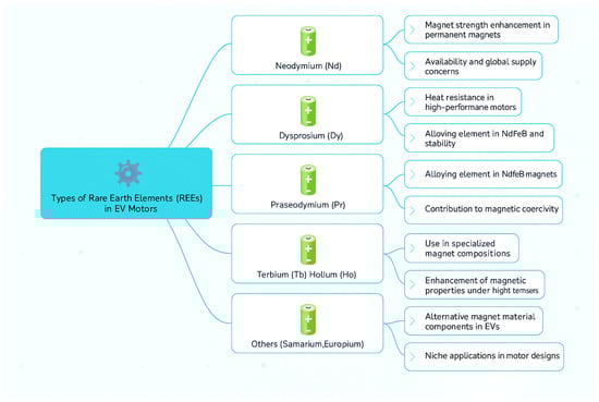
Figure 1.
Types of rare-earth elements (REEs) in electric vehicle motors.
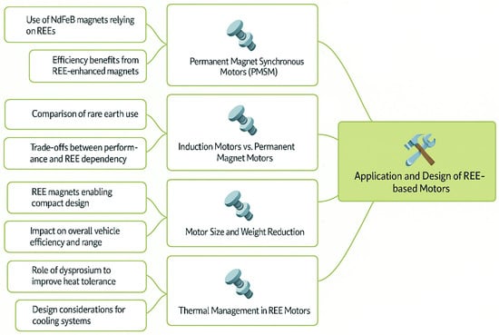
Figure 2.
Application and design of REE-based motors.
China is the world’s leading producer of “Rare Earth Element” materials, accounting for more than 90% of total production. If the supply of rare-earth elements is limited, the growth of renewable energy and the automotive industry will slow down considerably. China cut half of Germany’s supply of rare-earth elements (REEs) in the last quarter. They are used for phones, digital cameras, computer hard drives, fluorescent lights, LED lights, flat screen TVs, computer monitors, and electronic displays. However, most of their business still comes from renewable energies such as wind turbines, solar cells, energy storage batteries, missile guidance systems, and satellite communications. When the supply of REE is limited, the most affected parts of electric vehicles are energy storage devices and electric motors. A flow diagram is shown in Figure 3.
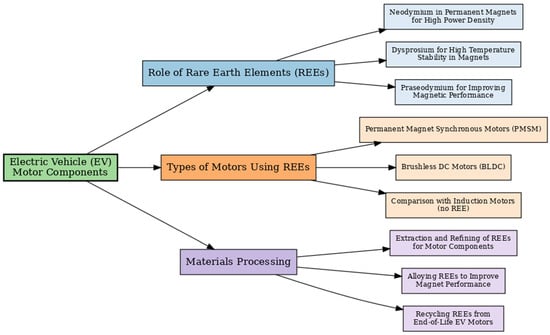
Figure 3.
Role of REE elements in EV motors.
Nickel metal-hydroxide batteries (NiMHs) are used in hybrid electric vehicles that require rare-earth elements (REEs) to store energy. Lanthane is used as an anode of nickel metal-hydroxide batteries (NMHs). A typical hybrid EV needs about 10 to 15 kg of lanthane per unit. Redox flow batteries are another important use of rare-earth elements. For example, zinc cement redox flow batteries use cerium as part of a high-voltage energy storage grid-sized battery, and electric vehicle engines work better when they use neodymium magnets and produce more torque. Many electric vehicle motors use neodymium–iron–boron magnets (NdFeBs). These magnets are better because they contain small amounts of neodymium, Dy, terbium (Tb), and Samarium (Sm). Scientists and engineers from universities and companies are working hard to develop new magnets and other technologies that do not use rare-earth elements (REEs). Tetrataenite and manganese bismuth (MnBi) magnets are new types of magnets that aim to reduce or eliminate the need for rare-earth elements in electric vehicles. An example is Toyota’s fourth-generation Prius engine. The global distribution of rare-earth elements are shown in Figure 4.
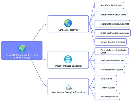
Figure 4.
Global distribution of rare-earth elements.
REEs or rare-earth elements are very important for many modern technologies because of their special characteristics. Iron, cobalt, nickel, sodium, dysprosium, and terbium form crystals that are very magnetic and hard to demagnetize. The maximum energy produced by mega-Gauss–Oersted is used to measure these important magnetic properties. Neodymium–iron–boron permanent magnets are the strongest and most useful in business. They produce energy products from 30 to 55 MGOe, and permanent magnet electric motors are smaller, lighter, and more efficient because they use strong magnets. Consequently, magnets of neodymium–iron–boron are used in all the best electric vehicles. If made properly, other magnet motors can be better than permanent magnet motors using rare-earth elements. Learning a little about electric motors can help one understand them better. Electric motors can be classified into two general categories: synchronous and inductive. Most modern electric vehicles use synchronous motors that are embedded in permanent magnets in rotors. Induction motors do not require rare-earth elements because they are dependent solely on electrical magnets. Several research and development initiatives worldwide are aimed at improving the induction motor, but in most electric vehicles, they are not currently used due to their lower performance compared to permanent magnetic motors. The “synchronous” component of the “synchronous motor” means that the motor’s rotor rotates in lockstep with the magnetic field that changes the stator (the constant part). Permanent magnets are embedded in the circular pattern of the entire rotor. Another component with a circular layout is a stator that uses a pulse to create a rotating magnetic field via an electrical magnet. This method generates torque and rotation by repeatedly attracting and reversing magnets in rotating and stationary gears. Even synchronous motors are divided into various types. One type is the synchronous reluctance motor, while the other is the permanent synchronous motor of a surface mount. The first category uses permanent magnets attached to the outer side of the rotor; torque is generated when various elements of the rotor and the rotor itself experience attractive or repulsive forces. However, permanent magnets are completely unnecessary for the rotation of synchronous reluctance motors. The rotation of the motor is caused by magnetic resistance, which is the resistance of the material to the magnetic flow. Ferritic magnetic materials are resistant to low power and aligned with strong magnetic fields. Resistance engines rotate ferromagnetic rotors using this phenomenon (some reluctance engines use permanent magnets to further assist rotation). Motors are permanently controlled by magnets and are said to depend primarily on the magnetic field interactions of static rotation and rotating rotors. Conversely, permanent magnet-assisted engines are driven via torque based on resistance changes. In order to achieve high performance in low-resolution magnetic rare-earth engines (REEs), engineers combine the torque generated by permanent magnetic attraction and displacement with the torque generated by magnetic lines flowing along the path of least resistance. If a non-REE magnet is used instead of an REE magnet, the motor’s performance suffers. However, advances in motor design, production, and materials will be sufficient to compensate or eliminate these performance differences. Currently, interior magnetized permanent motors are the most popular designs, which combine both types of torque. The motor increases resistance torque using permanent magnets embedded in the rotating wheel. This rotor design is used by many manufacturers of commercial electric vehicles, such as Toyota, Tesla, and General Motors. The design of the Toyota Prius engine shows the efficiency of this methodology. Over the past 13 years, the magnet size of these engines has declined dramatically from 1.2 kg in 2004 to about 0.5 kg in 2017. Similarly, the Chevrolet Bolt’s motors generally use less magnetic material than their predecessor, the Chevrolet Spark.
3. Environmental and Societal Considerations
To combat climate change, reducing reliance on fossil fuels is essential. As illustrated in Figure 5, environmental and social factors must be considered. Transitioning from internal combustion engines to electric drivetrains—aligned with the principle of ‘electrifying transportation’—is key. This shift will increase demand for electric traction motors that depend on rare-earth elements.
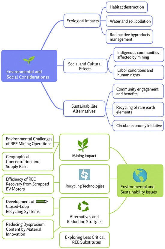
Figure 5.
Environmental and social considerations.
Moreover, the mining and processing of rare-earth elements significantly contribute to environmental pollution. Non-Chinese automakers are vulnerable due to their reliance on these materials, as China currently dominates rare-earth processing, accounting for over 90% of global production. In response, manufacturers are exploring alternatives, leading to the development and testing of new electric vehicle (EV) motors that do not depend on rare-earth elements. To address supply chain risks, governments and companies in industrialized nations are collaborating on solutions. For example, U.S. national laboratories have successfully developed permanent magnets and motors free of rare-earth content. Niron Magnetics, in partnership with Stellantis and General Motors, manufactures electric motors using such magnets—an initiative announced in November. In March, Tesla also revealed that its upcoming “Next Drive Unit” will not rely on “single-land elements,” yet it will still use permanent magnets. In Europe, the “Passenger” partnership includes 20 universities and companies working on similar goals—creating permanent magnets for EVs that eliminate rare-earth elements. In the U.S., the Oak Ridge National Laboratory (ORNL) has spent nearly a decade advancing traction motor technology and is considered a leading center for electric vehicle research. Through the U.S. DRIVE (Driving Research and Innovation for Vehicle Efficiency and Energy Sustainability) consortium, ORNL collaborates with Ames Laboratory, University of Wisconsin–Madison, the National Renewable Energy Laboratory (NREL), Illinois Tech, Purdue University, and Sandia National Laboratories. Engineers are increasingly aware of alternatives to rare-earth materials in motor design and are pursuing research into new magnetic materials and motor architectures. This includes redesigning motors for optimal performance without rare-earth magnets. While substituting rare-earth with non-rare-earth magnets typically reduces performance, future advancements in materials, design, and manufacturing are expected to close that gap. Promising candidates include modern versions of permanent magnet synchronous motors that do not require rare-earth elements.
4. Maximizing the Efficacy of Rare-Earth-Free Permanent Magnets
Rare-earth magnets may not be needed for wound rotor synchronization, switching resistance, or induction motors. Many people are thinking about purchasing these cars instead of electric cars. Using different motors could reduce the use of rare-earth elements. Reluctant switching motors are low in cost, easy to manufacture, and are fault-tolerant. However, they have a larger torque spread and lower torque density than permanent magnet motors. Electric vehicles often use induction motors because they are durable, reliable, and do not require rare-earth magnets. The ability to control sudden torque variations enhances vehicle stability and reduces energy consumption [3]. Advanced control strategies—such as fuzzy logic control—enable dynamic prioritization of control objectives through a multi-objective online optimization function, improving both stability and economic performance in various driving conditions [61].In place of permanent magnets, synchronous reluctance motors use copper windings to generate magnetic fields. Researchers are studying how these motors are built and controlled to reduce reliance on rare-earth materials. Another alternative is the switched reluctance motor, which generates torque through magnetic reluctance. While it is more cost-effective and suitable for electric vehicles, it tends to produce more noise and torque ripple compared to permanent magnet motors. Additionally, certain synchronous motors operate using capacitive power transmission without the need for permanent magnets, even when damaged, and have demonstrated good performance [62]. As part of the push for rare-earth-free solutions, Figure 3 presents sustainable material alternatives.
The characteristics of sustainable materials in the form of EVs without special rare earths are shown in Figure 6. There are two ways to eliminate rare-earth elements. When selecting the motor, choose a permanent magnet that does not contain rare-earth elements (REEs) or switch to an electromagnet motor. One needs to consider two other characteristics of the permanent magnet, resuscitation and coerciveness, to determine whether a permanent magnet containing a rare-earth element is suitable for use in a powerful torque motor. The maximum energy product is the standard for assessing the strength of various permanent magnet materials. The performance of the permanent magnet material of the motor is mainly determined by the following three parameters: maximum energy product, retention, and coercion. When the magnetic field that magnetizes permanent magnets is removed, the remaining magnetic intensity of the magnets (measured by force density) is called remanence. The presence of remanence is essential to the function of permanent magnets. The torque-induced magnetic attraction and resistance forces increase with an increase in the remanence of the material. The coercion of a permanent magnet indicates how well it can withstand demagnetization. A greater coercivity number indicates that demagnetization by external magnetic fields is more difficult. The ideal permanent magnets for electric vehicle traction motors, such as nickel–iron–boron, would have high resistance and persistence and maximum energy. All these features are not present in permanent magnets with REEs. A drop in torque output and a higher risk of demagnetization could be anticipated if we swap out neodymium–iron–boron magnets for, for example, ferrite magnets in a motor. Motorists can reduce the differences by including resistance and permanent magnets in their designs. In order to obtain the same performance as a rare-earth magnet motor, ferrite magnet motors will need to be much heavier, perhaps one-third or more, depending on the well-optimized design. Concentrating the flow of ferrite magnets to the maximum possible extent is one way to obtain the best performance from them. This situation is similar to the speed with which water flows through narrow holes, such as funnels. A spoke magnet motor, known by researchers, is about 30% heavier than a similar motor manufactured by an REE magnet. Unfortunately, the bad news does not stop here; the spoke motor presents unique mechanical problems and is difficult to produce. Some designers have considered alternative non-REE magnets; one such material is the aluminum–nickel–cobalt alloy, often used for refrigerator doors. Despite their high durability, alnico magnets are easily demagnetized due to their low coercivity. Some researchers have discovered and developed variable flow memory motors to solve this problem. These engines use magnetic components that generate current and torque to effectively prevent the magnet from demagnetizing during operation. In addition, scientists at the Ames Institute have shown that alnico magnets can retain their high resistance and even increase their coercion. In the performance of electric motors, three parameters (maximum energy product, durability, and force) refer to the permanent magnet material. Iron nitride (FeN) is a new permanent magnet material that has attracted considerable interest. This magnet, manufactured by Niron Magnetics, has high resistance—essentially the same as REE magnets—but low coercivity—about a fifth of a similar neodymium boron magnet—just like alnico. New rotor designs similar to those of previous alnico engines are required for FeN magnets because they have fundamentally different characteristics. General Motors is one of Niron’s automotive suppliers that is currently developing similar ideas: for example, the engine manufactured by the ZF Group. Last year, the company announced that it had manufactured a synchronous motor, which was installed on a rotor with electromagnets and powered by an inductive system integrated into the machine’s shaft. The company’s official stated that 220 kW motors compete with NdFeB permanent magnet motors used in electric vehicles in terms of power density and efficiency. Furthermore, new materials have the potential to improve the motors of REE and non-REE magnets. For example, the exceptional magnetic performance of high-silicon steel makes it an attractive rotor construction material with the ability to increase the magnetic efficiency of non-rare-earth-element motors. At the same time, using ultraconductive copper lines or high-conducting copper alloys can increase performance and reduce electrical losses. For example, some motors may have a half-decay capacity if copper conductivity is doubled. The difference in performance between a motor containing a rare-earth element (REE) and a motor containing a non-rare-earth element (REE) can be significantly reduced by consciously incorporating these materials. Another example of a cutting-edge material that changes the game is GE Aerospace’s two-phase magnetic material, which can be locally magnetized at extreme power or unmagnetized. GE Aerospace’s team has shown that almost all magnetic leakage can be eliminated by making certain parts of the rotor non-magnetic; therefore, it does not use rare-earth permanent magnets in motors.
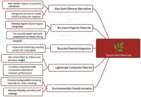
Figure 6.
Sustainable materials (rare-earth-free materials).
5. Performance Characteristics of Motors
The performance of electric motors significantly influences the overall efficiency, range, and driving experience of electric vehicles. Electric vehicles require high performance, and this mainly consists of achieving high torque values in the low- to medium-speed range while achieving high speeds through extensive resistance reduction capability [19]. Selecting an appropriate motor driver is an important step in the development of hybrid vehicles, requiring careful consideration of various factors such as efficiency, power density, and costs [63]. Permanent magnetic synchronous motors are a popular choice for the application of electric vehicles because they are very efficient, compact, and torque-efficient, which is superior to the performance of an inductive motor in many driving scenarios [64]. To optimize the lifespan and cost of permanent magnet synchronous motors in electric vehicles, advanced modelling and optimization techniques have been used to analyze their properties, such as torque and power [65]. Induction motors are generally less efficient than permanent magnetic motors, but they offer advantages, such as low costs and greater rigidity, that make them suitable for the first-class application of certain electric vehicles. The selection of an appropriate electric machine includes rotor geometry optimization, pole and interpolar gap ratio selection, machine number selection, current shape selection, and rotor cage type selection [66]. Although the torque density and torque ripple of switches are lower, they offer advantages such as simple construction and high fault tolerance, making them attractive for specific applications in electric cars where these factors are crucial. Loss modelling under electric vehicle conditions is crucial for optimizing efficiency, thermal management, and control strategies of electric drives (especially in traction motors and inverters). Table 3 presents the summary of loss models under EV conditions. Table 4 manifests the Losses and specific notes along with modeling tools.
Table 3.
Summary of loss models under EV conditions.
Table 4.
Losses and specific notes along with modeling tools.
Below is a breakdown of copper, core, and switching losses, along with appropriate modelling approaches and considerations under EV-specific dynamic operating conditions:
- (a)
- Copper (Conduction) Losses: Copper losses are a result of current flow in stator (and rotor, if a wound rotor is used) windings:
Pcu = I2·R(T)
I = RMS current (may vary with torque and speed);
R(T) = Winding resistance, which is temperature-dependant.
Considering the modeling aspects, temperature dependence is given by
R(T) = R0(1 + α(T − T0))
The dynamic EV conditions include the following:
- (1)
- Rapid acceleration/deceleration causes high transient current spikes.
- (2)
- Duty cycle and driving profile affect current magnitude and duration.
The modeling techniques involve the following:
- (1)
- Thermal–electrical co-simulation to capture the rise in R.
- (2)
- FEM-based loss calculation with spatial distribution.
- (b)
- Core Losses (Iron Losses): Losses in electric vehicle (EV) motors are critical in evaluating motor efficiency, especially under high-speed and inverter-driven conditions. These losses consist of hysteresis losses, eddy current losses, and excess losses. The Steinmetz equation and its variants are widely used to model these losses.
- (c)
- Core losses (iron losses): Losses in electric vehicle (EV) motors are critical in evaluating motor efficiency, especially under high-speed and inverter-driven conditions. These losses consist of hysteresis losses, eddy current losses, and excess losses. The Steinmetz equation and its variants are widely used to model these losses.
- (1)
- Classical Steinmetz Equation (CSE):
The classical Steinmetz Equation estimates core losses under sinusoidal flux excitation:
where the following definitions are provided:
P_core = k_h ∗ f ∗ B_peakα + k_e ∗ f2 ∗ B_peak2
- –
- P_core: Core loss per unit volume;
- –
- f: Frequency;
- –
- B_peak: Peak magnetic flux density;
- –
- k_h, k_e, and α: Empirical material coefficients.
Modified Steinmetz Equation (MSE)
To include excess losses, a modified Steinmetz Equation is used:
P_core = k_h ∗ f ∗ B_peakα + k_e ∗ f2 ∗ B_peak2 + k_ex ∗ f1.5 ∗ B_peak1.5
- (2)
- Generalized Steinmetz Equation (GSE)
For non-sinusoidal flux waveforms (e.g., PWM), the GSE is applied:
where the following definitions are provided:
P_core = (1/T) ∫0ᵀ k ∗ |dB(t)/dt|β dt
- –
- B(t): Time-varying magnetic flux density;
- –
- k and β: Material-specific empirical constants.
- (3)
- Improved Generalized Steinmetz Equation (iGSE)
The improved GSE accounts for waveform dependence and varying flux swing:
P_core = (1/T) ∫0ᵀ k ∗ (dB(t)/dt)β ∗ ΔB(t)(γ − β) dt
These equations are essential for loss estimation and thermal analysis in EV motor design. They form the basis for efficiency optimization and thermal control strategies.
The switching losses (Inverter) for IGBT or MOSFET are given by the following:
P_sw = 0.5 × V_dc × I_load × (t_on × f_sw + t_off × f_sw)
For wide-bandgap devices (SiC/GaN),
where the following definitions are provided:
P_sw = f_sw × Σ(E_on(I,V,T) + E_off(I,V,T))
- –
- V_dc: DC-link voltage;
- –
- I_load: Output current;
- –
- f_sw: Switching frequency;
- –
- t_on and t_off: Switching times;
- –
- E_on and E_off: Turn-on/-off energy losses dependent on I, V, and T.
Switching Losses (Inverter)
For IGBT or MOSFET devices,
P_sw = 0.5 × V_dc × I_load × (t_on × f_sw + t_off × f_sw)
For wide-bandgap devices (SiC/GaN),
where the following definitions are provided:
P_sw = f_sw × Σ(E_on(I,V,T) + E_off(I,V,T))
- –
- V_dc: DC-link voltage;
- –
- I_load: Output current;
- –
- f_sw: Switching frequency;
- –
- t_on and t_off: Switching times;
- –
- E_on and E_off: Turn-on/-off energy losses dependent on I, V, and T.
Dynamic Modeling
Switching losses vary with respect to the following:
- (1)
- DC-link voltage (rising with speed);
- (2)
- Motor current (related to torque demand);
- (3)
- Temperature (device performance varies).
The EV-specific features are as follows:
- (1)
- Regenerative braking–bidirectional switching;
- (2)
- High ambient and junction temperatures → consider thermal derating.
6. Challenges in REE-Free Motor Design
Designing electric vehicle engines without rare-earth elements poses several challenges, including achieving performance comparable to a permanent magnet engine, managing torque polarization and noise, and optimizing efficiency under various operating conditions. Mobilization motors free of rare earth, such as inductive motors, synchronous motors of the wound field, and switch-selective motors, are promising options for applications in electric vehicles, allowing the potential to reduce dependence on rare-earth materials and reducing risks with respect to the supply chain. One of the main challenges is to achieve high power density and efficiency without sacrificing the high magnetic performance of a rare-earth magnet. Another challenge is to mitigate torque bending and noise, particularly in switched resistance motors, which can have a negative impact on the driving experience. To overcome these challenges, innovative motor designs, advanced control strategies, and optimal material selection are needed. The improvement of torque density in non-rare-earth motors often results in an increase in the current density of stator windings, which may lead to increased loss and thermal management problems.
7. REE-Free Motor Topologies
- (a)
- Induction Motors
Induction motors are relatively efficient, simple and robust, easy to maintain, and low in cost [67]. Inductive motors are alternating current motors that produce the electrical current needed for torque in the rotor by electromagnetic induction from the rotating magnetic field of a rotor coil. Induction motors are well-established technologies, offering robust and cost-effective alternatives to permanent magnet motors for the propulsion of electric vehicles [68]. Inductive motors can be applied effectively in electric vehicles and provide a balance between performance, cost, and reliability [22,69]. However, inductive motors usually exhibit lower efficiency and power density compared to permanent magnet motors and need careful optimization to meet electric vehicle performance requirements. Induction motors are frequently used in industrial applications and benefit from advances in materials and manufacturing processes that have improved their performance and reliability over time. Optimizing the design of electric vehicle induction motors involves minimizing losses, improving cooling, and increasing power density. In order to overcome the limitations of inductive motors, researchers have studied advanced designs that improve efficiency and power density using silicon carbon dioxide inverters and innovative cooling technologies [70]. Advanced control strategies, such as field-oriented control and direct torque control, are used to optimize the performance of induction engines for electric vehicle applications.
- (b)
- Switched Reluctance Motors
The switch-resistant motor provides a unique alternative to permanent magnets and inductive motors with a simple and robust construction, avoiding the need for rare-earth magnets [71]. The switched resistance motor operates on the principle of magnetic resistance and generates torque via the tendency of the rotor to align with the static magnetic field. The switched resistance motor is designed to be adapted to demanding electric vehicle applications because of its simple structure, high fault tolerance, and high thermal operation capacity. The simple construction and absence of permanent magnets of the switched resistance motors make it an attractive alternative for the propulsion of electric vehicles. Despite its advantages, variable resistance motors generally suffer from lower torque density and high torque strokes compared to permanent magnetic motors, resulting in noise and vibration problems. Advanced control strategies, such as torque vectoring and current profiling, are used to reduce torque flows and improve the overall performance of electric vehicles with switched resistance motors. Research is focused on improving the design and control of modified reluctance engines to improve their performance and address the limitations of their widespread adoption in electric vehicles.
- (c)
- Synchronous Reluctance Motors
Synchronous reluctance motors are another promising alternative to permanent magnetic motors and have high efficiency and power density without the use of rare-earth materials. The synchronous reluctance motor combines reluctance torque and synchronous operation principles, and the rotor is designed to have significant poles aligned with the magnetic field generated by the spinning of the rotor. Synchronous reluctance motors have high efficiency, high energy factors, and rare earth magnets, making them attractive for use in electric vehicles. Synchronous reluctance engines are emerging as a viable option for electric vehicle propulsion and offer a balance between performance, cost, and sustainability. Optimization techniques such as finite element analysis and multiobjective optimization are used to improve the design of synchronous reluctance motors and improve their performance characteristics. Research and development efforts are continuing to improve performance and address the limitations of synchronous reluctance motors in order to facilitate their widespread use in electric vehicles. The design of electric motors takes into account factors such as electromagnetic forces on the rotor, which can cause vibrations [72]. Advances in simulation software enable engineers to accurately model and analyze these forces, thus reducing vibrations and noise in motor designs [73]. The implementation of effective thermal management strategies is essential to ensure the long-term reliability and performance of electric vehicle engines.
Switched reluctance motors (SRMs) and synchronous reluctance motors (SynRMs or simply reluctance motors) are both types of reluctance-based machines, but they differ in structure and operation. Our research question touches on torque ripple and NVH (noise, vibration, and harshness) and how certain changes can impact these parameters. We break them down as follows: torque ripples in switched reluctance motors (SRMs) and reluctance motors (Table 5 and Table 6):
Table 5.
Effect on torque ripples and NVH in general.
Table 6.
Comparison of SRM and synchronous reluctance motor.
- (1)
- Switched Reluctance Motor (SRM):
High torque ripples are a well-known disadvantage of SRMs.
This happens due to the following:
- Pulsed excitation of stator phases;
- Lack of continuous torque production (unlike PMSMs);
- Salient poles with no windings on the rotor.
The following affects the torque ripple:
- Number of stator and rotor poles: More poles generally reduce ripples.
- Current profiling (advanced control): Shaped current waveforms can smooth torque.
- Overlap between phases: Increasing overlap reduces ripple.
- Magnetic saturation and detent torque: Impacts torque waveform sharpness.
- (2)
- Reluctance Motor (Synchronous Reluctance Motor):
- Generally, lower torque ripples are generated compared to SRMs.
- Rotor is a saliency-based rotor (no windings or PMs).
- Operates with sinusoidal currents (when driven with vector control).
- Torque ripple may come from rotor slotting and magnetic anisotropy.
The following affects torque ripples:
- Rotor design (barrier shape): Smoother flux path → smoother torque.
- Control strategy: Field-oriented control reduces ripple.
- Slot/pole combinations: Optimized combinations minimize harmonics.
The NVH (noise, vibration, and harshness) in SRMs is as follows:
- Very noisy, especially when under load.
- Causes:
- ○
- Discrete magnetic force pulses.
- ○
- Radial force variations due to magnetic attraction.
- ○
- High torque ripple (vibrations are mechanically transmitted).
- Acoustic noise is a serious design concern.
Reduction in NVH:
- Skewing of stator or rotor poles.
- Use of acoustic barriers or damping structures.
- Optimizing switching strategy.
- Improved current profiling and magnetic design.
- (3)
- Synchronous Reluctance Motors (SynRMs):
- Generally quieter than SRM.
- But it may still produce the following:
- ○
- Noise from slotting effects.
- ○
- Radial forces in rotor barrier design.
- Less torque ripple = better NVH naturally.
- (d)
- Ferrite Magnet Motors
Ferrite magnetomotors are a cost-effective alternative to permanent magnetic magnetomotors for rare earths, which are composed of iron oxides and other inexpensive materials. Ferritic magnets are cheaper than rare-earth magnets, but they usually have lower energy density and require larger motors to achieve comparable performance [64]. Ferrite magnets can be used to withstand higher temperatures [26]. Although not as strong as rare-earth magnets, their use reduces dependence on critical materials. These engines are suitable for applications that do not require high performance, such as in auxiliary systems that use pumps [74]. In order to create an efficient motor, proper techniques are needed to improve performance, such as optimizing motor design and improving the magnetic properties of ferric magnets. Figure 7 shows the alternative motor technologies that use non-short-field elements for various motor types.
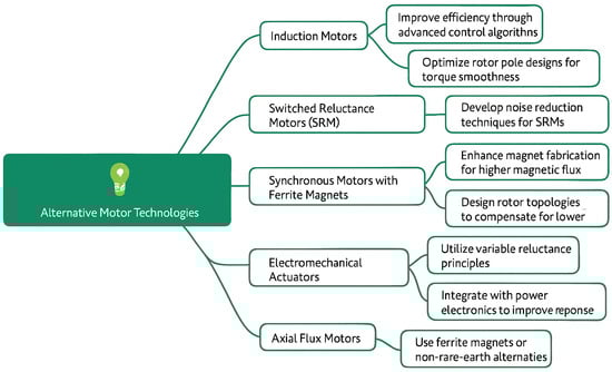
Figure 7.
Alternative motor technologies (non-rare-earth materials).
Thermal Analysis and Cooling Strategies for REE-Free Electric Motor Designs:
Rare-earth-element (REE)-free electric motors (e.g., switched reluctance motors [SRMs], synchronous reluctance motors [SynRMs], induction motors [IMs]) pose unique challenges in thermal management due to the following: lower efficiency (compared to PM motors), higher copper losses (due to higher current requirements), and increased torque ripple and vibration, which contribute to localized heating.
1. Thermal Analysis in REE-Free Motors
(a) Loss Sources
Thermal analysis starts by accurately modeling all heat sources:
- Copper (I2R) losses: Usually dominant; strongly dependent on load profile.
- Core (iron) losses: Hysteresis and eddy current losses, varying with frequency and flux density.
- Additional losses: Stray, friction, windage, and switching losses (in inverter-fed systems).
(b) Modeling Approaches
- Lumped parameter thermal network (LPTN): Fast approximation for early-stage design.
- Three-dimensional FEA-based thermal simulations: High-fidelity modeling using tools like ANSYS, Motor-CAD, or COMSOL.
- Coupled electromagnetic–thermal simulations: Combine FEA motor models with transient thermal solvers for accurate heat distribution.
(c) Temperature Hotspots
- Windings (especially end windings and slot fill areas).
- Stator core (especially around teeth).
- Rotor (in induction motors or laminated SynRMs).
2. Cooling Strategies for REE-Free Motors
Because REE-free motors often require higher current density or have less optimal thermal paths, efficient cooling is crucial:
(a) Passive Cooling
Enhanced thermal pathways: Use high thermal conductivity materials (e.g., aluminum housings, potting).
Improved slot fill: Optimized winding techniques reduce thermal resistance.
Heat sinking: Direct conduction through the housing to the vehicle’s chassis.
(b) Active Cooling
Air Cooling: Suitable for low–medium power; cost-effective but limited heat capacity.
Liquid Cooling:
Direct stator water jackets.
Direct oil cooling (injection into windings or end-turns).
Cooling channels in rotor shafts (for IMs with high slip).
(c) Advanced Cooling Techniques
Immersion cooling: The entire motor is immersed in dielectric fluid (used in some EVs).
Heat pipe or vapor chamber: For localized hotspot dissipation.
Additive manufacturing: Complex internal cooling paths for optimized thermal routing.
The best practices are as follows:
- Ensure uniform heat distribution to reduce thermal stress and insulation degradation.
- Co-simulate with real EV drive cycles (e.g., WLTP) to assess peak and average temperatures.
- Validate with thermal imaging, embedded sensors (NTCs and RTDs), and thermocouples during testing.
- Consider degradation effects: Overheating leads to faster aging of winding insulation and magnets (if used).
Some of the real-world examples include the following:
- BMW i3 uses an REE-free motor with integrated oil cooling and tightly coupled thermal management with the vehicle system.
- Switched reluctance drives (e.g., from Turntide or Dyson) rely heavily on direct cooling of windings and advanced control to limit thermal rise.
Comparative studies and side-by-side analysis of different types of required motors are manifested in the form of a tabulation in Table 7.
Table 7.
Comparative studies and side-by-side analysis of different types of required motors.
The control methods for rare-earth-free (REE-free) motors used in electric vehicles (EVs) are crucial due to the unique electromagnetic characteristics of these motors compared to conventional permanent magnet machines. Control strategy for different types of motors are shown in Table 8. The control techniques are as follows:
Table 8.
Control strategy for different types of motors.
- Hysteresis Current Control: Simple but causes high switching frequencies.
- Angle-Based Current Profiling: Optimal phase current profile to minimize torque ripple.
- Direct Torque Control (DTC): Improved dynamic response and torque accuracy.
- Model Predictive Control (MPC): Advanced method allowing real-time optimization.
- Sensorless Control: Position estimation using flux linkage or inductance profiles.
Challenges: Torque ripple, acoustic noise, and complex control logic.
- (a)
- Synchronous Reluctance Motor (SynRM) Control
SynRMs operate without magnets or rotor windings and require precise control due to their low power factor.
The control techniques are as follows:
Field-Oriented Control (FOC): Uses d-q axis transformation for decoupled torque/flux control.
Maximum Torque per Ampere (MTPA): Ensures the highest torque for a given current.
Sensorless Control: Rotor position is estimated using high-frequency signal injection or back EMF.
Advantages: Simpler rotor, high speed, and REE-free.
- (b)
- Induction Motor (IM) Control
Proven REE-free option with wide EV use (e.g., older Tesla models).
The control techniques are as follows:
Scalar (V/f) Control: Basic and cost-effective but not efficient for dynamic performance.
Field-Oriented Control (FOC): Widely used for high-performance EV control.
Direct Torque Control (DTC): Offers faster torque response but may induce torque ripple.
Sensorless Control: Flux and speed estimation from stator voltages and currents.
Advantages: Robust, low-cost, and mature technology.
- (c)
- Ferrite-Permanent Magnet Synchronous Motor (Ferrite-PMSM) Control
Uses low-cost ferrite magnets instead of rare-earth types.
The control techniques are as follows:
FOC with MTPA Strategy: Especially important due to the lower magnetic strength of ferrites.
Field Weakening: Extends the speed range by reducing flux at high speeds.
Sensorless FOC: Minimizes the need for encoders in cost-sensitive EV applications.
Challenges: Lower torque density than NdFeB-PMSMs, but suitable for low-to-medium power EVs.
- (d)
- General Emerging Trends
Machine Learning-Based Control: Adaptive control and fault diagnosis.
Digital Twin Integration: For real-time control and monitoring.
Multiphase Motor Control: Improves fault tolerance and performance in REE-free topologies.
The existing literature and industry standards (e.g., IEEE and IEC) currently do not offer a uniform classification schema specifically tailored to rare-earth-free motors. A comparative table that clearly differentiates these motor types based on magnetic material usage, torque density, control complexity, and thermal behavior, and EV suitability distinguishes REE-free motor types based on electromagnetic principles, rotor/stator characteristics, and control requirements. The characteistic standardization based on the comparison of different topologies of EV motors are shown in Table 9. We aim to bring clarity and standardization in comparing these topologies for electric vehicle (EV) applications.
Table 9.
Characteristic standardization based on the comparison of different topologies of EV motors.
- Torque Ripple in Rare-Earth-Free Motors:
Torque ripple refers to periodic variations in the electromagnetic torque of the motor. It results in acoustic noise, vibrations (NVH issues), and reduced drive quality. This is a critical concern in switched reluctance motors (SRMs) and synchronous reluctance motors (SynRMs), both of which are rare-earth-free. The technical bottlenecks in rare-earth free motors for torque ripple, thermal management and cooling strategy in rare-earth-free motors. are presented in Table 10, Table 11 and Table 12 respectively.
Table 10.
Technical bottlenecks: torque ripple in rare-earth-free motors.
Table 11.
Technical bottlenecks: thermal management in rare-earth-free motors.
Table 12.
Technical bottlenecks: cooling strategy in rare-earth-free motors.
Control-Related Bottlenecks:
- Current waveform shaping is challenging in SRMs due to non-linear magnetization.
- Advanced control strategies (e.g., direct torque control, model predictive control) demand high computational resources and fast sensor feedback for ripple suppression.
- In cost-sensitive applications, the use of low-resolution position sensors in SynRMs and SRMs leads to poor commutation, increasing ripples.
Suggested Technical Enhancements:
- Rotor skewing and pole arc optimization (especially in SRMs);
- Current profiling and asymmetric voltage control;
- Use of high-frequency current injection for position detection to refine commutation
- Multiphase machine topologies (e.g., 6-phase SRMs) for ripple cancellation;
- Thermal Management in rare-earth-free motors.
Rare-earth-free motors generally have lower efficiency or higher loss densities, especially in rotors. Losses manifest as copper losses, core losses, and additional switching losses, requiring effective thermal control.
System-Level Bottlenecks:
- Lack of integrated thermal design in early-stage motor modeling.
- Increased packaging constraints in compact EV platforms make it harder to deploy complex cooling systems.
- Inadequate thermal monitoring at the rotor level due to a lack of embedded sensors.
Technical Enhancements:
- Incorporation of computational fluid dynamics (CFD) in the early design phase for hotspot prediction;
- Direct oil spray cooling on rotors in IM and SRM to extract losses;
- Use of thermally conductive encapsulation materials in stator and windings;
- Advanced thermal management materials like graphene-infused epoxy or phase change materials (PCMs).
While rare-earth-free motors offer long-term material and cost advantages, they introduce significant design and control challenges in torque ripple suppression and thermal management. Both areas demand multi-disciplinary optimization, involving magnetic design, control strategies, and cooling technologies. Addressing these bottlenecks is essential to realize performance parity with rare-earth-based PMSMs.
The following are some of the motors employed in some of the major EV manufacturers’ vehicles:
- BMW: Use of EESMs with no rare earths, fifth-generation eDrive, high-speed operation (~30,000 RPM), and compact size.
- Renault/Nissan: Use of wound rotor synchronous motors (WRSMs).
- Tesla and others: Mention the trade-off strategies when moving away from NdFeB-based PMs.
- Rare-earth-free motors now compete closely with PM motors in terms of efficiency, thermal stability, and cost-effectiveness.
- Control complexity and acoustic noise remain challenges for SRMs but are being addressed with advanced algorithms.
- High-speed operation and compactness are being achieved through improved rotor designs and cooling systems, even without rare earths.The comparative table of OEMs and their motor types and characteristics are presented in Table 13 and the quantitative performance associated with different types of motor are shown in Table 14.
Table 13. Comparative table of OEMs and their motor types and characteristics.
Table 14. Quantitative performance associated with different types of motor.
8. Other Emerging Technologies
In addition to the above-mentioned motor types, continued research is being carried out into new motor technologies and designs for use in electric vehicles. An interesting technology is the axial flow motor. The motor is characterized by its high torque density and compact size [64]. Another field of research is the development of new wind configurations that reduce losses and improve thermal management [75]. The development of high-temperature insulation materials allows the motor to operate at higher temperatures and therefore increase the power density. Emission reduction efforts are influenced by the need to reduce emissions, and the goal is to significantly reduce average vehicle emissions by specific deadlines [76]. Therefore, it is important to continue improving the technology of electric vehicles. The selection of the appropriate motor specifications is the foundation of electric vehicle powertrain design and has a direct impact on vehicle performance, efficiency, and range. The essential parameters include torque speed characteristics, power output, voltage level, and current ratings, and they must be carefully adjusted to the specific requirements of the vehicle’s application [77]. The chosen motor must deliver sufficient torque to facilitate acceleration and climbing, while the power output determines the vehicle’s maximum speed and overall performance capacity. The current and current rating must be compatible with battery systems and power electronics to ensure seamless integration and efficient energy transfer [78]. In addition, the size and weight of the motors impose constraints on the design of the vehicle, affecting the packaging and overall mass of the vehicle, thereby affecting energy consumption and handling dynamics. By taking into account these interrelated factors carefully, engineers can select engine specifications to optimize the performance, efficiency, and driving experience of electric vehicles. Finite element analysis is an indispensable tool for simulating and optimizing electric motor design, providing valuable insights into electromagnetic, thermal, and mechanical behaviors. FEA can accurately predict the distribution of magnetic currents, torque production, and losses within the motor by dividing the geometry of the motor into discrete elements. Electronic magnetic FEA simulations facilitate engine geometry optimization, coating design, and winding configuration optimization to maximize torque performance, reduce losses, and improve overall efficiency. Thermal FEA simulations provide detailed temperature maps to help engineers identify hot points and optimize cooling strategies to prevent overheating and ensure reliable operation [79]. Mechanical FEA simulations evaluate structural integrity, predict stress distribution, and analyze vibration modes, allowing the design of robust and durable motor structures that can withstand demanding operating conditions. Through iterative FEA simulations, engineers can refine the design of the engine, explore design compromises, and verify performance predictions, which ultimately leads to optimized electric motors meeting the strict requirements of performance, efficiency, and reliability. Effective heat management is the main factor in ensuring the longevity, performance, and safety of electric vehicle engines, as excessive heat generation can cause insulation degradation, permanent magnetic densification, and low efficiency of the engine [80]. Comprehensive thermal analyses, using analytical and computational methods, are essential in understanding the mechanisms of heat generation, predicting temperature distributions, and optimizing cooling strategies. Heat is produced in the motor due to a number of losses, including copper losses in the windings, iron losses in the core, and mechanical losses due to friction and winding. Proper prediction of these losses is essential to effective thermal management design. Computational fluid dynamics simulation allows a detailed analysis of the air flow pattern and the heat transfer coefficient and facilitates the design of efficient cooling systems. With a strategically integrated cooling channel and heat sink, as well as forced convection, engineers can effectively discharge heat, maintain optimal operating temperatures, and improve the reliability and lifetime of engines. Modern motor design trends make motors more compact and efficient [81]. Optimization of cooling systems, including air conditioning, liquid cooling, and high-thermal-conductivity materials, is essential to maximize mechanical performance and reliability [82]. In addition, proper design and implementation of thermal management systems can improve battery life and performance [83]. The design optimization factors considered in motor manufacturing using reduced rare-earth materials are illustrated in Figure 8.
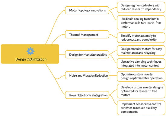
Figure 8.
Design optimization factors considered during the design.
- 1.
- Mesh Quality:
High-quality meshing directly affects the accuracy and convergence of electromagnetic field simulations. Mesh refinement must be concentrated in areas of high flux density gradients, such as air gaps, tooth tips, and corners of rotor/stator slots. Metrics like aspect ratio, skewness, and element count (ideally, adaptive meshing) should be reported to ensure numerical stability and precision.
Example: The airgap was meshed with elements ≤ 0.2 mm in size, ensuring >95% element quality based on skewness metrics, to accurately resolve local flux variations and cogging torque.
- 2.
- Saliency Ratio Tuning (for reluctance and synchronous machines):
Saliency ratio (Ld/LqL_d/L_qLd/Lq) is a vital parameter in torque production, particularly for synchronous reluctance and IPM motors. FEA enables accurate estimation of inductance variations under different current loading and rotor positions.
Example: Parametric FEA sweeps were conducted to optimize rotor barrier dimensions to achieve a saliency ratio > 4.0, balancing torque capability with mechanical integrity.
- 3.
- Validation Process:
Simulation results must be validated against analytical models or experimental measurements. This can include back-EMF waveform comparison, torque–speed profiles, or core loss estimations.
Example: The simulated no-load back-EMF waveforms matched measured values within ±3%, and the torque ripple predicted by FEA was within ±5% of test results under identical load cycles.
- 4.
- Loss Distribution Analysis:
FEA should be used to quantify core loss (using methods like Bertotti’s model), copper loss, eddy current loss in magnets (for IPMs), and stray losses. Spatially resolved loss plots aid in hotspot identification and cooling system design.
- 5.
- Electromagnetic NVH Analysis:
Modal and harmonic force analysis from FEA identifies sources of acoustic noise and vibration. Force density on stator teeth can be used as input for structural FEA to predict sound pressure levels.
9. Technology and Research Gaps
- (a)
- Existing Materials in EV Motors (Typically Rare-Earth-Based)
The commonly used rare-earth materials are as follows:
- NdFeB (neodymium–iron–boron) magnets;
- Dy (dysprosium) for high-temperature stability;
- Copper windings;
- Electrical steel (e.g., silicon steel) laminations.
- ➢
- Technology Gaps
- Thermal Stability:
- ○
- High-performance rare-earth magnets degrade at elevated temperatures (>150 °C).
- ○
- Current insulation systems and cooling techniques are reaching their limits.
- Cost and Supply Chain:
- ○
- Heavy dependence on China for rare-earth materials.
- ○
- Volatile pricing and geopolitical instability hinder scalability.
- Demagnetization Risk:
- ○
- Magnets may suffer irreversible demagnetization under short-circuit or high-temperature events.
- ○
- Limited real-time monitoring and fault-tolerant designs.
- Magnetic Losses:
- ○
- Despite high energy density, PM motors have eddy current and hysteresis losses, especially at high speeds.
- ➢
- Research Gaps
- Alternative Coatings for NdFeB Magnets:
- ○
- Need for high-temperature, corrosion-resistant coatings.
- ○
- Few scalable or cost-effective options.
- End-of-Life Recycling:
- ○
- Very limited commercial processes for magnet recycling.
- ○
- Need advanced separation and reprocessing techniques.
- Magnet-to-Motor Integration:
- ○
- Better mechanical bonding, reduced air gaps, and novel flux-path strategies are under-researched.
- Material Modeling at Micro/Nanoscale:
- ○
- Inadequate modeling of microstructural behavior (grain boundary diffusion and domain switching).
- ○
- Lack of AI/ML-based material informatics for optimization.
- (b)
- Rare-Earth-Free Materials for EV Motors
The commonly used rare-earth-free materials are as follows:
- Ferrites (low-cost, non-RE);
- Amorphous/nanocrystalline magnetic materials;
- Switched reluctance machines (SRMs) and synchronous reluctance machines (SynRM) (no PMs);
- Soft Magnetic Composites (SMC).
- ➢
- Technology Gaps
- Low Power Density:
- ○
- Ferrites and SMCs have lower magnetic flux densities than NdFeB.
- ○
- Reluctance machines require more volume to match torque.
- 2.
- Control Complexity:
- ○
- SRMs and SynRMs have nonlinear torque characteristics and high torque ripples.
- ○
- Advanced real-time control algorithms are needed.
- 3.
- Thermal Management:
- ○
- Ferrites have lower thermal conductivity.
- ○
- Alternative cooling strategies (e.g., spray, immersion) are still experimental.
- 4.
- Manufacturing and Assembly:
- ○
- Higher tolerances needed for reluctance motors (air-gap sensitivity).
- ○
- Three-dimensional printing or additive manufacturing methods are not yet mature enough for high-performance magnetic materials.
- ➢
- Research Gaps
- Material Development:
- ○
- Need for high-performance ferrite or cobalt-free magnets with better coercivity and temperature performance.
- ○
- Optimization of nanocrystalline materials for reduced core loss at high frequencies.
- 2.
- Advanced Core Designs:
- ○
- Lack of optimal stator/rotor topology studies that fully exploit anisotropy in reluctance designs.
- 3.
- Loss Modeling Under EV Duty Cycles:
- ○
- Most material loss studies are static or sinusoidal. Real EV profiles involve high transients and non-sinusoidal excitation.
- 4.
- Sustainability Metrics:
- ○
- Little LCA (life cycle assessment) data for rare-earth-free materials.
- ○
- Tradeoffs between recyclability, CO2 footprint, and motor efficiency are under-explored.
- 5.
- FEA and Multiphysics Integration:
- ○
- Lack of integrated electro-thermal-mechanical FEA tools that support rare-earth-free designs with complex geometries.The Technology gap and research gap in rare-earth and rare-earth-free materials is manifested in Table 15 and the Performance comparison of PMSM and rare-earth-free PMSM technologies is depicted in Table 16.
Table 15. Technology gap and research gap in rare-earth and rare-earth-free materials.
Table 16. Performance comparison of PMSM and rare-earth-free PMSM technologies.
Further, a comparative performance table is shown based on key parameters, such as torque density, efficiency, power factor, cost, and thermal behavior, under different operating conditions.
Compared to traditional PMSMs, rare-earth-free PMSMs demonstrate a trade-off between cost-effectiveness and performance. While the torque density and peak efficiency are typically lower, recent advances in rotor topology (such as V-shaped or spoke-type IPM) and ferrite magnet optimization have significantly narrowed the gap. For instance, torque density improvements of up to 30% have been reported in ferrite-based motors using flux-concentrating designs. Moreover, enhanced control algorithms and cooling strategies are being developed to improve partial load efficiency and thermal stability.
10. Future Research Directions
The shift to electric vehicle engines that do not require rare-earth elements is a major engineering project. Despite the challenges, research has begun to bring interesting and promising results. Soon, there will be a variety of designs to choose from, each with its own complex compromises. All-out performance dynamics, costs, weight, power density, and motor manufacturing are all important factors to consider. It is particularly difficult to predict which designs will dominate, as success in the market depends on a combination of equally complex economic factors. However, one thing that is starting to emerge is that non-REE motors may very well become commonplace in the future. If we want this result, we must persevere and work together. However, we do not recognize any obstacles that engineers cannot overcome to ensure that the next generation of electronic vehicles is less harmful to the environment. These REE-free motors have already been developed faster in ORNL and elsewhere with artificial intelligence-enabled motor design tools. Recently, a debate has emerged that contrasts the technical benefits of REE magnets with environmental and ethical concerns about their widespread use. In the near future, these points may have less weight. Manganese bismuth (MnBi) is a permanent magnet material that does not contain rare-earth elements (REEs), and it has been studied in collaboration with Pulmet Inc., Iowa State University, and Pittsburgh University. Together, these engineers developed an MnBi magnet-based surface-mount permanent magnet synchronous motor. Compared to ferric magnetics, this magnetics have stronger remanence and coerciveness, but they are not as powerful as nickel–iron–boron magnets (NdFeB). The researchers discovered that MnBi magnets could achieve torque outputs of the same speed as NdFeB magnets, despite an enormous 62% increase in volume and 65% increase in weight. Fortunately, the researchers propose a solution that could reduce the total cost of the motor by 32% by replacing the NdFeB magnet with a MnBi magnet. Removing only the heavy elements of the rare earth used in certain magnets is another way to reduce the rare-earth content of an engine. For example, NdFeB magnets often contain trace quantities of heavy rare-earth metals, such as dysprosium, at high temperatures, making them more forceful (neodymium and other light-grade metals are richer than heavy-grade metals). The lack of their use has the disadvantage of reducing high-temperature coercivity. Figure 9 shows future perspectives and emerging technologies that do not have REEs in EV-based motors. The use of reduced rare-earth elements is also one of the possible technological innovations shown in Figure 10.
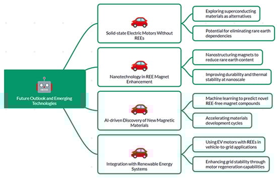
Figure 9.
Future outlook and emerging technologies of REE-free EV motors.
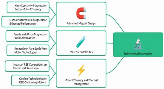
Figure 10.
Technological innovations with reduced REE alternatives.
Therefore, keeping the rotor cool is a main concern when building such motors. In the last year, the Oak Ridge National Institute installed a 100-kilowatt high-speed-drive motor free of heavy rare-earth materials. Integration of power electronics is another great feature. Inverters are a component of power electronics that convert the direct current of a battery into the alternating current required by a motor at a certain frequency. The fundamental challenge we faced was to keep the magnets from overheating. Permanent magnets have excellent conductivity. In addition, the current of the electrical conductor is generated when the conductor moves within a magnetic field, as in the case of a rotating magnet while a motor is in operation. These currents can demagnetize magnets by heating them, even if they do not add torque. To reduce heating, magnetic devices composed of electrically isolated thin segments can be used to divert the current of the circulation. These segments had a thickness of only 1 mm in our engine. The N50 NdFeB magnet is selected because it can be used in a hot environment of up to 80 °C. In order to spin the rotor at a speed of up to 20,000 rpm, we had to use a carbon fiber epoxy system to stiffen the outer diameter. Our analysis of the motor prototype showed that, to keep it from overheating at maximum speed, the motor must be pressured. In order to avoid the use of heavy REEs in our design, this is an acceptable compromise, although it is not ideal. The construction of a synchronous motor using an electromagnet (i.e., wire coil) rotor, with or without a ferrite magnet, is probably the most promising solution to producing a powerful motor without relying entirely on REEs. However, to achieve this, power needs to be provided to these coils. The traditional method is to use carbon brushes to make electrical contact with slip rings, i.e., rotating metal rings. Electromagnets of the rotor can be powered using this method by applying a direct current. However, these motors are not suitable for use in EVs, as these brushes are deformed and produce dust. A rotating transformer, also known as an exciter, was developed by engineers to solve this problem. They use capacitance or inductive technology to wirelessly transmit electricity to the rotor when it is rotating. Unlike traditional permanent magnet synchronous motors, the magnetic fields of these motors can be finely tuned by regulating the current flowing through their electromagnets. This enabled the use of a method called field weakening to ensure high efficiency across a wide range of operating speeds, and electric vehicles became a promising alternative to traditional combustion engines, but improved thermal management was crucial to widespread adoption [84]. The thermal management system plays an important role in maintaining optimal operating temperatures of batteries, motors, and electrical equipment and ensuring optimal performance and long-term durability [85]. Advanced thermal management strategies, such as the integration of heat pumps and heat harvesting technologies, can significantly reduce energy consumption [86]. Improved thermal management will facilitate the adoption of more efficient and reliable electric vehicles, accelerating their adoption and contributing to cleaner and more sustainable transportation futures [82]. An effective battery thermal management system is essential to ensure the optimal performance and longevity of the battery pack, especially in the fast expansion of electric vehicles [87]. Maintaining a stable temperature range of 15 to 35 degrees C is essential to maximizing the efficiency and longevity of lithium batteries [88]. Innovative cooling technologies, including modified air cooling and liquid cooling, improve temperature uniformity and cooling efficiency [89]. Furthermore, by incorporating advanced control strategies such as model prediction control, the performance of thermal management systems is improved by optimizing cooling and heating processes based on real-time operation conditions [90]. The establishment of criteria for assessing battery thermal management is essential [91]. The use of battery thermal management systems eliminates heat in order to avoid safety and performance degradation [92]. The development of efficient battery thermal management systems is essential to the widespread adoption of electric vehicles [83,93]. The HVAC system is important for light vehicles and consumes fuel [94]. The battery and electrical drive components can become very hot, so thermal management is necessary to maintain temperatures below 60 °C. The economic and market dynamics of REEs, the future employment of non-REEs, and policy initiatives are compared in Figure 11.
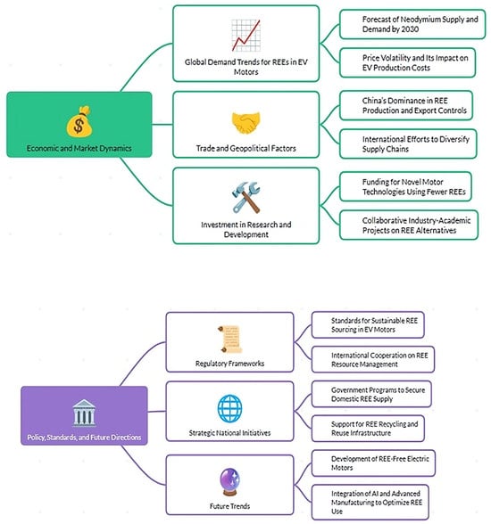
Figure 11.
Comparison of economic and market dynamics of REE, future employment of non-REEs, and policy initiatives.
The transition to rare-earth-element (REE)-free electric vehicle (EV) motors is an engineering megaproject driven by the dual imperatives of sustainability and cost reduction. Although technical challenges remain, research has shown promising directions across materials, design architecture, and control strategies. By organizing the innovation landscape into a three-layer framework—materials, structure, and control—a clearer roadmap for future development emerges.
- ➢
- Materials Layer: Novel REE-Free Magnet and Magnetic Material Systems
The most crucial innovation driver in REE-free motor development is the discovery and enhancement of alternative magnetic materials. The following materials and research projects are notable:
- Manganese Bismuth (MnBi): Investigated by Pulmet Inc., Iowa State University, and the University of Pittsburgh, MnBi offers improved coercivity and thermal stability compared to ferrites. Though its energy product is lower than NdFeB, MnBi magnets have been successfully integrated into surface-mounted PMSMs with comparable torque at higher mass and volume [95].
- Aluminum–Nickel–Cobalt (AlNiCo): Though dated, newer nanostructuring techniques have revitalized interest in AlNiCo as a medium-coercivity magnet option suitable for moderate-speed EV applications.
- Ferrites: Soft ferrites (e.g., strontium hexaferrites) are undergoing particle alignment and doping research to enhance remanence and form factor suitability for rotor integration.
- Amorphous and Nanocrystalline Alloys: These materials offer low core loss and are useful in high-speed stator designs. Research by Hitachi Metals and ORNL explores nanocrystalline tape-wound cores for high-efficiency designs.
- Electromagnetic Excited Rotors: Using wound-field synchronous motor (WFSM) architectures, magnet-free systems are being developed that rely on ferromagnetic rotor materials and field coils.
- ➢
- Structure Layer: Rotor–Stator Topology and Thermal Design Innovations
Structural design choices directly affect torque density, efficiency, and manufacturability:
- Axial Flux Topologies: Companies like Magnax and YASA are experimenting with REE-free axial flux architectures using ferrite magnets and optimized air gap designs.
- Segmented Rotors and Electrically Insulated Laminations: As demonstrated by ORNL, thin laminations (~1 mm) and segmented rotors minimize eddy current losses and magnet heating, reducing the risk of demagnetization.
- Carbon Fiber Overwrap: High-speed rotors (up to 20,000 rpm) are mechanically reinforced with carbon–epoxy composites to handle centrifugal forces, especially when using heavier REE-free magnets.
- Rotor Cooling Technologies: Embedded oil channels and localized spray cooling around hotspots are being explored. For example, ORNL’s 100 kW prototype integrates rotor pressure cooling with minimal REE content.
- ➢
- Control Layer: Power Electronics and Intelligent Control
Advanced control strategies are essential to compensate for the limitations of REE-free materials:
- Field-Oriented Control (FOC) and Field Weakening: Used in wound-field motors, this approach allows the fine-tuning of the magnetic field for extended operating range and torque control.
- Sensorless Control Techniques: Being adopted in switched reluctance and synchronous reluctance motors to reduce cost and improve reliability, as in the work from TU Delft and Hanyang University.
- Model Predictive Control (MPC): Improves thermal management by predicting temperature evolution and adapting inverter switching patterns accordingly. Used by Hyundai Mobis and NREL in integrated motor-inverter testing setups.
- Wireless Excitation Systems: Capacitive or inductive excitation mechanisms (rotary transformers or “exciters”) are under active development to eliminate slip rings in wound-field machines—enabling maintenance-free operation.
The push towards REE-free motors is no longer limited by scientific curiosity—it is becoming a commercial and policy-driven necessity. By systematically advancing materials (e.g., MnBi, doped ferrites), structural design (e.g., segmented rotors, oil cooling), and intelligent control (e.g., field weakening, MPC), researchers are breaking new ground. Collaborative efforts from institutions like ORNL, Pulmet Inc., and academic partners have proven that the REE-free motor vision is feasible and accelerating.
To foster continued innovation, it is recommended to establish a consortium-based roadmap focused on the following:
- Material substitutions with scalable synthesis pathways.
- Modular rotor/stator designs with integrated thermal solutions.
- AI-accelerated co-design of motor control and structure.
Together, these efforts will not only enable the wide adoption of sustainable EV technologies but will also reduce geopolitical and environmental dependencies on rare-earth supply chains.
11. Conclusions
In conclusion, while electric vehicles present a sustainable alternative to traditional vehicles by reducing pollution and dependence on fossil fuels, their widespread adoption is hindered by challenges such as cost and infrastructure. Innovations in motor technology, particularly the development of rare-earth-free alternatives, are crucial for overcoming these barriers and advancing the electric vehicle industry.
Author Contributions
Conceptualization, S.S.R., C.K.S., E.R.C. and T.S.; methodology, S.S.R., C.K.S., E.R.C. and T.S.; validation, S.S.R., C.K.S., E.R.C. and T.S.; formal analysis, investigation; resources, data curation, writing—original draft preparation, writing—review and editing, and visualization, S.S.R., C.K.S., E.R.C. and T.S. All authors have read and agreed to the published version of the manuscript.
Funding
This research received no external funding.
Acknowledgments
The authors thank their respective institutions for the support provided in the writing of this paper.
Conflicts of Interest
The authors declare no conflicts of interest.
References
- Acharige, S.S.G.; Haque, M.E.; Arif, M.T.; Hosseinzadeh, N. Review of Electric Vehicle Charging Technologies, Configurations, and Architectures. arXiv 2022, arXiv:2209.15242. [Google Scholar] [CrossRef]
- Cui, X.; Zhang, Z.; Gong, D.; Liu, J.; Shen, J. Allocation of Electric Taxi Charging: Assessing the Layout of Charging Stations Based on Charging Frequency. Teh. Vjesn. Tech. Gaz. 2022, 29, 1069–1079. [Google Scholar] [CrossRef]
- Park, J.; Jang, I.G.; Hwang, S.-H. Torque Distribution Algorithm for an Independently Driven Electric Vehicle Using a Fuzzy Control Method: Driving Stability and Efficiency. Energies 2018, 11, 3479. [Google Scholar] [CrossRef]
- Ahmed, M.; Zheng, Y.; Amine, A.; Fathiannasab, H.; Chen, Z. The role of artificial intelligence in the mass adoption of electric vehicles. Joule 2021, 5, 2296–2322. [Google Scholar] [CrossRef]
- Chakraborty, P.; Parker, R.; Hoque, T.; Cruz, J.; Du, L.; Wang, S.; Bhunia, S. Addressing the range anxiety of battery electric vehicles with charging en route. Sci. Rep. 2022, 12, 5588. [Google Scholar] [CrossRef]
- Alzehawi, I.S.M.; Faris, W.F.; Darsivan, F.J.; Rafeeq, M. Electric Vehicle Modeling: A Review. In Lecture Notes in Mechanical Engineering; Springer Nature: Singapore, 2023; pp. 199–205. [Google Scholar] [CrossRef]
- Merve, Ş.K. The Use of Induction Motors in Electric Vehicles; IntechOpen: London, UK, 2023. [Google Scholar]
- Macharia, V.M.; Garg, V.K.; Kumar, D. A review of electric vehicle technology: Architectures, battery technology and its management system, relevant standards, application of artificial intelligence, cyber security, and interoperability challenges. IET Electr. Syst. Transp. 2023, 13, e12083. [Google Scholar] [CrossRef]
- Vuddanti, S.; Karknalli, V.; Salkuti, S.R. Design and comparative analysis of three phase, four phase and six phase switched reluctance motor topologies for electrical vehicle propulsion. Bull. Electr. Eng. Inform. 2021, 10, 1495–1504. [Google Scholar] [CrossRef]
- Liubarskyi, B.G.; Overianova, L.V.; Riabov, I.S.; Iakunin, D.I.; Ostroverkh, O.O.; Voronin, Y.V. Estimation of the Main Dimensions of the Traction Permanent Magnet-Assisted Synchronous Reluctance Motor. Electr. Eng. Electromech. 2021, 3–8. [Google Scholar] [CrossRef]
- Lipman, T.E.; Maier, P. Advanced materials supply considerations for electric vehicle applications. MRS Bull. 2021, 46, 1164–1175. [Google Scholar] [CrossRef]
- Jetin, B. Who will control the electric vehicle market. Int. J. Automot. Technol. Manag. 2020, 20, 156. [Google Scholar] [CrossRef]
- Bhatt, P.; Mehar, H.; Sahajwani, M. Electrical Motors for Electric Vehicle—A Comparative Study. SSRN Electron. J. 2019. [Google Scholar] [CrossRef]
- Mohammadi, A.; Badewa, O.A.; Chulaee, Y.; Lewis, D.D.; Essakiappan, S.; Manjrekar, M.D.; Ionel, D.M. Design Optimization of a Direct-Drive Wind Generator with a Reluctance Rotor and a Flux Intensifying Stator Using Different PM Types. IEEE Trans. Ind. Appl. 2024, 60, 6113–6123. [Google Scholar] [CrossRef]
- Kaplanović, S.; Živojinović, T. Financial incentives for electric vehicles adoption: Experiences and evidences from European countries. Int. J. Traffic Transp. Eng. 2022, 12. [Google Scholar] [CrossRef] [PubMed]
- Dutta, P. Assessment of environmental implications of electric vehicles: A review. J. Res. Eng. Appl. Sci. 2021, 6, 188–195. [Google Scholar] [CrossRef]
- Apribowo, C.H.B.; Ahmad, M.; Maghfiroh, H. Fuzzy Logic Controller and Its Application in Brushless DC Motor (BLDC) in Electric Vehicle—A Review. J. Electr. Electron. Inf. Commun. Technol. 2021, 3, 35–43. [Google Scholar] [CrossRef]
- Szumska, E.M. Regenerative Braking Systems in Electric Vehicles: A Comprehensive Review of Design, Control Strategies, and Efficiency Challenges. Energies 2025, 18, 2422. [Google Scholar] [CrossRef]
- Pastura, M.; Barater, D.; Nuzzo, S.; Franceschini, G. Multi Three-Phase Hairpin Windings for High-Speed Electrical Machine: Possible Implementations. In Proceedings of the 2021 IEEE Workshop on Electrical Machines Design, Control and Diagnosis (WEMDCD), Modena, Italy, 8–9 April 2021; pp. 113–118. [Google Scholar] [CrossRef]
- Agrawal, M.; Rajapatel, M.S. Global Perspective on Electric Vehicle 2020. Int. J. Eng. Res. Technol. 2020, 9, 8–11. [Google Scholar] [CrossRef]
- Reyes, A.R.; Nasr, A.; Sinoquet, D.; Hlioui, S. Robust Design Optimization Taking into Account Manufacturing Uncertainties of a Permanent-Magnet-Assisted Synchronous Reluctance Motor. IEEE Trans. Ind. Appl. 2023, 59, 4567–4577. [Google Scholar]
- Firdaus, A.Z.A.; Azmi, S.A.; Kamarudin, K.; Hwai, L.; Ali, H.; Azalan, M.S.Z.; Kasa, Z.C.M. Assessment of Control Drive Technologies for Induction Motor: Industrial Application to Electric Vehicle. J. Phys. Conf. Ser. 2021, 1878, 12047. [Google Scholar] [CrossRef]
- Ameen, N.A.; Abdulabbas, A.K.; Nekad, H.J. Response of five-phase synchronous reluctance motor with direct torque control technique. Int. J. Adv. Technol. Eng. Explor. 2021, 8, 1454. [Google Scholar] [CrossRef]
- Heidari, H.; Rassõlkin, A.; Kallaste, A.; Vaimann, T.; Andriushchenko, E.; Belahcen, A.; Lukichev, D.V. A Review of Synchronous Reluctance Motor-Drive Advancements. Sustainability 2021, 13, 729. [Google Scholar] [CrossRef]
- Adăscăliței, C.; Marțiș, R.A.; Karaisas, P.; Marțiș, C.S. In-Depth Exploration of Design and Analysis for PM-Assisted Synchronous Reluctance Machines: Implications for Light Electric Vehicles. Machines 2024, 12, 361. [Google Scholar] [CrossRef]
- Ibrahim, M.N.; Tawfiq, K.B.; Rashad, E.M.; Sergeant, P. Synchronous reluctance machines: Performance evaluation with and without ferrite magnets. In IOP Conference Series Materials Science and Engineering; IOP Publishing: Bristol, UK, 2020; p. 12107. [Google Scholar] [CrossRef]
- He, T.; Wang, Y.; Bao, M.; Qu, R. Design and validation of a high efficiency synchronous reluctance motor. IEEE Trans. Ind. Appl. 2025, 61, 123–133. [Google Scholar] [CrossRef]
- Accetta, A.; Cirrincione, M.; Pucci, M.; Sferlazza, A. Space-Vector State Dynamic Model of the SynRM Considering Self, Cross-Saturation and Iron Losses and Related Identification Technique. IEEE Trans. Ind. Appl. 2023, 59, 3320–3331. [Google Scholar] [CrossRef]
- Wang, J.; Ren, C.; Liu, Z.; Mao, M.; Naifar, O. Research on Direct Drive Technology of the Permanent Magnet Synchronous Motor for Urban Rail Vehicles. Math. Probl. Eng. 2022, 2022, 8312121. [Google Scholar] [CrossRef]
- Cao, J.; Zhang, Y. Design of high power switched reluctance motor controller. J. Phys. Conf. Ser. 2021, 1885, 52023. [Google Scholar] [CrossRef]
- Hughes, A.L. Electric Motors and Drives: Fundamentals, Types and Applications. 1990. Available online: http://cds.cern.ch/record/1599077 (accessed on 1 February 2025).
- Nishanth, F.; Wang, B. Topology Optimization of Electric Machines: A Review. In Proceedings of the IEEE Energy Conversion Congress and Exposition (ECCE), Vancouver, BC, Canada, 9–13 October 2022; pp. 1–8. [Google Scholar]
- Lyu, Z.; Wu, X.; Gao, J.; Tan, G. An Improved Finite-Control-Set Model Predictive Current Control for IPMSM under Model Parameter Mismatches. Energies 2021, 14, 6342. [Google Scholar] [CrossRef]
- Lin, S.; Chang, L.; Su, P.; Li, Y.; Hua, W.; Shen, Y. Research on High-Torque-Density Design for Axial Modular Flux-Reversal Permanent Magnet Machine. Energies 2023, 16, 1691. [Google Scholar] [CrossRef]
- Zeghlache, A.; Mekki, H.; Benkhoris, M.F.; Djerioui, A.; Ziane, D.; Zeghlache, S. Robust Fault-Tolerant Control of a Five-Phase Permanent Magnet Synchronous Motor under an Open-Circuit Fault. Appl. Sci. 2024, 14, 5190. [Google Scholar] [CrossRef]
- Venugopal, C.N.; Prabhakar, R.S. Induction Motor Speed Control Using Fuzzy Logic Controller. Int. J. Electr. Comput. Eng. (IJECE) 2008, 2, 2620. Available online: https://publications.waset.org/5366/induction-motor-speed-control-using-fuzzy-logic-controller (accessed on 1 January 2025).
- Gao, S.; Wei, Y.; Zhang, D.; Qi, H.; Wei, Y. A Modified Model Predictive Torque Control with Parameters Robustness Improvement for PMSM of Electric Vehicles. Actuators 2021, 10, 132. [Google Scholar] [CrossRef]
- Mencou, S.; Ben Yakhlef, M.; Tazi, E.B. Fuzzy Logic Speed Controller for Robust Direct Torque Control of Induction Motor Drives. In Digital Technologies and Applications (ICDTA 2023); Motahhir, S., Bossoufi, B., Eds.; Lecture Notes in Networks and Systems; Springer: Cham, Switzerland, 2023; Volume 668, pp. 601–611. [Google Scholar] [CrossRef]
- Chandrasekaran, S.; Durairaj, S.; Padmavathi, S. A Performance Improvement of the Fuzzy Controller-Based Multi-Level Inverter-Fed Three-Phase Induction Motor with Enhanced Time and Speed of Response. J. Electr. Eng. Technol. 2021, 16, 1131–1141. [Google Scholar] [CrossRef]
- Misra, P.; Kumar, B. Rotor Resistance Estimation for Improved Performance of MRAS Based Sensorless Speed Estimation of Induction Motor Drives. In Intelligent Algorithms for Analysis and Control of Dynamical Systems; Kumar, R., Singh, P., Mathur, A., Eds.; Springer: Singapore, 2021; pp. 201–212. [Google Scholar] [CrossRef]
- Mirzahosseini, R.; Namaghi, E.R. An Analytical Formula for Back EMF Waveform of a Counter-Rotating Dual-Rotor Non-Slotted Axial Flux Permanent Magnet Synchronous Machine. IET Gener. Transm. Distrib. 2024, 18, 107–120. [Google Scholar] [CrossRef]
- Farah, N.; Talib, H.N.; Bin Ibrahim, Z.; Abdullah, Q.; Aydoğdu, Ö.; Lazi, J.M.; Isa, Z. Fuzzy membership functions tuning for speed controller of induction motor drive: Performance improvement. Indones. J. Electr. Eng. Comput. Sci. 2021, 22, 130–140. [Google Scholar] [CrossRef]
- Al-Asady, H.A.-J.; Fakhruldeen, H.F. Volts/Hz Control of Three Phase Induction Machine: Matlab Simulink. J. Phys. Conf. Ser. 2021, 1818, 12089. [Google Scholar] [CrossRef]
- Zaky, M.S.; Metwaly, M.K. Improved MRAS Observer with Rotor Flux Correction Terms and FLC-Based Adaptive Law for Sensorless Induction Motor Drives. Sci. Rep. 2025, 15, 14769. [Google Scholar] [CrossRef]
- Alattar, M.S.; Alsammak, A.N.B. A Survey Paper on Six Phase Induction Motor Drive. Al-Rafidain Eng. J. 2020, 25, 24–31. [Google Scholar] [CrossRef]
- Deepika, D.; Alka, M.; Surekha, B. Controlling Speed in Induction Motors with Fuzzy Logic and a PI Controller. I-Manag. J. Electr. Eng. 2022, 16, 27. [Google Scholar] [CrossRef]
- Hasan, F.A.; Rashad, L.J. Combining Fractional-Order PI Controller with Field-Oriented Control Based on Maximum Torque per Ampere Technique Considering Iron Loss of Induction Motor. AIMS Electron. Electr. Eng. 2024, 8, 380–403. [Google Scholar] [CrossRef]
- Tikkani, A.; Karasani, R.R.; Rao, K.V.G.; Kalyan, C.N.S.; Goud, B.S.; Bajaj, M.; Tuka, M.B. Fuzzy-2 Deployment in Indirect Vector Control and Hybrid Space Vector Modulation for a Two-Level Inverter Fed Induction Motor Drive. Sci. Rep. 2025, 15, 13379. [Google Scholar] [CrossRef]
- Benbouhenni, H.; Driss, A.; Lemdani, S. Indirect active and reactive powers control of doubly fed induction generator fed by three-level adaptive-network-based fuzzy inference system—Pulse width modulation converter with a robust method based on super twisting algorithms. Electr. Eng. Electromech. 2021, 31–38. [Google Scholar] [CrossRef]
- Fahassa, C.; Abbou, A.; Zahraoui, Y.; Akherraz, M. Induction motor performance improvement using a five-level inverter topology and sliding mode controllers. Bull. Electr. Eng. Inform. 2023, 12, 2693–2704. [Google Scholar] [CrossRef]
- Vahedi, M.; Zarif, M.H.; Kalat, A.A. Speed control of induction motors using neuro-fuzzy dynamic sliding mode control. J. Intell. Fuzzy Syst. 2015, 29, 365–376. [Google Scholar] [CrossRef]
- Jia, C.; Liu, W.; He, H.; Chau, K. Superior energy management for fuel cell vehicles guided by improved DDPG algorithm: Integrating driving intention speed prediction and health-aware control. Appl. Energy 2025, 394, 126195. [Google Scholar] [CrossRef]
- Jia, C.; Liu, W.; He, H.; Chau, K. Deep reinforcement learning-based energy management strategy for fuel cell buses integrating future road information and cabin comfort control. Energy Convers. Manag. 2024, 321, 119032. [Google Scholar] [CrossRef]
- Brando, G.; Dannier, A.; Spina, I. Performance Analysis of a Full Order Sensorless Control Adaptive Observer for Doubly-Fed Induction Generator in Grid Connected Operation. Energies 2021, 14, 1254. [Google Scholar] [CrossRef]
- Alimin, R.; Siahaan, I.H.; Saputra, A. Pemodelan Torque Vectoring Sebagai Upaya Untuk Meningkatkan Stabilitas Pengendalian Mobil Listrik. J. Tek. Mesin 2021, 18, 44–50. [Google Scholar] [CrossRef]
- Tian, J.; Yang, M.; Altan, A. Hierarchical control of differential steering for four-in-wheel-motor electric vehicle. PLoS ONE 2023, 18, e0285485. [Google Scholar] [CrossRef]
- Wang, Y.; Zhang, H.; Liu, X.; Li, F.; Chen, J. Design and Model Predictive Control of Axial-Flux Switched-PM Machines for Electric Vehicles. IEEE Trans. Veh. Technol. 2023, 72, 2021–2034. [Google Scholar]
- Li, S.; Han, Z.; Zhao, Y.; Deng, H. Torque Distribution Strategy for Improved Stability and Economy in Distributed Drive EVs. IEEE Trans. Control Syst. Technol. 2024, 32, 678–691. [Google Scholar]
- Wu, J.; Sun, M.; Zhou, L.; Li, H. Hierarchical Control for Stability Enhancement in Four Wheel Independently Actuated EVs. IEEE Trans. Autom. Sci. Eng. 2025, 21, 150–164. [Google Scholar]
- Zhang, N.; Wang, J.; Li, Z.; Xu, N.; Ding, H.; Zhang, Z.; Guo, K.; Xu, H. AFS and DYC Coordinated Optimal Control for Four-Wheel Independent Drive Electric Vehicles Based on MAS Model. Sensors 2023, 23, 3505. [Google Scholar] [CrossRef]
- Wang, J.; Gao, S.; Wang, K.; Wang, Y.; Wang, Q. Wheel torque distribution optimization of four-wheel independent-drive electric vehicle for energy efficient driving. Control. Eng. Pract. 2021, 110, 104779. [Google Scholar] [CrossRef]
- Li, Y.; Wang, Y.; Zhang, Z.; Li, J. Investigation and Development of the Brushless and Magnetless Wound Field Synchronous Motor Drive System for Electric Vehicle Application. World Electr. Veh. J. 2023, 14, 81. [Google Scholar] [CrossRef]
- Patel, M.S.; Nguyen, L.; Sharma, R.K.; Di Gioia, A.; Usmani, E. Experimental development of a hybrid wound-field synchronous motor with brushless capacitive excitation for passenger EV applications. IEEE Trans. Transp. Electrif. 2024, 11, 467–477. [Google Scholar]
- Hsieh, M.-F.; Ngo, D.-K.; Thao, N.G.M. Flux Intensifying Feature of Permanent Magnet Assisted Synchronous Reluctance Motor with High Torque Density. Electronics 2022, 11, 397. [Google Scholar] [CrossRef]
- Meddour, A.R.; Rizoug, N.; Leserf, P.; Vagg, C.; Burke, R.; Larouci, C. Optimization of the Lifetime and Cost of a PMSM in an Electric Vehicle Drive Train. Energies 2023, 16, 5200. [Google Scholar] [CrossRef]
- Kim, J.; Lee, J.; Kim, H. A Comparative Study of Pole–Slot Combination with Fractional Slot Concentrated Winding in Outer Rotor Permanent Magnet Synchronous Generator for Hybrid Drone System. Machines 2024, 12, 464. [Google Scholar] [CrossRef]
- Silitonga, A.S.; Silitonga, N. Pengaruh Penurunan Kecepatan Elektromotor Untuk Menggerakkan Bowl Separator Terhadap Kinerja Separator Di Pabrik Tapioka PT Hutahaean. IRA J. Tek. Mesin Apl. (IRAJTMA) 2023, 2, 51–57. [Google Scholar] [CrossRef]
- Zhou, K.; Gu, M.; Zheng, Y. Design of High-Speed Motor System for EV Based on 1200 V SiC-MOSFET Power Module. Actuators 2025, 14, 216. [Google Scholar] [CrossRef]
- Khan, M.Y.A. Enhancing Electric Vehicle Performance: A Case Study on Advanced Motor Drive Systems, Integration, Efficiency, and Thermal Management. Control Syst. Optim. Lett. 2025, 3, 20–27. [Google Scholar] [CrossRef]
- Krichi, M.; Noman, A.M.; Fannakh, M.; Raffak, T.; Haidar, Z.A. Sustainable Electric Micromobility Through Integrated Power Electronic Systems and Control Strategies. Energies 2025, 18, 2143. [Google Scholar] [CrossRef]
- Abdallah, S.H.; Almousa, M.T.; Ben Salem, F.; Tounsi, S. Systemic Optimization of Electric Vehicles Power System. World Electr. Veh. J. 2025, 16, 207. [Google Scholar] [CrossRef]
- Steegers, F.; Weidermann, C.; Klöpzig, M.; Sattel, T. Dynamics and Vibrations of Rotors of Electrical Drives with Additively Manufactured Materials at Cryogenic Temperatures. In IOP Conference Series Materials Science and Engineering; IOP Publishing: Bristol, UK, 2022; p. 12048. [Google Scholar] [CrossRef]
- Hussien, M.G.; Elbarbary, Z.M.S.; Hassan, A.E.-W. High-Performance Sensorless Operation of Motor-Generator Set with an Improved Torque-Ripple Minimization Strategy. Front. Energy Res. 2022, 10, 870850. [Google Scholar] [CrossRef]
- Burye, R.S.; Arumalla, R.T.; Figarado, S. Investigation of Torque Ripple in Voltage-Source-Inverter Driven Induction Motor Using Space Vector-Based Harmonic Elimination PWM Scheme. IEEE Trans. Energy Convers. 2023, 38, 3102–3112. [Google Scholar]
- Xiao, D.; Zhang, G. Advanced AC Motor Drive System Applications in Electric Vehicles: Topologies, Integration and Control Trends. Energies 2023, 16, 4210. [Google Scholar]
- Singh, R.; Lapp, G.; Velardo, J.; Long, P.T.; Mochizuki, M.; Akbarzadeh, A.; Date, A.; Mausolf, K.; Busse, K. Battery cooling options in electric vehicles with heat pipes. Front. Heat Mass Transf. 2021, 16. [Google Scholar] [CrossRef]
- Mohammadi, A.; Chulaee, Y.; Cramer, A.M.; Boldea, I.; Ionel, D.M. Axial Flux Permanent Magnet Vernier Machine with Single wound Dual Stator and Spoke Permanent Magnet Rotor for Electric Vehicle In wheel Traction. IEEE Trans. Veh. Technol. 2023, 72, 9876–9886. [Google Scholar]
- Kassakian, J.G. Principles of Power Electronics, 2nd ed.; MIT Press: Cambridge, MA, USA, 2023. [Google Scholar]
- Donazzolo, R. Torque Control for a Flux-Switching Permanent-Magnet Motor Based on FEM Data. 2018. Available online: https://aaltodoc.aalto.fi:443/bitstream/123456789/33661/1/final_Donazzolo_Riccardo_2018.pdf (accessed on 1 December 2024).
- Arzillo, A.; Braglia, P.; Nuzzo, S.; Barater, D.; Franceschini, G.; Gerada, D.; Gerada, C. Challenges and Future opportunities of Hairpin Technologies. In Proceedings of the 2020 IEEE 29th International Symposium on Industrial Electronics (ISIE), Delft, The Netherlands, 17–19 June 2020; pp. 277–282. [Google Scholar] [CrossRef]
- Bergfried, C.; Späck-Leigsnering, Y.; Seebacher, R.; Eickhoff, H.; Muetze, A. Thermal Finite Element Modeling and Simulation of a Squirrel-Cage Induction Machine. IEEE Trans. Ind. Electron. 2024, 72, 1842–1853. [Google Scholar] [CrossRef]
- Konovalov, D.; Tolstorebrov, I.; Eikevik, T.M.; Kobalava, H.; Radchenko, M.; Hafner, A.; Radchenko, A. Recent Developments in Cooling Systems and Cooling Management for Electric Motors. Energies 2023, 16, 7006. [Google Scholar] [CrossRef]
- Ali, H.M. Thermal management systems for batteries in electric vehicles: A recent review. Energy Rep. 2023, 9, 5545–5564. [Google Scholar] [CrossRef]
- Previati, G.; Mastinu, G.; Gobbi, M. Thermal Management of Electrified Vehicles—A Review. Energies 2022, 15, 1326. [Google Scholar] [CrossRef]
- Sahoo, P. A Review on Thermal Management in Electric Vehicle Battery System by Liquid Cooling. In SAE Technical Papers on CD-ROM/SAE Technical Paper Series; SAE International: Warrendale, PA, USA, 2021. [Google Scholar] [CrossRef]
- Emran, A.; Pawar, B.; Chavan, S.; Hemkemeyer, D.; Sharma, V.; Garg, S.; Franke, K. Advance Thermal Management System for Electric Vehicle—An Indian Case Study. In SAE Technical Papers on CD-ROM/SAE Technical Paper Series; SAE International: Warrendale, PA, USA, 2024. [Google Scholar] [CrossRef]
- S, P.; Selvan, A.M. Investigation on the Effectiveness of Phase Change Materials in Battery Thermal Management System of Electric Vehicles. In SAE Technical Papers on CD-ROM/SAE Technical Paper Series; SAE International: Warrendale, PA, USA, 2025; Volume 1. [Google Scholar] [CrossRef]
- Hwang, F.S.; Confrey, T.; Reidy, C.; Picovici, D.; Callaghan, D.; Culliton, D.; Nolan, C. Review of battery thermal management systems in electric vehicles. Renew. Sustain. Energy Rev. 2023, 192, 114171. [Google Scholar] [CrossRef]
- Rahmani, A.; Dibaj, M.; Akrami, M. Recent Advancements in Battery Thermal Management Systems for Enhanced Performance of Li-Ion Batteries: A Comprehensive Review. Batteries 2024, 10, 265. [Google Scholar] [CrossRef]
- He, L.; Jing, H.; Zhang, Y.; Li, P.; Gu, Z. Performance Research of Integrated Thermal Management System for Battery Electric Vehicles with Motor Waste Heat Recovery. J. Energy Storage 2024, 84, 110893. [Google Scholar] [CrossRef]
- Gungor, S.; Gocmen, S.; Cetkin, E. A Review on Battery Thermal Management Strategies in Lithium-Ion and Post-Lithium Batteries for Electric Vehicles. J. Therm. Eng. 2023, 9, 1078–1099. [Google Scholar] [CrossRef]
- Kharabati, S.; Saedodin, S. A Systematic Review of Thermal Management Techniques for Electric Vehicle Batteries. J. Energy Storage 2023, 75, 109586. [Google Scholar] [CrossRef]
- Wiriyasart, S.; Hommalee, C.; Sirikasemsuk, S.; Prurapark, R.; Naphon, P. Thermal management system with nanofluids for electric vehicle battery cooling modules. Case Stud. Therm. Eng. 2020, 18, 100583. [Google Scholar] [CrossRef]
- Wang, H.; Meng, Y.; Zhang, Q.; Amini, M.R.; Kolmanovsky, I.; Sun, J.; Jennings, M. MPC-based Precision Cooling Strategy (PCS) for Efficient Thermal Management of Automotive Air Conditioning System. In Proceedings of the 2019 IEEE Conference on Control Technology and Applications (CCTA), Hong Kong, China, 19–21 August 2019. [Google Scholar] [CrossRef]
- Pekala, S.M.; Zacharias, N.; Kulkarni, K. Method and System for Efficient Thermal Management in Electric Vehicles. In SAE Technical Papers on CD-ROM/SAE Technical Paper Series; SAE International: Warrendale, PA, USA, 2024; Volume 1. [Google Scholar] [CrossRef]
Disclaimer/Publisher’s Note: The statements, opinions and data contained in all publications are solely those of the individual author(s) and contributor(s) and not of MDPI and/or the editor(s). MDPI and/or the editor(s) disclaim responsibility for any injury to people or property resulting from any ideas, methods, instructions or products referred to in the content. |
© 2025 by the authors. Licensee MDPI, Basel, Switzerland. This article is an open access article distributed under the terms and conditions of the Creative Commons Attribution (CC BY) license (https://creativecommons.org/licenses/by/4.0/).