1. Introduction
In the field of gesture recognition, with the continuous advancement of technologies such as computer vision and deep learning, the ability of machines to process images and videos has been significantly enhanced [
1]. Concurrently, improvements in sensor technologies, including cameras and LiDAR, have enabled robots to capture and interpret human gestures with greater accuracy [
2]. Gesture recognition is a human–computer interaction technology that not only sends commands through contactless means, but also provides a natural signal interaction foundation for building smart cities [
3]. It can also be used to recognize sign language and achieve barrier-free communication with groups with hearing and language barriers. It can also be used in sports rehabilitation systems to train hand muscles by guiding patients and athletes to perform gesture movements and to compare the completion rate of gesture movements to complete hand health assessments [
4]. In addition, gesture recognition technology can also be used for teaching and practicing fine hand operations in virtual environments and can provide feedback on the effectiveness of simulated practical operations through accurate judgment [
5]. Gesture recognition technology has broad application prospects.
In recent years, collaborative efforts between the University of Science and Technology of China and Harbin Institute of Technology have led to the development of a real-time bare-hand gesture recognition system based on the “big-small hand” concept, which demonstrates exceptionally high recognition rates for common gestures [
6]. Furthermore, the Department of Computer Science and Technology at Tsinghua University has proposed a novel appearance-based gesture recognition technology, successfully implementing an online system capable of recognizing 12 types of gestures with remarkable accuracy [
7]. These achievements highlight China’s leading position in gesture recognition technology research and its significant contributions to the development of intelligent human–computer interaction.
Prior to the maturity of gesture recognition technology, traditional mobile robots relied on remote controllers for operation [
8]. Data gloves or electromagnetic waves are commonly used to capture hand movements. For instance, IBM introduced a device called “Data Glove” [
9]. In contrast, machine vision-based gesture-controlled mobile robots eliminate the need for remote controllers, allowing users to control robot movements simply by performing gestures in front of the sensor [
10,
11,
12]. Gesture recognition technology based on machine vision enables users to interact with robots and computers in a more intuitive and natural manner [
13]. This is particularly beneficial for special groups, such as individuals with mobility impairments, as gesture control technology can facilitate easier interaction with robots, thereby enhancing their quality of life and autonomy [
14,
15]. This technology holds significant potential in various fields, including smart homes, medical assistance, and industrial production, offering users more intelligent and convenient services and experiences [
16,
17,
18,
19].
In the application of thermal imaging technology, since 1960, thermal imaging technology has been predominantly applied in military [
20] and medical [
21] fields. However, with the advancement of modern chip technology and the enhancement of computational power, thermal imaging technology has been widely popularized. Thermal imaging works by utilizing radiation in the infrared region of the spectrum, especially wavelengths between 3 and 14 μm. Specialized devices called thermal imagers use the infrared part of the spectrum to obtain spatial temperature distributions of the captured scene [
22]. Each pixel in the temperature map corresponds to the relative temperature at that point in the environment. Through proper calibration, bias removal, and subsequent processing, these temperature maps can be easily applied to real-time scenarios [
23].
Thermal imaging technology relies entirely on the detection of infrared radiation (IR) emitted by objects, eliminating the need for any external light sources. This fundamental characteristic endows it with a faster processing speed compared to RGB imaging technology, as the absence of external lighting dependencies streamlines the signal acquisition and processing pipeline [
24]. In recent years, driven by the decreasing costs of integrated chips, enhanced portability, and flexible design architectures, thermal imaging devices have witnessed a significant expansion in civilian applications [
25]. These technologies are now widely employed in various fields, including body temperature screening [
26], insulation defect detection [
27], and electrical hotspot monitoring [
28], demonstrating their versatility and practical value in real-world scenarios. Due to the above advantages, thermal imaging technology and gesture recognition are becoming increasingly popular and widely used [
29].
The aim of this study is to design and implement a lightweight gesture recognition system based on thermal imaging sensors to meet the non-contact control requirements of mobile robots and smart home devices in complex environments. Specifically, by constructing a complete technical chain of “data collection–model training–embedded deployment”, the following objectives are achieved: standardizing the construction of thermal imaging gesture datasets using Python, developing lightweight neural network models suitable for thermal infrared features with the Keras framework, efficiently transplanting the models to STM32 microcontrollers through STM32CubeMX6.9.2, and, finally, realizing real-time linkage between gesture recognition and robot motion control on a hardware platform integrating the MLX90640 thermal imaging sensor and an LCD display module. The manufacturer of MLX90640 is Melexis (Ypres, Belgium). This design focuses on solving the recognition robustness problem of traditional RGB vision in low-light scenarios, and provides an efficient human–computer interaction solution for resource-constrained embedded devices through the combination of thermal imaging technology and lightweight algorithms.
The lightweight gesture recognition system based on thermal imaging sensors enables users to interact with devices in a more intuitive and natural manner, regardless of lighting conditions. Especially for special groups such as people with mobility impairments, the machine vision-based gesture control technology can help them interact with robots more conveniently, improving their quality of life and autonomy. It can play an important role in smart homes, medical assistance, industrial production, and other fields, providing users with more intelligent and convenient services and usage experiences.
2. Materials and Methods
2.1. The Structure of the Independent Thermal Imaging Gesture Control Design
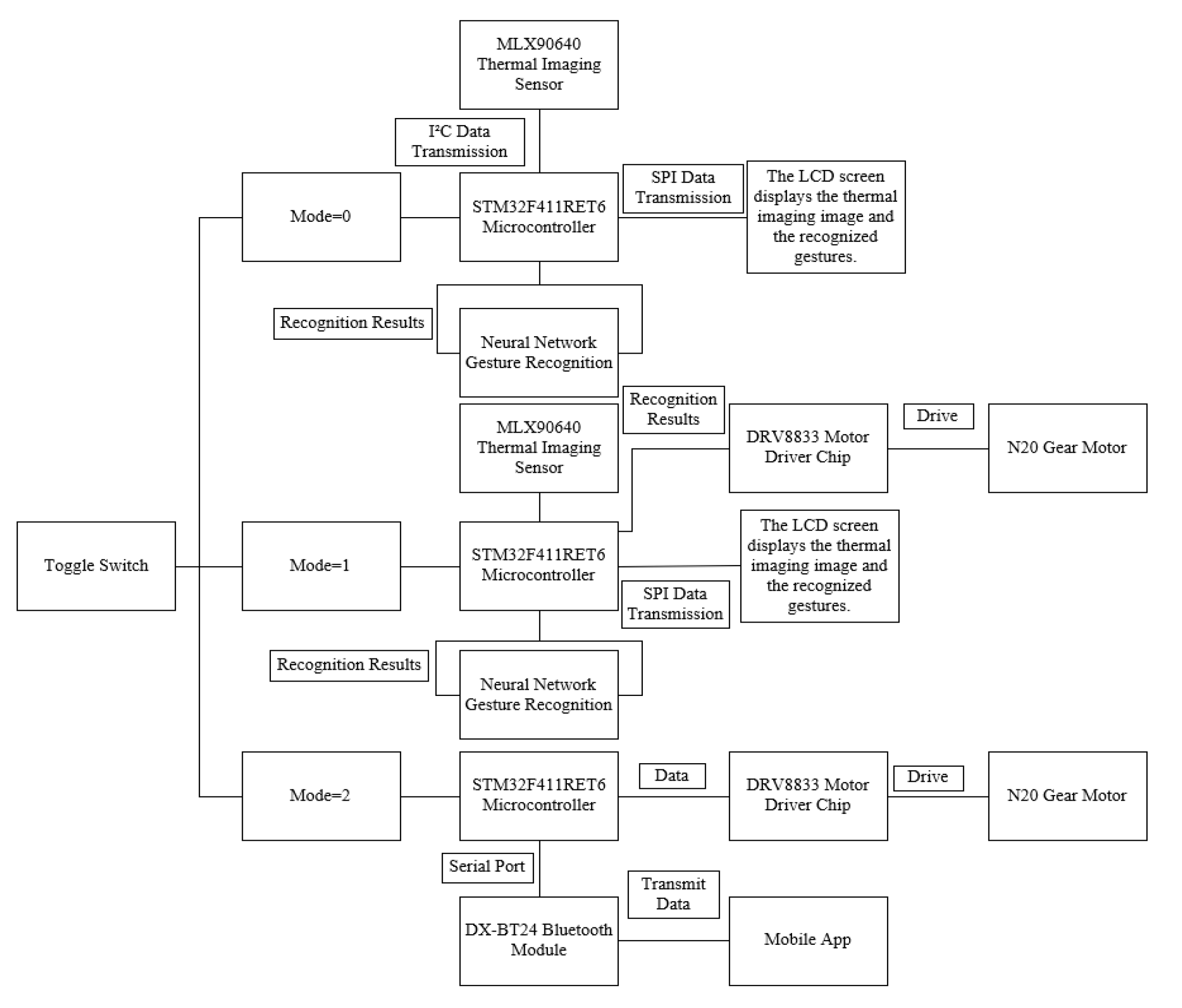
The structural diagram of the standalone thermal-based gesture control design is illustrated in
Figure 1. All tasks, including image capture, image recognition, and controlling the robot platform’s movement, are executed on the STM32F411RET6 microcontroller. The sensor employed in this design is the MLX90640, a thermal imaging sensor. Prior to the platform’s operation, a neural network must be trained, and the dataset required for this training is also collected using this platform.
During dataset collection, the MLX90640 sensor transmits the temperature values of each pixel within the measurement area to the STM32F411RET6 microcontroller via the I2C bus. The microcontroller then sends these temperature data to a computer through a serial port. Using Python, the computer stores the data in arrays to create the dataset. Subsequently, Python utilizes this dataset to train the neural network. Once the neural network is trained, it is deployed to the STM32F411RET6 microcontroller’s program using the STM32CubeMX 6.9.2 software.
This integrated approach ensures that the entire process, from data acquisition to gesture recognition and robot control, is efficiently managed within a single embedded system, highlighting the design’s compactness and real-time performance.
Three control modes are controlled by a three-position toggle switch, as shown in
Table 1. During platform operation, the microcontroller first checks the state of the boat-type switch connected to its IO ports. If the switch is toggled to position 0, both input IO ports of the microcontroller are set to low level, activating Mode 0. In this mode, the platform’s functionality is limited to capturing thermal images, performing recognition, and displaying the images and recognition results on the LCD screen. The MLX90640 sensor transmits the temperature values of each pixel within the measurement area to the STM32F411RET6 microcontroller via the I
2C bus. The microcontroller maps these temperature values to a 0–255 color scale and sends the corresponding RGB color data to the LCD screen via the SPI bus for display. Simultaneously, the microcontroller uses the embedded neural network program to recognize gestures from the thermal images and displays the recognition results on the LCD screen. Additionally, the LCD screen shows the highest and lowest temperatures within the measurement area.
If the switch is toggled to position 1, the PB4 input pin of the microcontroller is set to a high level, while the PB3 input pin remains at a low level, activating Mode 1. In this mode, the platform’s functionality extends beyond that of Mode 0 to include controlling the platform’s movement based on the recognition results. The sensor data acquisition and LCD display functions remain the same as in Mode 0. However, after recognizing the gesture, the microcontroller adjusts the output IO port levels to control the motor rotation, thereby altering the platform’s movement state.
When the switch is toggled to position 2, the PB4 input pin is set to a low level, and the PB3 input pin is set to a high level, activating Mode 2. In this mode, the MLX90640 sensor and LCD screen are inactive. Instead, a custom Android application connects to the Bluetooth module and sends data to it. The Bluetooth module transmits the received data to the microcontroller via a serial port. The microcontroller then adjusts the output IO port levels based on the received data, controlling the platform’s movement state accordingly.
This multi-mode operation design ensures flexibility and adaptability, allowing the platform to perform gesture recognition, thermal imaging display, and motion control based on user requirements and operational contexts.
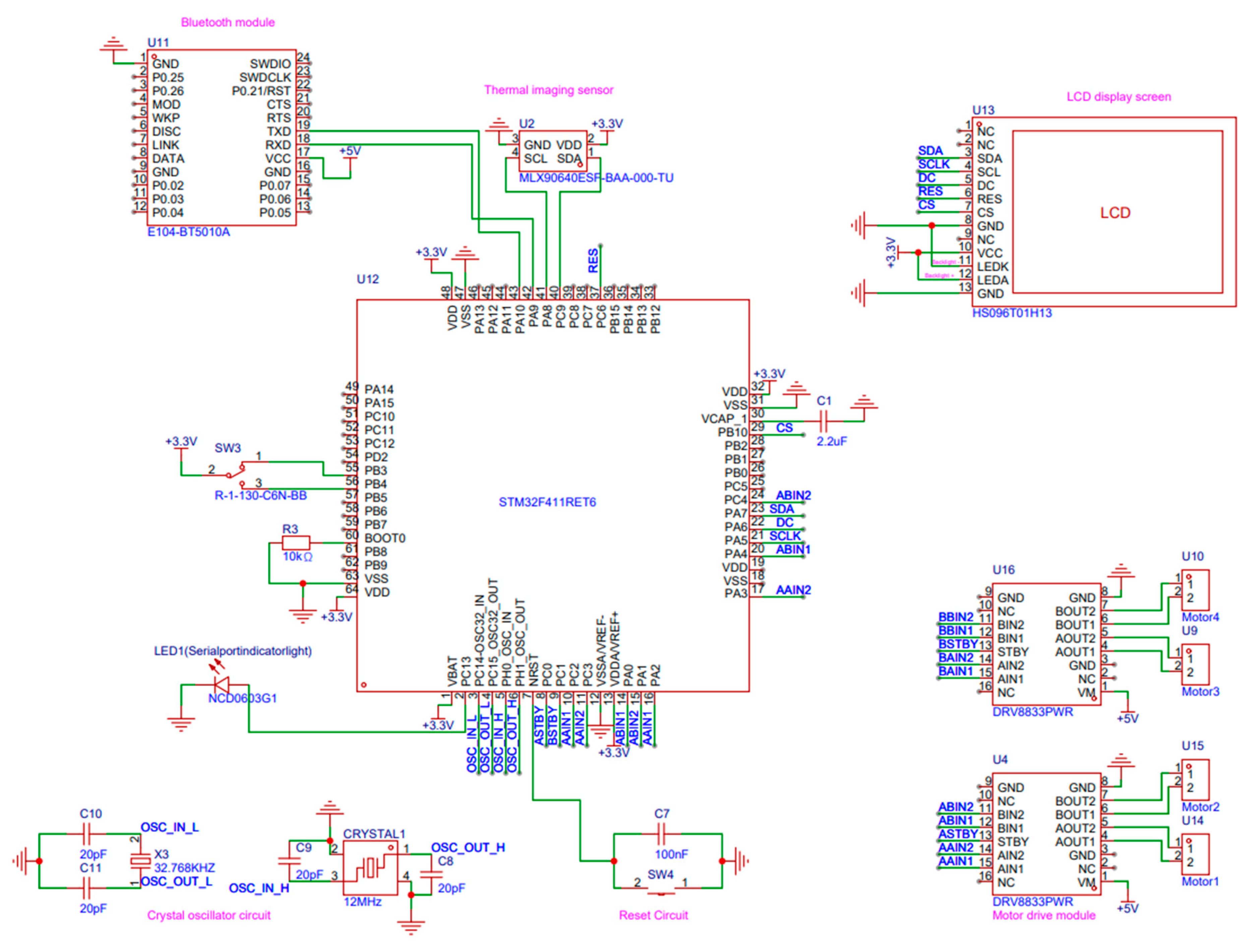
As shown in
Figure 2, the diagram shows the circuit wiring principle of this study, and clarifies the corresponding modules and functions of each pin of the main control chip.
2.2. Hardware Design for Independent Thermal Imaging Gesture Control
2.2.1. Hardware Design Overview
This design presents a physical prototype featuring three operational modes selectable via a boat-type switch. The first mode exclusively recognizes gestures and displays them on an LCD screen. The second mode not only recognizes and displays gestures but also drives the robotic platform based on the recognition outcomes. The design employs the STM32F411RET6 as the main control chip, powered by a single 18,650 lithium battery. A neural network trained using Python with the Keras framework is ported to the microcontroller. As shown in
Figure 3, when the boat-type switch connected to the microcontroller is toggled to Mode 1, the MLX90640 thermal imaging sensor transmits thermal data to the microcontroller. The microcontroller then processes this data to recognize gestures, displaying the thermal image, the highest and lowest temperatures within the thermal range, and the recognized gesture results on the LCD screen. Concurrently, it controls the movement of the mobile robot based on the recognition results. The design utilizes the DRV8833 motor driver module, which lacks PWM speed control functionality. To enhance the robot’s adaptability to various environments, a Bluetooth module is incorporated. Switching the boat-type switch to Bluetooth mode allows the mobile robot’s movement states to be controlled via a smartphone app connected to the Bluetooth module. The mobile robot’s movement is facilitated by four N20 geared motors driving four Mecanum wheels, arranged in an X-pattern on the platform, enabling omnidirectional movements including forward, backward, leftward, and rightward translations. The hardware models used in this design and their main parameters are listed in
Table 2.
2.2.2. LCD Screen
In this project, the liquid crystal display (LCD) serves the purpose of presenting thermal imaging visuals alongside the recognition outcomes processed by the microcontroller [
30]. The design incorporates the HS096T01H13 LCD module.
Figure 4 illustrates the circuit diagram of the LCD adapter board, detailing the functionality of the eight pins as follows: The CS (Chip Select) pin is utilized to designate the LCD as the target device for communication by transmitting control signals. The VCC pin supplies power to the screen, connected to a 3.3V source. The SCK (Serial Clock) pin, integral to the SPI (Serial Peripheral Interface) communication protocol, facilitates the transmission of clock signals. The SDA (Serial Data Line) pin, also part of the SPI protocol, is responsible for data transmission. The DC (Data/Command) pin determines whether the transmitted signal is interpreted as data or a command; a low signal indicates a command, while a high signal signifies data. The RST (Reset) pin, active low, initiates a reset of the LCD to its initial state upon receiving a specific level signal. The GND (Ground) pin provides the grounding for the screen. Lastly, the LEDK pin controls the backlight brightness of the LCD, enabling the adjustment of backlight illumination through level modulation.
2.2.3. MLX90640 BAA Type Thermal Imaging Sensor
The operational principle of the MLX90640 is grounded in the theory of blackbody radiation, which posits that the intensity of infrared radiation emitted by an object increases with its temperature. This sensor employs a 24 × 32 pixel array detector to capture the infrared radiation emitted by objects, subsequently converting this radiation into digital signals. These digital signals are then read and processed to derive temperature information from the objects. The array comprises numerous minute infrared detection units, each capable of measuring the infrared radiation intensity of a specific area. By assessing the infrared radiation across different regions, the sensor constructs a thermal imaging representation of the entire scene [
31].
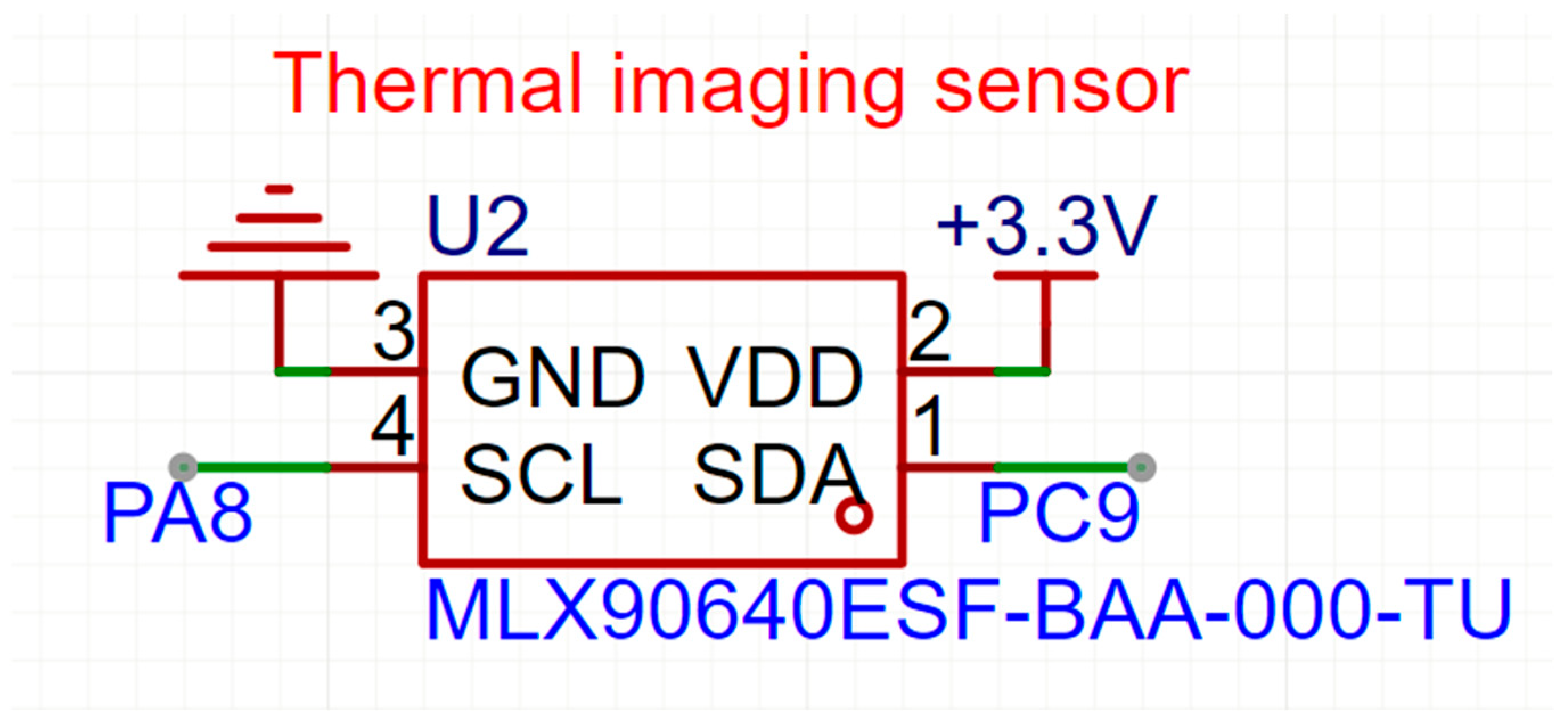
As shown in
Figure 5,the SCL pin of this sensor serves as the clock signal pin for the I
2C bus, connecting to the I
2C bus clock pin of the microcontroller. The microcontroller facilitates data transmission by generating clock pulses on the SCL pin. The SDA pin, functioning as the data signal pin for the I
2C bus, is utilized for data exchange between the microcontroller and the sensor. Under the control of clock pulses on the SCL pin, the sensor transmits temperature data to the microcontroller via the SDA pin.
2.2.4. E104-BT5010A Bluetooth Module
In this design, the baud rate of the microcontroller’s serial port is configured to 115,200, whereas the E104-BT5010A Bluetooth module is factory-set to a baud rate of 9600. Consequently, it is necessary to initially connect the module’s serial port to a computer via a USB-TTL module and utilize serial port assistant software to input AT commands to alter the Bluetooth module’s baud rate [
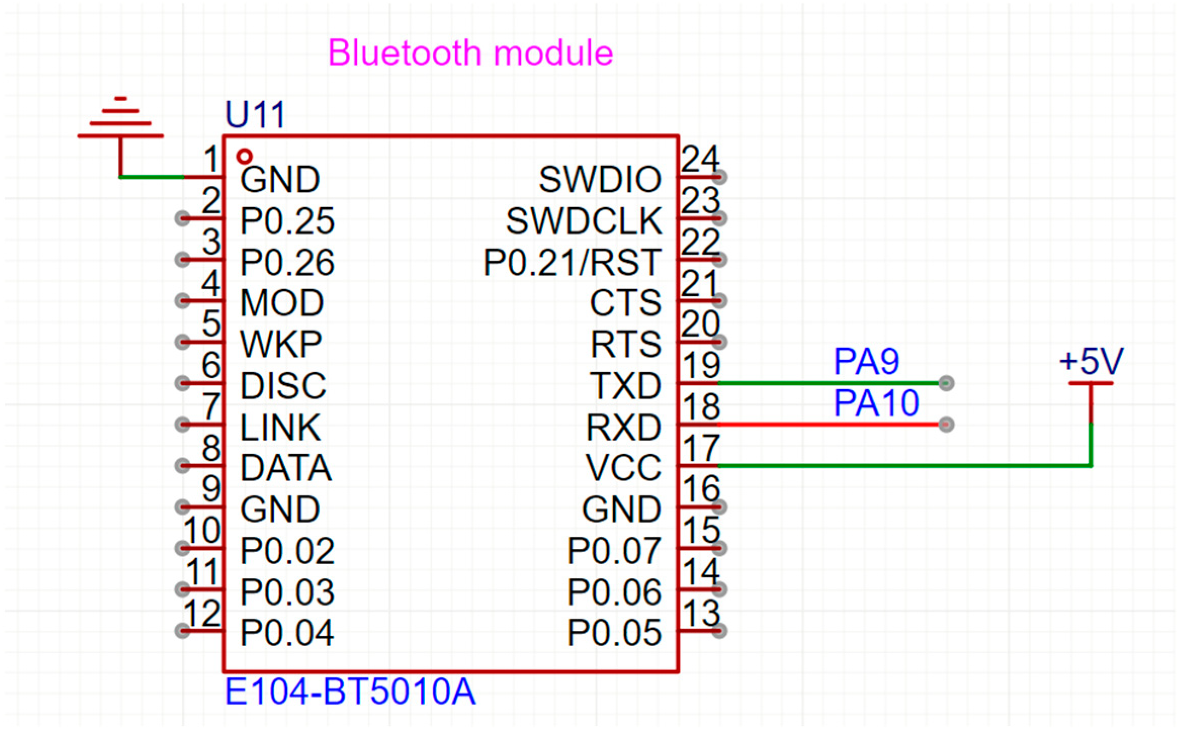
32].
Figure 6 shows how to wire the pins of the Bluetooth module. For data transmission using the Bluetooth module, the VCC pin of the module is supplied with 5 V, and the GND pin is grounded. The RXD pin of the Bluetooth module is connected to the TXD pin of the microcontroller, and the TXD pin of the Bluetooth module is connected to the RXD pin of the microcontroller. The official smartphone application provided by Daxia Longque is then used to connect to the Bluetooth module and transmit data to it, which the Bluetooth module subsequently relays to the microcontroller via the serial port.
2.2.5. DRV8833 Motor Driver Module
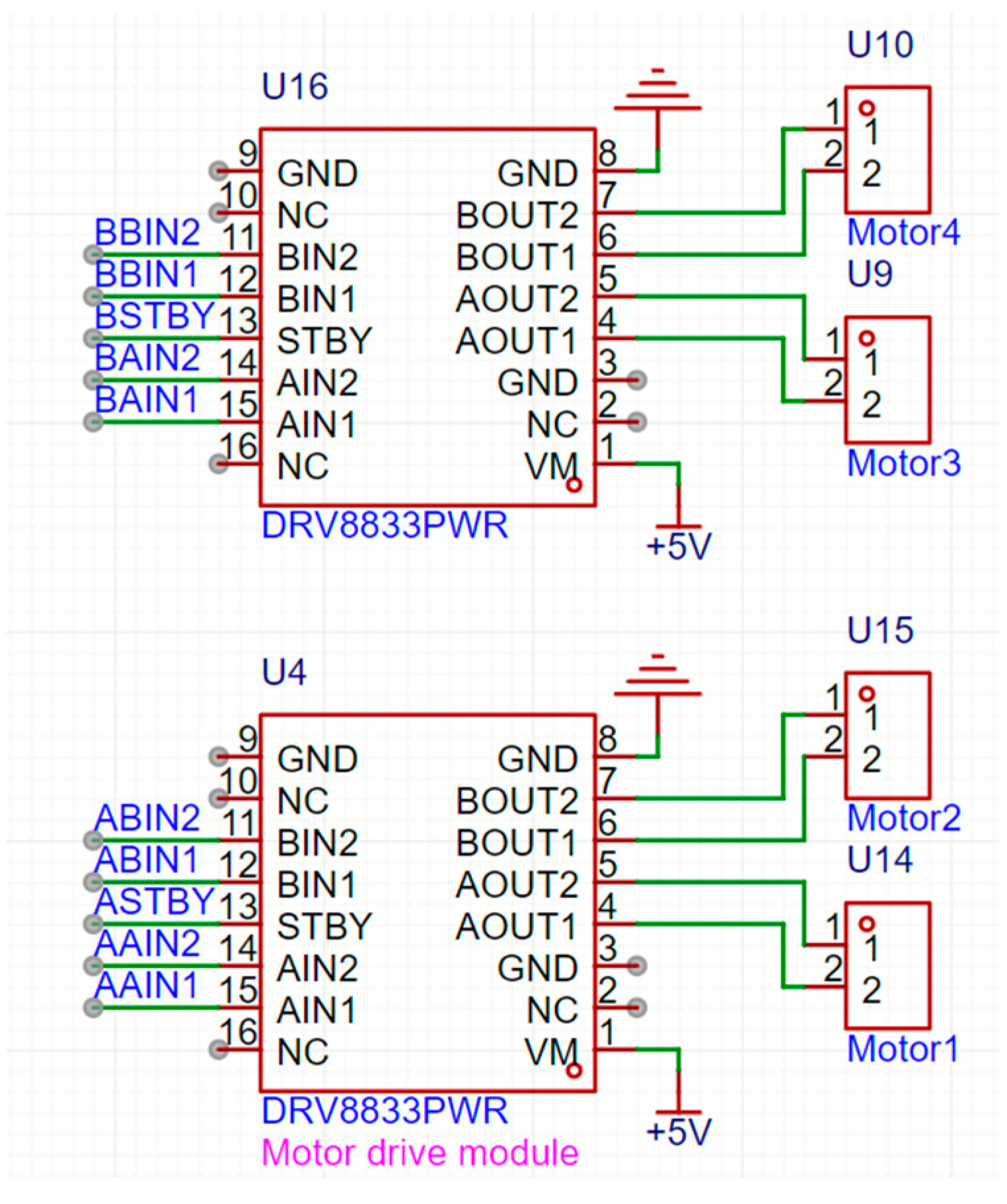
In
Figure 7, the pin diagram of the DRV8833 motor driver module is presented. The AIN1, AIN2, BIN1, and BIN2 pins are connected to the IO ports of the microcontroller. The AO1, AO2, BO1, and BO2 pins are respectively connected to the positive and negative terminals of two DC motors, with the high and low level outputs from the microcontroller’s IO ports controlling the forward and reverse motion of the motors. The STBY pin is connected to a high-level output pin of the microcontroller to ensure normal operation of the motors. The VM pin, serving as the power supply pin for both the module and the motors, can accommodate a voltage range of 2.7 to 10 V. In this design, the driving voltage for the DC motors is set at 3V. Given that the microcontroller only provides 3.3 V and 5 V power outputs, the VM pin of this module is supplied with a 3.3 V voltage in the context of this design.
2.3. Design of Software for Independent Thermal Imaging Gesture Control
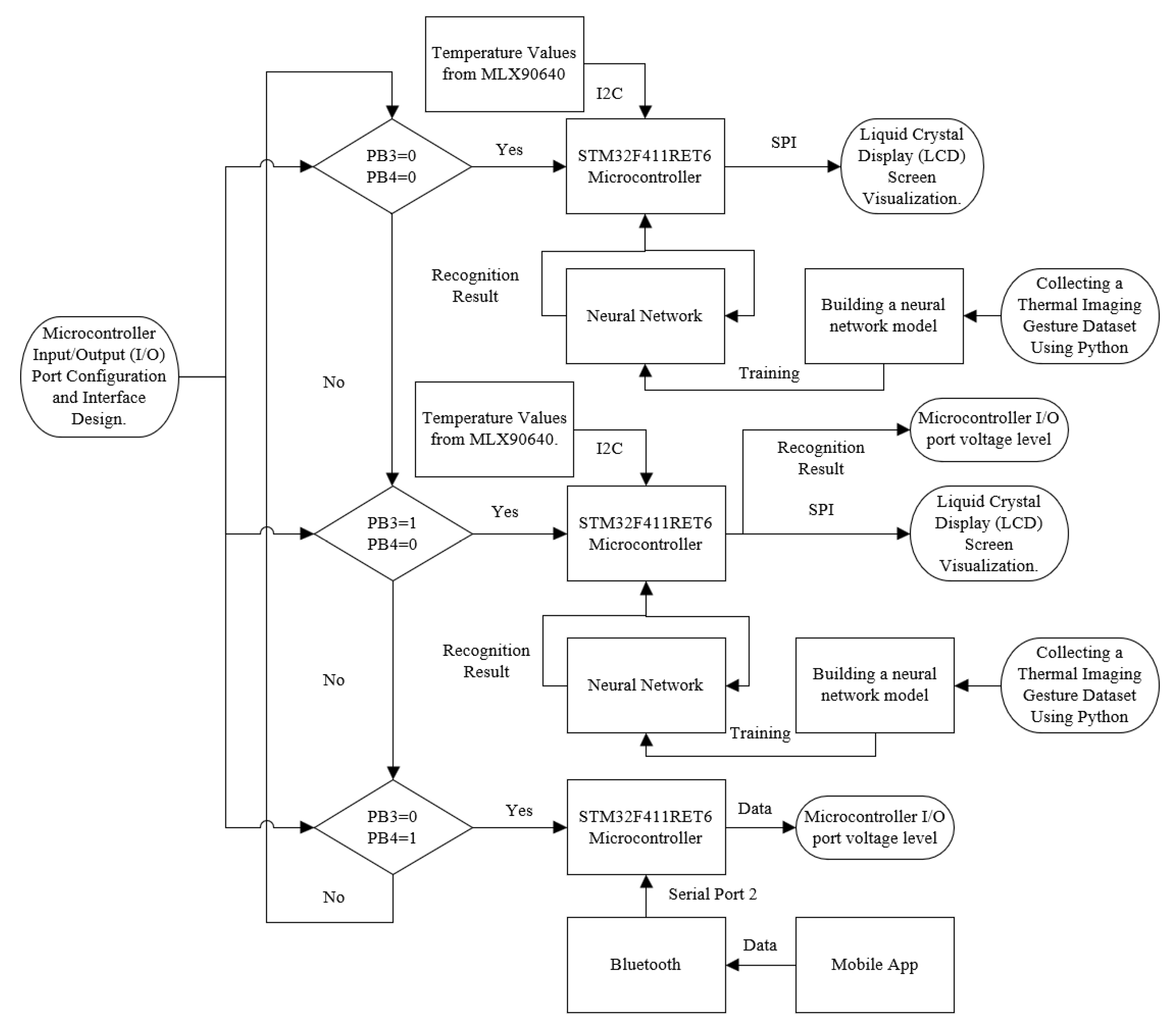
As depicted in
Figure 8, the software flowchart of the design is presented. The design initiates with the STM32F411RET6 microcontroller driving the MLX90640 thermal imaging sensor to capture thermal images, which are then displayed on the LCD screen. Concurrently, the temperature data of the 24 × 32 pixel points from the thermal image are transmitted to a computer via a serial port. The computer utilizes Python to store the temperature data in an array, creating a dataset. Subsequently, Python employs this dataset to train a neural network within the Keras framework. The trained neural network is then ported to the STM32 program using the CubeAI feature in the STM32CubeMX software.
Within the STM32 program, the microcontroller acquires temperature data from the MLX90640 thermal imaging sensor via the I2C bus. This temperature data is then mapped to a 0–255 RGB color space. The microcontroller transmits the hexadecimal color values of each pixel to the LCD screen for display through the SPI bus. The ported neural network is utilized by the microcontroller to recognize gestures from the thermal images, and based on the recognition results, it controls the IO port levels connected to the signal input pins of the motor driver chip, thereby managing the platform’s movement state.
When both input pins PB3 and PB4 of the microcontroller are set to 0, the microcontroller executes a program solely for gesture recognition and image display. When PB3 is set to 1 and PB4 to 0, the microcontroller executes a program that includes gesture recognition, image display, and IO port level output. When PB3 is set to 0 and PB4 to 1, the microcontroller executes a program for serial data reception and IO port level output, operating in Bluetooth mode. In Bluetooth mode, a smartphone app connects to the Bluetooth module and sends data to it. Upon receiving the data, the Bluetooth module transmits it to the microcontroller via Serial Port 1. The microcontroller then adjusts the IO port levels connected to the signal input pins of the motor driver chip based on the received data, thereby altering the platform’s movement state.
2.3.1. Design of Keil Program for Data Acquisition
The flowchart of the program design for this section is illustrated in
Figure 9. The MLX90640 thermal imaging sensor captures temperature values from a 24 × 32 pixel array and transmits these values to the STM32F411RET6 microcontroller via the I2C bus. The microcontroller then extrapolates the 24 × 32 pixel data from the thermal imaging sensor to fit the 135 × 240 pixel resolution of the LCD screen. It maps the received temperature values to a color scale ranging from 0 to 255 and sends the color data to the LCD screen for display through the SPI bus. Simultaneously, the microcontroller transmits the 24 × 32 temperature values of a single thermal image to a computer via Serial Port 1, where these temperature data are processed and stored.
2.3.2. Design of Python Programs for Data Collection and Neural Network Training
The flowchart illustrated in
Figure 10 delineates the process of saving arrays and training a neural network using Python. Initially, Python stores the data received from the serial port as arrays, then constructs a neural network model, and subsequently trains and outputs the neural network using the stored arrays. When Python receives data from the serial port, it first configures the serial port settings to ensure the baud rate matches that of the lower-level machine. Two arrays are then defined: one to store the temperature values of the 24 × 32 pixel points of the image, and another to store the labels corresponding to each image. A total of 50 image data sets are intended to be received. The process of populating the arrays with data is omitted here, and finally, the collected data is saved in an NPZ format file. The NPZ file, a binary format specific to NumPy, is utilized for storing and transmitting large volumes of numerical data and can contain one or more NumPy arrays. As a file storage format within the NumPy library, NPZ files effectively reduce file size, conserve storage space, and facilitate the organization, management, and cross-platform sharing of data. In the realms of scientific computing and data analysis, using NPZ files allows for the convenient storage of data within a single file, enabling the retrieval and reading of array data by name, thereby enhancing the efficiency and flexibility of data processing. In this design, the file stores a two-dimensional array for image temperature data and a one-dimensional array for label values. After collecting a sufficient number of image data, all NPZ files containing the data are merged into one, which is then saved as a new NPZ file.
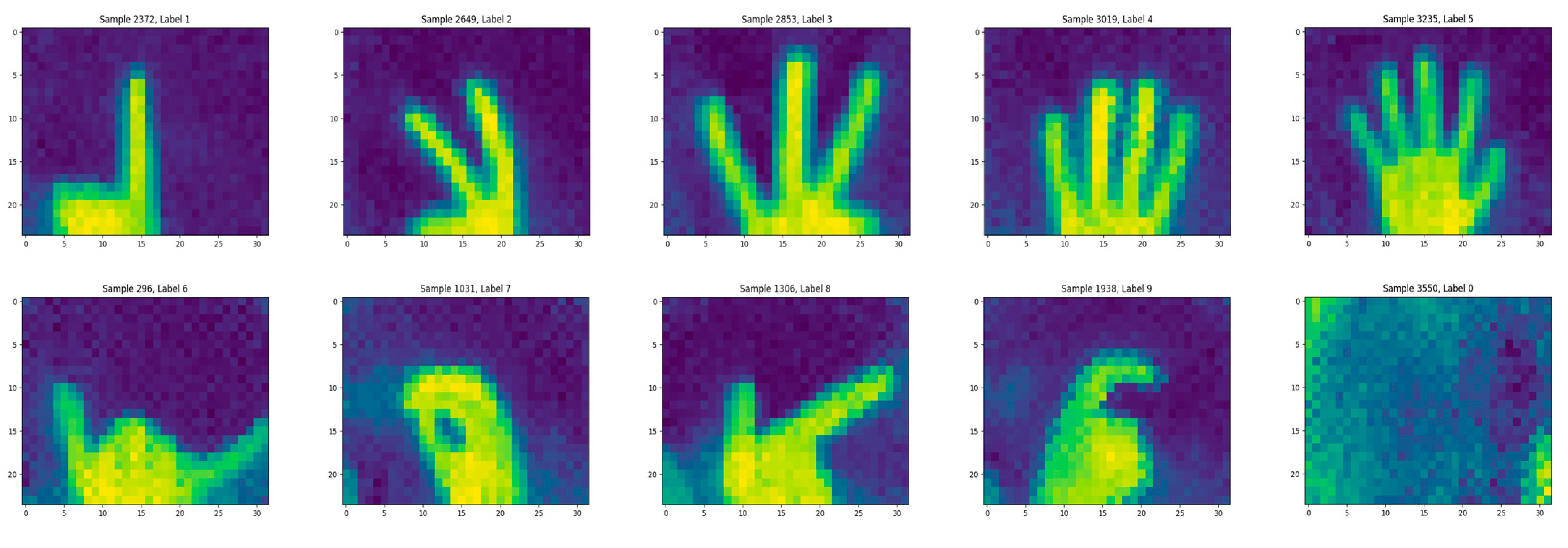
As shown in
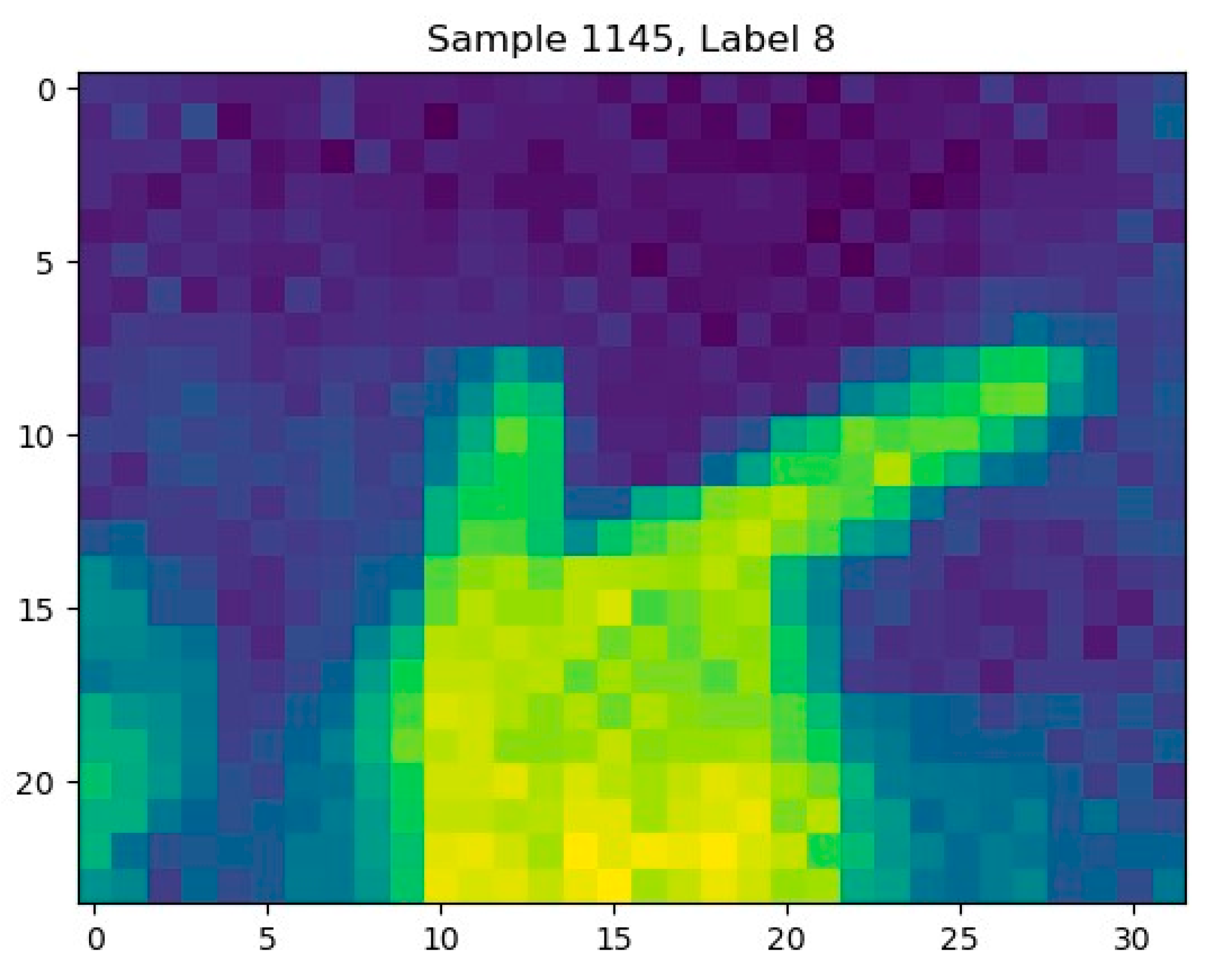
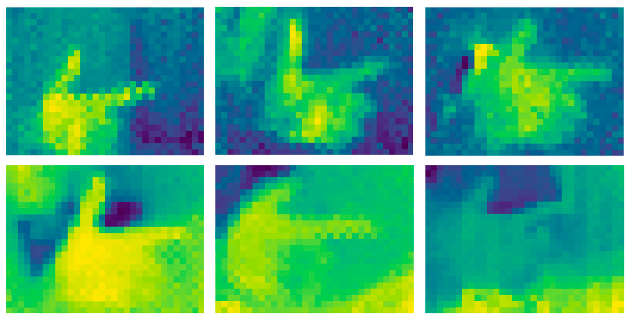
Figure 11, this is an example diagram of the visualization of the collected temperature data. The dataset contains 10 categories (corresponding to gestures 0–9), with a total of 7073 thermal imaging images. Each gesture category has approximately 500 to 900 images collected. The number of arrays for various gestures is listed in
Table 3.Through Python programs, temperature data is stored as arrays and used to create datasets. When collecting thermal imaging gesture data using Python, the corresponding labels are recorded synchronously while storing temperature data as arrays. When merging datasets, the one-to-one correspondence between images and labels is maintained. These datasets are used to train Keras-based neural network models. The study trained the model using collected raw data without employing data augmentation to improve the reliability of model training.
Upon completion of the dataset merging, the neural network can be trained using the dataset. After loading the NPZ dataset, the arrays within the dataset are extracted, and the temperature data undergoes normalization followed by dimensionality transformation to convert the images into grayscale. A Keras neural network model is then constructed. This neural network model is built layer by layer in sequence, with the output of one layer serving as the input to the next. It comprises two convolutional layers, two pooling layers, and three fully connected layers. The first convolutional layer is configured with 30 convolutional kernels, equating to 30 output channels, each with a size of 3 × 3, and does not perform edge padding on the image, meaning the boundary parts of the input data are not covered by the convolutional kernels. The ReLU function is used as the activation function, and the input image is a 24 × 32 pixel grayscale image. This convolutional layer functions to extract features from the input image. Through convolutional operations and the activation function, it transforms the input data into a higher-dimensional feature representation, facilitating better processing for subsequent classification or other tasks. The second convolutional layer is similar, only altering the number of convolutional kernels. The first pooling layer sets the pooling window size to 2 × 2 and performs edge padding to maintain the output dimensions identical to the input. The second pooling layer follows suit. Subsequently, the multi-dimensional feature maps are flattened into a one-dimensional vector. Flattening occurs after the pooling layers, aiming to compress the information extracted from the feature maps into a vector, which is then fed to the fully connected layers for classification tasks. The first two fully connected layers are configured with 40 and 20 neurons, respectively, and utilize the ReLU (Rectified Linear Unit) as the activation function, which returns the input value when it is greater than zero and returns zero otherwise. The final fully connected layer is set with 10 neurons and employs the Softmax function as the activation function, converting the neuron outputs into a probability distribution, with each neuron corresponding to one of the gestures from 0 to 9. Using Softmax as the activation function ensures that each neuron in the output layer outputs a probability value, summing up to 1, thereby representing the probability of the input image belonging to each gesture category. The training is set to 50 epochs, with the batch size for updating model parameters in each training iteration set to 64, and the learning rate set to 0.001. Finally, the training commences, and the model is saved as a neural network in H5 format.
In
Figure 12, the architecture of the neural network is presented, constructed in a sequential manner where the output size of each layer serves as the input for the subsequent layer. The purpose of setting convolutional kernels is to scan the image row by row and column by column, extracting feature values from each small region of the image. The formula for calculating the output image width of the convolutional layer is shown in Equation (1), the output image height in Equation (2), and the number of output image channels in Equation (3). The input image dimensions for the convolutional layer are (W, H, D), the number of convolutional kernels is N, the size of each convolutional kernel is (a, b), p is the padding number (p is 0 when no padding is applied), and S is the stride, which is the distance the convolutional kernel moves when scanning the image. If not set, the default stride is 1, both horizontally and vertically. The formula for calculating the output image width of the pooling layer is shown in Equation (4), the output image height in Equation (5), and the number of output image channels in Equation (6). The window size of the pooling layer is (c, d), the input image dimensions are (W, H, D), and S is the stride. If not set, the default stride is the width and height of the pooling layer window. According to the formula, the input image dimensions for the first convolutional layer of the neural network are (24, 32, 1), the number of convolutional kernels is 30, the convolutional kernel size is (3, 3), the padding mode is set to no padding, and the default stride is 1. The window size of the first pooling layer is set to (2, 2), and since the stride is not set, it defaults to the pooling layer window size, meaning both horizontal and vertical strides are 2. Therefore, the calculated output image dimensions of Pooling Layer 1 are (11, 15, 30), which serve as the input for the second convolutional layer. Consequently, the input image dimensions for the second convolutional layer are set to (11, 15, 30). At last, the hyperparameters used in the model training process are shown in
Table 4.
Additionally, the parameters of each layer of the neural network are listed in
Table 5, the ReLU activation function is used in both the convolutional layers and the fully connected layers. A neural network requires a nonlinear activation function to learn complex patterns and features. The ReLU function can introduce nonlinear factors into the network, enabling the network to learn complex nonlinear relationships in the input data and thereby enhancing the model’s expressive ability. For example, in the convolutional layers, ReLU helps extract features such as gesture contours, and in the fully connected layers, it assists in feature fusion and dimensional transformation. The Softmax activation function is used in the output layer. This neural network is used for gesture classification, and the Softmax function can convert the output values of the neurons in the output layer into a probability distribution. It maps the output value of each neuron to between 0 and 1, and the sum of the output values of all neurons is 1, so that the output result can be directly interpreted as the probability corresponding to each gesture category.
2.3.3. Transplanting Neural Networks and Architecting Keil-Based Firmware
Shown in
Figure 13 is the flowchart of the STM32 program for the design. First, the microcontroller detects the voltage levels of two input pins to determine the mode. When both input pins are at a low voltage level, the neural network is used to recognize gestures, and the image and recognition results are displayed on the LCD screen. When pin PB3 is at a high voltage level and pin PB4 is at a low voltage level, the neural network recognizes gestures and displays the results while controlling the voltage levels of the output pins based on the recognition results to control the movement of the platform. When pin PB3 is at a low voltage level and pin PB4 is at a high voltage level, the microcontroller receives data from the serial port and controls the voltage levels of the output pins based on the received data. After the neural network training is completed, INT8 quantization is used to optimize the model on embedded devices such as STM32, and the main purposes are to significantly reduce memory usage, improve computing speed, and lower power consumption. The neural network needs to be ported to the STM32 code using the X-CUBE-AI tool in the STM32Cube-MX software. After selecting the neural network, it is first analyzed. The analysis shows that the neural network occupies 411.78 KB of the microcontroller’s flash memory and 83.84 KB of the microcontroller’s RAM. The STM32F411RET6 microcontroller has a total flash memory capacity of 512 KB and a total RAM capacity of 128 KB. After analysis, the neural network is verified, and the final output is a file that can be compiled by the MDK compiler.
2.3.4. Design and Development of Android-Based Mobile Application Software
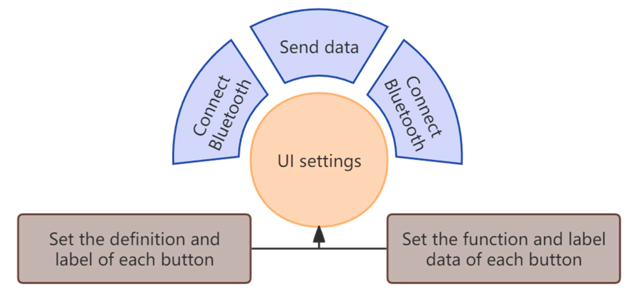
In
Figure 14, the flowchart for designing the Android application is presented. The process initiates with the design of the software interface, followed by the configuration of button functionalities. These functionalities encompass connecting to Bluetooth, disconnecting from Bluetooth, displaying Bluetooth information, transmitting data, and setting up label displays, primarily to indicate the Bluetooth connection status and related information.
The logic of Bluetooth control has been outlined in
Section 2.1, and it is elaborated in detail here. When the toggle switch is set to the corresponding position where PB3 is low and PB4 is high, the STM32F411RET6 microcontroller enters the Bluetooth control mode. In this state, the thermal imaging sensor and LCD screen are deactivated. The Bluetooth module connects to the microcontroller via a serial port, with its baud rate adjusted from the default 9600 to 115,200 using AT commands to match the microcontroller’s serial communication settings. Once the mobile app pairs with the Bluetooth module, it sends pre-set control commands. The module transmits these commands to the microcontroller through the serial port. The microcontroller then interprets the commands and outputs corresponding level signals via its GPIO pins. These signals drive the DRV8833 motor driver module and N20 geared motors, enabling the robot car to perform movements such as forward, backward, left shift, right shift, and stopping.
Controlling the car’s movement through mobile phone Bluetooth, in most cases, mainly involves the mobile phone sending control instructions to the car, and the car receives the data to realize the movement control of the car. At this time, the car can complete basic control functions without sending information to the mobile phone. In some scenarios, the car sending information to the mobile phone can bring a more complete interactive experience and enhance the user’s perception and control of the car’s state.
3. Results
3.1. Results of the Design
In
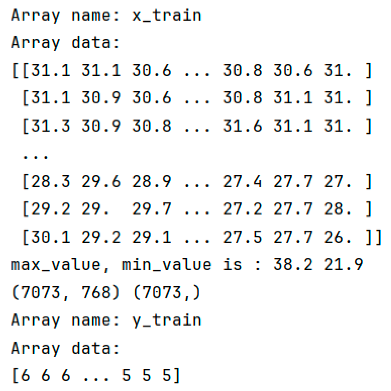
Figure 15, the data within the array file storing thermal imaging gesture data is displayed. It is observable that the x_train array contains 7073 arrays, each with a length of 768 data points. These 768 data points correspond to the temperature values of the 24 × 32 pixel points captured by the MLX90640 thermal imaging sensor, amounting to a total of 7073 sets of temperature data, or equivalently, 7073 thermal imaging images. The y_train array stores the labels corresponding to each image in the x_train array. In
Figure 16, one of the images with a gesture label of 8 is presented when converting the data from the array into an image.
In
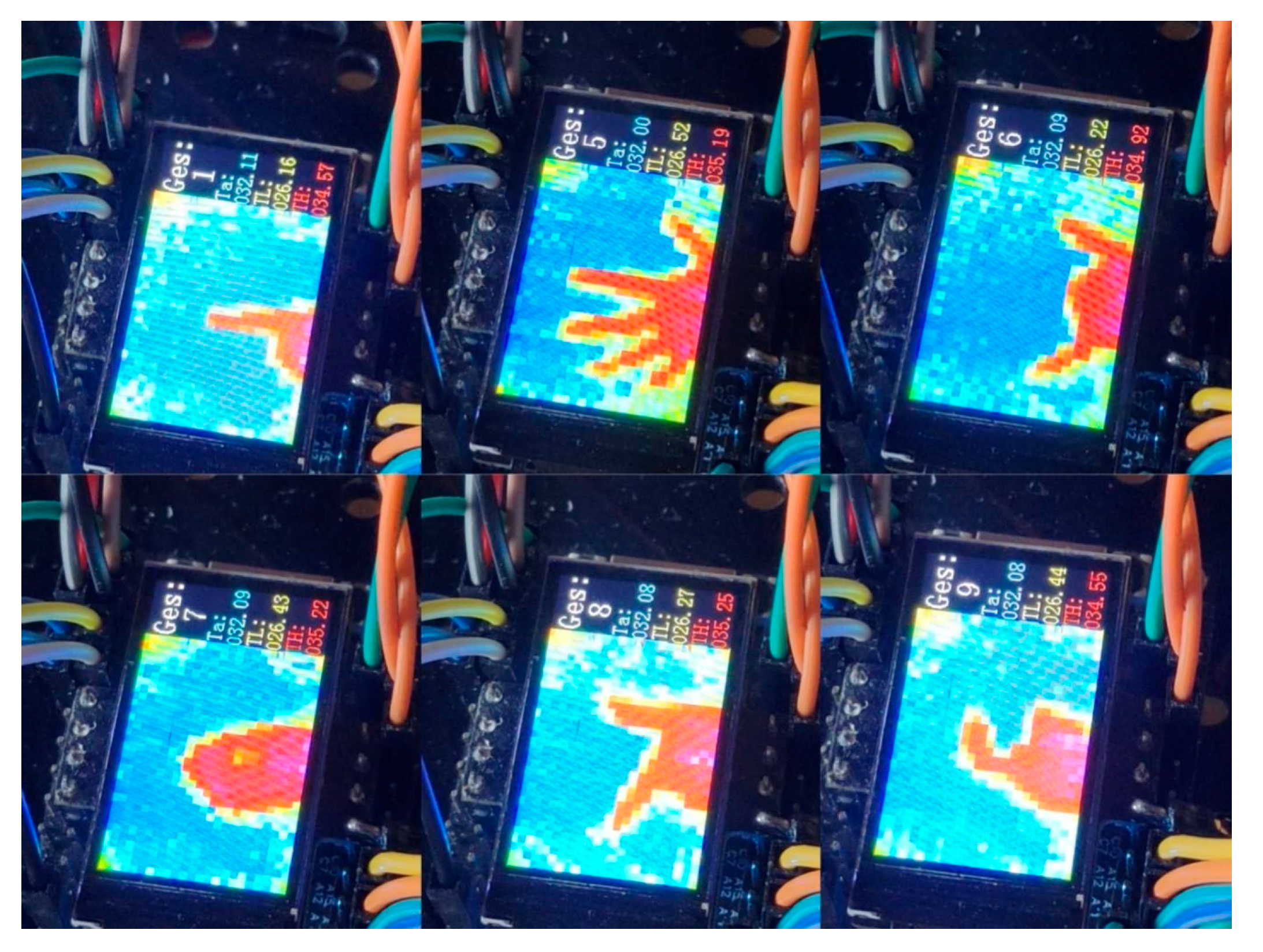
Figure 17, the results of thermal imaging gesture recognition in this design are displayed. The left section of the screen showcases the thermal imaging image, while the right section presents the recognized gesture in white font labeled as “Ges”, the sensor’s casing temperature in blue font labeled as “Ta”, the lowest temperature within the sensor’s measurement area in yellow font labeled as “TL”, and the highest temperature within the sensor’s measurement area in red font labeled as “TH”. When the boat-type switch is toggled to Mode 1, the microcontroller can also control the movement state of the mobile robot based on the gesture recognition results.
The design of thermal imaging sensor-based gesture control utilizes a microcontroller to recognize thermal imaging gestures captured by the thermal imaging sensor, enabling autonomous operation without the need for a computer. However, since thermal imaging gesture recognition relies on the contour shape of the hand, it requires the hand to be positioned at a specific angle in front of the sensor. The Bluetooth control scheme serves as an alternative option when gesture control malfunctions.
Figure 18 shows the display of the designed Android app when used. The upper button is used to connect, disconnect, and view information from the Bluetooth module. The button below sends characters to the Bluetooth module, which correspond to the data in the microcontroller program to control the platform’s motion status.
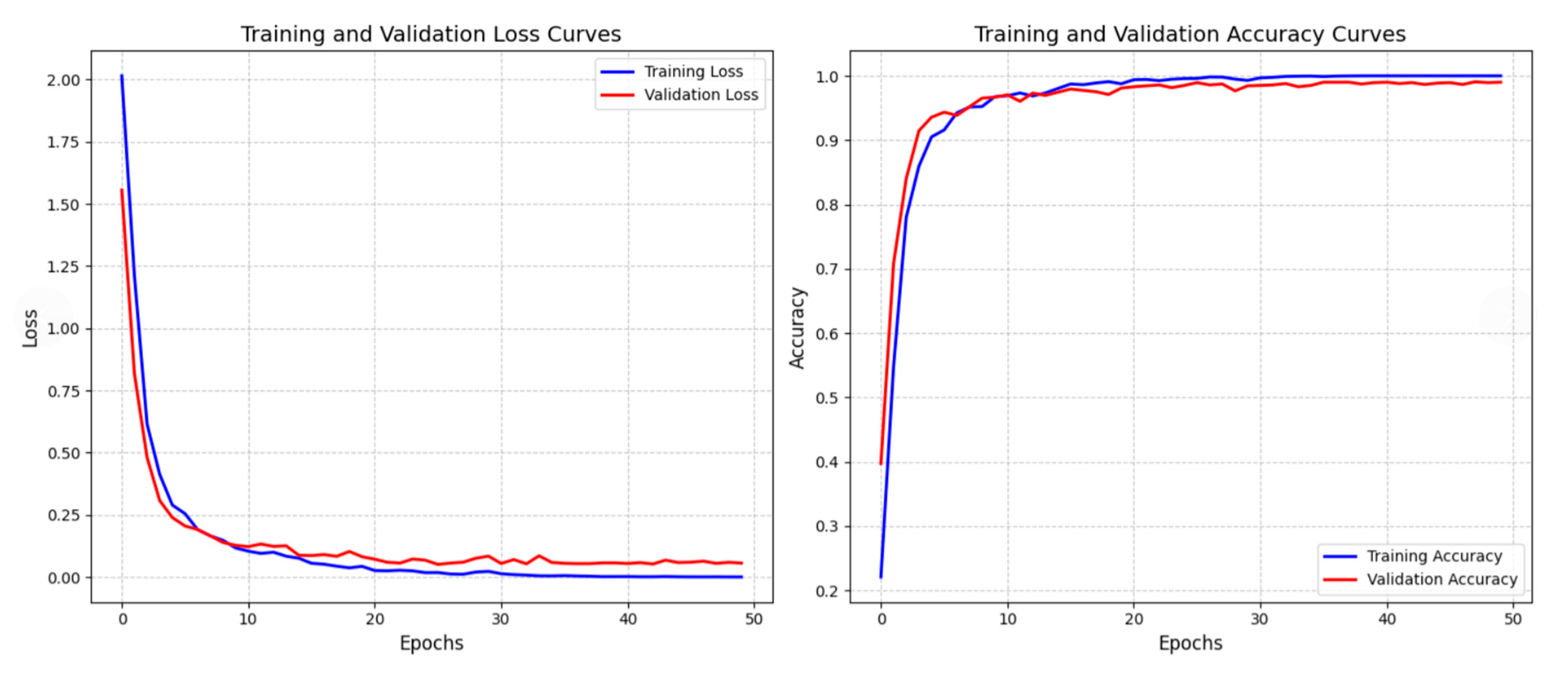
Figure 19 presents the trend of loss and accuracy changes between the training set and validation set during the model training process. The left figure shows the loss curve, and both the blue training loss and the red validation loss decrease rapidly with increasing training epochs (epochs) before stabilizing. The right figure shows the accuracy curve. The blue training accuracy and red validation accuracy quickly increased in the early stage and remained stable afterwards, and the loss and accuracy curves of the training set and validation set showed similar trends. The training results show that the model’s loss continues to decrease, and its accuracy steadily improves on both the training and validation sets with similar performance. After 50 epochs of training, the model achieves an accuracy of 99.05% and a loss value of 0.05. This indicates that the model’s learning is effective, with good generalization ability and certain robustness.
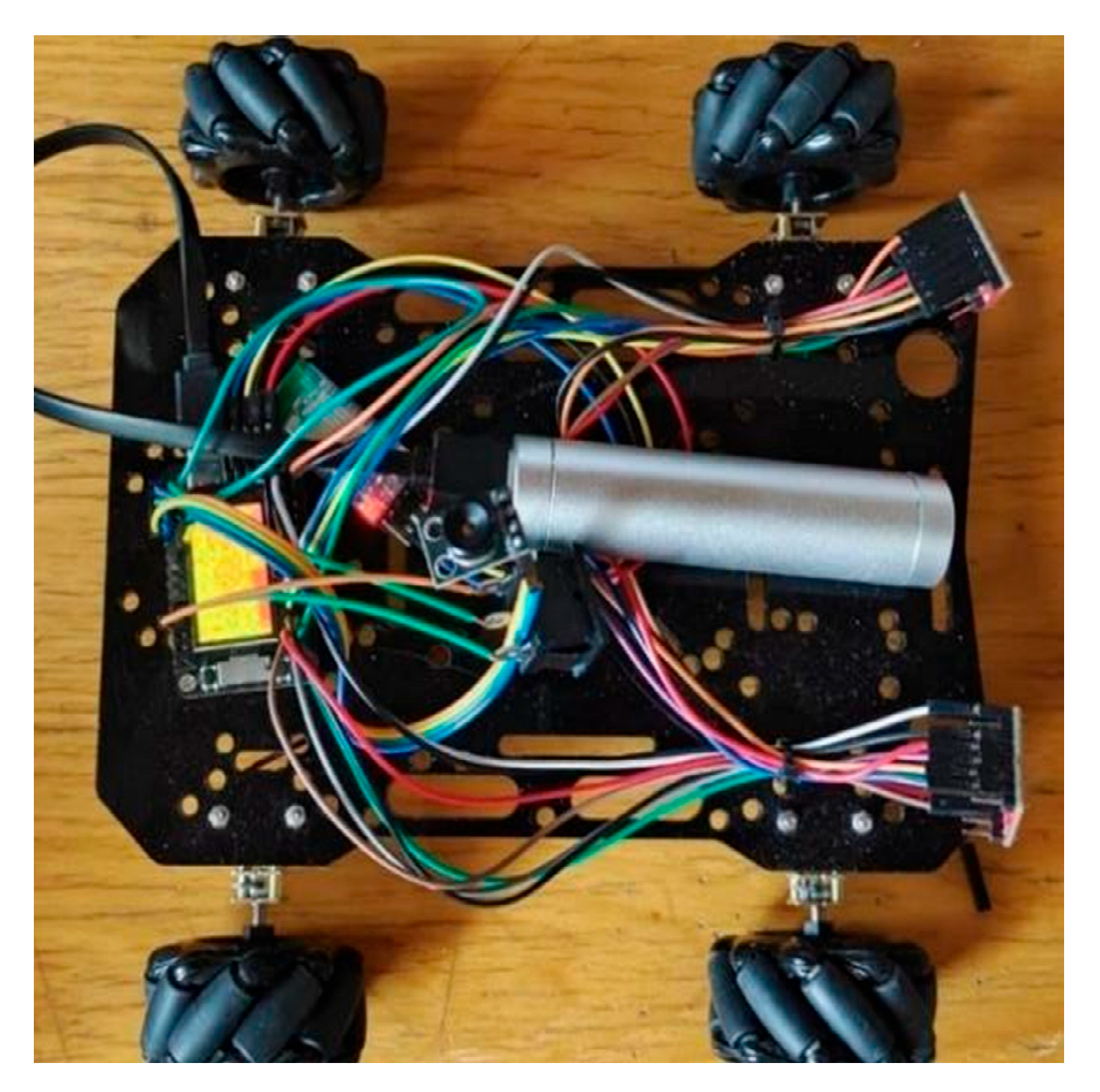
Figure 20 shows a physical car we designed, equipped with the aforementioned neural network. Through the recognition of gestures by the thermal sensor on it, we can control the car’s forward, backward, and turning movements. The system corresponds to nine gestures and a default state of empty recognition. Gestures and corresponding functions are listed in
Table 6.Only five of these gestures are used in the car’s design. The unshown gestures are reserved for future function expansion or may be used in more complex scenarios, such as smart homes.
3.2. Comparison of Accuracy Between Thermal Imaging Recognition and RGB Camera Recognition
To conduct a comparison, the CNN framework provided by the Edge Impulse platform was employed to train an RGB gesture recognition model. The training set comprised 580 gesture images captured under varying brightness conditions, with a training-to-test set ratio of 8:2. The different brightness conditions are shown in
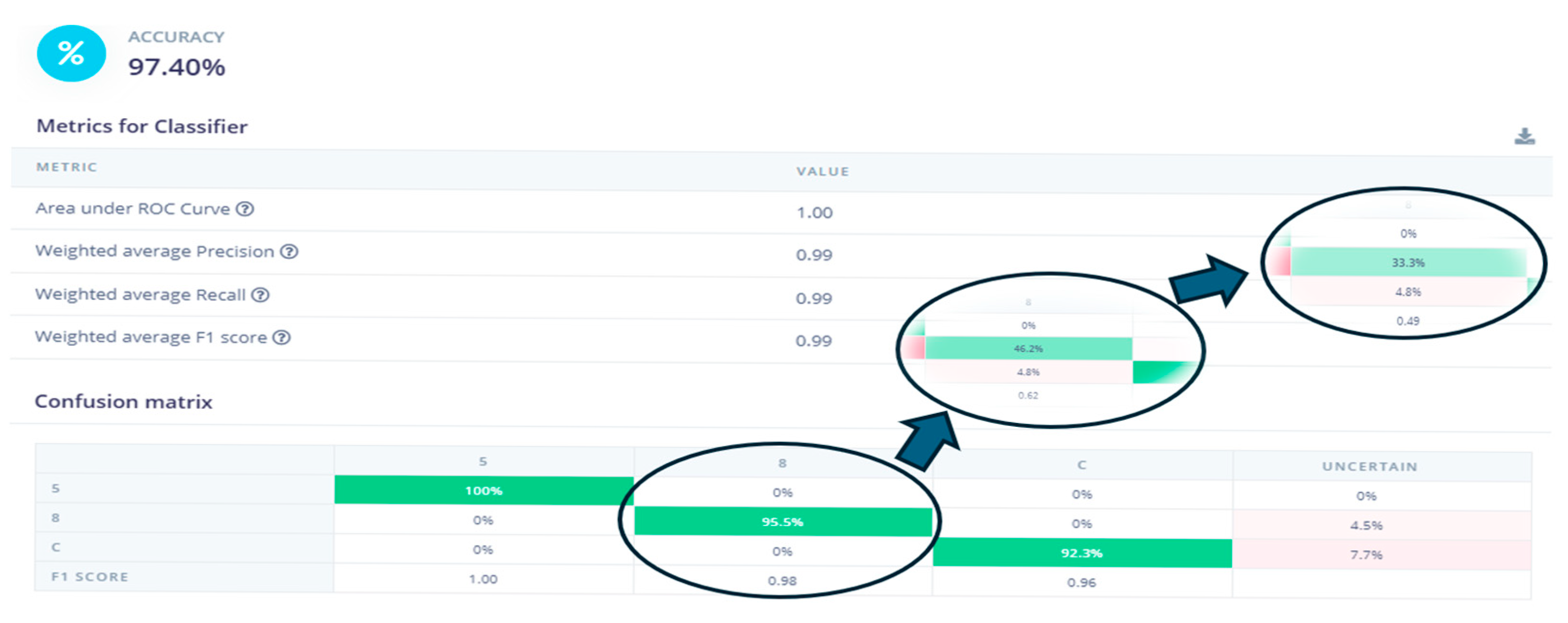
Figure 21. The learning rate was set to 0.005, and the number of training epochs was 50. This model was designed to recognize three primary gestures, “5”, “8”, and “C”, facilitating a comparison with thermal imaging-based gesture recognition. The test set for gestures “5” and “C” consisted of images captured under normal lighting conditions. Following model training, images of gesture “8” captured under various lighting conditions were incorporated into the test set for evaluation.
As shown in
Figure 22, all test samples were selected from gestures captured under normal lighting conditions. The results showed that all three gestures achieved high accuracy.
Next, the test set for gesture “8” was modified by replacing it with 57 images captured under low-light conditions, while the training sets for gestures “5” and “C” remained unchanged under normal lighting. The test results indicated that the recognition accuracy for gesture “8” decreased to 46.2%.
Finally, the dataset for gesture “8” was replaced with 51 images acquired in complete darkness, with the training sets for gestures “5” and “C” retained under normal lighting conditions. The test results demonstrated a further decline in the recognition accuracy for gesture “8”, dropping to 33.3%.
Through the comparison in
Table 7, it can be seen that the core advantage of thermal imaging recognition lies in its use of “heat” as the core feature, which frees it from dependence on ambient light. In contrast, RGB recognition is limited by the physical properties of visible light and struggles to work stably in complex lighting or harsh environments.
3.3. Comparison of Thermal Imaging Recognition Accuracy Under Different Temperatures and Scenes
In the comparative experiment between thermal imaging recognition and RGB recognition, this study also measured the accuracy of thermal imaging recognition under different temperatures and scenarios. The data collection was conducted in an empty indoor environment at a normal temperature of 26 ℃. On this basis, two other common scenarios were additionally selected, as shown in
Figure 23. The first scenario includes corridors, offices, and dormitories with interference from other heat sources at a temperature of 30 ℃ (arranged from left to right in the first row of the figure). The other scenario is an outdoor environment under direct sunlight with a local temperature of 36 ℃. The data was collected at 2:38 p.m. on 26 July at the Huayuan Campus of North China University of Water Resources and Electric Power, Jinshui District, Zhengzhou City, Henan Province, China.
In this study, 300 sets of gesture 8 data were prepared for corridors, offices, and dormitories with interference from other heat sources at a temperature of 30 °C, and 50 sets of gesture 8 data were prepared for outdoor environments under direct sunlight at a temperature of 36 °C. The neural network described in
Section 2.3.2 was used for testing, and the test results are shown in the following
Figure 24.
As shown by the above results, compared with the accuracy of 0.9905 at the normal indoor temperature of 26 °C, the recognition accuracy in common daily scenarios at 30 °C shows a certain decline. However, the accuracy of gesture recognition still remains at a relatively high level, demonstrating a certain degree of robustness. In the scenario of 36 °C, the recognition effect is relatively poor. Although the recognition effect in the high-temperature outdoor scenario of 36 °C is not satisfactory, given that the actual demands are mostly focused on normal indoor temperatures, this technology still has significant promotion value. In addition, during the experiment, the effective recognition distance of the sensor was measured to be 5–20 cm. Due to the influence of the dataset and the hardware’s field of view, gestures cannot be recognized within the range of 0 to 5 cm. Gestures can be accurately recognized within a distance of 5 to 10 cm. However, within the range of 10 to 15 cm, gestures 2, 3, and 4 are difficult to distinguish, while the recognition accuracy of other gestures remains high. In the distance range of 15 to 20 cm, in addition to the aforementioned gestures 2, 3, and 4, the recognition of gestures 5, 6, and 8 also begins to be confused with other gestures.
Finally, we estimated the power consumption of the lightweight embedded device neural network during full-load operation in Python. Combining the performance and clock frequency of the microcontroller, we predicted that the time consumed for a single inference is 124.52 milliseconds. In terms of power consumption, it is 66 mW in the working state and only 6.6 mW in the standby state, which reflects that the design balances real-time performance and low power consumption in embedded scenarios.
This thermal imaging gesture recognition car design is based on convolutional neural networks to break through the traditional visual dependence on visible light limitations and achieve gesture interaction control in complex environments. The model training validation results show that the loss and accuracy curves converge synergistically, with good generalization and robustness. In terms of practical experimental results, the system demonstrates significant advantages in lighting adaptability.
Table 8 shows the accuracy of this model compared to the accuracy of other studies, It can be seen that the model has a high accuracy rate in gesture recognition. Compared with RGB camera recognition, under normal lighting conditions, the accuracy of thermal imaging recognition (99.05%) is slightly higher than that of RGB recognition (95.5%). However, in low-light and dark environments, the accuracy of RGB recognition drops sharply to 46.2% and 33.3%, respectively, while thermal imaging recognition successfully addresses the issue of insufficient recognition robustness of traditional RGB vision in low-light scenarios. Although the accuracy of thermal imaging recognition decreases in complex heat source scenarios such as high-temperature outdoor environments at 36 °C, it can still maintain relatively high precision in normal indoor environments at 26 °C and daily scenarios at 30 °C (including interference from other heat sources). After configuring the final car model, after multiple tests, it can stably recognize multiple gestures and successfully execute corresponding commands. The overall integration of thermal imaging technology and intelligent control has been achieved, providing a new path for unmanned vehicle interaction applications.
4. Discussion
This design employs machine vision technology to recognize gestures through a trained neural network and subsequently controls the movement states of the mobile robot based on the recognition results. During physical prototype testing, the system successfully fulfills the requirements of gesture recognition via machine vision and precise control of the mobile robot’s motion.
For the standalone thermal imaging-based gesture control subsystem, the recognition accuracy is inherently limited compared to non-thermal imaging approaches due to its reliance on detecting hand contours in thermal images. This necessitates users to position their hands at specific angles in front of the sensor. These limitations can be mitigated by expanding the dataset with thermal images of hands captured from diverse angles and optimizing the neural network architecture. In Bluetooth mode, the system enables remote control of the mobile robot while simultaneously transmitting thermal imaging data to the control interface for real-time visualization. This feature enhances situational awareness, allowing operators to better assess the robot’s surrounding environment. With the rapid advancement of machine vision technologies, future iterations of this design could integrate more sophisticated vision-based methodologies to improve user operability and deliver superior interactive experiences.
The proposed system holds potential for diverse applications, including smart home automation, service robotics, and industrial environments. By eliminating reliance on traditional contact-based control methods (e.g., physical buttons), it significantly improves operational convenience and enhances human–machine interactivity. These capabilities align with the growing demand for intuitive, non-invasive control interfaces in modern technological ecosystems.
Although this research has the advantages of high accuracy, low latency, non-contact operation, low-light adaptability, and low cost, it still has many shortcomings. First, thermal imaging technology works by detecting infrared radiation emitted by objects and converting it into visual images, so, as demonstrated in this paper, the recognition accuracy will decrease significantly when users are in high-temperature outdoor environments or complex scenarios with multiple heat sources. Second, the detection range of the MLX90640 temperature sensor is limited, meaning users must stay within a certain distance (5 to 10 cm) for the system to effectively recognize gestures and issue commands. In conclusion, the future improvement directions of this design can focus on the following two aspects: on the one hand, enhancing system stability and reliability by adding a feedback mechanism (such as LED indicator flashing or APP prompts) when gesture recognition fails and enabling the system to automatically trigger a retry or switch to the backup Bluetooth control mode, and on the other hand, expanding application scenarios by attempting to adapt to multi-robot collaborative control.
