Abstract
In this paper, the performance of the Independent Dual Rotor Wound Field Flux Switching Generator (IDRWFFSG) under locked rotor fault scenarios and counter-rotating operational direction for fault withstand capability is investigated. The IDRWFFSG and the locked rotor fault scenarios are defined, and the magnetic path formation is explained. An integrated mathematical and electromagnetic modelling of the generator characteristics performance comprising torque quality, output power, efficiency and power factor are undertaken, based on the finite element method (FEM) under fault conditions. The electromagnetic characteristics are investigated independently for the inner and outer rotors under locked conditions while the counterpart rotor is rotated in both clockwise (CW) and counterclockwise (CCW) directions. The analysis confirms that CCW offers a comparatively better response than CW, with excellent locked rotor fault withstand capability. In the case of CCW operation, the average torque, output power, efficiency, and power factor are improved. Based on the results, it is determined that the rotational direction of the rotor is selected depending on the prerequisite demand of high efficiency, high power factor, and high output power when one of the rotors goes under a locked condition. Finally, a test prototype is developed to validate the predicted electromagnetic characteristics, of which the measured results confirm the effectiveness of the IDRWFFSG fault withstand capability study.
1. Introduction
In recent times, wind energy, which is a clean and renewable source of energy, has been gaining popularity. Based on wind turbine technology, the kinetic energy of the wind is converted into electrical energy principally through wind generators [1]. One of the challenges of wind energy is that the wind is not always blowing at a constant speed, which can be problematic for constant-speed wind turbines. Power delivery is minimal when the turbine speed is very low, and the turbine may be damaged when the wind speed is too high.
To address these problems, dual rotor wind turbines have recently been proposed [2,3,4]. A dual rotor wind turbine has two rotors, which are mounted on separate shafts. These rotors can be designed to operate at different speeds to facilitate power generation even under non-ideal wind speeds and in opposing directions for maximum power capture based on the counter-rotating wind turbines (CRWTs) [5,6].
The CRWT design allows the turbine to generate more power than a single-rotor wind turbine. To this end, dual rotor wound field flux switching generators (DRWFFSGs) have recently emerged as suitable candidates for CRWTs [7]. The fault-tolerance capability of DRWFFSG-CRWT is high due to dual mechanical and electrical ports.
In the authors’ recent conference paper, a novel dual mechanical port field excited flux switching generator (DMPFEFSG) is investigated for wind turbine applications [8]. This design is shown to improve the torque and efficiency of the generator. However, this study does not investigate the effect of locked rotors on the performance of the generator, which is an important consideration in wind turbines. The rotor of the wind turbines can become locked, making the generator unable to turn due to a mechanical impediment or electrical imbalance.
In recent years, CRWTs with dual rotor systems have become attractive for achieving higher reliability compared to single-rotor turbines [9,10]. By having two rotors, rotating in opposite directions, CRWTs can potentially maintain partial operation even if one rotor gets locked. Integrating DRWFFSGs into CRWTs can provide advantages like a robust structure, high torque density, and fault tolerance capabilities [7,11]. Other advantages of DRWFFSG-CRWTs include increased output power, improved efficiency, and improved reliability. However, there is scarce research evaluating the electromagnetic performance and fault withstand capability of DRWFFSGs under locked rotor conditions.
The dual rotor operation under healthy conditions has been previously analysed in [12] by the authors. To this end, the current study is meant to bridge the gap by investigating the effect of locked rotor on the electromagnetic characteristics comprising torque quality, output power, efficiency, and power factor of the independent DRWFFSG (IDRWFFSG) for CRWT application. It is important to note that the IDRWFFSG design is an example of dual mechanical and dual electrical ports that offer the advantages of operating and outputting through one port when the other port is under locked rotor or fault conditions. The dual mechanical ports are presented by the inner and outer rotors, while two independent output voltages can be used to power two different loads or to provide redundancy in case of a failure via two independent control systems.
This study is used to investigate the effect of locked rotors on the electromagnetic characteristics when one of the independent rotors is under a locked condition and the other is still under normal operation conditions. When one of the rotors is in a locked state, the magnetic path formed with respect to the other rotor changes, and as a result, the electromagnetic characteristics vary. This magnetic path variation is investigated for four different locked rotor fault conditions.
This study is based on integration of the analytical and the finite element method (FEM) modelling for simplified prediction of the electromagnetic characteristics of the IDRWFFSG. For the FEM simulations, JMAG v18.1 software is utilized, with a mesh size of 0.5 mm and 37 time steps per period to ensure accuracy of the electromagnetic predictions. This study also incorporates an experimental procedure at the end to validate the predicted results. As already mentioned, this study is an extended version of the authors’ earlier study in [8]. Therefore, it provides a valuable addition to the literature on wind power generation and would help to lay the foundation for the performance of dual rotor wind turbines under locked-rotor conditions.
The rest of this study is developed as follows: Section 2 is used to discuss the design of locked rotor fault scenarios, while Section 3 looks at the formation of the magnetic path under locked rotor conditions. In Section 4, an investigation is undertaken on the mathematical modelling and electromagnetic performance characteristics, while the impact of locked rotor position on the non-active rotor is illustrated in Section 5. Experimental validation of a test prototype is evaluated in Section 6, and lastly, the conclusion of this study is then present in Section 7.
2. Design and Locked Rotor Fault Scenarios
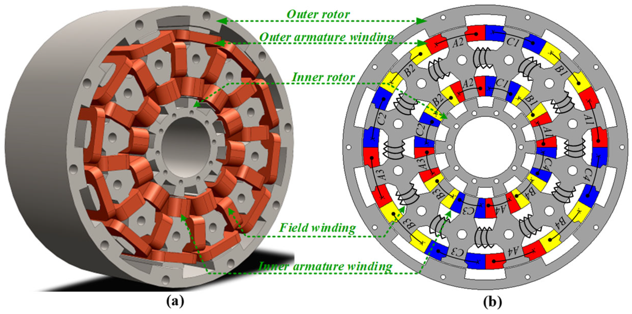
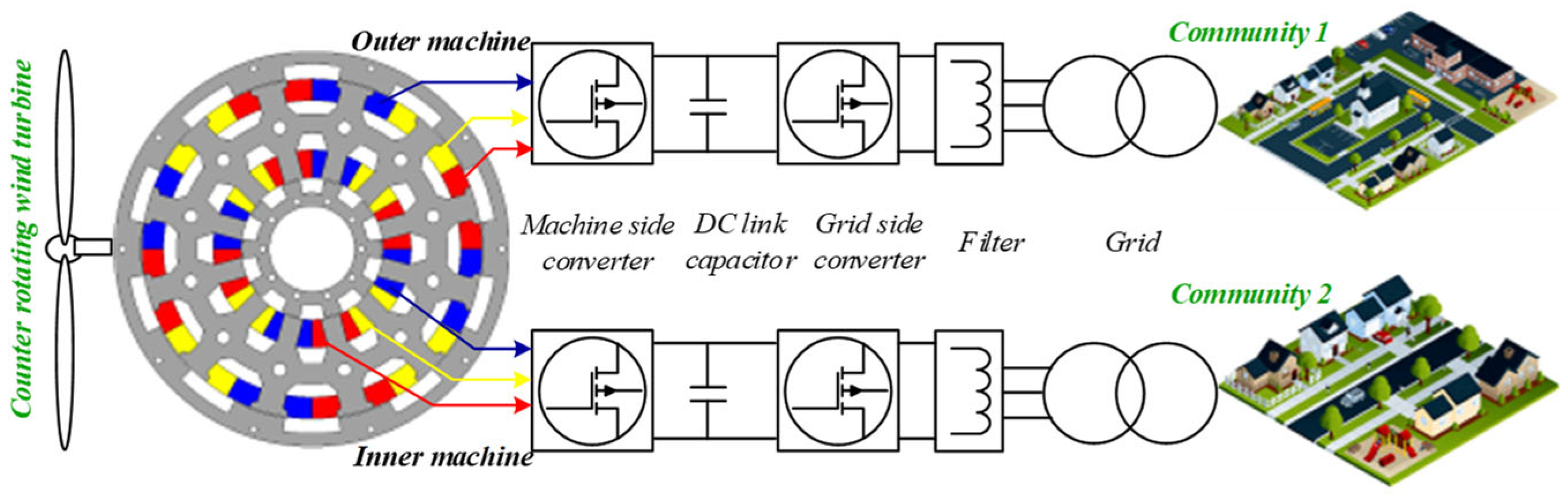
The design of the IDRWFFSG has two independent rotors in the inner and outer regions with 14 poles, allowing for better utilisation of the available space, with the key design parameters and specifications presented in [7,12]. The airgap length is 0.5 mm, while concentrated winding and toroidal winding configurations are used for the armature and field excitation, respectively, as shown in Figure 1. The independent dual armature concentrated winding is allocated on both boundaries of the shared stator with the common field excitation winding, as shown in Figure 1. Both the rotor (inner and outer) and the stator (with inner and outer armature) are independent of each other [12]. The inner rotor with the inner armature winding forms a sub-machine, i.e., the inner machine, whereas the outer rotor with the outer armature winding forms the outer machine. Thus, both sub-machines within the IDRWFFSG are integrated into the grid as shown in Figure 2, powering two different load points, each forming a unique electrical port, i.e., inner or outer ports.

Figure 1.
IDRWFFSG design with winding connection: (a) 3D view and (b) 2D cross-sectional view.
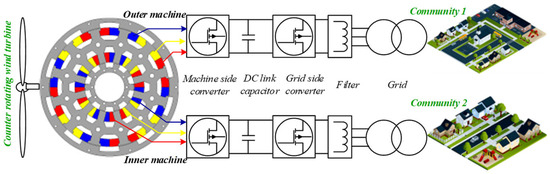
Figure 2.
Grid integration of the IDRWFEFSG with independent ports.
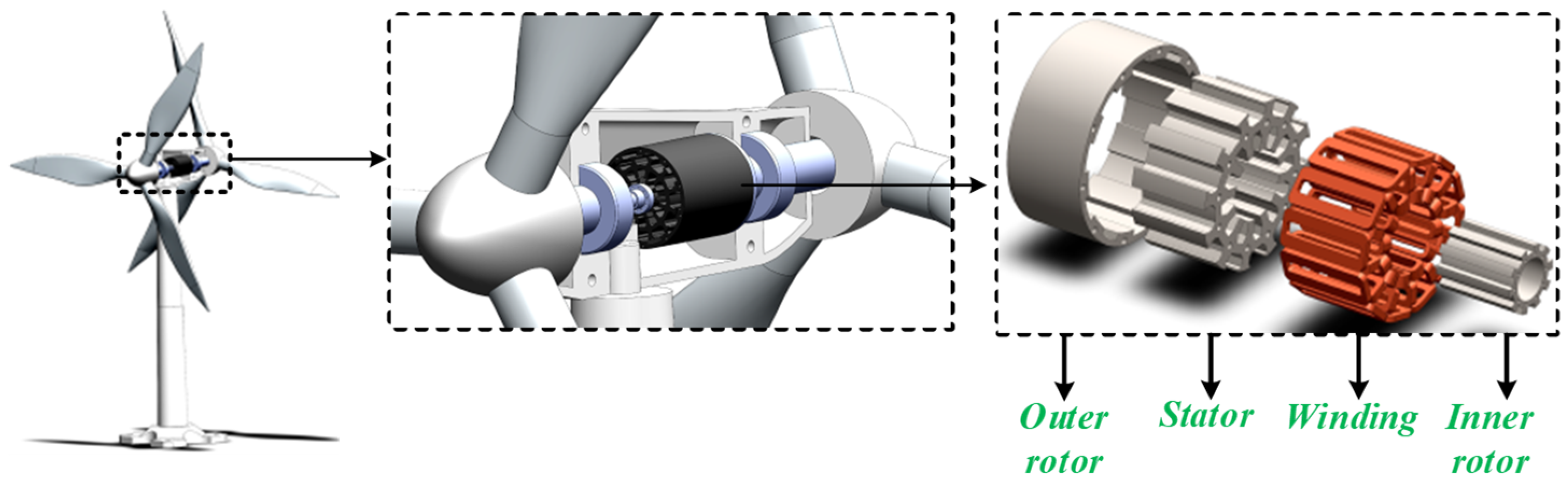
Since the proposed IDRWFFSG operates with independent rotors, an advanced dual wind blade counter-rotating wind turbine application is opted for as shown in Figure 3. The inner rotor is coupled to the inner blade, and the outer rotor is connected to the outer blade of the wind turbine system. Both inner and outer rotating-wind turbine blades are free and independent to rotate. Thus, under fault conditions in an off-grid system, a load point (community 1) can still be serviced even though the other load point (community 2) is disconnected. Therefore, the IDRWFFSG can serve two independent communities connected in an off-grid situation based on two independent port connections.

Figure 3.
Independent rotor connection of IDRWFEFSG-CRWT using dual wind blades.
This study investigates the effect of locked rotor fault withstand capability on the electromagnetic characteristics under four different locked rotor fault conditions as follows:
- (1)
- When the inner rotor is in a locked state and the outer rotor is operated in the clockwise direction—termed as C1.
- (2)
- When the inner rotor is in a locked state and the outer rotor is operated in the counterclockwise direction—termed as C2.
- (3)
- When the outer rotor is in a locked state and the inner rotor is operated in the clockwise direction—termed as C3.
- (4)
- When the outer rotor is in a locked state and the inner rotor is operated in the counterclockwise direction—termed as C4.
To protect the turbine from certain locked rotor fault conditions, wind turbine rotor blades are often constructed to be locked [13]. The above-mentioned locked rotor conditions are executed as indicated to secure the wind turbine system. There are several typical situations in which rotor blades might lock. Some of the common locked rotor conditions are explained as follows:
- A.
- High Wind Speeds: Rotor blades may be locked if wind velocity surpasses the turbine’s operating limits, which are normally between 55 and 70 miles per hour (25 and 30 m/s). Normally, the turbine control system initiates an automatic shutdown procedure in this locked circumstance, termed the overspeed protection mechanism, since it is above the cut-out speed. The rotor is often locked during this operation to reduce stress on the turbine parts such as the blades, rotor hub, and overall structure, as well as to guard against damage from exceptionally high wind speeds.
- B.
- Grid Fault or Power Loss: Wind turbines may have devices set up that remotely lock the rotor blades in the case of a grid fault or power outage. This is carried out to guarantee the security of maintenance workers who might be engaged in maintaining the grid or power lines.
- C.
- Emergency Shutdown: The rotor blades get locked in case of emergency shutdown to return the turbine to a safe state in specific emergency scenarios, such as mechanical failure or abnormal operating conditions.
- D.
- Abnormal Fault Condition: To continuously monitor their operation, modern wind turbines are fitted with a variety of sensors and control systems. The turbine may lock the rotor blades as a safety precaution if a fault or abnormal condition is identified to stop further damage or potential risks.
- E.
- Grid Stabilisation: Wind turbines may occasionally be able to help with grid stabilisation during power outages. To lower the output power and aid in frequency or voltage stabilisation of the electrical grid, this may include briefly locking the rotor blades.
- F.
- Lightning Protection: Wind turbines often have mechanisms functioning to lock the rotor blades as a preventative measure during thunderstorms or whenever there is a chance of lightning strikes. In addition to ensuring the safety of the turbine itself, this reduces the possibility of lightning harming the electrical components of the turbine.
It is worth noting that in each of the above faulty conditions for locked rotor, only one rotor locked condition is investigated, while the other is still in operating condition. Otherwise, when both rotors are locked, there is no power generation; therefore, this case has been ignored.
3. Formation of Magnetic Paths Under Normal and Locked Conditions
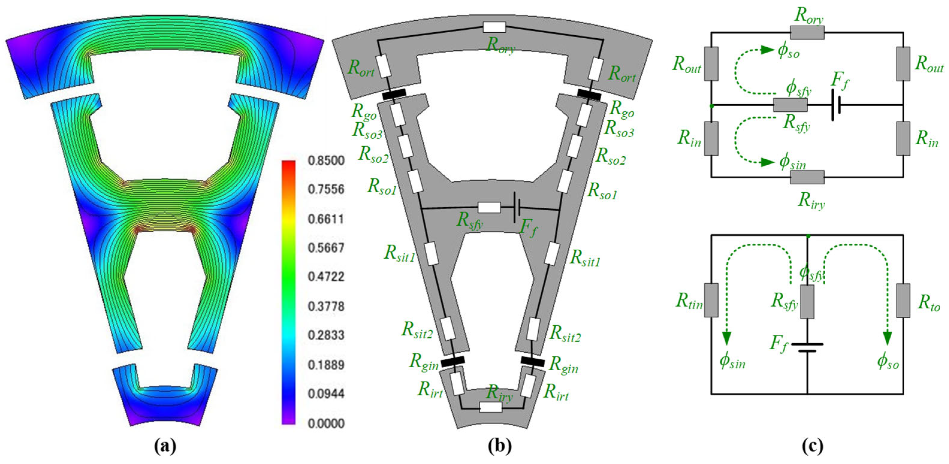
During normal operation, the magnetic flux path and circuit for one pole pitch of the IDRWFFSG are shown in Figure 4. It is evident that both the inner and outer sub-machines operate through parallel flux paths developed between the upper stator with the outer rotor, as well as the lower stator with the inner rotor. The magnetic paths are further simplified in the magnetic circuits shown in Figure 4c, illustrating the flux flow pattern. In [12], it can be inferred that the magnetic nodes in Figure 4c divide the flux between the upper and lower stator teeth. However, under a locked rotor fault scenario, the flux path varies significantly, resulting in variations in key electromagnetic performance. When one of the rotors is in a locked state, the magnetic path formed with respect to the other operating rotor changes to a series, parallel, or a combination of series and parallel magnetic paths as illustrated in Figure 5, ultimately affecting the electromagnetic characteristics.

Figure 4.
Magnetic flux and circuit under normal operation: (a) flux density distribution, (b) magnetic circuit, and (c) simplified magnetic circuit.
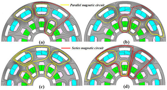
Figure 5.
Magnetic circuit under different faulty conditions: (a) C1, (b) C2, (c) C3, and (d) C4.
The magnetic path variation is investigated under four different locked rotor fault conditions. These locked rotor fault scenarios are considered based on the locking of the rotor and rotational direction of the independent rotors as shown in Figure 5, earlier categorised as C1, C2, C3, and C4 in Section 2.
4. Mathematical Modelling and Electromagnetic Characteristics
The dq mathematical modelling is linked with the FEM calculations, which considers the core material non-linearities to evaluate the electromagnetic performance characteristics of the machine under different locked rotor fault operating conditions. The IDRWFFSG comprises an armature and field winding in the stator, where the armature winding supplies power to the external load, and the field winding is supplied by an external DC source. Based on the presence of two windings, the mathematical model consists of armature and field parts. Since the mathematical model for each stator circuit is the same; therefore, only one stator circuit has been elucidated. In addition, the FEM-based mathematical modelling of different locked rotor positions is undertaken by setting the magnetic phase A of the armature currents to align with the rotor d-axis generated by the excitation current. An id = 0 control is implemented for maximum torque per ampere (MTPA) performance. Therefore, the voltage equations of each of these parts are written as follows [14]:
where and are field and armature voltages, respectively, and are field winding resistance and field current, respectively, and are the armature winding resistance and armature current, respectively, while and are the total flux linkages of the field and armature winding, respectively.
This total flux in the field and armature windings are expressed as
where is the mutual inductance between the armature and field winding, and and is the self-inductance of the armature and field windings.
Based on the flux linkage, the voltages of the field and armature windings are given as
Moreover, based on the co-energy method, electromagnetic torque () of the machine is expressed as
where the driving torque () from the wind turbine, according to system mechanical motion, is written as
where is the viscous coefficient, and is the rotor inertia.
It is noteworthy that the field winding provides flexibility in flux regulation of the machine, which can assist in regulation of the output power. Moreover, changing armature current also causes changes in the electromagnetic torque. Therefore, it is important to examine this torque profile under different locked rotor scenarios of zero driving torque of the wind turbine.
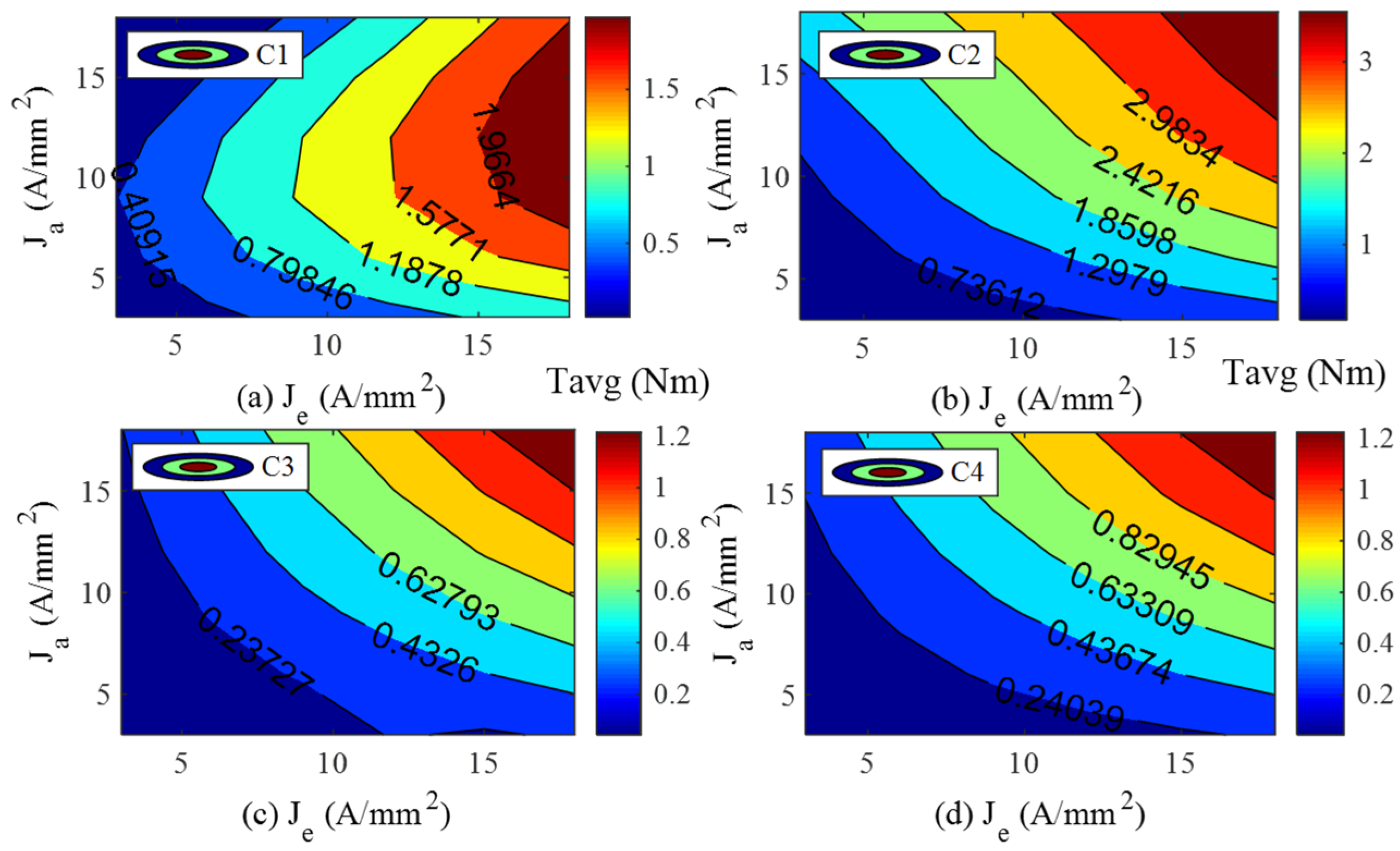
The electromagnetic torque of the four locked rotor fault scenarios, with varying armature current density () and field current density () are shown in Figure 6. The analysis shows that when the inner rotor is under locked condition and the outer rotor is operated clockwise (CW) in the case of C1, and counterclockwise (CCW) in the case of C2, the torque profile varies greatly in terms of the magnitude. Comparing C1 and C2, it is apparent that CW operation suffers from weak fault-tolerant capability, while CCW has better fault withstand capability. For CW operation in C1, the torque saturates faster and drops at higher current densities, whereas the torque increases with an increase in current density in the case of C2 for CCW operation, while retaining torque production capabilities under locked rotor fault withstand capability.

Figure 6.
Average torque () capability under (a) C1, (b) C2, (c) C3, and (d) C4.
Similarly, in the case of C3 and C4 conditions, when the outer rotor is subjected to a locked rotor fault, the torque profiles show an increasing trend with current, although the rate of increase varies. It is observed that the rate of increase is better in CCW than in the corresponding CW operation. This analysis reveals that under different rotor fault scenarios and rotor operating directions, the fault-tolerant capability is excellent in CCW than in CW operation.
Generally, in flux switching machines, the electromagnetic torque () comprises a DC component () and the amplitude of high-order harmonics torque (), as expressed below [15].
and
where is the harmonic phase angle, and is the fundamental frequency of the electromagnetic torque.
The higher-order harmonic components in the electromagnetic torque are due to the effect of cogging torque, which result in torque ripple. According to classical electrical machines theory, the torque ripple () is written as
and
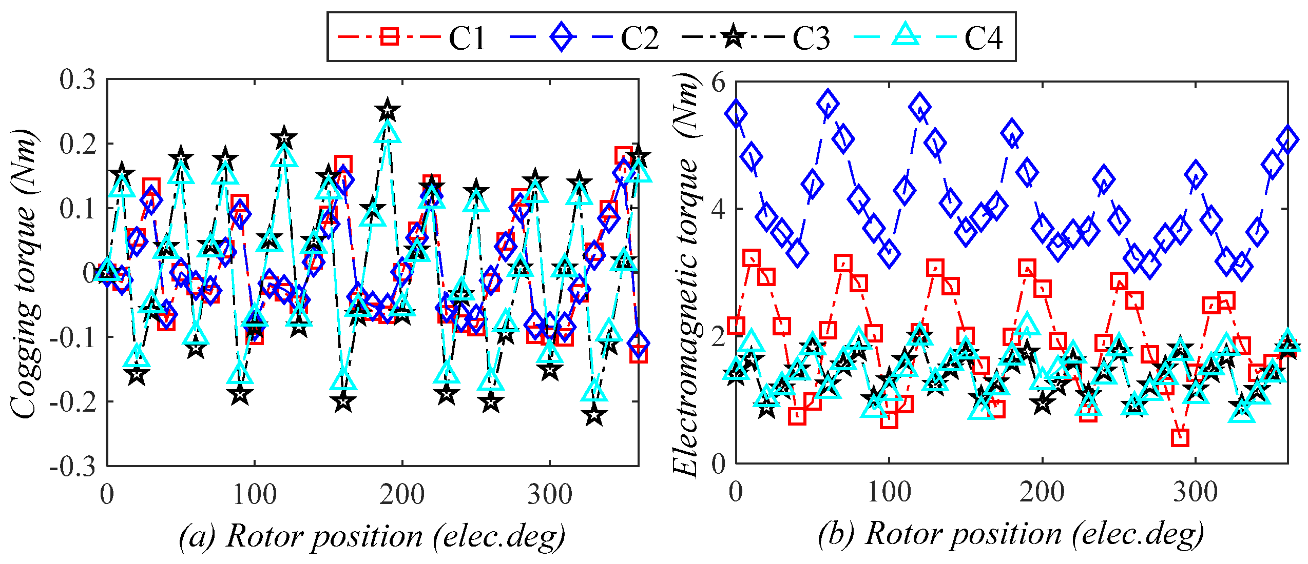
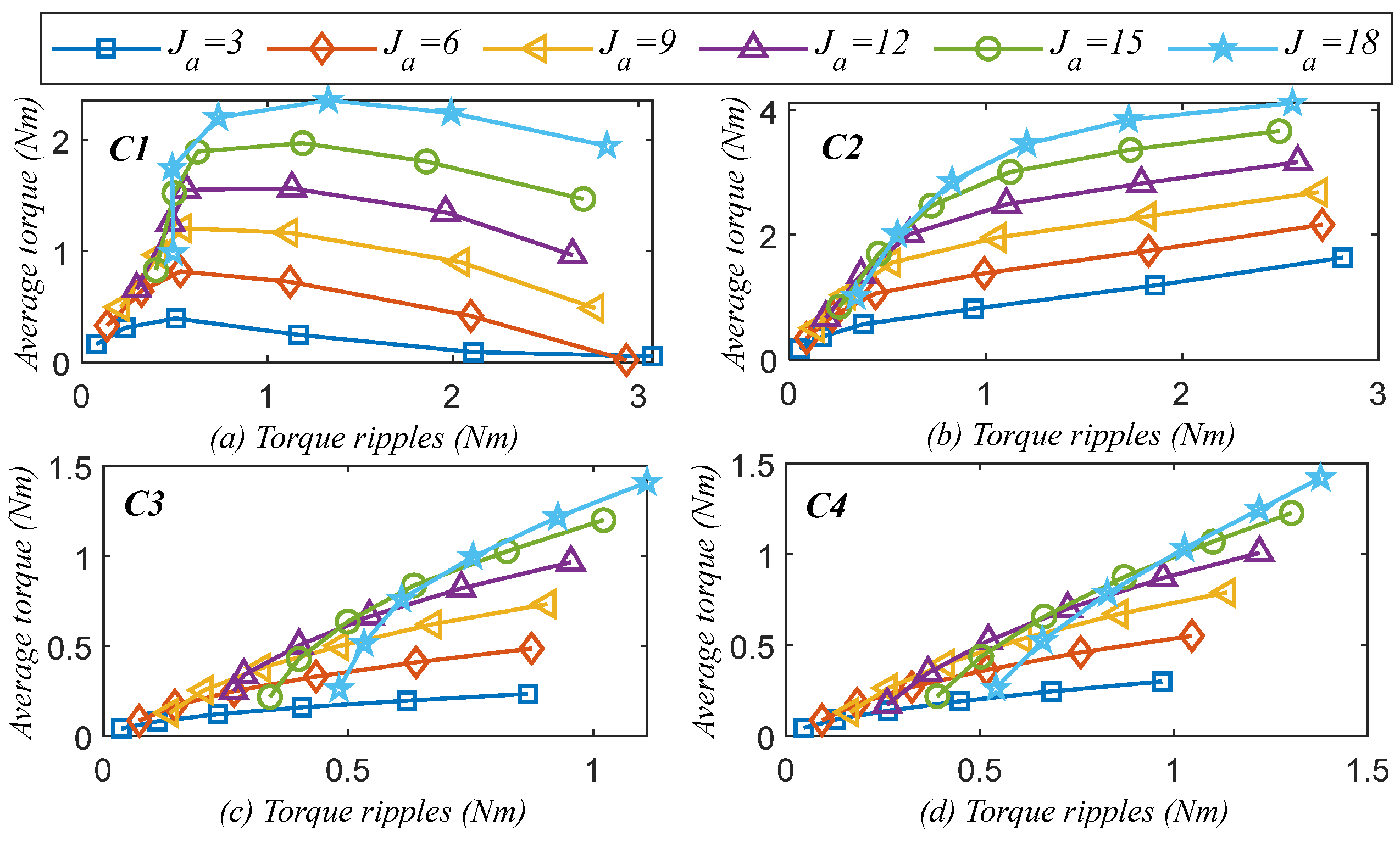
The cogging torque is shown in Figure 7a and is referred to the torque due to the presence of the excitation current only, caused by interaction between the no-load magnetic fields and slotting effects [16]. It is replicated in the instantaneous electromagnetic torque, as illustrated in Figure 7b in the form of pulsations, which result in torque ripple. The reluctance torque for these machine variants is negligible [17]. Since the cogging torque profiles change with the change in the locked rotor status and operating rotor’s direction, the resulting pulsations in the form of torque ripple vary in the electromagnetic torque. This variation in the torque ripple with the average torque and armature excitation current densities under the locked rotor conditions is examined in Figure 8. Note that, for the six legend markers in Figure 8, Figure 9, Figure 10, Figure 11 and Figure 12, the field excitation current density has been varied from 3 A/mm2 to 18 A/mm2.
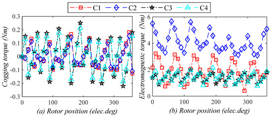
Figure 7.
Torque characteristics: (a) cogging torque and (b) electromagnetic torque.
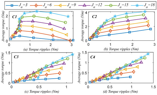
Figure 8.
Average torque versus torque ripple under (a) C1, (b) C2, (c) C3, and (d) C4.
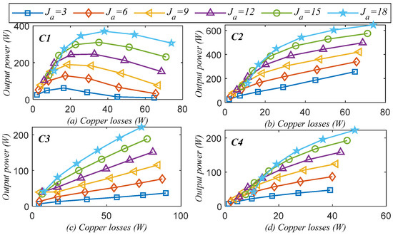
Figure 9.
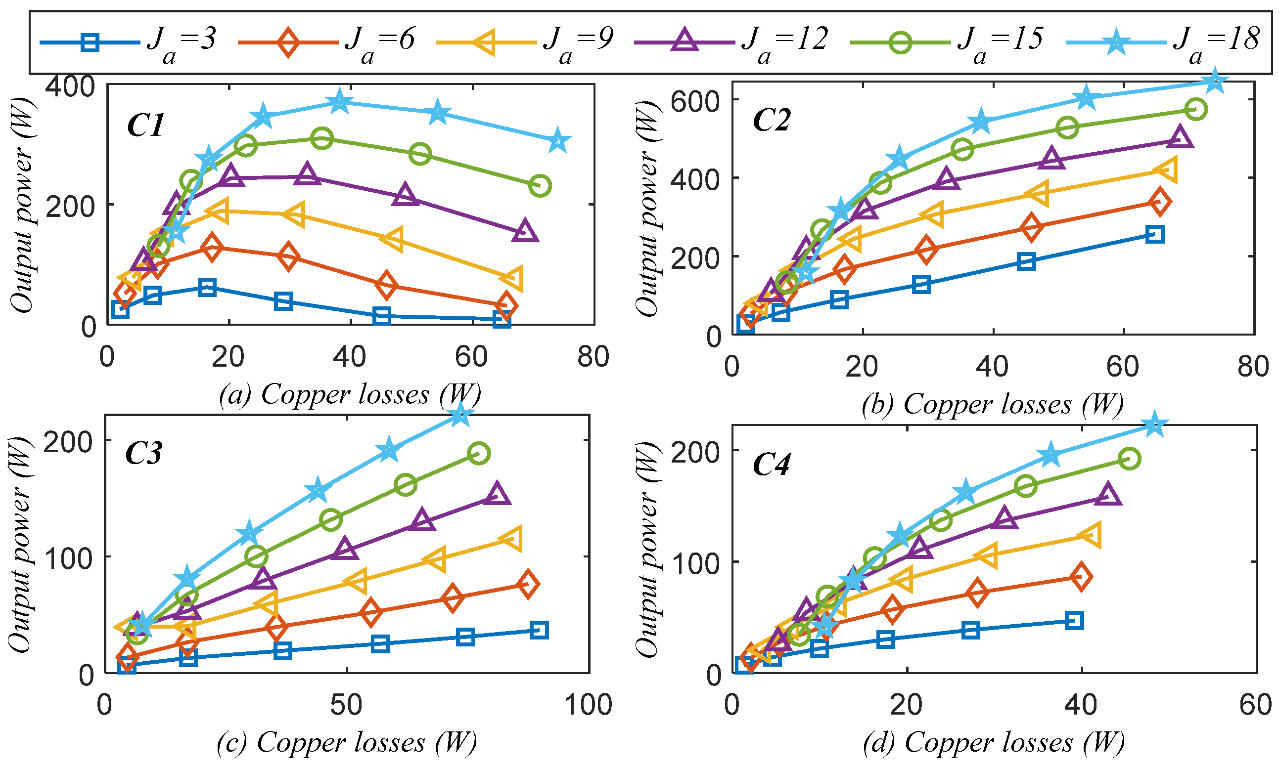
Output power versus copper losses under (a) C1, (b) C2, (c) C3, and (d) C4.
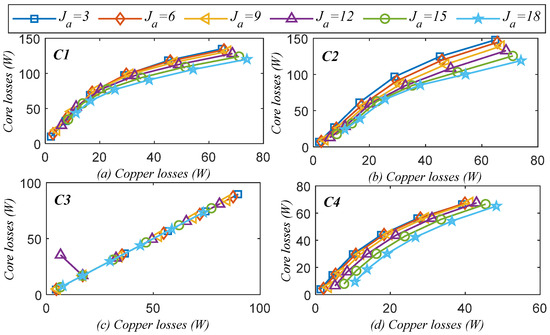
Figure 10.
Core losses versus copper losses under (a) C1, (b) C2, (c) C3, and (d) C4.
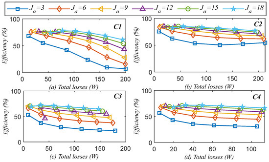
Figure 11.
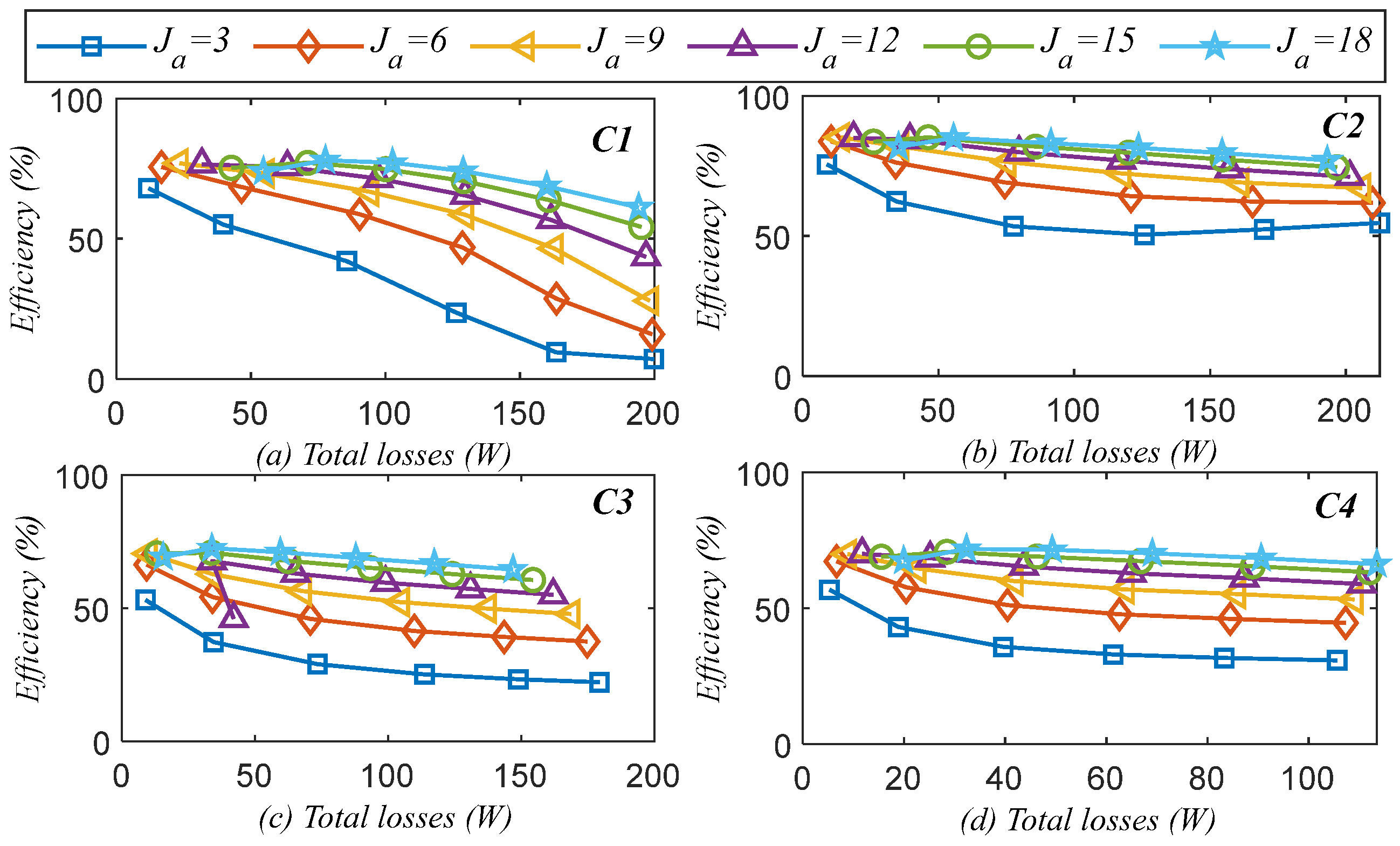
Variations in efficiency and total losses under (a) C1, (b) C2, (c) C3, and (d) C4.
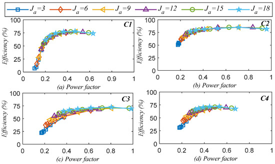
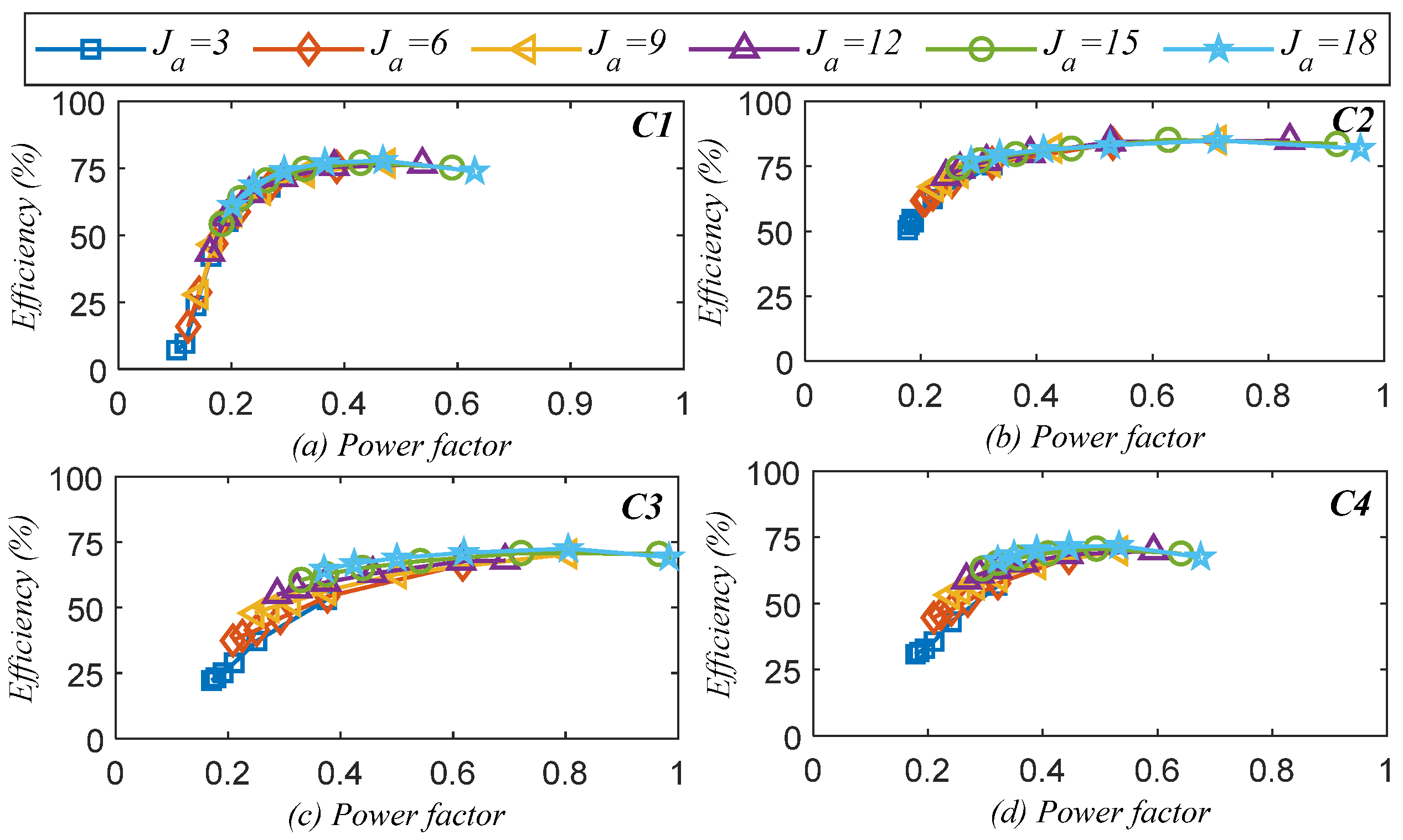
Figure 12.
Variations in efficiency and power factor under (a) C1, (b) C2, (c) C3, and (d) C4.
Cogging torque and torque ripple are a major challenge in wind generators, which proceed to vibrations and acoustics. The analysis in Figure 8 shows that for C1, when the inner rotor is locked and the outer rotor operates CW, the average torque increases with the increase in load but slightly drops under increased torque ripple. Comparing with C2, where the operation is in CCW, the average torque increases without negatively impacting the torque ripple. This shows that when the inner rotor is in a locked status, then operating the outer rotor in a CCW offers better fault-withstand capability for torque production. Similarly, for C3 and C4, when the outer rotor is locked and the inner rotor operates in CW and CCW, respectively, it is noticeable that there is no dominant effect over average torque due to increasing torque ripple. This analysis again shows the safe operation of the IDRWFFSG under various locked rotor conditions.
In the case of the generator operation, the electromagnetic power () also varies in accordance with the output torque as [18]
where is rated generator speed in r/min.
Keeping the speed constant, the output power changes with the changes in electromagnetic torque. The variation in the output power with the electromagnetic torque is at the same rate for all case studies, at which the average torque varies. However, losses also play a vital role in output power. Thus, the variation in the output power with the copper losses for all fault cases is shown in Figure 9. Based on the outcomes for different conditions in both CW and CCW, the analysis in the case of C1 for the outer rotor operating in the CW direction shows that the output power saturates and decreases with the increase in copper losses. Whereas in the case of C2 for CCW, the output power continuously increases. The decrease in the case of C1 is due to saturation effects. The analysis further reveals that under the same copper losses, the output power is improved for C2 when the outer rotor operates in the CCW direction. Moreover, in the case of C3 and C4, when the outer rotor is locked and the inner rotor is under normal operation, there are no dominant influences on the output power; however, copper losses increase more in C3 during CW operation than for C4 at CCW operation. This indicates that under all fault scenarios, output power is only dominantly affected in the case of C1, whereas for the remaining conditions, the locked rotor fault is withstood ensuring safe operation.
The energy efficiency of the IDRWFFSG is evaluated based on losses, efficiency, and power factor, by taking into account the presence of the field and armature windings. In spite of iron losses, the design is primarily affected by copper losses (field and armature copper losses). The effects of eddy current loss (), hysteresis loss (), and excess loss () on iron losses () are expressed as
where
Thus,
where , , and are material coefficients.
The total copper losses () are the sum of armature copper loss (), and the field winding copper loss () is expressed as follows [7]:
where
where is the armature winding resistance, is the slot area for the field winding, is the number of turns, is the machine stack length, and and are the d and q-axis currents, respectively.
The machine’s efficiency based on generator power flow is therefore given as follows:
Additionally, the power factor is computed based on the power triangle using the current control technique. In this method, the active power (), apparent power (), reactive power (), and power factor () are expressed as follows [19]:
Based on the above mathematical formulation, the IDRWFFSG is examined for losses, efficiency and power factor. The associated core and copper losses with the varying armature current density are displayed in Figure 10 for all four different fault scenarios. The analysis shows that, under the same copper losses, core losses in the cases of CW (C1 and C3) increase faster than for CCW (C2 and C4). Moreover, in the case of C3, when the outer rotor is locked and the inner rotor operates in the CW, the core losses increase linearly due to lower saturation effects, whereas for the remaining conditions, the core losses saturate at higher current densities.
So far, variations in the IDRWFFSG under different faults and operational directions are seen to impact machine losses and could ultimately affect the efficiency response. The effects of these variations in machine losses on efficiency across all different case studies are illustrated in Figure 11. Mathematical formulation and FEM reveal that under different fault conditions, variations in losses influence the minimum and maximum power. In the case of C1, where the outer rotor operates in the CW, the maximum and minimum efficiencies are 76.9% and 7.1%, respectively. The decrease in efficiency under locked rotor improves in the case of C2, which operates in the CCW. In this case, the maximum and minimum efficiency is computed at 85.1% and 54.7%, respectively. It is found that compared to C1 under CW, C2 under CCW shows better fault withstand capability and ensures reliable operation without negatively impacting the efficiency performance.
When the outer rotor is set under locked rotor and the inner rotor is operated in the CW, in the case of C3, the highest and lowest efficiencies are found to be 70.5% and 22.2%, respectively. Whereas in the case of C4, it is 69.9% and 30.8%, respectively. This analysis also validates that CCW offers a comparatively better response than CW. Moreover, it is noteworthy that in the case of CCW, not only is the maximum efficiency improved, but the maximum efficiency point is also improved. Thus, for the prerequisite demand of high efficiency under fault conditions, it is important to operate the healthy phase in CCW.
Finally, the efficiency of the IDRWFFSG is evaluated against the power factor for all conditions, as shown in Figure 12. It is noteworthy that efficiency reaches maximum values at certain values of power factor; however, the power can be improved at higher current density in tandem with the operational direction of the rotor. The analysis illustrates that in the case of C1, the maximum power factor reaches 0.63, but when the rotor is operated in CCW under the same faulty rotor, the power factor is improved to 0.95 due to an improvement in saturation level. However, this scenario reverses in the cases of C3 and C4. Thus, based on analysis, it is concluded that depending on the prerequisite demand of high efficiency, power factor, and output power for reliable and fault withstand capability, the rotational direction of the rotor can be altered when one of the rotors goes under a locked condition.
5. Impact of Locked Rotor Position on Non-Active Rotor
As earlier illustrated in Figure 5, the magnetic circuit formation depends on the relative positions of the inner and outer rotors, which results in changes in the magnetic circuit as well as electromagnetic performance. Therefore, to visualize the impact of the locked rotor position on the torque characteristics, this section is used to investigate the relative position of the locked rotor at various mechanical shifted () positions. To this end, the locked rotor position is investigated from with , while both the magnetic circuit and the torque profile are examined to show the impact on the torque profiles. To perform this analysis, the armature current is established as [20]
where is the peak armature current, is the current density, is the slot area, is the filling factor, and is the number of turns.
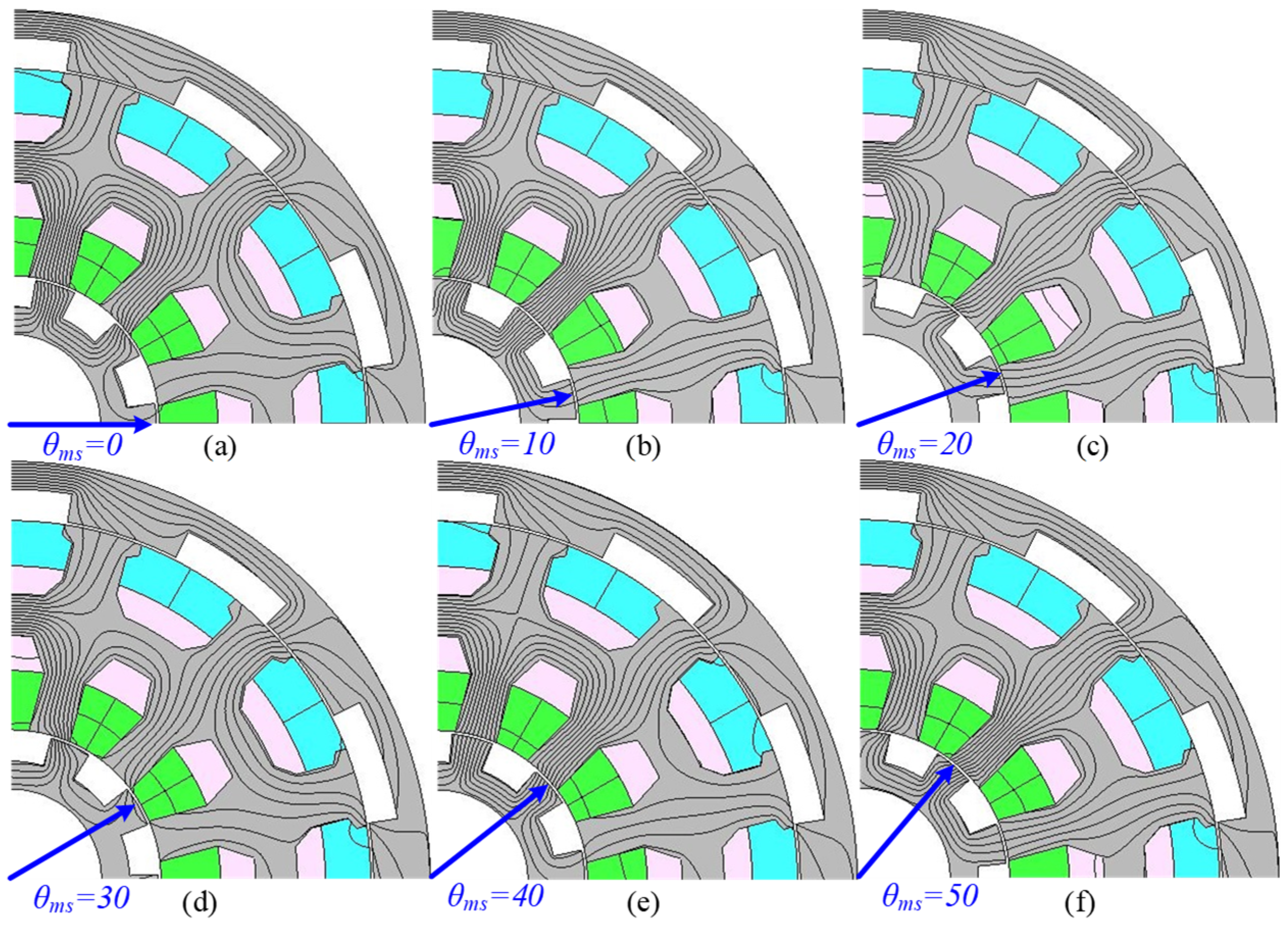
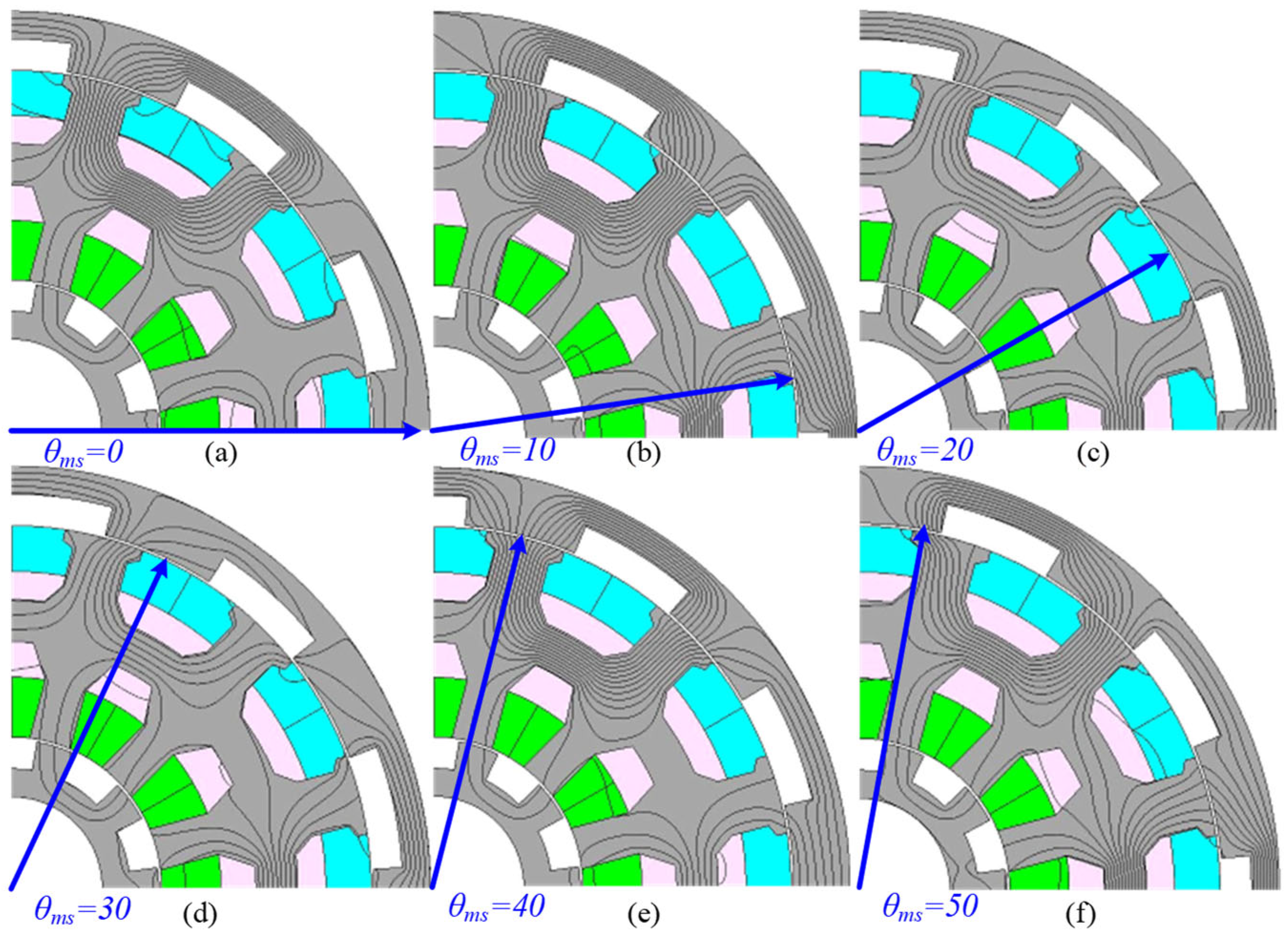
This variation in the magnetic circuit for C1 and C2 is illustrated in Figure 13, whereas for C3 and C4, the magnetic circuit formation is displayed in Figure 14. It can be clearly seen that with the , the magnetic circuit formation slightly varies and then repeats the previous state as the rotor moves from to for C1 and C2 and C3 and C4. These changes in the magnetic circuit cause variations in the torque profile in terms of the average torque and the torque ripple, as shown in Figure 15.
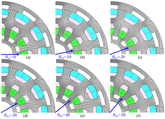
Figure 13.
Magnetic circuit formation with for C1 and C2, i.e., inner rotor locked position: (a) , (b) , (c) , (d) , (e) , and (f) .
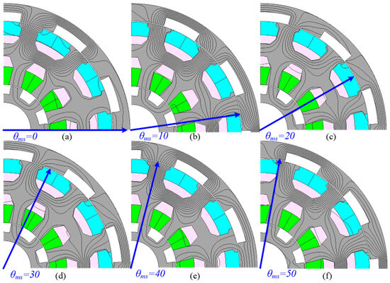
Figure 14.
Magnetic circuit formation with for C3 and C4, i.e., outer rotor locked position: (a) , (b) , (c) , (d) , (e) , and (f) .
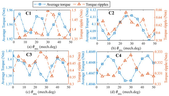
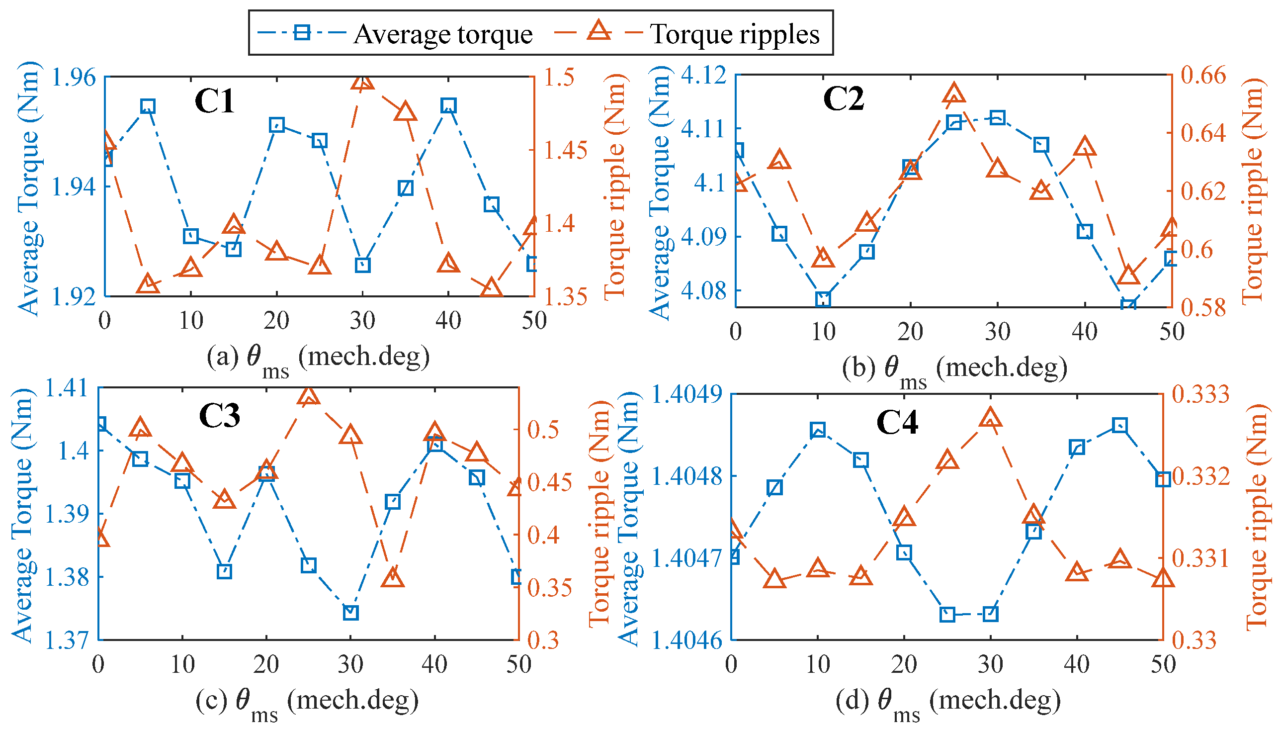
Figure 15.
Torque profile, i.e., average torque and torque ripples, with varying under (a) C1, (b) C2, (c) C3, and (d) C4.
Further analysis reveals that with the variation in , the torque profile greatly changes, as illustrated in Figure 15. It can be clearly seen for C1 in Figure 15a, at , the average torque increases whereas the torque ripple decreases. Whereas at , the average torque decreases, and the torque ripple increases. Similarly, for C2 in Figure 15b, it is evident that average torque and torque ripple either increase or decrease. For C3, in Figure 15c, it seems that the average torque decreases, whereas the torque ripple increases. Finally, for C4 in Figure 15d, it is apparent that the average torque increases with a decrease in torque ripple and vice versa. Thus, this analysis shows that for different locked rotor positions, there is an impact on torque profiles that ultimately affects performance. It is further important to note that the impact varies according to the rotational direction.
6. Experimental Validation
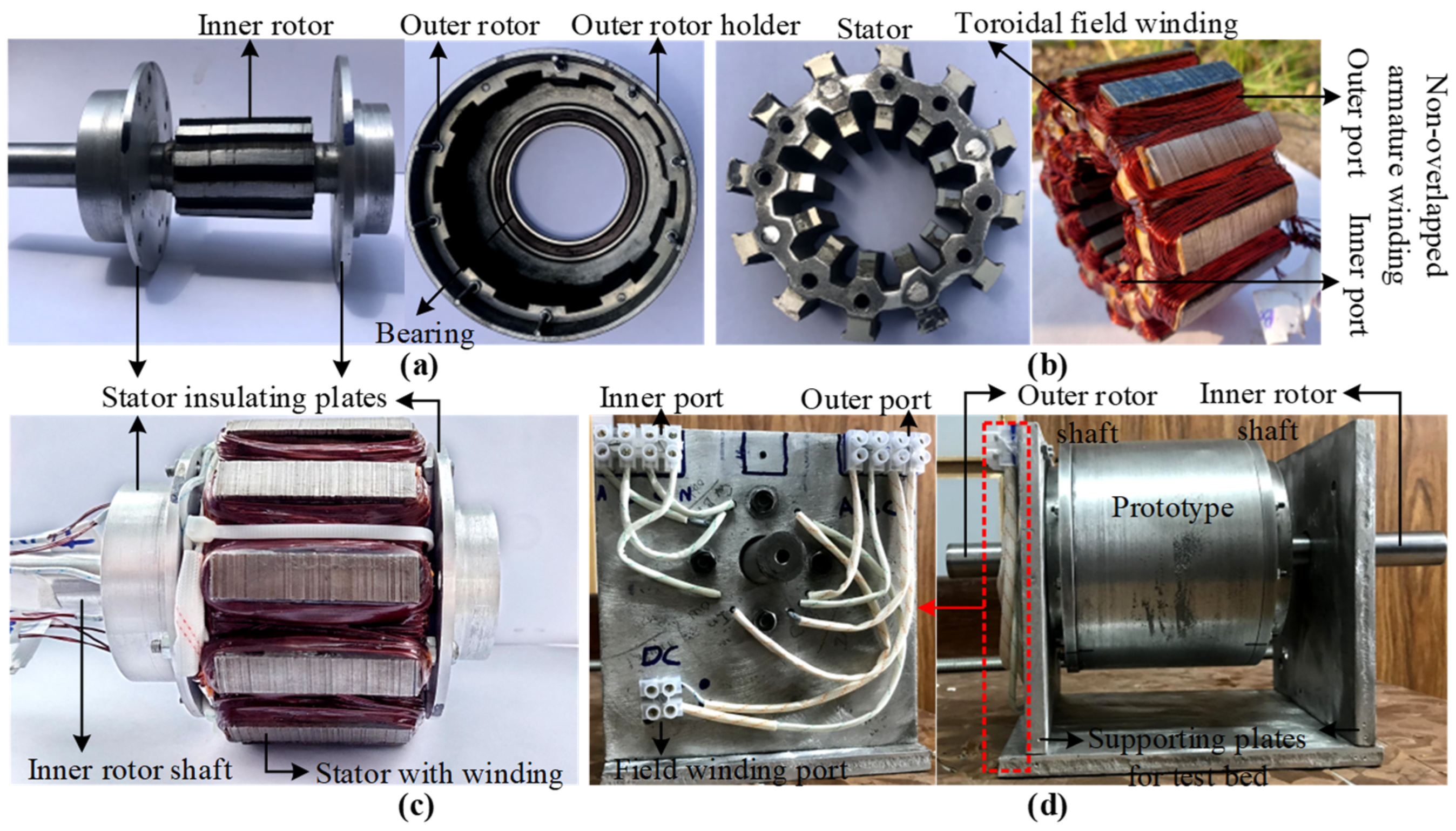
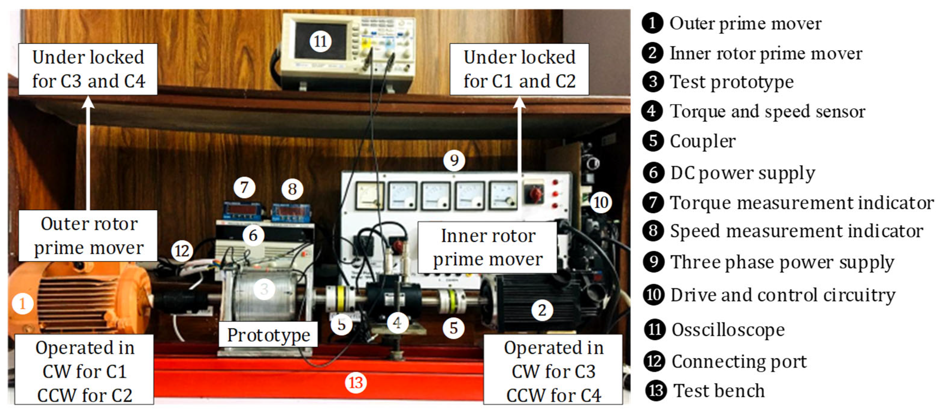
So far, the IDRWFFSG for CRWT application has been predicted using mathematical modelling and FEM analysis under different rotor locked conditions. A prototype of the IDRWFFSG-CRWT has been compared and validated based on a test prototype developed in [7]. Figure 16 shows the manufacturing process of the designed test prototype. Figure 16a shows both the inner and outer rotors, while the stator before and after inserting the windings is illustrated in Figure 16b. Moreover, the inner rotor is connected to the stator in Figure 16c, and the complete test prototype enclosure is assembled with the terminal connection displayed in Figure 16d. To test the prototype machine, the bench setup for experimental testing is shown in Figure 17. To test the IDRWFFSG under different locked rotor scenarios, two prime movers are connected to the independent rotors. In cases C1 and C2, the inner rotor prime mover was set under blocked conditions, while the outer rotor prime mover was operated in CW and CCW directions. Similarly, in cases C3 and C4, the outer rotor prime mover was set under blocked condition, while the inner rotor prime mover was operated in CW and CCW directions.
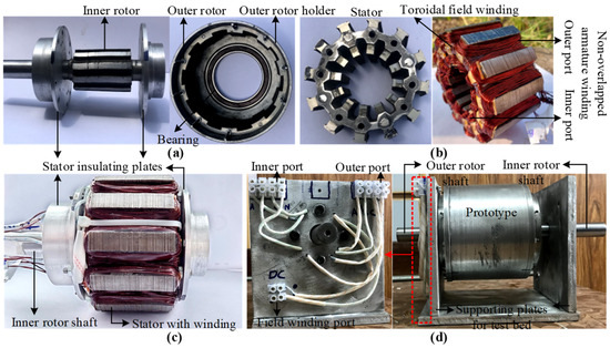
Figure 16.
Test prototype: (a) inner and outer rotor, (b) stator before and after winding, (c) inner rotor installation in stator, and (d) complete assembly and independent port connections.
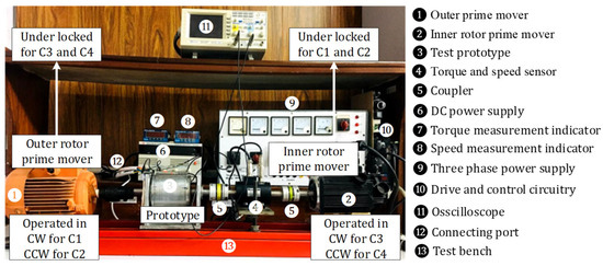
Figure 17.
Test bench setup of the IDRWFFSG for counter-rotating operation.
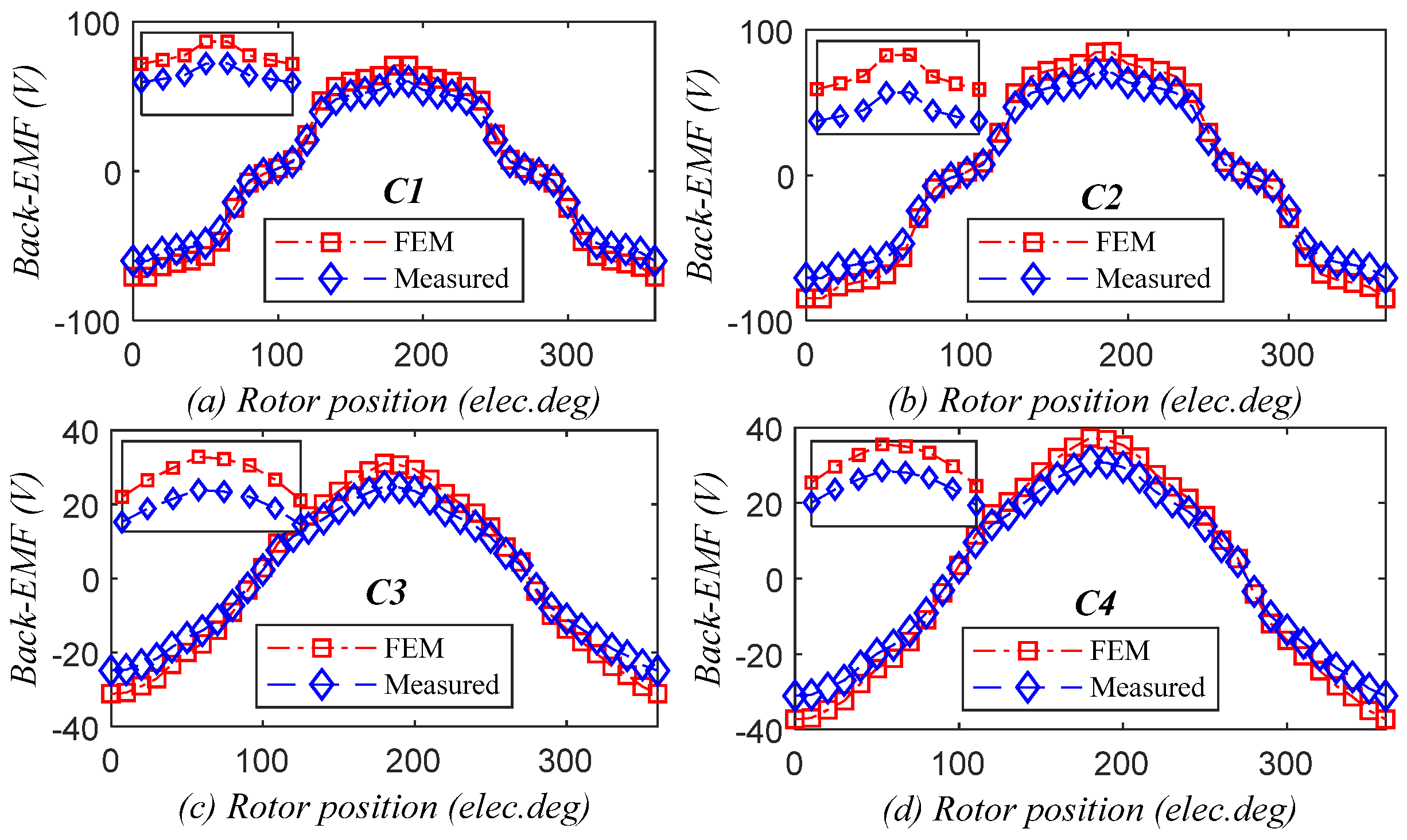
Experimental tests were conducted under both no-load and on-load states to confirm locked rotor fault withstand capability on the four scenarios of the IDRWFFSG prototype. Measurement test is conducted at different current densities for the on-load torque profile and under no-load for back-EMF measurements. Figure 18 shows the no-load back-EMF results for all four case studies. It is evident that both the FEM and experimental findings as compared were correctly matched.
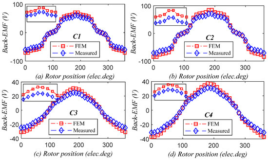
Figure 18.
No-load back-EMF @, 1500 r/min.
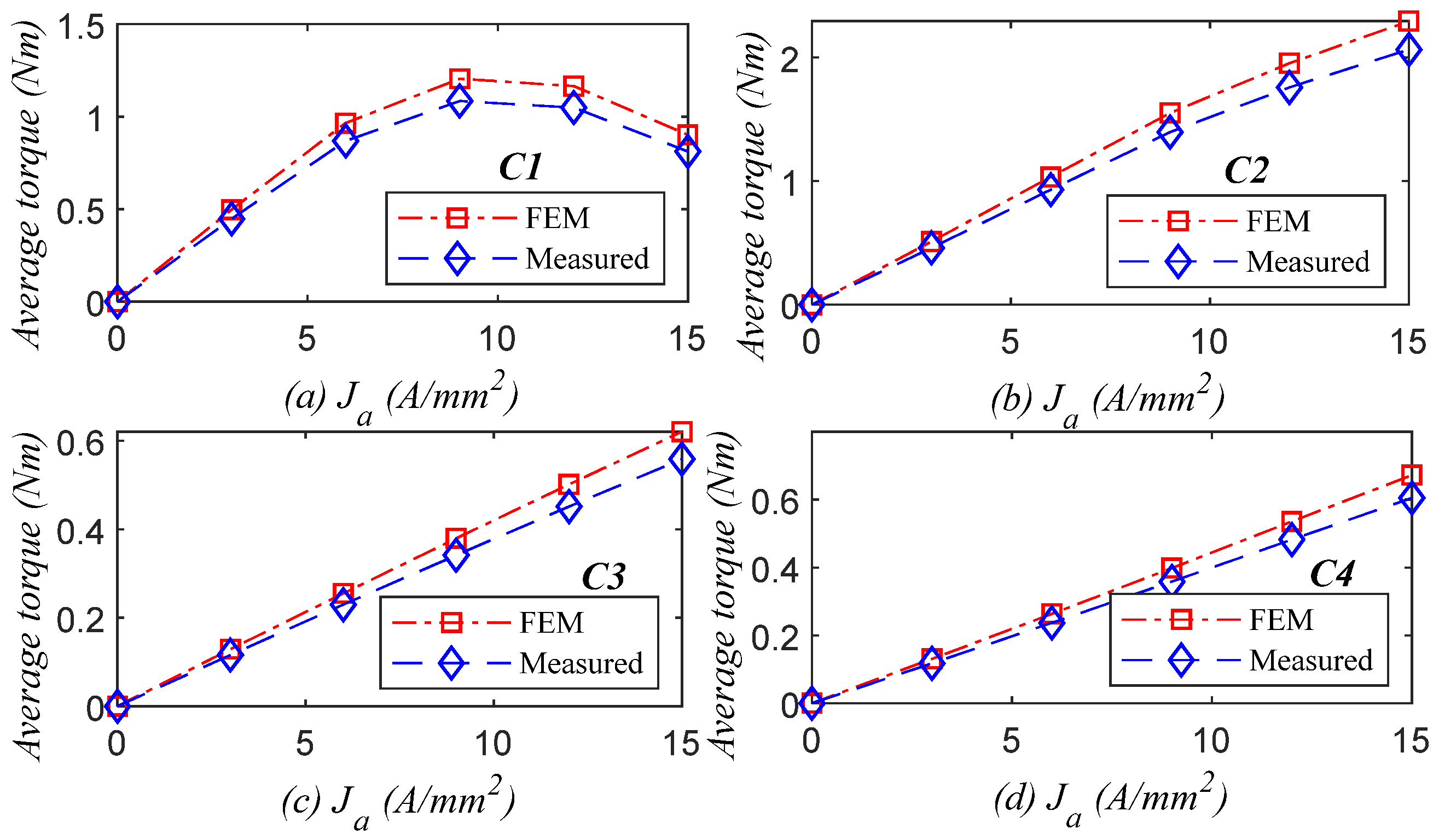
In addition, an on-load experimental test was conducted to determine the average torque profile at various current densities. Figure 19 displays the average torque profiles for the four different cases studied. The findings of the FEM and the experimental results were matched and found to support and verify the fault withstand capability study of the IDRWFFSG. Note that there are some little discrepancies between the FEM and experimental results caused by additional holes for nuts and bolts and manufacturing tolerance of the lamination core.
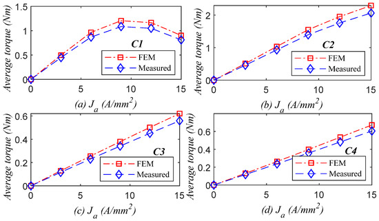
Figure 19.
On-load average torque @.
7. Conclusions
In conclusion, the IDRWFFSG for CRWT application has been analysed using mathematical modelling, FEM analysis, and experimental measurements to investigate the fault-tolerant capabilities under different locked rotor fault conditions. Four different fault scenarios, categorised as C1, C2, C3, and C4, based on the locking of the rotor as well as rotational direction (CW versus CCW) of the independent rotors, were considered. The main findings of this study are detailed as follows:
- Under different fault scenarios and rotor operation direction, CCW operation offers better fault withstand capability than CW operation.
- Cogging torque profiles change with changes in the locked rotor status and rotor operating direction, which results in torque ripples affecting the average torque across different fault scenarios.
- Variations in the output power with copper losses across all fault cases reveals that the output power is dominantly affected in the case of C1, whereas in the remaining cases, the locked rotor fault is withstood, ensuring safe operation.
- Variations in total machine losses on efficiency across all different cases showed that the maximum and minimum efficiency vary under different fault conditions, with CCW offering better response than CW.
- Experimental tests confirmed the fault withstand capability of the IDRWFFSG prototype, showing well-matched results when compared with FEM.
Overall, this study highlights the importance of considering locked rotor fault scenarios in the design and analysis of CRWTs and demonstrates the fault-tolerant capability of the IDRWFFSG under different fault conditions and rotor operation directions. It is particularly noted that depending on the prerequisite demand of high efficiency, power factor, and output power for reliable and fault withstand capability, the rotational direction of the rotor can be altered when one of the rotors goes under locked condition and that the magnetic circuit formation depends on relative positions of the inner and outer rotors, which impacts on the electromagnetic performance. The findings of this study can be useful to the development of more reliable and efficient CRWTs for renewable energy applications.
Future scope study will explore the fault-tolerant response of the IDRWFFSG under variable speed operation in fluctuating wind conditions, beyond the constant-speed cases evaluated in this study. Also, there is a need to evaluate different multiphase winding configurations and rotor pole combinations for robust fault-tolerant prediction of the IDRWFFSG electromagnetic performance in CRWT applications.
Author Contributions
Conceptualization, W.U. and F.K.; methodology, W.U.; software, W.U. and M.F.; validation, U.B.A., W.U. and F.K.; formal analysis, W.U., U.B.A. and M.F.; investigation, W.U., U.B.A. and M.F.; resources, F.K. and U.B.A.; data curation, W.U. and M.F.; writing—original draft preparation, W.U. and M.F.; writing—review and editing, U.B.A. and F.K.; visualization, W.U. and M.F.; supervision, F.K. and U.B.A. All authors have read and agreed to the published version of the manuscript.
Funding
This research received no external funding.
Data Availability Statement
The data that support the findings of this study are available on request from the corresponding author. The data are not publicly available due to privacy or ethical restrictions.
Conflicts of Interest
The authors declare no conflicts of interest.
References
- Gipe, P.; Möllerström, E. An overview of the history of wind turbine development: Part II–The 1970s onward. Wind Eng. 2023, 47, 220–248. [Google Scholar] [CrossRef]
- Cho, W.; Lee, K.; Choy, I.; Back, J. Development and experimental verification of counter-rotating dual rotor/dual generator wind turbine: Generating, yawing and furling. Renew. Energy 2017, 114, 644–654. [Google Scholar] [CrossRef]
- Newman, B.G. Actuator-disc theory for vertical-axis wind turbines. J. Wind. Eng. Ind. Aerodyn. 1983, 15, 347–355. [Google Scholar] [CrossRef]
- Wang, K.; Liu, T.; Wan, Y.; Ong, M.C.; Wu, T. Numerical Investigation on Aerodynamic Characteristics of Dual-Rotor Wind Turbines. J. Mar. Sci. Eng. 2022, 10, 1887. [Google Scholar] [CrossRef]
- Vasel-Be-Hagh, A.; Archer, C.L. Wind farms with counter-rotating wind turbines. Sustain. Energy Technol. Assess. 2017, 24, 19–30. [Google Scholar] [CrossRef]
- Oprina, G.; Chihaia, R.A.; El-Leathey, L.A.; Nicolaie, S.; Babutanu, C.A.; Voina, A. A Review on Counter-Rotating Wind Turbines Development. J. Sustain. Energy 2016, 7, 71–78. [Google Scholar]
- Ullah, W.; Khan, F.; Hussain, S.; Yousuf, M.; Akbar, S. A Novel Dual Port Dual Rotor Wound Field Flux Switching Generator with Uniform and Non-Uniform Rotor Poles for Counter-Rotating Wind Power Generation. IEEE Trans. Energy Convers. 2023, 38, 2420–2433. [Google Scholar] [CrossRef]
- Ullah, W.; Khan, F.; Akuru, U.B.; Hussain, S.; Yousaf, M.; Amuhaya, L.L. Design and Parametric Analysis of Dual Mechanical Port Field Excited Flux Switching Generator for Wind Turbine Applications. In Proceedings of the 2022 IEEE Energy Conversion Congress and Exposition (ECCE), Detroit, MI, USA, 9–13 October 2022; pp. 1–5. [Google Scholar] [CrossRef]
- Shen, W.Z.; Zakkam, V.A.K.; Sørensen, J.N.; Appa, K. Analysis of Counter-Rotating Wind Turbines. J. Phys. Conf. Ser. 2007, 75, 012003. [Google Scholar] [CrossRef]
- Saulescu, R.; Neagoe, M.; Jaliu, C.; Munteanu, O.A. Comparative Performance Analysis of Counter-Rotating Dual-Rotor Wind Turbines with Speed-Adding Increasers. Energies 2021, 14, 2594. [Google Scholar] [CrossRef]
- Selema, A. Development of a Three-Phase Dual-Rotor Magnetless Flux Switching Generator for Low Power Wind Turbines. IEEE Trans. Energy Convers. 2020, 35, 828–836. [Google Scholar] [CrossRef]
- Ullah, W.; Khan, F.; Akuru, U.B.; Hussain, S.; Yousuf, M.; Akbar, S. A Novel Dual Electrical and Dual Mechanical Wound Field Flux Switching Generator for Co-Rotating and Counter-Rotating Wind Turbine Applications. IEEE Trans. Ind. Appl. 2024, 60, 184–195. [Google Scholar] [CrossRef]
- Kang, J.H.; Lee, H.W. The development of rotor brakes for wind turbines. In. J. Appl. Eng. Res. 2017, 12, 5094–5100. [Google Scholar]
- Yu, C.; Niu, S. Development of a Magnetless Flux Switching Machine for Rooftop Wind Power Generation. IEEE Trans. Energy Convers. 2015, 30, 1703–1711. [Google Scholar] [CrossRef]
- Jiang, M.; Zhu, X.; Xiang, Z.; Quan, L.; Que, H.; Yu, B. Suppression of Torque Ripple of a Flux-Switching Permanent Magnet Motor in Perspective of Flux-Modulation Principle. IEEE Trans. Transp. Electrif. 2022, 8, 1116–1127. [Google Scholar] [CrossRef]
- Zhang, W.; Wu, Z.; Hua, W.; Zhu, Z.Q. Reduction of Open-Circuit DC Winding Induced Voltage and Torque Pulsation in the Wound Field Switched Flux Machine by Stator Axial Pairing of Tooth Tips. IEEE Trans. Ind. Appl. 2022, 58, 1976–1990. [Google Scholar] [CrossRef]
- Zhu, Z.Q.; Wu, Z.Z.; Evans, D.J.; Chu, W.Q. A wound field switched flux machine with field and armature windings separately wound in double stators. IEEE Trans. Energy Convers. 2015, 30, 772–783. [Google Scholar] [CrossRef]
- Potgieter, J.H.J.; Kamper, M.J. Design Optimization of Directly Grid-Connected PM Machines for Wind Energy Applications. IEEE Trans. Ind. Appl. 2015, 51, 2949–2958. [Google Scholar] [CrossRef]
- Akuru, U.B.; Kamper, M.J. Presentation of novel high torque density dual-stator wound-field flux modulation machines. In Proceedings of the 2020 IEEE International Conference on Electrical Machines (ICEM), Gothenburg, Sweden, 23–26 August 2020; Volume 1. [Google Scholar]
- Sun, Y.; Wang, P.; Nie, R.; Nie, F.; Gao, P.; Si, J. Comparative Study of High-Speed Permanent Magnet Synchronous Motors with In-line Slot Conductors and Equidirectional Toroidal Windings. ACES J. 2024, 39, 555–564. [Google Scholar] [CrossRef]


Disclaimer/Publisher’s Note: The statements, opinions and data contained in all publications are solely those of the individual author(s) and contributor(s) and not of MDPI and/or the editor(s). MDPI and/or the editor(s) disclaim responsibility for any injury to people or property resulting from any ideas, methods, instructions or products referred to in the content. |
© 2025 by the authors. Licensee MDPI, Basel, Switzerland. This article is an open access article distributed under the terms and conditions of the Creative Commons Attribution (CC BY) license (https://creativecommons.org/licenses/by/4.0/).