Abstract
The involute gear with variable tooth thickness lacks established methods for calculating meshing heat and studying oil-jet lubrication and cooling effects. This study aims to theoretically estimate the meshing heat generated during the engagement process of involute gears with variable tooth thickness. To achieve this, a heat calculation model is derived based on the corresponding tooth surface equations. The impact of oil-jet lubrication parameters—jet velocity, pitch cone angle, face width ratio, and axial displacement—on the gear surface temperature and internal gearbox environment is systematically studied. Numerical simulations of the temperature field are validated through experimental measurements. The results indicate that an oil-jet velocity of 15 m/s combined with a pitch cone angle of 4° significantly reduces both gear surface and internal flow field temperatures. Additionally, smaller face width ratios and axial displacements effectively lower the internal temperature of the gearbox. These findings offer a theoretical basis for calculating meshing heat and designing oil-jet lubrication systems for variable-tooth-thickness involute gears.
1. Introduction
The thermal performance management of gear transmission systems has long been a critical issue in engineering applications [1]. The primary objective is to effectively reduce the frictional heat generated in the gear meshing region [2,3,4] thereby improving operational efficiency and extending gear service life. In addition, it is essential to mitigate wear and thermal scuffing caused by temperature fluctuations [5,6,7,8] ensuring the stability and reliability of the transmission system. This research topic holds significant importance for enhancing the transmission efficiency of mechanical systems and promoting energy conservation and emission reduction.
Early studies investigated thermal behavior using disc and single-gear experiments, leading to numerous empirical formulas [9,10,11,12,13,14]. In recent years, an increasing number of scholars have adopted numerical methods to compensate for the limitations of experimental approaches. Andersson et al. [15] found that spray lubrication enhanced efficiency, while immersion lubrication led to lower gear temperatures in FZG tests. Ambrose et al. [16] showed that XFlow’s results matched those of SPH, and LBM offered greater computational efficiency. Furthermore, Keller et al. [17] found that the single-phase SPH method was more time efficient, and that increasing the spray angle reduced the diffusion effect.
Gradually, researchers have shifted their focus to the influence of jet system layout parameters and configurations on gear lubrication behavior. Akin and Townsend [18,19,20,21] were among the first to establish an analytical model for gear oil-jet impingement depth. They investigated the matching relationship between the oil jet velocity and the gear line speed, laying the groundwork for subsequent studies on gear jet lubrication. Li et al. [22] developed a numerical model and found that increasing the oil film thickness and length could reduce frictional power losses and improve transmission efficiency. Dai et al. [23,24] examined the effect of various nozzle deflection angles on lubrication performance. Their results indicated that deflecting the nozzle toward the driving gear enhances the oil volume fraction within the meshing region. A mathematical model of jet impingement depth was also developed, demonstrating a positive correlation with the oil volume fraction and pressure in the meshing zone [25,26]. Liu et al. [27] developed a single-stage gear oil-jet model, analyzing how jet flow rate, speed, and viscosity affect lubrication, and proposed a CFD modeling approach. Interestingly, research strategies surrounding churning lubrication have also garnered significant attention. Liu et al. [28] investigated oil distribution and churning losses in a single-stage gearbox, with the results aligning closely with experimental data. Another approach employed particle-based flow simulation software to analyze the gear churning process [29].
In addition, gear surface temperature variation serves as a key indicator for evaluating lubrication and heat dissipation performance. Consequently, many researchers have focused on the temperature distribution of gears. Wang et al. [30] extracted convective heat transfer coefficients and performed thermal field simulations, analyzing the influence of jetting parameters on heat transfer. The results indicated that reducing nozzle diameter, increasing nozzle count, and raising oil supply pressure enhance cooling performance. Luo et al. [31] investigated the effect of gear profile modifications on temperature rise, identifying meshing stiffness, equivalent curvature radius, and load distribution as dominant factors. Fatourehchi et al. [32] combined tribological and thermal flow coupling analyses to predict heat generation and dissipation in re-lubricated gearboxes. Deshpande et al. [33] developed a thermo-fluid–solid model, showing lower temperatures on the disengagement side under varying nozzle layouts. Qiao et al. [34] computed the gear surface temperature field by solving for dynamic load and vibration displacement, and subsequently calculating the frictional heat flux.
While conventional gear cooling has been extensively studied, research on oil-jet cooling for variable-tooth-thickness gears remains scarce. Though gearbox thermal fields have been studied, meshing temperatures under varying speeds, pitch angles, face-width ratios, and axial offset remain underexplored. Moreover, the optimization of surface temperature in variable-tooth-thickness gears warrants further investigation. This study introduces a multi-factor framework to assess how pitch angle, jet velocity, face-width ratio, and axial offset collectively affect thermal behavior in variable-tooth-thickness gears. Numerical simulations and experiments jointly evaluate thermal response under coupled conditions, offering insights for advanced gear thermal management.
2. Mathematical Models and Methods
2.1. Mathematical Equations of Involute Variable-Tooth-Thickness Gears
The variable tooth thickness gear was designed based on the instantaneous axial surface. Since the gear defined on the pitch surface cannot satisfy the required center distance between the driving and driven gears, a pitch cone must be adopted for design purposes [35,36,37]. As shown in Figure 1, point M lies on the working pitch cone, with representing the working pitch cone angle and n denoting the unit normal vector. In Figure 2, denotes the fixed coordinate system, while and represent the coordinate systems of the driving and driven gears, respectively. Although theoretically line contact occurs between the variable tooth thickness gear and the rack cutter, actual transmission involves point contact at point P. Point denotes the shortest distance between the pitch cones, and is the shortest distance from the cone apex along its axis. Vectors , , , , , and represent the unit direction vectors along the generatrix of the pitch cones for gears 1 and 2, the working pitch cone angles, and the working pitch radii, respectively. The pitch cone equation in coordinate system is expressed as:
where point M has coordinates ; denotes the distance from point M along the pitch cone generatrix to the cone apex; and represents the developed angle of point M in the plane. Then, the unit normal vector on the pitch cone generatrix can be expressed as:
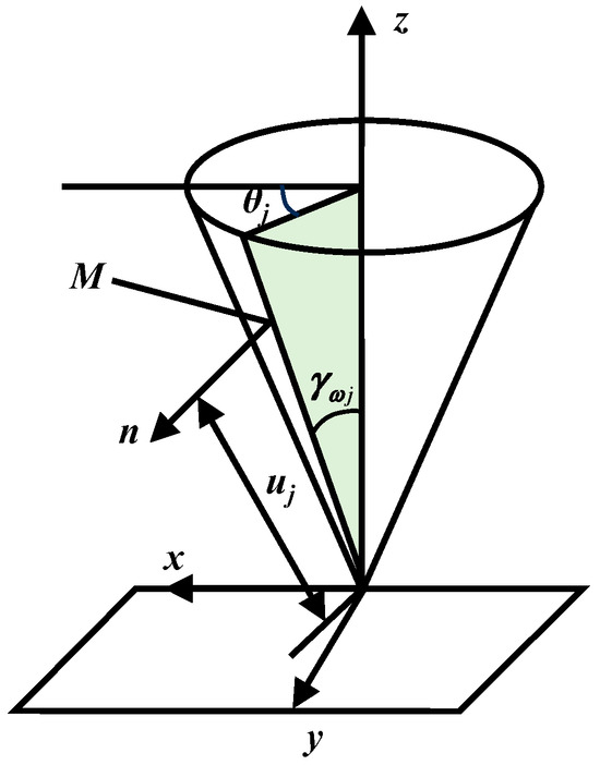
Figure 1.
Working pitch cone.

Figure 2.
Model of the working pitch cone with variable tooth thickness for parallel axes.
The equation of the contact point is derived through the transformation relationship between coordinate systems.
In the equation, denotes the position vector of the contact point P on gear j; represents the unit normal vector at the contact point P on gear j.
Given that , it follows that:
Furthermore, since , the relationship between the two pitch cone angles can be expressed as:
By simplification, the mathematical expressions of and can be obtained as follows:
2.2. Gear Solid Modeling
Due to the non-uniform profile shift along axial sections, a tooth surface-based mathematical model is required instead of standard 3D software features. Based on the pitch cone mathematical model presented in Section 2.1, an accurate tooth surface equation can be derived, enabling the construction of a digital 3D model. Figure 3 shows the MATLAB 2018b-generated tooth surface point cloud of a parallel-axis variable tooth thickness spur gear that was used to construct the 3D solid model.
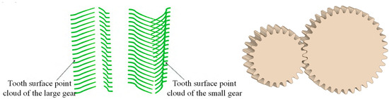
Figure 3.
Gear point cloud and geometric model.
Due to the involvement of oil spraying in actual operating conditions, a closed gearbox model is further created based on the generated gear model (see Figure 4). The minimum clearance between the gear tooth tip and the gearbox wall is 10 mm, while the distance between the gear end face and the gearbox wall is 8 mm. Additionally, an oil injection inlet is placed at the top of the gearbox, and an oil outlet is provided on the side. The oil spraying flow rate is set between 0.4 and 0.75 L/min, with the injection nozzle diameter of 1.3 mm and the oil outlet diameter of 10 mm. Basic parameters of the involute gear with variable tooth thickness are shown in Table 1.

Figure 4.
Gearbox model.

Table 1.
Basic parameters of the involute gear with variable tooth thickness.
2.3. Fluid Governing Equations
The jet lubrication process for involute gears with variable tooth thickness constitutes a two-phase flow problem. To establish a gear heat dissipation model within computational fluid dynamics (CFD), the Volume of Fluid (VOF) model is employed. It is assumed that the oil and air phases are homogeneously mixed. In terms of heat transfer, both convective heat exchange and thermal conduction effects are considered. The effects of thermal radiation from the gear, as well as thermal variations induced by changes in fluid kinetic energy, are neglected. The governing equations for fluid flow [35] are as follows:
Continuity equation:
where ρ denotes the phase density and v represents the phase velocity.
Momentum equation:
where P denotes the static pressure, gi and Fi represent the gravitational force and external body forces, respectively, and τij denotes the stress tensor.
Energy equation:
where cp is the specific heat capacity, T is the fluid temperature, k is the thermal conductivity, and ST is the viscous dissipation term.
Additionally, the fluid must satisfy the volume fraction continuity equation, which is expressed as Equation (11) as follows:
where N is the number of phases; for this two-phase flow model, N is taken as 2. ra denotes the volume fraction of fluid phase , which in this case refers to the mixture of lubricating oil and air. To enhance the efficiency of numerical analysis of turbulence within the gearbox, the Renormalization Group (RNG) model is employed. The RNG k-epsilon model accounts for the stochastic effects of turbulence through time-averaged treatment and is well-suited for simulating flows with high curvature and strong pressure gradients. The governing equations of the RNG k-epsilon model are expressed as follows:
where k represents the turbulent kinetic energy, and is the turbulent dissipation rate. Gk denotes the generation of turbulent kinetic energy due to the mean velocity gradient, while Gb accounts for the generation of turbulent kinetic energy due to buoyancy. Ym represents the fluctuation-induced expansion in compressible fluids. Constants , and are model-specific coefficients, and and are the turbulent Prandtl numbers for k and , respectively. The effective viscosity is given by , where is the dynamic viscosity of the fluid and is the turbulent viscosity. Finally, and are the source terms for the turbulent kinetic energy and dissipation rate, respectively.
To analyze the gearbox’s transient flow field, the VOF two-phase model is employed for its accuracy in capturing oil–air distribution and lubrication patterns in critical regions. The volume equation for the p-phase fluid across the tracked phase interface is given by:
where denotes the volume fraction of the p-phase fluid; ui is the velocity component; t represents time; and xi is the spatial coordinate component.
Additionally, when the fluid flows over the gear surface, heat transfer occurs, which can be addressed using Newton’s law of cooling.
where q denotes the heat flux density (W·m−2), h is the convective heat transfer coefficient (W·m−2·K−1), tw is the temperature of the solid wall surface (K), and tf is the characteristic temperature of the fluid (K). For internal flow, tf is the cross-sectional average fluid temperature; for external flow, it is the fluid temperature away from the wall.
2.4. Heat Generation in Gear Meshing
The axial sliding in meshing allows the variable tooth thickness gear to be approximated as a helical gear in terms of load and friction behavior. Therefore, the equivalent helical gear model can be used to approximate the analysis of sliding frictional heat generation. The sliding frictional heat flux can be determined by calculating the work carried out by the friction force during meshing. In this formulation, Fn is the normal load on the tooth surface (N), f is the coefficient of sliding friction [36], and vt is the relative sliding velocity at the tooth surface (m/s).
Further, a force analysis of the involute variable tooth thickness gear under steady-state conditions is conducted, as shown in Figure 5. Fax, Fmt and Frd represent the axial force, the tangential force, and the radial force, respectively. If the torque is denoted as T and dm is the pitch diameter at the middle section of the gear, the corresponding calculation formulas are as follows:
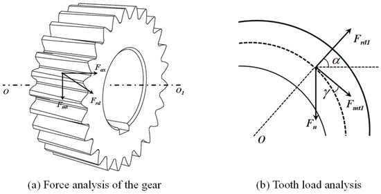
Figure 5.
Force analysis of gears under steady-state conditions.
By solving Equations (17)–(19) simultaneously, the expression for Fn can be obtained as follows:
Finally, the heat of the driving and driven gears is computed using the distribution coefficient (Equation (21)) and applied at meshing points via a User-Defined Function (UDF).
The initial heat flux on the driving gear is shown in Figure 6 below.

Figure 6.
Schematic diagram of heat flux on the driving gear.
2.5. Numerical Model and Boundary Conditions
To accurately capture the dynamic behavior and temperature variations during the gear meshing process, a transient time term is incorporated into the simulation [37]. This study utilizes the finite volume method via the commercial software package Ansys Fluent 2019R3 to model the dynamics of a variable tooth thickness gear system. The internal flow within the gearbox is resolved using the VOF two-phase model, coupled with the RNG k-epsilon turbulence model and the energy equation. The working fluid is treated as a mixture of gas and liquid phases: air (primary phase) with a density of 1.225 kg/m3 and dynamic viscosity of 1.7894 × 10⁻⁵ kg/ (m s), and lubricating oil (secondary phase) with a density of 850 kg/m3 and dynamic viscosity of 0.04 kg/ (m·s), both assumed to have the same temperature. The pressure–velocity coupling is handled using the SIMPLE (Semi-Implicit Method for Pressure-Linked Equations) algorithm [38], while convective and diffusive terms are discretized using a second-order upwind scheme. A first-order implicit scheme is employed for time discretization to improve computational efficiency. The simulation is carried out until the residuals for continuity and momentum equations fall below 10−5, and the result of the energy equation is below 10−6, satisfying the convergence criteria.
Fluid–gear interactions during rotation lead to a continuously changing interface, complicating numerical model calibration. To address this, dynamic mesh technology is introduced to accommodate the interface deformation. It is important to note that, to minimize numerical errors, the mesh size at the interface should be kept as uniform as possible.
To solve the governing equations, the required boundary conditions are defined as follows [39]: A uniform inlet velocity and constant temperature are applied at the oil injection port, while all variables at the oil outlet are set with Neumann boundary conditions. The far-field boundaries are treated with constant temperature, no-slip, and impermeability conditions, and the gear wall surfaces are also subjected to a no-slip condition. Given the significant temperature differences between the meshing and non-meshing regions of the gear teeth, a UDF is implemented to capture the temperature boundary conditions. The driving and driven gears rotate clockwise and counterclockwise, respectively. Detailed parameters are provided in Table 2.
Table 2.
Boundary conditions.
3. Model Validation
To ensure the reliability and applicability of the present results, it is essential to conduct a mesh independence test and validation prior to introducing extensive case studies. This is achieved by comparing theoretical data with numerical results.
After defining the computational domain, the optimal meshing strategy is further evaluated. Mesh refinement is applied to the gear surfaces, meshing region, and areas near the oil injection nozzle, with a mesh size of 0.5 mm, to better capture the heat distribution of the gear teeth and the oil flow phenomena. The remaining areas use a global mesh configuration. The computational mesh is generated using Hypermesh software, with five mesh sizes considered: 2 mm, 3 mm, 4 mm, 5 mm, and 6 mm. A monitoring point is placed 25 mm above the gear meshing location (see Figure 7). Figure 8 presents the corresponding test data. The results show that when the mesh size increases from 4.5 mm to 5.5 mm, the pressure and velocity magnitudes fluctuate by 31.7% and 22.3%, respectively. In contrast, within the 3.5–4.5 mm range, fluctuations remain below 1.6%. Balancing computational cost and accuracy, the 4.5 mm mesh is identified as the optimal configuration (see Figure 9). Furthermore, based on the minimum mesh size (Gridmin = 2.03 × 10⁻⁴) and the Courant number, a time step of 0.001 s is sufficient to meet the demands of large-scale case simulations.

Figure 7.
Monitoring point location.

Figure 8.
Pressure and velocity data for different grid resolutions.

Figure 9.
Overall mesh layout of the gearbox.
Notably, since f is set at constant values (f = 0.06) in this study, the value of Q depends on the normal contact force Fn. Based on the gear structural parameters in Table 1 and Table 2 as well as using Equations (16) and (20), the theoretical normal contact force is calculated to be 2764.117 N. Meanwhile, a dynamic simulation is conducted using specialized software, and the resulting normal contact force is 2546.623 N. By comparing the simulation result with the theoretical value, the error is found to be 7.87%, which falls within the acceptable range. This verifies the rationality and effectiveness of the proposed heat dissipation model.
4. Results and Discussion
An effective approach for monitoring the internal temperature of an involute variable tooth thickness gearbox is the surface-averaging method. Average temperatures at different locations reveal the effects of injection velocity, pitch cone angle, gear width, and axial displacement on temperature distribution. For the placement of internal monitoring sections within the gearbox, monitoring surfaces are positioned 2 mm from both end faces of the driving gear and at the midpoint. The locations of these monitoring surfaces are shown in Figure 10.

Figure 10.
Monitoring section locations within the gearbox.
4.1. Effect of Oil Injection Velocity on Thermal Behavior
The magnitude of the oil injection velocity significantly influences the flow field within the gearbox. Therefore, investigating the impact of injection velocity on the internal temperature distribution is of great importance for optimizing and enhancing gear lubrication performance. Figure 11 presents the average temperatures at the monitoring surfaces inside the gearbox for pitch cone angles of 0°, 2°, and 4°, respectively.

Figure 11.
Average temperatures at internal monitoring sections of the gearbox under different pitch cone angles.
Based on the analysis in the figure above, it can be observed that when the pitch cone angle is 0°, the temperature variation in the gear at different monitoring sections is relatively small. Overall, as the lubrication oil injection velocity increases, the cooling temperature decreases. Under a 2° pitch cone angle, the average temperature inside the gearbox is the highest compared to the 0° and 4° cases, with a temperature of 322.9 Kelvin. Additionally, the temperature at the thinner side of the gear is significantly lower than at the other two monitoring sections. Under a 4° pitch cone angle, the average temperature at each monitoring section is lower compared to the 0° and 2° cases. This is due to previous studies indicating that the 4° pitch cone angle allows for a higher volume fraction of lubrication oil on the gear surface, which in turn facilitates the removal of more heat. Consequently, the temperature for the 4° pitch cone angle is lower than that of the other two designs. Furthermore, the 4° pitch cone angle maintains the performance characteristics of the 2° pitch cone angle, where the temperature is lower at the thinner edge of the gear. The analysis of the average temperatures at the monitoring sections inside the gearbox for different pitch cone angles shows that the 4° pitch cone angle is more favorable for gear cooling. Figure 12 illustrates the relationship between the oil volume fraction and the gear speed under different pitch cone angle conditions.

Figure 12.
The curve depicting the variation in oil volume fraction with gear speed under different cone angle conditions.
4.2. The Effect of Gear Width on Temperature
After prolonged operation, alternating loads and increased tooth wear reduce contact area and enlarge backlash, causing vibration and noise. Involute gears with variable tooth thicknesses (unequal face widths) can alleviate these issues by axial adjustment without changing the center distance. This adjustment decreases backlash and prolongs gear life. For analysis, the gear width ratio is defined as the face width of the driving gear to that of the driven gear (, where and are their respective widths). Temperature variations at different width ratios are compared to examine the effect of gear width on flow field temperature during axial adjustment of variable-tooth-thickness gears.
As shown in Figure 13, with a fixed driven gear width of 26 mm and pitch cone angles of 0°, 2°, and 4°, temperature variations across monitoring sections show consistent trends under different gear width ratios. Specifically, as the width of the driving gear increases with the gear width ratio, the average temperature at all three monitoring sections shows an upward trend. This is primarily due to the altered flow direction caused by the increased driving gear width, which leads to a deflection of the oil jet. Consequently, the lubricant fails to fully reach the effective lubrication area, resulting in a slight temperature rise. Therefore, in designing involute gears with variable tooth thicknesses, smaller gear widths and lower width ratios are recommended. This is feasible as long as strength and axial displacement requirements are satisfied, and the ratio ensures a comparable service life for both gears. This approach facilitates better heat dissipation within the gearbox and enhances lubrication performance.

Figure 13.
Average temperature in the monitoring section inside the gearbox under different gear width ratios.
4.3. The Effect of Axial Displacement on Temperature
In involute gears with variable tooth thickness (i.e., unequal face widths), axial adjustment can reduce backlash and extend service life without changing the center distance. To assess how axial displacement affects gearbox temperature, three gear pairs with different pitch cone angles are tested under identical conditions, and temperature changes at various displacements are observed.
As shown in Figure 14, with constant gear parameters and pitch cone angles of 0°, 2°, and 4°, temperature variations across monitoring sections show a consistent pattern after axial displacement. Regardless of the offset direction, temperature at all monitoring points rises with axial displacement magnitude. The lowest temperature occurs near zero displacement. This trend is primarily due to changes in the flow direction of the lubricant caused by axial offset, regardless of the direction. Under the influence of air entrainment effects, the oil jet deviates from the meshing zone, leading to a slight temperature rise. Therefore, when gear tooth wear occurs, only minimal axial adjustment should be made—ensuring proper backlash—to avoid temperature increase and potential lubrication failure.

Figure 14.
Average temperature at the monitoring section inside the gearbox under different axial displacements.
5. Conclusions
This study investigates the cooling performance of variable-tooth-thickness involute gears under varying oil injection velocities and pitch cone angles. The internal temperature distribution of the gearbox is accurately simulated using the VOF method and UDF-defined heat flux in the mesh region. This provides reliable support for the cooling design of variable-tooth-thickness involute gears. The main conclusions are as follows:
- (1)
- The simulation results indicate that as the oil injection velocity increases, the cooling performance inside the gearbox decreases, though temperature reduction still occurs. A comparison of the temperature data comparison shows that a 15 m/s injection velocity with a 4° pitch cone angle provides a more economical cooling performance than other configurations. These findings support the selection of cost-effective, eco-friendly lubrication speeds and inform similar practical applications.
- (2)
- A larger pitch cone angle markedly reduces the maximum and minimum internal temperatures of the gearbox. This analysis provides a reference for the pitch cone angle design of variable-tooth-thickness involute gears. However, it should also be noted that an excessively large pitch cone angle may result in thinner teeth, thereby reducing their bending fatigue strength. Thus, excessively large pitch cone angles should be avoided, and optimal design requires a balanced consideration of multiple factors.
- (3)
- The influence of gear width on temperature shows that increasing the gear width significantly raises the internal temperature of the gearbox. When the driven wheel tooth width is fixed, selecting a smaller gear width ratio can significantly reduce the internal temperature. This analysis provides a scientific basis for selecting the optimal width for variable-tooth-thickness involute gears.
- (4)
- The temperature response to axial displacement shows that the gearbox temperature increases with larger positive or negative offsets of variable-tooth-thickness involute gears. The minimum temperature occurs at zero displacement. This analysis provides a theoretical reference for selecting appropriate axial backlash adjustments in variable-tooth-thickness involute gear design.
Author Contributions
Conceptualization, H.Z. and Y.L.; methodology, J.G.; software, H.Z.; validation, H.Z. and J.G.; formal analysis, J.G.; investigation, H.Z.; resources, H.Z.; data curation, H.Z.; writing—original draft preparation, H.Z.; writing—review and editing, Y.L. and J.G.; visualization, H.Z.; supervision, Y.L.; project administration, Y.L.; funding acquisition, Y.L. All authors have read and agreed to the published version of the manuscript.
Funding
This work was supported by the National Natural Science Foundation of China under Grant [52265008] and the Innovation Fund Project of Gansu Province Higher Education under Grant [2025B-406].
Data Availability Statement
The original contributions presented in this study are included in the article. Further inquiries can be directed to the corresponding author.
Conflicts of Interest
The authors declare no conflict of interest.
References
- Corsaro, L.; Curà, F.; Sesana, R. Active Thermography for Residual Stresses Identification in Gears by Using Different Heating Sources. Forsch. Ing.-Wes. 2025, 89, 75. [Google Scholar] [CrossRef]
- Lu, R.; Tang, W.; Xue, J.; Huang, Q.; Liu, X. A Lubrication–Heat Transfer Coupling Method for Analyzing Frictional Heat Flux of Spur Gears in Mixed Lubrication. Phys. Fluids 2025, 37, 073101. [Google Scholar] [CrossRef]
- Lu, R.; Tang, W.; Xue, J.; Huang, Q.; Liu, X. A Unified Computational Framework for Meshing Stiffness of Spur Gears Incorporating Lubrication and Thermal Effects. Phys. Fluids 2025, 37, 063106. [Google Scholar] [CrossRef]
- Yu, B.; Yao, C.; Chen, J.; Chen, G.; Liu, K.; Zhao, H.; Zhang, T.; Wang, F. Simulation and Experimental Study on Thermal Characteristics of Linear Conjugate Internal Gear Pumps. Appl. Sci. 2025, 15, 5728. [Google Scholar] [CrossRef]
- Li, X.P.; Xu, J.C.; Yang, Z.M.; Chen, R.; Yang, H. The Influence of Tooth Surface Wear on Dynamic Characteristics of Gear-Bearing System Based on Fractal Theory. J. Comput. Nonlinear Dyn. 2020, 15, 041003. [Google Scholar] [CrossRef]
- Simon, V. Influence of Machine Tool Setting Parameters on EHD Lubrication in Hypoid Gears. Mech. Mach. Theory 2009, 44, 923–937. [Google Scholar] [CrossRef]
- Simon, V.V. Minimization of the Influence of Misalignments on EHD Lubrication in Face-Hobbed Spiral Bevel Gears. In Proceedings of the International Design Engineering Technical Conferences and Computers and Information in Engineering Conference, Portland, OR, USA, 4–7 August 2013; Volume 55928, p. V005T11A037. [Google Scholar]
- Su, J.; Li, S.; Hu, B.; Yin, L.; Zhou, C.; Wang, H.; Hou, S. Innovative Insights into Nanofluid-Enhanced Gear Lubrication: Computational and Experimental Analysis of Churn Mechanisms. Tribol. Int. 2024, 199, 109949. [Google Scholar] [CrossRef]
- Ariura, Y.; Ueno, T.; Suna, T.G.A. The Lubricant Churning Loss in Spur Gear Systems. Bull. JSME 1973, 16, 881–890. [Google Scholar] [CrossRef]
- Diab, Y.; Ville, F.; Houjoh, H.; Sainsot, P.; Velex, P. Experimental and Numerical Investigations on the Air-Pumping Phenomenon in High-Speed Spur and Helical Gears. Proc. Inst. Mech. Eng. Part C J. Mech. Eng. Sci. 2005, 219, 785–800. [Google Scholar] [CrossRef]
- Bones, R.J. Churning Losses of Disc and Gears Running Partially Submerged in Oil. ASME J. Tribol. 1989, 111, 335–359. [Google Scholar]
- Luke, P.; Olver, A.V. A Study of Churning Losses in Dip-Lubricated Spur Gears. Proc. Inst. Mech. Eng. Part G J. Aerosp. Eng. 1999, 213, 337–346. [Google Scholar] [CrossRef]
- Changenet, C.; Velex, P. Housing Influence on Churning Losses in Geared Transmissions. J. Mech. Des. 2007, 130, 068101. [Google Scholar]
- Michaelis, K.; Höhn, B.; Hinterstoißer, M. Influence Factors on Gearbox Power Loss. Ind. Lubr. Tribol. 2011, 63, 46–55. [Google Scholar] [CrossRef]
- Andersson, M.; Sosa, M.; Olofsson, U. Efficiency and Temperature of Spur Gears Using Spray Lubrication Compared to Dip Lubrication. Proc. Inst. Mech. Eng. Part J J. Eng. Tribol. 2017, 231, 1390–1396. [Google Scholar] [CrossRef]
- Ambrose, S.; Morvan, H.; Simmons, K. Investigation of Oil Jet Impingement on a Rotating Gear Using Lattice Boltzmann Method (LBM). In Proceedings of the Turbo Expo: Power for Land, Sea, and Air, ASME, Lillestrøm, Norway, 11–15 June 2018; Volume 50985, p. V001T01A028. [Google Scholar]
- Keller, M.C.; Kromer, C.; Cordes, L.; Schwitzke, C.; Bauer, H.-J. CFD Study of Oil-Jet Gear Interaction Flow Phenomena in Spur Gears. Aeronaut. J. 2020, 124, 1301–1317. [Google Scholar] [CrossRef]
- Akin, L.S.; Mross, J.J.; Townsend, D.P. Study of Lubricant Jet Flow Phenomena in Spur Gears. J. Lubr. Technol. 1975, 97, 283–288. [Google Scholar] [CrossRef]
- Akin, L.S.; Townsend, D.P. Study of Lubricant Jet Flow Phenomena in Spur Gears—Out of Mesh Condition. J. Mech. Des. 1978, 100, 61–68. [Google Scholar][Green Version]
- Akin, L.S.; Townsend, D.P. Into Mesh Lubrication of Spur Gears with Arbitrary Offset Oil Jet. Part 1: For Jet Velocity Less than or Equal to Gear Velocity. J. Mech. Transm. Autom. Des. 1983, 105, 713–718. [Google Scholar] [CrossRef]
- Akin, L.S.; Townsend, D.P. Into Mesh Lubrication of Spur Gears with Arbitrary Offset Oil Jet. Part 2: For Jet Velocities Equal to or Greater than Gear Velocity. J. Mech. Transm. Autom. Des. 1983, 105, 719–724. [Google Scholar] [CrossRef]
- Li, K.; Chen, G.; Liu, D. Study of the Influence of Lubrication Parameters on Gear Lubrication Properties and Efficiency. Ind. Lubr. Tribol. 2016, 68, 647–657. [Google Scholar] [CrossRef]
- Dai, Y.; Wu, W.; Zhou, H.B.; Zhang, J.; Ma, F.Y. Numerical Simulation and Optimization of Oil Jet Lubrication for Rotorcraft Meshing Gears. Int. J. Simul. Model. 2018, 17, 318–326. [Google Scholar] [CrossRef]
- Dai, Y.; Ouyang, B.; Jia, J.; Bian, J. Determination of an Optimal Oil Jet Nozzle Layout for Helical Gear Lubrication: Mathematical Modeling, Numerical Simulation, and Experimental Validation. Complexity 2020, 2020, 2187027. [Google Scholar] [CrossRef]
- Dai, Y.; Ma, F.; Zhu, X.; Su, Q.; Hu, X. Evaluation and Optimization of the Oil Jet Lubrication Performance for Orthogonal Face Gear Drive: Modelling, Simulation and Experimental Validation. Energies 2019, 12, 1935. [Google Scholar] [CrossRef]
- Zhu, X.; Dai, Y.; Ma, F.; Ouyang, B. Mathematical Modeling and Numerical Simulation for Determining an Optimized Oil Jet Layout for Spiral Bevel Gear Lubrication. Proc. Inst. Mech. Eng. Part J J. Eng. Tribol. 2020, 235, 611–628. [Google Scholar] [CrossRef]
- Hu, X.; Li, P.; Quan, C.; Wang, J. CFD Investigation on Oil Injection Lubrication of Meshing Spur Gears via Lattice Boltzmann Method. Lubricants 2022, 10, 184. [Google Scholar] [CrossRef]
- Liu, H.; Jurkschat, T.; Lohner, T.; Stahl, K. Determination of Oil Distribution and Churning Power Loss of Gearboxes by Finite Volume CFD Method. Tribol. Int. 2017, 109, 346–354. [Google Scholar] [CrossRef]
- Bhupinders, V.; Ved, P.C.; Kumar, A.; Chopra, C. CFD Simulation of Transmission for Lubrication Oil Flow, Validation and Churning Loss Reduction. SAE Int. J. Commer. Veh. 2020, 12, 9. [Google Scholar] [CrossRef]
- Wang, Y.; Niu, W.; Chen, Y.; Song, G.; Tang, W. Convection Heat Transfer and Temperature Analysis of Oil Jet Lubricated Spur Gears. Ind. Lubr. Tribol. 2016, 68, 624–631. [Google Scholar] [CrossRef]
- Luo, B.; Li, W. Influence Factors on Bulk Temperature Field of Gear. Proc. Inst. Mech. Eng. Part J J. Eng. Tribol. 2017, 231, 953–964. [Google Scholar] [CrossRef]
- Fatourehchi, E.; Shahmohamadi, H.; Mohammadpour, M.; Rahmani, R.; Theodossiades, S.; Rahnejat, H. Thermal Analysis of an Oil Jet-Dry Sump Transmission Gear under Mixed-Elastohydrodynamic Conditions. J. Tribol. 2018, 140, 051703. [Google Scholar] [CrossRef]
- Deshpande, S.; Joshi, H.; Madhavan, J.; Mason, P. Two-Way Coupled CFD Approach for Predicting Gear Temperature of Oil Jet Lubricated Transmissions. SAE Int. J. Commer. Veh. 2018, 11, 163–170. [Google Scholar] [CrossRef]
- Qiao, S.; Zhou, J.; Zhang, X.; Jiang, H.; Shao, Y.; Shen, Y.; Wang, C. Dynamic Thermal Behavior of Two-Stage Gear Transmission System. J. Vib. Eng. Technol. 2021, 9, 1809–1831. [Google Scholar] [CrossRef]
- Zhou, C.; Su, J.; Jiang, X.; Shi, Z. Numerical Simulation and Experimental Verification for the Sorting Behaviors of Mixed Biomass Particles in a Novel Z-Shaped Fluidized Bed. Chem. Eng. J. 2022, 441, 136109. [Google Scholar] [CrossRef]
- Li, W.; Zhai, P.; Tian, J.; Luo, B. Thermal Analysis of Helical Gear Transmission System Considering Machining and Installation Error. Int. J. Mech. Sci. 2018, 149, 1–17. [Google Scholar] [CrossRef]
- Zhang, S.; Li, B.; Li, A.; Yu, B.; Chen, Z.; Jiang, P. Research on Constant-Flow Water-Saving Device Based on Dynamic Mesh Transient Flow Field Analysis. Water 2024, 16, 2427. [Google Scholar] [CrossRef]
- Reddy, J.N.; Anand, N.; Roy, P. Finite Element and Finite Volume Methods for Heat Transfer and Fluid Dynamics; Cambridge University Press: Cambridge, UK, 2022. [Google Scholar]
- Hildebrand, L.; Genuin, S.; Lohner, T.; Stahl, K. Numerical Analysis of the Heat Transfer of Gears under Oil Dip Lubrication. Tribol. Int. 2024, 195, 109652. [Google Scholar] [CrossRef]


Disclaimer/Publisher’s Note: The statements, opinions and data contained in all publications are solely those of the individual author(s) and contributor(s) and not of MDPI and/or the editor(s). MDPI and/or the editor(s) disclaim responsibility for any injury to people or property resulting from any ideas, methods, instructions or products referred to in the content. |
© 2025 by the authors. Licensee MDPI, Basel, Switzerland. This article is an open access article distributed under the terms and conditions of the Creative Commons Attribution (CC BY) license (https://creativecommons.org/licenses/by/4.0/).